EP3882154B1 - Ecs utilisant l'air d'échappement d'une cabine comme source d'électricité - Google Patents
Ecs utilisant l'air d'échappement d'une cabine comme source d'électricité Download PDFInfo
- Publication number
- EP3882154B1 EP3882154B1 EP21163229.4A EP21163229A EP3882154B1 EP 3882154 B1 EP3882154 B1 EP 3882154B1 EP 21163229 A EP21163229 A EP 21163229A EP 3882154 B1 EP3882154 B1 EP 3882154B1
- Authority
- EP
- European Patent Office
- Prior art keywords
- medium
- control system
- environmental control
- expansion device
- turbine
- Prior art date
- Legal status (The legal status is an assumption and is not a legal conclusion. Google has not performed a legal analysis and makes no representation as to the accuracy of the status listed.)
- Active
Links
Images
Classifications
-
- F—MECHANICAL ENGINEERING; LIGHTING; HEATING; WEAPONS; BLASTING
- F24—HEATING; RANGES; VENTILATING
- F24F—AIR-CONDITIONING; AIR-HUMIDIFICATION; VENTILATION; USE OF AIR CURRENTS FOR SCREENING
- F24F7/00—Ventilation
- F24F7/003—Ventilation in combination with air cleaning
-
- B—PERFORMING OPERATIONS; TRANSPORTING
- B64—AIRCRAFT; AVIATION; COSMONAUTICS
- B64D—EQUIPMENT FOR FITTING IN OR TO AIRCRAFT; FLIGHT SUITS; PARACHUTES; ARRANGEMENT OR MOUNTING OF POWER PLANTS OR PROPULSION TRANSMISSIONS IN AIRCRAFT
- B64D13/00—Arrangements or adaptations of air-treatment apparatus for aircraft crew or passengers, or freight space
- B64D13/06—Arrangements or adaptations of air-treatment apparatus for aircraft crew or passengers, or freight space the air being conditioned
-
- F—MECHANICAL ENGINEERING; LIGHTING; HEATING; WEAPONS; BLASTING
- F03—MACHINES OR ENGINES FOR LIQUIDS; WIND, SPRING, OR WEIGHT MOTORS; PRODUCING MECHANICAL POWER OR A REACTIVE PROPULSIVE THRUST, NOT OTHERWISE PROVIDED FOR
- F03D—WIND MOTORS
- F03D1/00—Wind motors with rotation axis substantially parallel to the air flow entering the rotor
- F03D1/02—Wind motors with rotation axis substantially parallel to the air flow entering the rotor having a plurality of rotors
-
- B—PERFORMING OPERATIONS; TRANSPORTING
- B64—AIRCRAFT; AVIATION; COSMONAUTICS
- B64D—EQUIPMENT FOR FITTING IN OR TO AIRCRAFT; FLIGHT SUITS; PARACHUTES; ARRANGEMENT OR MOUNTING OF POWER PLANTS OR PROPULSION TRANSMISSIONS IN AIRCRAFT
- B64D13/00—Arrangements or adaptations of air-treatment apparatus for aircraft crew or passengers, or freight space
- B64D13/06—Arrangements or adaptations of air-treatment apparatus for aircraft crew or passengers, or freight space the air being conditioned
- B64D2013/0603—Environmental Control Systems
- B64D2013/0618—Environmental Control Systems with arrangements for reducing or managing bleed air, using another air source, e.g. ram air
-
- B—PERFORMING OPERATIONS; TRANSPORTING
- B64—AIRCRAFT; AVIATION; COSMONAUTICS
- B64D—EQUIPMENT FOR FITTING IN OR TO AIRCRAFT; FLIGHT SUITS; PARACHUTES; ARRANGEMENT OR MOUNTING OF POWER PLANTS OR PROPULSION TRANSMISSIONS IN AIRCRAFT
- B64D13/00—Arrangements or adaptations of air-treatment apparatus for aircraft crew or passengers, or freight space
- B64D13/06—Arrangements or adaptations of air-treatment apparatus for aircraft crew or passengers, or freight space the air being conditioned
- B64D2013/0603—Environmental Control Systems
- B64D2013/0644—Environmental Control Systems including electric motors or generators
-
- B—PERFORMING OPERATIONS; TRANSPORTING
- B64—AIRCRAFT; AVIATION; COSMONAUTICS
- B64D—EQUIPMENT FOR FITTING IN OR TO AIRCRAFT; FLIGHT SUITS; PARACHUTES; ARRANGEMENT OR MOUNTING OF POWER PLANTS OR PROPULSION TRANSMISSIONS IN AIRCRAFT
- B64D13/00—Arrangements or adaptations of air-treatment apparatus for aircraft crew or passengers, or freight space
- B64D13/06—Arrangements or adaptations of air-treatment apparatus for aircraft crew or passengers, or freight space the air being conditioned
- B64D2013/0603—Environmental Control Systems
- B64D2013/0648—Environmental Control Systems with energy recovery means, e.g. using turbines
-
- Y—GENERAL TAGGING OF NEW TECHNOLOGICAL DEVELOPMENTS; GENERAL TAGGING OF CROSS-SECTIONAL TECHNOLOGIES SPANNING OVER SEVERAL SECTIONS OF THE IPC; TECHNICAL SUBJECTS COVERED BY FORMER USPC CROSS-REFERENCE ART COLLECTIONS [XRACs] AND DIGESTS
- Y02—TECHNOLOGIES OR APPLICATIONS FOR MITIGATION OR ADAPTATION AGAINST CLIMATE CHANGE
- Y02E—REDUCTION OF GREENHOUSE GAS [GHG] EMISSIONS, RELATED TO ENERGY GENERATION, TRANSMISSION OR DISTRIBUTION
- Y02E10/00—Energy generation through renewable energy sources
- Y02E10/70—Wind energy
- Y02E10/72—Wind turbines with rotation axis in wind direction
-
- Y—GENERAL TAGGING OF NEW TECHNOLOGICAL DEVELOPMENTS; GENERAL TAGGING OF CROSS-SECTIONAL TECHNOLOGIES SPANNING OVER SEVERAL SECTIONS OF THE IPC; TECHNICAL SUBJECTS COVERED BY FORMER USPC CROSS-REFERENCE ART COLLECTIONS [XRACs] AND DIGESTS
- Y02—TECHNOLOGIES OR APPLICATIONS FOR MITIGATION OR ADAPTATION AGAINST CLIMATE CHANGE
- Y02T—CLIMATE CHANGE MITIGATION TECHNOLOGIES RELATED TO TRANSPORTATION
- Y02T50/00—Aeronautics or air transport
- Y02T50/50—On board measures aiming to increase energy efficiency
Definitions
- Embodiments of the disclosure relate to environmental control systems, and more specifically to an environmental control system of an aircraft.
- Aircraft need to have their internal environment controlled.
- contemporary air conditioning systems are supplied a pressure at cruise that is approximately 30 psig to 35 psig (206.8 to 241.3 kPa).
- the trend in the aerospace industry today is towards smaller systems with higher efficiency.
- One approach to improve efficiency of an aircraft environmental control system is to eliminate the bleed air entirely and use electrical power to compress outside air.
- a second approach is to use lower engine pressure.
- the third approach is to use the energy in the cabin outflow air to compress outside air and bring it into the cabin.
- An ECS is disclosed in US 9669936 , in US 2018/370636 A1 and also in EP0629548A1 .
- an environmental control system of a vehicle is provided as defined by claim 1.
- the expansion device includes a turbo-generator.
- the second medium output from the expansion device is exhausted overboard.
- a ram air circuit including a ram air shell having a ram air heat exchanger positioned therein.
- the second medium output from the expansion device is provided to the ram air shell.
- the environmental control system includes an outlet, and the first medium provided to the outlet has at least one of a temperature and pressure different from the first medium provided to the first inlet.
- the first medium is bleed air.
- the second medium is cabin outflow air.
- the energy extracted from the second medium within the expansion device is provided to a battery.
- the one or more loads that receive the energy extracted from the second medium within the expansion device are external to the environmental control system.
- a method of operating an environmental control system of a vehicle is provided as defined by claim 10.
- the first medium is bleed air and the second medium is cabin outflow air.
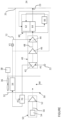
- FIG. 1 is a simplified schematic diagram of a system according to an embodiment.
- Embodiments herein provide an environmental control system of an aircraft that mixes mediums from different sources and uses energy from one or more of the different sources to power the environmental control system and to provide cabin pressurization and cooling at a high fuel burn efficiency.
- the mediums described herein are generally types of air; however, it should be understood that other mediums, such as gases, liquids, fluidized solids, or slurries are also contemplated herein.
- the system 20 can receive a first medium A1 at an inlet 22 and provide a conditioned form of the first medium to one or more loads, such as a volume 24 for example, via an outlet 23.
- the first medium A1 is bleed air, which can be pressurized air originating from (e.g., being "bled" from) an engine or auxiliary power unit of the aircraft. It shall be understood that one or more of the temperature, humidity, flow rate, and pressure of the bleed air can vary based upon the compressor stage from which the air is drawn and revolutions per minute of the engine, or the auxiliary power unit from which the air is drawn.
- the system 20 is also configured to receive a second medium A2 via a second inlet 25, such as from the volume 24.
- the volume 24 is the cabin of an aircraft and the second medium A2 is cabin discharge or outflow air, which is air leaving the volume 24 that would typically be discharged overboard.
- the system 20 is configured to extract work from the second medium A2. In this manner, the pressurized air A2 of the volume 24 can be utilized by the system 20 to achieve certain operations.
- the environmental control system 20 includes a ram air circuit 30 including a shell or duct, illustrated schematically at 32, within which one or more heat exchangers are located.
- the shell 32 can receive and direct a medium, such as ram air AR for example, through a portion of the system 20.
- the one or more heat exchangers 34 arranged within the shell 32 may be referred to as ram heat exchangers and are built for efficient heat transfer from one medium to another.
- ram air AR such as outside air for example, acts as a heat sink to cool a medium passing there through, for example the first medium A1.
- a fan 36 is disposed within the ram air shell 32.
- the fan 36 is operable to force via push or pull methods a medium (e.g., ram air) through the shell 32 across the one or more ram heat exchangers 34.
- a medium e.g., ram air
- the system 20 additionally comprises at least one compression device.
- the compression device 40 is a mechanical device that includes components for performing thermodynamic work on a medium (e.g., extracts work from or applies work to the first medium A1, the second medium A2, by raising and/or lowering pressure and by raising and/or lowering temperature).
- Examples of the compression device 40 include an air cycle machine, a three-wheel air cycle machine, a four-wheel air cycle machine, etc.
- the compression device 40 includes a compressor 42, a turbine 44, and a power turbine 46 operably coupled to each other via a shaft 48.
- the compressor 42 is a mechanical device that raises a pressure of a medium and can be driven by another mechanical device (e.g., a motor or a medium via a turbine). Examples of compressor types include centrifugal, diagonal or mixed-flow, axial-flow, reciprocating, ionic liquid piston, rotary screw, rotary vane, scroll, diaphragm, air bubble, etc.
- the compressor 42 is configured to receive and pressurize the first medium A1.
- the turbine 44 and the power turbine 46 are mechanical devices that expand a medium and extract work therefrom (also referred to as extracting energy). In the compression device 40, the turbines 44, 46 are configured to drive the compressor 42 via the shaft 48.
- the expansion device 50 is a turbo-generator including a turbine 52 and an electrical generator 54 operably coupled via a shaft 56.
- the turbine 52 is a mechanical device that expands a medium and extracts work therefrom.
- the turbine 52 drives an impeller (not shown) of the generator 54 via the shaft 56.
- the turbine 52 can comprise a nozzle configured to accelerate a medium supplied thereto for entry into a turbine impeller (not shown).
- the system 20 additionally includes at least one dehumidification system 60.
- the dehumidification system 60 includes a reheater 62, a condenser 64, and a water extractor 66.
- the reheater 62 and the condenser 64 are particular types of heat exchangers.
- the water extractor 66 is a mechanical device that performs a process of removing water from the medium. Together, the condenser 64, the water extractor 66, and/or the reheater 62 can be combined to form a medium pressure water separator.
- Valves e.g., flow regulation device or mass flow valve
- Valves are devices that regulate, direct, and/or control a flow of a medium by opening, closing, or partially obstructing various passageways within the tubes, pipes, etc. of the system. Valves can be operated by actuators, such that flow rates of the medium in any portion of the system 20 can be regulated to a desired value.
- the system 20 is operable in a plurality of modes, selectable based on a flight condition of the aircraft.
- the system 20 is operable in a first mode when the aircraft is on the ground and in a second mode when the aircraft is in flight, such as high altitude cruise, climb, and/or descent for example.
- the heated second medium A2 is expanded across the turbine 52 of the expansion device and work is extracted therefrom.
- the work extracted by the turbine 52 of the expansion device 50 drives the generator 54, thereby creating electricity.
- the electricity created within the generator may be distributed to one or more electrical loads of the aircraft, such as remote from the environmental control system 20, or alternatively, may be stored within a battery (not shown).
- the cooled, reduced pressure second medium A2 output from the turbine 52 of the expansion device 50 may be exhausted overboard, or alternatively, may be dumped into the ram air circuit 30, upstream or downstream of the at least one heat exchanger 34. In embodiments where the second medium A2 is provided to the ram air circuit 30, this additional air may be used to supplement the cooling performed by the ram air circuit 30.
- the first medium A1 output from the outflow heat exchanger 70 is provided to at least one ram heat exchanger 34.
- the fan 36 is used to move air, such as ram air for example, through or across the ram air heat exchanger 34 to further cool the temperature of the first medium A1 within the ran air heat exchanger 34.
- the fan 36 is a tip turbine fan driven by a motor 38.
- the fan 36 may be part of the compression device or alternatively, the expansion device 50.
- the cooled, reduced pressure first medium A1 output from the power turbine 46 is typically provided to the dehumidification system 60.
- the first medium A1 is configured to flow through the reheater 62, the condenser 64, and the water extractor 66 sequentially.
- the first medium A1 is cooled and further cooled within the reheater 62 and the condenser 64, respectively, causing any moisture within the first medium A1 to condense. This moisture is then removed within the water extractor 66 and the first medium A1 is provided again to the reheater 62.
- the first medium A1 is at least partially heated to produce a warm, dry first medium A1.
- the warm, dry first medium A1 may be provided to an inlet of the turbine 44.
- the warm, dry first medium A1 is expanded across the turbine 44 and work is extracted therefrom.
- the work extracted by the turbine 44 is combined with the work extracted from the power turbine 46 to drive the compressor 42 via the shaft 48.
- the cooled, reduced pressure first medium A1 output from the turbine 44 is then provided to the condenser 64, where the first medium is heated prior to being delivered to one or more loads of the aircraft, such as the volume 24 for example.
- Operation of the ECS 20 in a second mode of operation is similar to operation in the first mode.
- the flow of the first medium A1 is configured to bypass the power turbine 46.
- the compressor 42 is driven solely by the energy extracted via turbine 44.
- the first medium A1 is pressurized and heated within the compressor 42, is partially cooled within the outflow heat exchanger 70, and is further cooled within the ram air heat exchanger 34.
- the fan 36 may only be used to move ram air through the ram air circuit 30 in instances where the ram recovery, for example the pressure of the ram air provided to the ram air circuit 30, is insufficient to drive the ram air flow across the heat exchanger 34.
- the fan 36 is only driven when the aircraft is on the ground, at low altitude, or in a low speed operation. However, during cruise at high altitude for example, the fan 36 need not be used to facilitate movement of the ram air.
- the first medium A1 is configured to flow through a bypass conduit 72, directly to an inlet of the turbine 44.
- the valve V1 is at least partially open, thereby allowing some or all of the first medium A1 to flow into the bypass conduit 72.
- the cooled, reduced pressure first medium A1 output from the turbine 44 is then provided to the condenser 64, where the first medium A1 before being delivered to one or more loads of the aircraft, such as the volume 24 for example.
- the valve V1 is only partially open, a portion of the first medium A1 will follow the flow path described with respect to the first mode.
- the second medium A2 is heated, such as via a heat exchange relationship with the first medium A1, to increase and/or maximize the energy extracted from the second medium A2, and therefore the electrical energy that can be collected or generated using the second medium A2.
Landscapes
- Engineering & Computer Science (AREA)
- General Health & Medical Sciences (AREA)
- Chemical & Material Sciences (AREA)
- Combustion & Propulsion (AREA)
- Mechanical Engineering (AREA)
- General Engineering & Computer Science (AREA)
- Health & Medical Sciences (AREA)
- Pulmonology (AREA)
- Aviation & Aerospace Engineering (AREA)
- Sustainable Development (AREA)
- Sustainable Energy (AREA)
- Life Sciences & Earth Sciences (AREA)
- Engine Equipment That Uses Special Cycles (AREA)
- Structures Of Non-Positive Displacement Pumps (AREA)
Claims (12)
- Système de climatisation d'un véhicule comprenant :une première entrée (22) pour fournir un premier milieu ;une deuxième entrée pour fournir un deuxième milieu ;un dispositif de compression (40) agencé en communication fluidique avec la première entrée ;un dispositif d'expansion (50) séparé du dispositif de compression, le dispositif d'expansion étant agencé en communication fluidique avec la deuxième entrée, dans lequel l'énergie extraite du deuxième milieu à l'intérieur du dispositif d'expansion est fournie à une ou plusieurs charges du véhicule ; etcomprenant également un échangeur de chaleur (70) agencé en amont du dispositif d'expansion par rapport à un écoulement du deuxième milieu, dans lequel la chaleur est transférée du premier milieu au deuxième milieu dans l'échangeur de chaleur ;caractérisé en ce que :le dispositif de compression comprend un compresseur (42), une turbine (44) et une turbine de travail (46), accouplés de manière fonctionnelle par l'intermédiaire d'un arbre (48) ; etdans lequel à la fois la turbine et la turbine de travail sont configurées pour recevoir un écoulement du premier milieu ; etdans lequel le système de climatisation peut fonctionner dans une pluralité de modes comprenant un premier mode et un deuxième mode, dans lequel, dans le premier mode, l'énergie extraite à la fois de la turbine et de la turbine de travail est utilisée pour faire fonctionner le compresseur, et dans le deuxième mode, l'énergie extraite uniquement de la turbine est utilisée pour faire fonctionner le compresseur.
- Système de climatisation selon la revendication 1, dans lequel le dispositif d'expansion comprend un turbogénérateur.
- Système de climatisation selon une quelconque revendication précédente, dans lequel le deuxième milieu sortant du dispositif d'expansion est évacué vers l'extérieur.
- Système de climatisation selon une quelconque revendication précédente, comprenant également un circuit d'air dynamique (30) comportant une enveloppe d'air dynamique (32) ayant un échangeur de chaleur d'air dynamique (34) positionné en son sein.
- Système de climatisation selon la revendication 4, dans lequel le deuxième milieu sortant du dispositif d'expansion est fourni à l'enveloppe d'air dynamique.
- Système de climatisation selon une quelconque revendication précédente, dans lequel le système de climatisation comprend une sortie (23), et le premier milieu fourni à la sortie présente au moins l'une parmi une température et une pression différentes de celles du premier milieu fourni à la première entrée.
- Système de climatisation selon une quelconque revendication précédente, dans lequel le premier milieu est de l'air de prélèvement ; et/ou dans lequel le deuxième milieu est de l'air d'échappement de cabine.
- Système de climatisation selon une quelconque revendication précédente, dans lequel l'énergie extraite du deuxième milieu à l'intérieur du dispositif d'expansion est fournie à une batterie.
- Système de climatisation selon une quelconque revendication précédente, dans lequel la ou les charges qui reçoivent l'énergie extraite du deuxième milieu à l'intérieur du dispositif d'expansion sont externes au système de climatisation.
- Procédé de fonctionnement d'un système de climatisation selon une quelconque revendication précédente, le procédé comprenant :la fourniture d'un premier milieu à la première entrée (22) ;l'ajustement d'au moins l'une parmi une température et une pression du premier milieu à l'intérieur du système de climatisation pour produire un premier milieu climatisé ;la fourniture d'un deuxième milieu à la deuxième entrée ; etla génération de l'électricité en extrayant de l'énergie du deuxième milieu par l'intermédiaire d'un dispositif d'expansion (50) ; etcomprenant également le chauffage du deuxième milieu à l'intérieur de l'échangeur de chaleur positionné en amont du dispositif d'expansion avant d'en extraire l'énergie.
- Procédé selon la revendication 10, comprenant également la fourniture de l'électricité générée à une ou plusieurs charges du véhicule.
- Procédé selon la revendication 10 ou 11, comprenant également l'évacuation du deuxième milieu du dispositif d'expansion vers l'extérieur ; ou comprenant également l'évacuation du deuxième milieu du dispositif d'expansion à l'intérieur d'un circuit d'air dynamique.
Applications Claiming Priority (1)
| Application Number | Priority Date | Filing Date | Title |
|---|---|---|---|
| US202062990742P | 2020-03-17 | 2020-03-17 |
Publications (2)
| Publication Number | Publication Date |
|---|---|
| EP3882154A1 EP3882154A1 (fr) | 2021-09-22 |
| EP3882154B1 true EP3882154B1 (fr) | 2024-12-25 |
Family
ID=74947219
Family Applications (1)
| Application Number | Title | Priority Date | Filing Date |
|---|---|---|---|
| EP21163229.4A Active EP3882154B1 (fr) | 2020-03-17 | 2021-03-17 | Ecs utilisant l'air d'échappement d'une cabine comme source d'électricité |
Country Status (2)
| Country | Link |
|---|---|
| US (1) | US11629870B2 (fr) |
| EP (1) | EP3882154B1 (fr) |
Citations (1)
| Publication number | Priority date | Publication date | Assignee | Title |
|---|---|---|---|---|
| EP0629548A1 (fr) * | 1993-06-18 | 1994-12-21 | DaimlerChrysler Aerospace Airbus Gesellschaft mit beschränkter Haftung | Dispositif de récupération d'énergie à bord d'un avion, en particulier un avion de passagers |
Family Cites Families (14)
| Publication number | Priority date | Publication date | Assignee | Title |
|---|---|---|---|---|
| US5967461A (en) | 1997-07-02 | 1999-10-19 | Mcdonnell Douglas Corp. | High efficiency environmental control systems and methods |
| US6681592B1 (en) | 2001-02-16 | 2004-01-27 | Hamilton Sundstrand Corporation | Electrically driven aircraft cabin ventilation and environmental control system |
| US6526775B1 (en) | 2001-09-14 | 2003-03-04 | The Boeing Company | Electric air conditioning system for an aircraft |
| US9669936B1 (en) * | 2012-10-24 | 2017-06-06 | The Boeing Company | Aircraft air conditioning systems and methods |
| US10288325B2 (en) * | 2013-03-14 | 2019-05-14 | Rolls-Royce Corporation | Trans-critical vapor cycle system with improved heat rejection |
| WO2015026431A1 (fr) | 2013-08-21 | 2015-02-26 | Hamilton Sundstrand Corporation | Système de générateur et appareil de régulation environnementale |
| US11466904B2 (en) | 2014-11-25 | 2022-10-11 | Hamilton Sundstrand Corporation | Environmental control system utilizing cabin air to drive a power turbine of an air cycle machine and utilizing multiple mix points for recirculation air in accordance with pressure mode |
| US20170268837A1 (en) * | 2016-03-16 | 2017-09-21 | Hamilton Sundstrand Corporation | Pack-and-a-half architecture for environmental control systems |
| US10731501B2 (en) * | 2016-04-22 | 2020-08-04 | Hamilton Sundstrand Corporation | Environmental control system utilizing a motor assist and an enhanced compressor |
| US10773807B2 (en) * | 2016-05-26 | 2020-09-15 | Hamilton Sunstrand Corporation | Energy flow of an advanced environmental control system |
| US10526092B2 (en) * | 2017-04-03 | 2020-01-07 | Hamilton Sundstrand Corporation | Turbine-assisted cabin air compressor |
| FR3068005B1 (fr) | 2017-06-23 | 2019-07-26 | Liebherr-Aerospace Toulouse | Systeme et procede de controle environnemental d'une cabine d'un aeronef et aeronef equipe d'un tel systeme de controle |
| US10611487B2 (en) * | 2018-01-16 | 2020-04-07 | The Boeing Company | Vehicle air conditioning pack with air cycle assembly |
| EP3572329A1 (fr) | 2018-05-24 | 2019-11-27 | Rolls-Royce plc | Système de réglage environnemental d'un aéronef |
-
2021
- 2021-01-21 US US17/154,672 patent/US11629870B2/en active Active
- 2021-03-17 EP EP21163229.4A patent/EP3882154B1/fr active Active
Patent Citations (1)
| Publication number | Priority date | Publication date | Assignee | Title |
|---|---|---|---|---|
| EP0629548A1 (fr) * | 1993-06-18 | 1994-12-21 | DaimlerChrysler Aerospace Airbus Gesellschaft mit beschränkter Haftung | Dispositif de récupération d'énergie à bord d'un avion, en particulier un avion de passagers |
Also Published As
| Publication number | Publication date |
|---|---|
| US11629870B2 (en) | 2023-04-18 |
| US20210362858A1 (en) | 2021-11-25 |
| EP3882154A1 (fr) | 2021-09-22 |
Similar Documents
| Publication | Publication Date | Title |
|---|---|---|
| EP3489142B1 (fr) | Système de commande environnemental d'aéronef avec des turbines à air de prélèvement en série | |
| US11192655B2 (en) | Regenerative system ECOECS | |
| US10953992B2 (en) | Mixing bleed and ram air using an air cycle machine with two turbines | |
| US11851192B2 (en) | Aircraft environmental control system | |
| CN107434047B (zh) | 用于环境控制系统的涡轮机的多喷嘴构造 | |
| EP3750808B1 (fr) | Utilisation de purge d'air pour fournir de l'air extérieur à une cabine | |
| EP3882153B1 (fr) | Ecs d'air frais | |
| EP4005925A1 (fr) | Architecture d'air ambiant avec machine à cycle d'air unique et séparateur d'eau haute pression | |
| EP3712070A1 (fr) | Système de contrôle environnemental restreint pour aéronef | |
| EP4331991A1 (fr) | Système de contrôle environnemental à faible pression d'entrée | |
| EP3882154B1 (fr) | Ecs utilisant l'air d'échappement d'une cabine comme source d'électricité | |
| EP3712071A1 (fr) | Système de contrôle environnemental pour aéronef | |
| US20250074601A1 (en) | Less bleed environmental control system | |
| US12234018B2 (en) | Environmental control system with no bleed driven throttle | |
| US20250026479A1 (en) | Environmental control system with adaptive turbine arrangement | |
| US20250304262A1 (en) | Bleedless environmental control system with motorized air cycle machine | |
| EP4015391A1 (fr) | Compresseur électrique et turbine génératrice d'énergie, recyclant l'air de prélèvement du moteur |
Legal Events
| Date | Code | Title | Description |
|---|---|---|---|
| PUAI | Public reference made under article 153(3) epc to a published international application that has entered the european phase |
Free format text: ORIGINAL CODE: 0009012 |
|
| STAA | Information on the status of an ep patent application or granted ep patent |
Free format text: STATUS: THE APPLICATION HAS BEEN PUBLISHED |
|
| AK | Designated contracting states |
Kind code of ref document: A1 Designated state(s): AL AT BE BG CH CY CZ DE DK EE ES FI FR GB GR HR HU IE IS IT LI LT LU LV MC MK MT NL NO PL PT RO RS SE SI SK SM TR |
|
| STAA | Information on the status of an ep patent application or granted ep patent |
Free format text: STATUS: REQUEST FOR EXAMINATION WAS MADE |
|
| 17P | Request for examination filed |
Effective date: 20220322 |
|
| RBV | Designated contracting states (corrected) |
Designated state(s): AL AT BE BG CH CY CZ DE DK EE ES FI FR GB GR HR HU IE IS IT LI LT LU LV MC MK MT NL NO PL PT RO RS SE SI SK SM TR |
|
| STAA | Information on the status of an ep patent application or granted ep patent |
Free format text: STATUS: EXAMINATION IS IN PROGRESS |
|
| 17Q | First examination report despatched |
Effective date: 20230301 |
|
| GRAP | Despatch of communication of intention to grant a patent |
Free format text: ORIGINAL CODE: EPIDOSNIGR1 |
|
| STAA | Information on the status of an ep patent application or granted ep patent |
Free format text: STATUS: GRANT OF PATENT IS INTENDED |
|
| INTG | Intention to grant announced |
Effective date: 20240725 |
|
| GRAS | Grant fee paid |
Free format text: ORIGINAL CODE: EPIDOSNIGR3 |
|
| GRAA | (expected) grant |
Free format text: ORIGINAL CODE: 0009210 |
|
| STAA | Information on the status of an ep patent application or granted ep patent |
Free format text: STATUS: THE PATENT HAS BEEN GRANTED |
|
| AK | Designated contracting states |
Kind code of ref document: B1 Designated state(s): AL AT BE BG CH CY CZ DE DK EE ES FI FR GB GR HR HU IE IS IT LI LT LU LV MC MK MT NL NO PL PT RO RS SE SI SK SM TR |
|
| REG | Reference to a national code |
Ref country code: GB Ref legal event code: FG4D |
|
| REG | Reference to a national code |
Ref country code: CH Ref legal event code: EP |
|
| REG | Reference to a national code |
Ref country code: DE Ref legal event code: R096 Ref document number: 602021023755 Country of ref document: DE |
|
| REG | Reference to a national code |
Ref country code: IE Ref legal event code: FG4D |
|
| REG | Reference to a national code |
Ref country code: LT Ref legal event code: MG9D |
|
| PG25 | Lapsed in a contracting state [announced via postgrant information from national office to epo] |
Ref country code: HR Free format text: LAPSE BECAUSE OF FAILURE TO SUBMIT A TRANSLATION OF THE DESCRIPTION OR TO PAY THE FEE WITHIN THE PRESCRIBED TIME-LIMIT Effective date: 20241225 |
|
| PG25 | Lapsed in a contracting state [announced via postgrant information from national office to epo] |
Ref country code: FI Free format text: LAPSE BECAUSE OF FAILURE TO SUBMIT A TRANSLATION OF THE DESCRIPTION OR TO PAY THE FEE WITHIN THE PRESCRIBED TIME-LIMIT Effective date: 20241225 |
|
| PG25 | Lapsed in a contracting state [announced via postgrant information from national office to epo] |
Ref country code: BG Free format text: LAPSE BECAUSE OF FAILURE TO SUBMIT A TRANSLATION OF THE DESCRIPTION OR TO PAY THE FEE WITHIN THE PRESCRIBED TIME-LIMIT Effective date: 20241225 |
|
| PG25 | Lapsed in a contracting state [announced via postgrant information from national office to epo] |
Ref country code: NO Free format text: LAPSE BECAUSE OF FAILURE TO SUBMIT A TRANSLATION OF THE DESCRIPTION OR TO PAY THE FEE WITHIN THE PRESCRIBED TIME-LIMIT Effective date: 20250325 |
|
| PG25 | Lapsed in a contracting state [announced via postgrant information from national office to epo] |
Ref country code: GR Free format text: LAPSE BECAUSE OF FAILURE TO SUBMIT A TRANSLATION OF THE DESCRIPTION OR TO PAY THE FEE WITHIN THE PRESCRIBED TIME-LIMIT Effective date: 20250326 Ref country code: LV Free format text: LAPSE BECAUSE OF FAILURE TO SUBMIT A TRANSLATION OF THE DESCRIPTION OR TO PAY THE FEE WITHIN THE PRESCRIBED TIME-LIMIT Effective date: 20241225 |
|
| PGFP | Annual fee paid to national office [announced via postgrant information from national office to epo] |
Ref country code: AT Payment date: 20250417 Year of fee payment: 5 |
|
| PG25 | Lapsed in a contracting state [announced via postgrant information from national office to epo] |
Ref country code: RS Free format text: LAPSE BECAUSE OF FAILURE TO SUBMIT A TRANSLATION OF THE DESCRIPTION OR TO PAY THE FEE WITHIN THE PRESCRIBED TIME-LIMIT Effective date: 20250325 |
|
| REG | Reference to a national code |
Ref country code: NL Ref legal event code: MP Effective date: 20241225 |
|
| PG25 | Lapsed in a contracting state [announced via postgrant information from national office to epo] |
Ref country code: NL Free format text: LAPSE BECAUSE OF FAILURE TO SUBMIT A TRANSLATION OF THE DESCRIPTION OR TO PAY THE FEE WITHIN THE PRESCRIBED TIME-LIMIT Effective date: 20241225 |
|
| REG | Reference to a national code |
Ref country code: AT Ref legal event code: MK05 Ref document number: 1753981 Country of ref document: AT Kind code of ref document: T Effective date: 20241225 |
|
| PG25 | Lapsed in a contracting state [announced via postgrant information from national office to epo] |
Ref country code: SM Free format text: LAPSE BECAUSE OF FAILURE TO SUBMIT A TRANSLATION OF THE DESCRIPTION OR TO PAY THE FEE WITHIN THE PRESCRIBED TIME-LIMIT Effective date: 20241225 |
|
| PG25 | Lapsed in a contracting state [announced via postgrant information from national office to epo] |
Ref country code: PL Free format text: LAPSE BECAUSE OF FAILURE TO SUBMIT A TRANSLATION OF THE DESCRIPTION OR TO PAY THE FEE WITHIN THE PRESCRIBED TIME-LIMIT Effective date: 20241225 |
|
| PG25 | Lapsed in a contracting state [announced via postgrant information from national office to epo] |
Ref country code: ES Free format text: LAPSE BECAUSE OF FAILURE TO SUBMIT A TRANSLATION OF THE DESCRIPTION OR TO PAY THE FEE WITHIN THE PRESCRIBED TIME-LIMIT Effective date: 20241225 |
|
| PG25 | Lapsed in a contracting state [announced via postgrant information from national office to epo] |
Ref country code: IS Free format text: LAPSE BECAUSE OF FAILURE TO SUBMIT A TRANSLATION OF THE DESCRIPTION OR TO PAY THE FEE WITHIN THE PRESCRIBED TIME-LIMIT Effective date: 20250425 |
|
| PG25 | Lapsed in a contracting state [announced via postgrant information from national office to epo] |
Ref country code: PT Free format text: LAPSE BECAUSE OF FAILURE TO SUBMIT A TRANSLATION OF THE DESCRIPTION OR TO PAY THE FEE WITHIN THE PRESCRIBED TIME-LIMIT Effective date: 20250428 |
|
| PG25 | Lapsed in a contracting state [announced via postgrant information from national office to epo] |
Ref country code: EE Free format text: LAPSE BECAUSE OF FAILURE TO SUBMIT A TRANSLATION OF THE DESCRIPTION OR TO PAY THE FEE WITHIN THE PRESCRIBED TIME-LIMIT Effective date: 20241225 |
|
| PG25 | Lapsed in a contracting state [announced via postgrant information from national office to epo] |
Ref country code: RO Free format text: LAPSE BECAUSE OF FAILURE TO SUBMIT A TRANSLATION OF THE DESCRIPTION OR TO PAY THE FEE WITHIN THE PRESCRIBED TIME-LIMIT Effective date: 20241225 Ref country code: AT Free format text: LAPSE BECAUSE OF FAILURE TO SUBMIT A TRANSLATION OF THE DESCRIPTION OR TO PAY THE FEE WITHIN THE PRESCRIBED TIME-LIMIT Effective date: 20241225 |
|
| PG25 | Lapsed in a contracting state [announced via postgrant information from national office to epo] |
Ref country code: SK Free format text: LAPSE BECAUSE OF FAILURE TO SUBMIT A TRANSLATION OF THE DESCRIPTION OR TO PAY THE FEE WITHIN THE PRESCRIBED TIME-LIMIT Effective date: 20241225 |
|
| PG25 | Lapsed in a contracting state [announced via postgrant information from national office to epo] |
Ref country code: CZ Free format text: LAPSE BECAUSE OF FAILURE TO SUBMIT A TRANSLATION OF THE DESCRIPTION OR TO PAY THE FEE WITHIN THE PRESCRIBED TIME-LIMIT Effective date: 20241225 |
|
| PG25 | Lapsed in a contracting state [announced via postgrant information from national office to epo] |
Ref country code: IT Free format text: LAPSE BECAUSE OF FAILURE TO SUBMIT A TRANSLATION OF THE DESCRIPTION OR TO PAY THE FEE WITHIN THE PRESCRIBED TIME-LIMIT Effective date: 20241225 |
|
| PG25 | Lapsed in a contracting state [announced via postgrant information from national office to epo] |
Ref country code: SE Free format text: LAPSE BECAUSE OF FAILURE TO SUBMIT A TRANSLATION OF THE DESCRIPTION OR TO PAY THE FEE WITHIN THE PRESCRIBED TIME-LIMIT Effective date: 20241225 |
|
| REG | Reference to a national code |
Ref country code: DE Ref legal event code: R097 Ref document number: 602021023755 Country of ref document: DE |
|
| PG25 | Lapsed in a contracting state [announced via postgrant information from national office to epo] |
Ref country code: DK Free format text: LAPSE BECAUSE OF FAILURE TO SUBMIT A TRANSLATION OF THE DESCRIPTION OR TO PAY THE FEE WITHIN THE PRESCRIBED TIME-LIMIT Effective date: 20241225 |
|
| PG25 | Lapsed in a contracting state [announced via postgrant information from national office to epo] |
Ref country code: MC Free format text: LAPSE BECAUSE OF FAILURE TO SUBMIT A TRANSLATION OF THE DESCRIPTION OR TO PAY THE FEE WITHIN THE PRESCRIBED TIME-LIMIT Effective date: 20241225 |
|
| REG | Reference to a national code |
Ref country code: CH Ref legal event code: H13 Free format text: ST27 STATUS EVENT CODE: U-0-0-H10-H13 (AS PROVIDED BY THE NATIONAL OFFICE) Effective date: 20251024 |
|
| PLBE | No opposition filed within time limit |
Free format text: ORIGINAL CODE: 0009261 |
|
| STAA | Information on the status of an ep patent application or granted ep patent |
Free format text: STATUS: NO OPPOSITION FILED WITHIN TIME LIMIT |
|
| PG25 | Lapsed in a contracting state [announced via postgrant information from national office to epo] |
Ref country code: LU Free format text: LAPSE BECAUSE OF NON-PAYMENT OF DUE FEES Effective date: 20250317 |
|
| 26N | No opposition filed |
Effective date: 20250926 |
|
| REG | Reference to a national code |
Ref country code: BE Ref legal event code: MM Effective date: 20250331 |
|
| PG25 | Lapsed in a contracting state [announced via postgrant information from national office to epo] |
Ref country code: BE Free format text: LAPSE BECAUSE OF NON-PAYMENT OF DUE FEES Effective date: 20250331 |
|
| PG25 | Lapsed in a contracting state [announced via postgrant information from national office to epo] |
Ref country code: CH Free format text: LAPSE BECAUSE OF NON-PAYMENT OF DUE FEES Effective date: 20250331 |
|
| PG25 | Lapsed in a contracting state [announced via postgrant information from national office to epo] |
Ref country code: IE Free format text: LAPSE BECAUSE OF NON-PAYMENT OF DUE FEES Effective date: 20250317 |
|
| PGFP | Annual fee paid to national office [announced via postgrant information from national office to epo] |
Ref country code: GB Payment date: 20260219 Year of fee payment: 6 |
|
| PGFP | Annual fee paid to national office [announced via postgrant information from national office to epo] |
Ref country code: DE Payment date: 20260219 Year of fee payment: 6 |
|
| PGFP | Annual fee paid to national office [announced via postgrant information from national office to epo] |
Ref country code: FR Payment date: 20260220 Year of fee payment: 6 |