EP3882437B1 - Rotor à aubage intégral, moteur à turbine à gaz et procédé de fabrication d'un rotor à aubage intégral - Google Patents
Rotor à aubage intégral, moteur à turbine à gaz et procédé de fabrication d'un rotor à aubage intégral Download PDFInfo
- Publication number
- EP3882437B1 EP3882437B1 EP21164108.9A EP21164108A EP3882437B1 EP 3882437 B1 EP3882437 B1 EP 3882437B1 EP 21164108 A EP21164108 A EP 21164108A EP 3882437 B1 EP3882437 B1 EP 3882437B1
- Authority
- EP
- European Patent Office
- Prior art keywords
- pressure side
- blade
- tip surface
- cutting edge
- bladed rotor
- Prior art date
- Legal status (The legal status is an assumption and is not a legal conclusion. Google has not performed a legal analysis and makes no representation as to the accuracy of the status listed.)
- Active
Links
Images


Classifications
-
- F—MECHANICAL ENGINEERING; LIGHTING; HEATING; WEAPONS; BLASTING
- F01—MACHINES OR ENGINES IN GENERAL; ENGINE PLANTS IN GENERAL; STEAM ENGINES
- F01D—NON-POSITIVE DISPLACEMENT MACHINES OR ENGINES, e.g. STEAM TURBINES
- F01D5/00—Blades; Blade-carrying members; Heating, heat-insulating, cooling or antivibration means on the blades or the members
- F01D5/12—Blades
- F01D5/14—Form or construction
- F01D5/20—Specially-shaped blade tips to seal space between tips and stator
-
- F—MECHANICAL ENGINEERING; LIGHTING; HEATING; WEAPONS; BLASTING
- F01—MACHINES OR ENGINES IN GENERAL; ENGINE PLANTS IN GENERAL; STEAM ENGINES
- F01D—NON-POSITIVE DISPLACEMENT MACHINES OR ENGINES, e.g. STEAM TURBINES
- F01D11/00—Preventing or minimising internal leakage of working-fluid, e.g. between stages
- F01D11/08—Preventing or minimising internal leakage of working-fluid, e.g. between stages for sealing space between rotor blade tips and stator
- F01D11/12—Preventing or minimising internal leakage of working-fluid, e.g. between stages for sealing space between rotor blade tips and stator using a rubstrip, e.g. erodible. deformable or resiliently-biased part
- F01D11/122—Preventing or minimising internal leakage of working-fluid, e.g. between stages for sealing space between rotor blade tips and stator using a rubstrip, e.g. erodible. deformable or resiliently-biased part with erodable or abradable material
-
- F—MECHANICAL ENGINEERING; LIGHTING; HEATING; WEAPONS; BLASTING
- F05—INDEXING SCHEMES RELATING TO ENGINES OR PUMPS IN VARIOUS SUBCLASSES OF CLASSES F01-F04
- F05D—INDEXING SCHEME FOR ASPECTS RELATING TO NON-POSITIVE-DISPLACEMENT MACHINES OR ENGINES, GAS-TURBINES OR JET-PROPULSION PLANTS
- F05D2250/00—Geometry
- F05D2250/10—Two-dimensional
- F05D2250/18—Two-dimensional patterned
- F05D2250/183—Two-dimensional patterned zigzag
-
- F—MECHANICAL ENGINEERING; LIGHTING; HEATING; WEAPONS; BLASTING
- F05—INDEXING SCHEMES RELATING TO ENGINES OR PUMPS IN VARIOUS SUBCLASSES OF CLASSES F01-F04
- F05D—INDEXING SCHEME FOR ASPECTS RELATING TO NON-POSITIVE-DISPLACEMENT MACHINES OR ENGINES, GAS-TURBINES OR JET-PROPULSION PLANTS
- F05D2250/00—Geometry
- F05D2250/10—Two-dimensional
- F05D2250/19—Two-dimensional machined; miscellaneous
- F05D2250/192—Two-dimensional machined; miscellaneous bevelled
-
- F—MECHANICAL ENGINEERING; LIGHTING; HEATING; WEAPONS; BLASTING
- F05—INDEXING SCHEMES RELATING TO ENGINES OR PUMPS IN VARIOUS SUBCLASSES OF CLASSES F01-F04
- F05D—INDEXING SCHEME FOR ASPECTS RELATING TO NON-POSITIVE-DISPLACEMENT MACHINES OR ENGINES, GAS-TURBINES OR JET-PROPULSION PLANTS
- F05D2250/00—Geometry
- F05D2250/20—Three-dimensional
- F05D2250/29—Three-dimensional machined; miscellaneous
- F05D2250/294—Three-dimensional machined; miscellaneous grooved
-
- F—MECHANICAL ENGINEERING; LIGHTING; HEATING; WEAPONS; BLASTING
- F05—INDEXING SCHEMES RELATING TO ENGINES OR PUMPS IN VARIOUS SUBCLASSES OF CLASSES F01-F04
- F05D—INDEXING SCHEME FOR ASPECTS RELATING TO NON-POSITIVE-DISPLACEMENT MACHINES OR ENGINES, GAS-TURBINES OR JET-PROPULSION PLANTS
- F05D2250/00—Geometry
- F05D2250/30—Arrangement of components
- F05D2250/31—Arrangement of components according to the direction of their main axis or their axis of rotation
- F05D2250/314—Arrangement of components according to the direction of their main axis or their axis of rotation the axes being inclined in relation to each other
Definitions
- the present disclosure relates to blades, and more particularly to blade tip surfaces such as those for cooperating with abradable coatings on turbomachines, such as in gas turbine engines.
- the present invention relates to an integrally bladed rotor, to a method for manufacturing an integrally bladed rotor and to a gas turbine engine.
- a variety of rotating blades are known for use in gas turbine engines.
- air seals are used between rotating blades and the inner surface of the engine case in order to increase engine efficiency.
- Engine efficiency can be correlated to the clearance between tips of the blades and the inner diameter of the air seal.
- some air seals are provided as an abradable air seal that incorporates an abradable material affixed to the inner surface of a casing. During operation, the rotating blade tips of the blades contact and abrade the abradable material (also known as "rubbing").
- Performance requirements for abradable air seal systems can include efficiency standards and maintenance cost targets, among other requirements.
- abradable air seal systems can be required to have low gas permeability, low roughness, good erosion resistance, but still be abradable during interaction with blades. These requirements can conflict with one another, for example, typically the more erosion resistant an air seal is, the greater the increase in the density and hardness of the seal, tending to increase the difficulty of abrading such a seal.
- blades can include abrasive tip coatings such as Cubic Boron Nitride (CBN), which tends to increase the cost of the blades.
- CBN Cubic Boron Nitride
- US 2010/0329875 A1 discloses an airfoil having a tip-cutter located on a sidewall near a tip portion, the tip-cutter being capable of removing a portion of an abradable material during a tip rub.
- EP 2 952 686 A1 discloses a blade with a blade body including a cutting edge where the tip surface of the blade body meets the pressure side of the blade body.
- US 2007/0077149 A1 discloses a compressor blade for a rotary disk, wherein the blade presents at least one chamfer.
- EP 2 309 097 A1 discloses an airfoil with a tip region and a platform, wherein the tip region has first and second surfaces with different distances from the platform.
- a blade includes a blade body extending from a blade root to an opposed blade tip surface along a longitudinal axis.
- the blade body defines a pressure side and a suction side.
- the blade body includes a cutting edge defined where the tip surface of the blade body meets the pressure side of the blade body.
- the cutting edge is configured to abrade a seal section of an engine case.
- the blade tip surface includes a chamfered surface between the pressure side and the suction side of the blade body that tapers toward the blade root in a direction from the pressure side to the suction side.
- the blade tip surface includes a land on the blade tip surface between the pressure side and the chamfered surface.
- the cutting edge defines an arcuate portion transitioning between the pressure side and the land of the blade tip surface.
- an integrally bladed rotor is provided according to claim 1.
- the integrally bladed rotor may include cutting points extending axially from the blade tip surface along the longitudinal axis.
- a coating may be disposed on a portion of the blade tip surface, wherein the coating may include abrasive particles, the abrasive particles including at least one of TiN, TiCN, TiAlN, Al 2 O 3 , carbide particles, CBN and diamond.
- the abrasive particles may be retained in a matrix material.
- the coating may be disposed only on a portion of the blade tip surface that includes the cutting points.
- the cutting edge may include a projection portion, wherein the projection portion extends from the pressure side of the blade body.
- a method for manufacturing an integrally bladed rotor is provided according to claim 6.
- Forming a cutting edge may include machining the chamfered surface on the tip surface between the pressure side and the suction side, wherein machining the chamfered surface may include tapering the chamfered surface toward the hub in a direction from the pressure side to the suction side.
- Forming a cutting edge may include machining a projection portion extending from the pressure side.
- Forming a cutting edge may include forging the chamfered surface between the pressure side and the suction side, wherein forging the chamfered surface may include tapering the chamfered surface toward the hub in a direction from the pressure side to the suction side.
- Forming a cutting edge may include forging a projection portion extending from the pressure side.
- the method may further comprise forming cutting points in the tip surface, wherein the cutting points may extend axially from the tip surface along the longitudinal axis.
- the method may further comprise coating a portion of the tip surface with a coating material, wherein the coating material may include abrasive particles, and the abrasive particles may include at least one of TiN, TiCN, TiAlN, Al 2 O 3 , carbide particles, CBN and diamond.
- the abrasive particles may be retained in a matrix material.
- a gas turbine engine is provided according to claim 11.
- FIG. 1 a partial view of an exemplary embodiment of a gas turbine engine in accordance with the disclosure is shown in Fig. 1 and is designated generally by reference character 100.
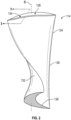
- FIG. 2 An enlarged perspective view of an exemplary embodiment of a gas turbine blade in accordance with the disclosure is shown in Fig. 2 .
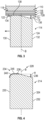
- FIGs. 3-6 Other embodiments of gas turbine blades in accordance with the disclosure, or aspects thereof, are provided in Figs. 3-6 , as will be described.
- the systems and methods described herein can be used to enable blades, e.g. nickel blades with or without any coating, to be used in abradable seal systems for gas turbine engines.
- FIG. 1 schematically shows a gas turbine engine 100 including (in serial flow communication) a fan 102, a compressor 104, a combustor 106, and a turbine 108.
- Gas turbine engine 100 is circumferentially disposed about an engine centerline axis A.
- Gas turbine engine 100 includes an engine case 110 and an integrally bladed rotor 111 having a hub 112 with a plurality of blades 114 radially inward from case 110.
- the plurality of blades 114 being integrally formed with the hub 112 in order to form a single component, the plurality of blades projecting integrally and radially outward from hub 112 for rotation about centerline axis A.
- blade 114 of the integrally bladed rotor 111 includes a blade body 124 integrally formed with the hub 112 and radially extends from the hub 112 to a blade tip surface 128 along a longitudinal axis B.
- Blade body 124 defines a pressure side 130 and a suction side 132.
- blade body 124 includes a cutting edge 134 defined between tip surface 128 of blade body 124 and pressure side 130 of blade body 124.
- Cutting edge 134 is configured to abrade a portion of an abradable liner 116, e.g. a seal section, of case 110.
- abradable liner 116 e.g. a seal section
- abradable liner 116 material is removed by the cutting action of cutting edge 134. It is contemplated that the reduced friction energy consumption as compared with traditional blades tends to reduce heat generation during rubbing of abradable liner 116 and improves the life of the integrally bladed rotor 111.
- blade 114 tends to reduce costs as compared with CBN tipped blades used in traditional seal systems because no CBN tipping is required for blade 114.
- blade 114 can rub harder abradable layers, e.g. abradable liner 116, than traditional CBN tipped blades, therein increasing efficiency and engine performance, notably in the high-pressure compressor (HPC) section 104 of gas turbine 100.
- HPC high-pressure compressor
- the pressure and temperature are higher in HPC section 104 therefore any clearance/gap reduction typically have a higher impact on efficiency improvements.
- abradables with high temperature capability such as nickel and cobalt based materials, are often needed which tend to make it harder to abrade than other abradables found in other turbine sections.
- abradable liner 116 is located between the blade 114 and an inner surface 118 of engine case 110.
- Abradable liner 116 includes a layer of rub material 120 disposed on an inner diameter 122 of abradable liner 116.
- blade tip surface 128 includes a chamfered surface 136 between pressure side 130 and suction side 132 of blade body 124 that tapers toward the hub 112 in a direction from pressure side 130 to suction side 132.
- the chamfered surface 136 reduces the width of contact of the blade tip surface 128 with the rub material 120.
- Blade tip surface 128 includes a land 138 between pressure side 130 and chamfered surface 136.
- a portion of land 138 is at a ninety degree angle with respect to a portion of pressure side 130.
- the angle between land 138 and pressure side 130 is shown and described herein as approximately ninety degrees, the angle can vary depending on the application. For example, a smaller angle tends to increase cutting capability, but there may be a trade-off of reduced cutting edge strength.
- a relief angle ⁇ between land 138 and chamfered surface 136 can range from 2 to 6 degrees. Relief angle ⁇ reduces the contact between blade tip surface 128 and abradable liner 116, tending to reduce friction force and frictional heat generation as compared to traditional blades.
- cutting edge 134 of blade body 124 is positioned proximate an inner diameter 121 of layer of rub material 120 for abrading layer of rub material 120 during circumferential movement of cutting edge 134 as blade body 124 rotates about centerline axis A, shown in Fig. 1 , as indicated schematically by the arrow.
- blade 214 is similar to blade 114.
- cutting edge 234 of blade 214 defines an arcuate portion 240 transitioning between pressure side 230 and land 238 of blade tip surface 228.
- Blade tip surface 228 also includes a coating 246, described in further detail below.
- arcuate portion 240 can be stronger than a sharp cutting edge, but there may be a trade-off of increased frictional forces and higher energy tending to cause increased heat generation.
- blade 314 is similar to blade 114.
- Cutting edge 334 of blade 314 includes a projection portion 342.
- Projection portion 342 extends from pressure side 330 of blade body 324, e.g. extending left as oriented in Fig. 5 .
- An angle ⁇ between pressure side 330 and projection portion 342, e.g. rake angle, can range from 0 to 4 degrees, and/or can be a variety of suitable angles depending on the given application.
- the larger angle ⁇ is, the sharper and more efficient cutting edge 334 can be, tending to require less force to cut through an abradable liner, e.g. abradable liner 116, but there may be a trade-off of reduced cutting edge 334 strength.
- Blade tip surface 328 also includes a coating 346, described in further detail below.
- blade 414 is substantially similar to blade 114.
- Blade 414 includes asperities or raised material such as cutting points 444 extending axially from blade tip surface 428 along longitudinal axis B. Cutting points are disposed on land 438 of blade tip surface 428.
- cutting points 444 can also be disposed on lands 138, 238 and 338 of blades 114, 214 and 314, respectively.
- abradable liner e.g. abradable liner 116
- blades 214, 314 and 414 include a coating 246, 346 and 446 disposed on a portion of blade tip surfaces 228, 328, and 428.
- the coating 246, 346 and 446 may be a hard anodize or thin film coating that does cover the entire portion of blade tip surfaces 228, 328, and 428.
- the coating 246, 346 and 446 may be disposed only on the cutting edge 134, 234, 334, and 434.
- the coating 246, 346 and 446 may be disposed on a thin area between blade tip surface 128, 228, 328, and 428 and pressure side 130, 230, 330, and 430 and be provided instead of the cutting edge .
- the coating 246, 346, and 446 can include abrasive particles or an abrasive grit, retained in a matrix material.
- the abrasive particles / abrasive grit may extend above or beyond the matrix material reducing the contact area to reduce the cutting load and heat between the cutting features and the abradable liner 116 therefore improving the life of the blades of the integrally bladed rotor.
- the abrasive particles can include TiN, TiCN, TiAlN, Al 2 O 3 , carbide particles, diamond, CBN and/or any other suitable coating for machining high strength aerospace alloys.
- the CBN coating varies from CBN abrasive tipping in that the CBN abrasives are typically brazed or plated on the tips of the blades, while the CBN coating is a thin layer, in the range of microns, on the blade tip, similar to a coated cutting tool edge.
- Coatings 246, 346 and 446 tend to reduce the wearing away of blade material, e.g. a nickel alloy material, during rubbing. As shown in Fig. 6 , coating 446 is disposed only on a portion of blade tip surface 428 that includes cutting points 444.
- blade 414 is shown with coating 446 only on cutting points 444, coating 446 can be applied directly to a cutting edge, e.g. cutting edge 134, of a blade, e.g. blade 114, similar to coatings 246 and 346 shown in Figs. 4 and 5 . It is also contemplated that other suitable coatings can be applied to blade tip surfaces 128, 228, 328 and 428 depending on where blades 114, 214, 314 and 414 are being used in the turbine engine.
- a method for manufacturing an integrally bladed rotor includes forming an airfoil, e.g. blade bodies 124, 224, 324 and 424, extending from the hub 112 towards an opposed tip surface, e.g. tip surfaces 128, 228, 328 and 428, along a longitudinal axis, e.g. longitudinal axis B, wherein the airfoil defines a pressure side, e.g. pressure sides 130, 230, 330 and 430, and a suction side, e.g.
- the cutting edge is configured to abrade a seal section, e.g. abradable liner 116, of an engine case, e.g. engine case 110.
- forming the cutting edge includes either machining or forging a chamfered surface, e.g. chamfered surfaces 136, 236, 336 and 436, between the pressure side and the suction side. Machining and/or forging the chamfered surface includes tapering the chamfered surface toward the blade root in a direction from the pressure side to the suction side. According to the invention, forming the cutting edge includes machining and/or forging an arcuate portion, e.g. arcuate portion 240, between the pressure side and a land. Further, those skilled in the art will also readily appreciate that forming the cutting edge can include machining and/or forging a projection portion, e.g. projection portion 342, extending from the pressure side.
- a chamfered surface e.g. chamfered surfaces 136, 236, 336 and 436
- the method can include forming cutting points, e.g. cutting points 444, in the tip surface.
- the cutting points can be formed by machining, knurling or any other suitable manufacturing process.
- the method can also include coating a portion of the tip surface with a coating material including at least one of TiN, TiCN, TiAlN, Al 2 O 3 , CBN and diamond.
- PVD physical vapor deposition
- CVD chemical vapor deposition
Landscapes
- Engineering & Computer Science (AREA)
- Mechanical Engineering (AREA)
- General Engineering & Computer Science (AREA)
- Structures Of Non-Positive Displacement Pumps (AREA)
Claims (11)
- Rotor à aubage intégral (111), comprenant :une pluralité d'aubes (114 ; 214 ; 314 ; 414) formées d'un seul tenant avec un moyeu (112) en tant que composant unique, chacune de la pluralité d'aubes ayant un corps d'aube (124 ; 324 ; 424) s'étendant à partir du moyeu (112) à une surface de pointe d'aube opposée (128 ; 228 ; 328 ; 428) le long d'un axe longitudinal, dans lequel le corps d'aube (124 ; 324 ; 424) définit un intrados (130 ; 230 ; 330 ; 430) et un extrados (132 ; 232 ; 332 ; 432), et dans lequel le corps d'aube (124 ; 324 ; 424) comporte un bord tranchant (134 ; 234 ; 334 ; 434) défini entre la surface de pointe d'aube (128 ; 228 ; 328 ; 428) du corps d'aube et l'intrados (130 ; 230 ; 330 ; 430) du corps d'aube, dans lequel le bord tranchant (134 ; 234 ; 334 ; 434) est configuré pour abraser une section d'étanchéité (116) d'un carter de moteur (110) ;dans lequel la surface de pointe d'aube (128 ; 228 ; 328 ; 428) comporte une surface chanfreinée (136 ; 236 ; 336 ; 436) entre l'intrados (130 ; 230 ; 330 ; 430) et l'extrados (132 ; 232 ; 332 ; 432) du corps d'aube (124 ; 324 ; 424) qui s'effile vers le moyeu (112) dans une direction allant de l'intrados vers l'extrados ; caractérisé en ce que le bord tranchant (134 ; 234 ; 334 ; 434) définit une partie arquée (240) faisant la transition entre l'intrados (130 ; 230 ; 330 ; 430) et une superficie (138 ; 238 ; 338 ; 438) de la surface de pointe d'aube (128 ; 228 ; 328 ; 428), dans lequel la superficie est située entre l'intrados (130 ; 230 ; 330 ; 430) et la surface chanfreinée (136 ; 236 ; 336 ; 436).
- Rotor à aubage intégral (111) selon la revendication 1, comprenant en outre des points tranchants (444) s'étendant axialement à partir de la surface de pointe d'aube (428) le long de l'axe longitudinal.
- Rotor à aubage intégral (111) selon la revendication 1 ou 2, comprenant en outre un revêtement (246 ; 346 ; 446) disposé sur une partie de la surface de pointe d'aube (128 ; 228 ; 328 ; 428), dans lequel le revêtement (246 ; 346 ; 446) comporte des particules abrasives, les particules abrasives comportant au moins l'un parmi TiN, TiCN, TiAlN, Al2O3, des particules de carbure, du CBN et du diamant, et dans lequel les particules abrasives sont retenues dans un matériau de matrice.
- Rotor à aubage intégral (111) selon la revendication 3 lorsqu'elle dépend de la revendication 2, dans lequel le revêtement (246 ; 346 ; 446) est disposé uniquement sur une partie de la surface de pointe d'aube (128 ; 228 ; 328 ; 428) qui comporte les points tranchants (444).
- Rotor à aubage intégral (111) selon une quelconque revendication précédente, dans lequel le bord tranchant (134 ; 234 ; 334 ; 434) comporte une partie en saillie (342), dans lequel la partie en saillie s'étend à partir de l'intrados (130 ; 230 ; 330 ; 430) du corps d'aube (124 ; 324 ; 424).
- Procédé de fabrication d'un rotor à aubage intégral (111), le procédé comprenant :la formation d'une pluralité de profils aérodynamiques d'un seul tenant avec un moyeu (112) pour former un composant unique, chacun de la pluralité de profils aérodynamiques ayant une surface de pointe opposée (128 ; 228 ; 328 ; 428) par rapport au moyeu s'étendant le long d'un axe longitudinal, dans lequel chacun de la pluralité de profils aérodynamiques définit un intrados (130 ; 230 ; 330 ; 430) et un extrados (132 ; 232 ; 332 ; 432) ; etla formation d'un bord tranchant (134 ; 234 ; 334 ; 434) entre la surface de pointe (128 ; 228 ; 328 ; 428) et l'intrados (130 ; 230 ; 330 ; 430) de chacun de la pluralité de profils aérodynamiques, dans lequel le bord tranchant est configuré pour abraser une section d'étanchéité (116) d'un carter de moteur (110), dans lequel la formation d'un bord tranchant (134 ; 234 ; 334 ; 434) comporte l'usinage et/ou le forgeage d'une partie arquée (240) entre l'intrados (130 ; 230 ; 330 ; 430) et une superficie (138 ; 238 ; 338 ; 438), dans lequel la superficie est située sur la surface de pointe (128 ; 228 ; 328 ; 428) entre l'intrados et une surface chanfreinée (136 ; 236 ; 336 ; 436), et dans lequel la surface chanfreinée se trouve sur la surface de pointe entre l'intrados et l'extrados (132 ; 232 ; 332 ; 432) et s'effile vers le moyeu (112) dans une direction allant de l'intrados vers l'extrados.
- Procédé selon la revendication 6, dans lequel la formation d'un bord tranchant (134 ; 234 ; 334 ; 434) comporte l'usinage et/ou le forgeage de la surface chanfreinée (136 ; 236 ; 336 ; 436) entre l'intrados (130 ; 230 330 ; 430) et l'extrados (132 ; 232 ; 332 ; 432), dans lequel l'usinage et/ou le forgeage de la surface chanfreinée comporte l'effilement de la surface chanfreinée vers le moyeu (112) dans une direction allant de l'intrados vers l'extrados, dans lequel l'usinage de la surface chanfreinée comporte l'usinage de la surface chanfreinée sur la surface de pointe (128 ; 228 ; 328 ; 428).
- Procédé selon la revendication 6 ou 7, dans lequel la formation d'un bord tranchant (134 ; 234 ; 334 ; 434) comporte l'usinage et/ou le forgeage d'une partie en saillie (342) s'étendant à partir de l'intrados (130 ; 230 ; 330 ; 430).
- Procédé selon l'une quelconque des revendications 6 à 8, comprenant en outre la formation de points tranchants (444) dans la surface de la pointe (128 ; 228 ; 328 ; 428), dans lequel les points tranchants s'étendent axialement à partir de la surface de pointe le long de l'axe longitudinal.
- Procédé selon l'une quelconque des revendications 6 à 9, comprenant en outre le revêtement d'une partie de la surface de pointe (128 ; 228 ; 328 ; 428) avec un matériau de revêtement (246 ; 346 ; 446) comportant des particules abrasives, les particules abrasives comprenant au au moins l'un parmi TiN, TiCN, TiAlN, Al2O3, des particules de carbure, du CBN et du diamant, et dans lequel les particules abrasives sont retenues dans un matériau de matrice.
- Moteur à turbine à gaz (100) comprenant :un carter (110) définissant un axe central ;un revêtement abradable (116) disposé radialement vers l'intérieur du carter comportant une couche de matériau de frottement (120) disposée sur un diamètre interne (122) du revêtement abradable ;un rotor à aubage intégral (111) selon l'une quelconque des revendications 1 à 5, ayant un moyeu (112) radialement vers l'intérieur du carter (110) et le revêtement abradable (116) ; etdans lequel la pluralité de corps d'aube (124 ; 324 ; 424) s'étendent radialement vers l'extérieur à partir du moyeu (112) pour une rotation autour de l'axe central, et le bord tranchant (134 ; 234 ; 334 ; 434) de chaque corps d'aube étant positionné à proximité d'un diamètre interne (121) de la couche de matériau de frottement (120) pour abraser la couche de matériau de frottement pendant le mouvement circonférentiel des bords tranchants lorsque les corps d'aube tournent autour de l'axe central.
Applications Claiming Priority (1)
| Application Number | Priority Date | Filing Date | Title |
|---|---|---|---|
| US16/825,610 US11066937B2 (en) | 2014-06-04 | 2020-03-20 | Cutting blade tips |
Publications (2)
| Publication Number | Publication Date |
|---|---|
| EP3882437A1 EP3882437A1 (fr) | 2021-09-22 |
| EP3882437B1 true EP3882437B1 (fr) | 2024-06-19 |
Family
ID=75173033
Family Applications (1)
| Application Number | Title | Priority Date | Filing Date |
|---|---|---|---|
| EP21164108.9A Active EP3882437B1 (fr) | 2020-03-20 | 2021-03-22 | Rotor à aubage intégral, moteur à turbine à gaz et procédé de fabrication d'un rotor à aubage intégral |
Country Status (1)
| Country | Link |
|---|---|
| EP (1) | EP3882437B1 (fr) |
Family Cites Families (6)
| Publication number | Priority date | Publication date | Assignee | Title |
|---|---|---|---|---|
| FR2891594A1 (fr) * | 2005-09-30 | 2007-04-06 | Snecma Sa | Aube de compresseur a sommet chanfreine |
| US8657570B2 (en) * | 2009-06-30 | 2014-02-25 | General Electric Company | Rotor blade with reduced rub loading |
| EP2309097A1 (fr) * | 2009-09-30 | 2011-04-13 | Siemens Aktiengesellschaft | Profil et aube directrice, aube rotorique, turbine à gaz et turbomachine associées |
| US9932839B2 (en) * | 2014-06-04 | 2018-04-03 | United Technologies Corporation | Cutting blade tips |
| GB201900961D0 (en) * | 2019-01-24 | 2019-03-13 | Rolls Royce Plc | Fan blade |
| US11225874B2 (en) * | 2019-12-20 | 2022-01-18 | Raytheon Technologies Corporation | Turbine engine rotor blade with castellated tip surface |
-
2021
- 2021-03-22 EP EP21164108.9A patent/EP3882437B1/fr active Active
Also Published As
| Publication number | Publication date |
|---|---|
| EP3882437A1 (fr) | 2021-09-22 |
Similar Documents
| Publication | Publication Date | Title |
|---|---|---|
| US10711622B2 (en) | Cutting blade tips | |
| US5932356A (en) | Abrasive/abradable gas path seal system | |
| EP3623082B1 (fr) | Procédé de production d'une pointe abrasive pour une aube de turbine | |
| US10472729B2 (en) | Abrasive tip blade manufacture methods | |
| US9598972B2 (en) | Abradable turbine air seal | |
| US20060171813A1 (en) | Turbine blade tip and shroud clearance control coating system | |
| EP3611342A2 (fr) | Revêtement pour améliorer la résistance à l'd'oxydation et à la corrosion de système de pointe abrasive | |
| EP3034809B1 (fr) | Composant de moteur à turbine à gaz avec surface abrasive formée par usinage à décharge électrique | |
| EP3318719B1 (fr) | Rotor de turbomachine avec aubes revêtues | |
| US7749565B2 (en) | Method for applying and dimensioning an abradable coating | |
| EP3683017A2 (fr) | Revêtement abrasif pour systèmes mécaniques à haute température et systèmes mécaniques à haute température avec un revêtement abrasif | |
| US10927685B2 (en) | Coating to improve oxidation and corrosion resistance of abrasive tip system | |
| US11066937B2 (en) | Cutting blade tips | |
| EP3882437B1 (fr) | Rotor à aubage intégral, moteur à turbine à gaz et procédé de fabrication d'un rotor à aubage intégral | |
| US12359573B2 (en) | Blade for a turbomachine including blade tip armor and an erosion protection layer, and method for manufacturing same | |
| EP3611350B1 (fr) | Pointes de lame de turbine abrasives présentant une meilleure résistance à l'oxydation | |
| JP4096301B2 (ja) | 動翼及びそのコーティング方法 | |
| JPH08303204A (ja) | ガスタービンの動翼シール構造 | |
| JP2025508198A (ja) | ロータブレード、ロータブレードの製造方法、およびガスタービンエンジン | |
| CN102536889A (zh) | 带有柔性顶端元件的压缩机叶片和其过程 |
Legal Events
| Date | Code | Title | Description |
|---|---|---|---|
| PUAI | Public reference made under article 153(3) epc to a published international application that has entered the european phase |
Free format text: ORIGINAL CODE: 0009012 |
|
| STAA | Information on the status of an ep patent application or granted ep patent |
Free format text: STATUS: THE APPLICATION HAS BEEN PUBLISHED |
|
| AK | Designated contracting states |
Kind code of ref document: A1 Designated state(s): AL AT BE BG CH CY CZ DE DK EE ES FI FR GB GR HR HU IE IS IT LI LT LU LV MC MK MT NL NO PL PT RO RS SE SI SK SM TR |
|
| STAA | Information on the status of an ep patent application or granted ep patent |
Free format text: STATUS: REQUEST FOR EXAMINATION WAS MADE |
|
| 17P | Request for examination filed |
Effective date: 20220322 |
|
| RBV | Designated contracting states (corrected) |
Designated state(s): AL AT BE BG CH CY CZ DE DK EE ES FI FR GB GR HR HU IE IS IT LI LT LU LV MC MK MT NL NO PL PT RO RS SE SI SK SM TR |
|
| STAA | Information on the status of an ep patent application or granted ep patent |
Free format text: STATUS: EXAMINATION IS IN PROGRESS |
|
| 17Q | First examination report despatched |
Effective date: 20230510 |
|
| RAP3 | Party data changed (applicant data changed or rights of an application transferred) |
Owner name: RTX CORPORATION |
|
| GRAP | Despatch of communication of intention to grant a patent |
Free format text: ORIGINAL CODE: EPIDOSNIGR1 |
|
| STAA | Information on the status of an ep patent application or granted ep patent |
Free format text: STATUS: GRANT OF PATENT IS INTENDED |
|
| RIC1 | Information provided on ipc code assigned before grant |
Ipc: F01D 5/34 20060101ALI20231218BHEP Ipc: F01D 11/12 20060101ALI20231218BHEP Ipc: F01D 5/20 20060101AFI20231218BHEP |
|
| INTG | Intention to grant announced |
Effective date: 20240111 |
|
| GRAS | Grant fee paid |
Free format text: ORIGINAL CODE: EPIDOSNIGR3 |
|
| GRAA | (expected) grant |
Free format text: ORIGINAL CODE: 0009210 |
|
| STAA | Information on the status of an ep patent application or granted ep patent |
Free format text: STATUS: THE PATENT HAS BEEN GRANTED |
|
| AK | Designated contracting states |
Kind code of ref document: B1 Designated state(s): AL AT BE BG CH CY CZ DE DK EE ES FI FR GB GR HR HU IE IS IT LI LT LU LV MC MK MT NL NO PL PT RO RS SE SI SK SM TR |
|
| REG | Reference to a national code |
Ref country code: GB Ref legal event code: FG4D |
|
| REG | Reference to a national code |
Ref country code: CH Ref legal event code: EP |
|
| REG | Reference to a national code |
Ref country code: DE Ref legal event code: R096 Ref document number: 602021014503 Country of ref document: DE |
|
| PG25 | Lapsed in a contracting state [announced via postgrant information from national office to epo] |
Ref country code: BG Free format text: LAPSE BECAUSE OF FAILURE TO SUBMIT A TRANSLATION OF THE DESCRIPTION OR TO PAY THE FEE WITHIN THE PRESCRIBED TIME-LIMIT Effective date: 20240619 |
|
| PG25 | Lapsed in a contracting state [announced via postgrant information from national office to epo] |
Ref country code: FI Free format text: LAPSE BECAUSE OF FAILURE TO SUBMIT A TRANSLATION OF THE DESCRIPTION OR TO PAY THE FEE WITHIN THE PRESCRIBED TIME-LIMIT Effective date: 20240619 Ref country code: HR Free format text: LAPSE BECAUSE OF FAILURE TO SUBMIT A TRANSLATION OF THE DESCRIPTION OR TO PAY THE FEE WITHIN THE PRESCRIBED TIME-LIMIT Effective date: 20240619 |
|
| REG | Reference to a national code |
Ref country code: LT Ref legal event code: MG9D |
|
| PG25 | Lapsed in a contracting state [announced via postgrant information from national office to epo] |
Ref country code: GR Free format text: LAPSE BECAUSE OF FAILURE TO SUBMIT A TRANSLATION OF THE DESCRIPTION OR TO PAY THE FEE WITHIN THE PRESCRIBED TIME-LIMIT Effective date: 20240920 |
|
| REG | Reference to a national code |
Ref country code: NL Ref legal event code: MP Effective date: 20240619 |
|
| PG25 | Lapsed in a contracting state [announced via postgrant information from national office to epo] |
Ref country code: LV Free format text: LAPSE BECAUSE OF FAILURE TO SUBMIT A TRANSLATION OF THE DESCRIPTION OR TO PAY THE FEE WITHIN THE PRESCRIBED TIME-LIMIT Effective date: 20240619 |
|
| PG25 | Lapsed in a contracting state [announced via postgrant information from national office to epo] |
Ref country code: NO Free format text: LAPSE BECAUSE OF FAILURE TO SUBMIT A TRANSLATION OF THE DESCRIPTION OR TO PAY THE FEE WITHIN THE PRESCRIBED TIME-LIMIT Effective date: 20240919 Ref country code: LV Free format text: LAPSE BECAUSE OF FAILURE TO SUBMIT A TRANSLATION OF THE DESCRIPTION OR TO PAY THE FEE WITHIN THE PRESCRIBED TIME-LIMIT Effective date: 20240619 Ref country code: HR Free format text: LAPSE BECAUSE OF FAILURE TO SUBMIT A TRANSLATION OF THE DESCRIPTION OR TO PAY THE FEE WITHIN THE PRESCRIBED TIME-LIMIT Effective date: 20240619 Ref country code: GR Free format text: LAPSE BECAUSE OF FAILURE TO SUBMIT A TRANSLATION OF THE DESCRIPTION OR TO PAY THE FEE WITHIN THE PRESCRIBED TIME-LIMIT Effective date: 20240920 Ref country code: FI Free format text: LAPSE BECAUSE OF FAILURE TO SUBMIT A TRANSLATION OF THE DESCRIPTION OR TO PAY THE FEE WITHIN THE PRESCRIBED TIME-LIMIT Effective date: 20240619 Ref country code: BG Free format text: LAPSE BECAUSE OF FAILURE TO SUBMIT A TRANSLATION OF THE DESCRIPTION OR TO PAY THE FEE WITHIN THE PRESCRIBED TIME-LIMIT Effective date: 20240619 Ref country code: RS Free format text: LAPSE BECAUSE OF FAILURE TO SUBMIT A TRANSLATION OF THE DESCRIPTION OR TO PAY THE FEE WITHIN THE PRESCRIBED TIME-LIMIT Effective date: 20240919 |
|
| PG25 | Lapsed in a contracting state [announced via postgrant information from national office to epo] |
Ref country code: NL Free format text: LAPSE BECAUSE OF FAILURE TO SUBMIT A TRANSLATION OF THE DESCRIPTION OR TO PAY THE FEE WITHIN THE PRESCRIBED TIME-LIMIT Effective date: 20240619 |
|
| REG | Reference to a national code |
Ref country code: AT Ref legal event code: MK05 Ref document number: 1696030 Country of ref document: AT Kind code of ref document: T Effective date: 20240619 |
|
| PG25 | Lapsed in a contracting state [announced via postgrant information from national office to epo] |
Ref country code: NL Free format text: LAPSE BECAUSE OF FAILURE TO SUBMIT A TRANSLATION OF THE DESCRIPTION OR TO PAY THE FEE WITHIN THE PRESCRIBED TIME-LIMIT Effective date: 20240619 |
|
| PG25 | Lapsed in a contracting state [announced via postgrant information from national office to epo] |
Ref country code: PT Free format text: LAPSE BECAUSE OF FAILURE TO SUBMIT A TRANSLATION OF THE DESCRIPTION OR TO PAY THE FEE WITHIN THE PRESCRIBED TIME-LIMIT Effective date: 20241021 |
|
| PG25 | Lapsed in a contracting state [announced via postgrant information from national office to epo] |
Ref country code: PT Free format text: LAPSE BECAUSE OF FAILURE TO SUBMIT A TRANSLATION OF THE DESCRIPTION OR TO PAY THE FEE WITHIN THE PRESCRIBED TIME-LIMIT Effective date: 20241021 |
|
| PG25 | Lapsed in a contracting state [announced via postgrant information from national office to epo] |
Ref country code: PL Free format text: LAPSE BECAUSE OF FAILURE TO SUBMIT A TRANSLATION OF THE DESCRIPTION OR TO PAY THE FEE WITHIN THE PRESCRIBED TIME-LIMIT Effective date: 20240619 |
|
| PG25 | Lapsed in a contracting state [announced via postgrant information from national office to epo] |
Ref country code: EE Free format text: LAPSE BECAUSE OF FAILURE TO SUBMIT A TRANSLATION OF THE DESCRIPTION OR TO PAY THE FEE WITHIN THE PRESCRIBED TIME-LIMIT Effective date: 20240619 |
|
| PG25 | Lapsed in a contracting state [announced via postgrant information from national office to epo] |
Ref country code: IS Free format text: LAPSE BECAUSE OF FAILURE TO SUBMIT A TRANSLATION OF THE DESCRIPTION OR TO PAY THE FEE WITHIN THE PRESCRIBED TIME-LIMIT Effective date: 20241019 Ref country code: AT Free format text: LAPSE BECAUSE OF FAILURE TO SUBMIT A TRANSLATION OF THE DESCRIPTION OR TO PAY THE FEE WITHIN THE PRESCRIBED TIME-LIMIT Effective date: 20240619 |
|
| PG25 | Lapsed in a contracting state [announced via postgrant information from national office to epo] |
Ref country code: CZ Free format text: LAPSE BECAUSE OF FAILURE TO SUBMIT A TRANSLATION OF THE DESCRIPTION OR TO PAY THE FEE WITHIN THE PRESCRIBED TIME-LIMIT Effective date: 20240619 |
|
| PG25 | Lapsed in a contracting state [announced via postgrant information from national office to epo] |
Ref country code: RO Free format text: LAPSE BECAUSE OF FAILURE TO SUBMIT A TRANSLATION OF THE DESCRIPTION OR TO PAY THE FEE WITHIN THE PRESCRIBED TIME-LIMIT Effective date: 20240619 Ref country code: SK Free format text: LAPSE BECAUSE OF FAILURE TO SUBMIT A TRANSLATION OF THE DESCRIPTION OR TO PAY THE FEE WITHIN THE PRESCRIBED TIME-LIMIT Effective date: 20240619 |
|
| PG25 | Lapsed in a contracting state [announced via postgrant information from national office to epo] |
Ref country code: ES Free format text: LAPSE BECAUSE OF FAILURE TO SUBMIT A TRANSLATION OF THE DESCRIPTION OR TO PAY THE FEE WITHIN THE PRESCRIBED TIME-LIMIT Effective date: 20240619 Ref country code: SM Free format text: LAPSE BECAUSE OF FAILURE TO SUBMIT A TRANSLATION OF THE DESCRIPTION OR TO PAY THE FEE WITHIN THE PRESCRIBED TIME-LIMIT Effective date: 20240619 |
|
| PG25 | Lapsed in a contracting state [announced via postgrant information from national office to epo] |
Ref country code: SM Free format text: LAPSE BECAUSE OF FAILURE TO SUBMIT A TRANSLATION OF THE DESCRIPTION OR TO PAY THE FEE WITHIN THE PRESCRIBED TIME-LIMIT Effective date: 20240619 Ref country code: SK Free format text: LAPSE BECAUSE OF FAILURE TO SUBMIT A TRANSLATION OF THE DESCRIPTION OR TO PAY THE FEE WITHIN THE PRESCRIBED TIME-LIMIT Effective date: 20240619 Ref country code: RO Free format text: LAPSE BECAUSE OF FAILURE TO SUBMIT A TRANSLATION OF THE DESCRIPTION OR TO PAY THE FEE WITHIN THE PRESCRIBED TIME-LIMIT Effective date: 20240619 Ref country code: PL Free format text: LAPSE BECAUSE OF FAILURE TO SUBMIT A TRANSLATION OF THE DESCRIPTION OR TO PAY THE FEE WITHIN THE PRESCRIBED TIME-LIMIT Effective date: 20240619 Ref country code: IS Free format text: LAPSE BECAUSE OF FAILURE TO SUBMIT A TRANSLATION OF THE DESCRIPTION OR TO PAY THE FEE WITHIN THE PRESCRIBED TIME-LIMIT Effective date: 20241019 Ref country code: ES Free format text: LAPSE BECAUSE OF FAILURE TO SUBMIT A TRANSLATION OF THE DESCRIPTION OR TO PAY THE FEE WITHIN THE PRESCRIBED TIME-LIMIT Effective date: 20240619 Ref country code: EE Free format text: LAPSE BECAUSE OF FAILURE TO SUBMIT A TRANSLATION OF THE DESCRIPTION OR TO PAY THE FEE WITHIN THE PRESCRIBED TIME-LIMIT Effective date: 20240619 Ref country code: CZ Free format text: LAPSE BECAUSE OF FAILURE TO SUBMIT A TRANSLATION OF THE DESCRIPTION OR TO PAY THE FEE WITHIN THE PRESCRIBED TIME-LIMIT Effective date: 20240619 Ref country code: AT Free format text: LAPSE BECAUSE OF FAILURE TO SUBMIT A TRANSLATION OF THE DESCRIPTION OR TO PAY THE FEE WITHIN THE PRESCRIBED TIME-LIMIT Effective date: 20240619 |
|
| PG25 | Lapsed in a contracting state [announced via postgrant information from national office to epo] |
Ref country code: IT Free format text: LAPSE BECAUSE OF FAILURE TO SUBMIT A TRANSLATION OF THE DESCRIPTION OR TO PAY THE FEE WITHIN THE PRESCRIBED TIME-LIMIT Effective date: 20240619 |
|
| REG | Reference to a national code |
Ref country code: DE Ref legal event code: R097 Ref document number: 602021014503 Country of ref document: DE |
|
| PG25 | Lapsed in a contracting state [announced via postgrant information from national office to epo] |
Ref country code: DK Free format text: LAPSE BECAUSE OF FAILURE TO SUBMIT A TRANSLATION OF THE DESCRIPTION OR TO PAY THE FEE WITHIN THE PRESCRIBED TIME-LIMIT Effective date: 20240619 |
|
| PLBE | No opposition filed within time limit |
Free format text: ORIGINAL CODE: 0009261 |
|
| STAA | Information on the status of an ep patent application or granted ep patent |
Free format text: STATUS: NO OPPOSITION FILED WITHIN TIME LIMIT |
|
| 26N | No opposition filed |
Effective date: 20250320 |
|
| PG25 | Lapsed in a contracting state [announced via postgrant information from national office to epo] |
Ref country code: SE Free format text: LAPSE BECAUSE OF FAILURE TO SUBMIT A TRANSLATION OF THE DESCRIPTION OR TO PAY THE FEE WITHIN THE PRESCRIBED TIME-LIMIT Effective date: 20240619 |
|
| PG25 | Lapsed in a contracting state [announced via postgrant information from national office to epo] |
Ref country code: MC Free format text: LAPSE BECAUSE OF FAILURE TO SUBMIT A TRANSLATION OF THE DESCRIPTION OR TO PAY THE FEE WITHIN THE PRESCRIBED TIME-LIMIT Effective date: 20240619 |
|
| REG | Reference to a national code |
Ref country code: CH Ref legal event code: H13 Free format text: ST27 STATUS EVENT CODE: U-0-0-H10-H13 (AS PROVIDED BY THE NATIONAL OFFICE) Effective date: 20251023 |
|
| PG25 | Lapsed in a contracting state [announced via postgrant information from national office to epo] |
Ref country code: LU Free format text: LAPSE BECAUSE OF NON-PAYMENT OF DUE FEES Effective date: 20250322 |
|
| REG | Reference to a national code |
Ref country code: BE Ref legal event code: MM Effective date: 20250331 |
|
| PG25 | Lapsed in a contracting state [announced via postgrant information from national office to epo] |
Ref country code: BE Free format text: LAPSE BECAUSE OF NON-PAYMENT OF DUE FEES Effective date: 20250331 |
|
| PG25 | Lapsed in a contracting state [announced via postgrant information from national office to epo] |
Ref country code: CH Free format text: LAPSE BECAUSE OF NON-PAYMENT OF DUE FEES Effective date: 20250331 |
|
| PG25 | Lapsed in a contracting state [announced via postgrant information from national office to epo] |
Ref country code: IE Free format text: LAPSE BECAUSE OF NON-PAYMENT OF DUE FEES Effective date: 20250322 |
|
| PGFP | Annual fee paid to national office [announced via postgrant information from national office to epo] |
Ref country code: GB Payment date: 20260219 Year of fee payment: 6 |
|
| PGFP | Annual fee paid to national office [announced via postgrant information from national office to epo] |
Ref country code: DE Payment date: 20260219 Year of fee payment: 6 |
|
| PGFP | Annual fee paid to national office [announced via postgrant information from national office to epo] |
Ref country code: FR Payment date: 20260220 Year of fee payment: 6 |