EP3882486A1 - Butée d'arrêt de réglage de course à double écrou - Google Patents
Butée d'arrêt de réglage de course à double écrou Download PDFInfo
- Publication number
- EP3882486A1 EP3882486A1 EP20275060.0A EP20275060A EP3882486A1 EP 3882486 A1 EP3882486 A1 EP 3882486A1 EP 20275060 A EP20275060 A EP 20275060A EP 3882486 A1 EP3882486 A1 EP 3882486A1
- Authority
- EP
- European Patent Office
- Prior art keywords
- nut
- rod
- shaft
- hook
- stop
- Prior art date
- Legal status (The legal status is an assumption and is not a legal conclusion. Google has not performed a legal analysis and makes no representation as to the accuracy of the status listed.)
- Pending
Links
Images
Classifications
-
- F—MECHANICAL ENGINEERING; LIGHTING; HEATING; WEAPONS; BLASTING
- F16—ENGINEERING ELEMENTS AND UNITS; GENERAL MEASURES FOR PRODUCING AND MAINTAINING EFFECTIVE FUNCTIONING OF MACHINES OR INSTALLATIONS; THERMAL INSULATION IN GENERAL
- F16H—GEARING
- F16H25/00—Gearings comprising primarily only cams, cam-followers and screw-and-nut mechanisms
- F16H25/18—Gearings comprising primarily only cams, cam-followers and screw-and-nut mechanisms for conveying or interconverting oscillating or reciprocating motions
- F16H25/20—Screw mechanisms
- F16H25/2015—Means specially adapted for stopping actuators in the end position; Position sensing means
-
- F—MECHANICAL ENGINEERING; LIGHTING; HEATING; WEAPONS; BLASTING
- F16—ENGINEERING ELEMENTS AND UNITS; GENERAL MEASURES FOR PRODUCING AND MAINTAINING EFFECTIVE FUNCTIONING OF MACHINES OR INSTALLATIONS; THERMAL INSULATION IN GENERAL
- F16H—GEARING
- F16H25/00—Gearings comprising primarily only cams, cam-followers and screw-and-nut mechanisms
- F16H25/18—Gearings comprising primarily only cams, cam-followers and screw-and-nut mechanisms for conveying or interconverting oscillating or reciprocating motions
- F16H25/20—Screw mechanisms
- F16H25/24—Elements essential to such mechanisms, e.g. screws, nuts
-
- F—MECHANICAL ENGINEERING; LIGHTING; HEATING; WEAPONS; BLASTING
- F16—ENGINEERING ELEMENTS AND UNITS; GENERAL MEASURES FOR PRODUCING AND MAINTAINING EFFECTIVE FUNCTIONING OF MACHINES OR INSTALLATIONS; THERMAL INSULATION IN GENERAL
- F16H—GEARING
- F16H25/00—Gearings comprising primarily only cams, cam-followers and screw-and-nut mechanisms
- F16H25/18—Gearings comprising primarily only cams, cam-followers and screw-and-nut mechanisms for conveying or interconverting oscillating or reciprocating motions
- F16H25/20—Screw mechanisms
- F16H2025/204—Axial sliding means, i.e. for rotary support and axial guiding of nut or screw shaft
Definitions
- the present disclosure relates to an over travel stop unit for actuator valves.
- the present disclosure relates to an assembly and a method of adjustment for an over travel stop unit.
- Actuators require accurate travel stop adjustments at ends of the stroke to obtain optimal performance and valve seat life.
- an actuator system includes travel stops and components specific to that particular actuator system.
- the length of the screw will be specific to the stroke requirement of that particular actuator system.
- a travel stop assembly for an actuator.
- the travel stop assembly includes a housing, a shaft provided along a longitudinal axis.
- the shaft has a first end and a second end.
- the travel stop assembly also includes a first nut and a second nut provided on the shaft, wherein there is provided a first gap between the first nut and the second nut.
- the travel stop assembly also includes a second gap provided between the second nut and the first end of the shaft, and means for adjusting the position of the first nut and the second nut such that the second gap is maintained.
- the means for adjusting the position of the first nut and the second nut may further include a first rod and a second rod provided at an inner wall of the housing.
- the first nut may include a first hook and a second hook that are configured to engage the first rod and the second rod.
- the second nut may include a first hook and a second hook that are configured to engage the first rod and the second rod.
- the first rod and second rod may be parallel to the shaft, and the first rod may be opposite the second rod.
- the travel stop assembly may further include a first end stop provided at the second end of the shaft, a second end stop provided on one side of the first nut, a third end stop provided at the first end of the shaft, and a fourth end stop provided on one side of the second nut.
- the second gap may be provided between the third end stop and the fourth end stop.
- the second end stop may include at least one protrusion that extends radially away from the surface of the first nut along the longitudinal axis.
- the fourth end stop may also include at least one protrusion that extends radially away from the surface of the second nut along the longitudinal axis.
- the shaft is a threaded screw.
- actuator assembly including the travel stop assembly as described above.
- a method of adjusting a resultant stroke gap of a travel stop unit which includes providing a shaft along a longitudinal axis, the shaft having a first end and a second end, providing a first nut and a second nut on the shaft, providing a first gap between the first nut and the second nut, providing a second gap between the second nut and the first end of the shaft, and adjusting the position of the first nut and the second nut such that the second gap is maintained in a housing.
- adjusting the position of the first nut and the second nut may further include providing a first rod and a second rod at an inner wall of the housing, and engaging a first hook and a second hook of the first nut to the first rod and the second rod, and engaging a first hook and a second hook of the second nut to the first rod and the second rod.
- the first rod and second rod may be parallel to the shaft, and the first rod may be opposite the second rod.
- the method may further include providing a first end stop at the second end of the shaft, providing a second end stop on one side of the first nut, providing a third end stop at the first end of the shaft, and providing a fourth end stop on one side of the second nut.
- the second gap may be provided between the third end stop and the fourth end stop.
- the second end stop may further comprise at least one protrusion that extends radially away from the surface of the first nut along the longitudinal axis
- the fourth end stop may further comprise at least one protrusion that extends radially away from the surface of the second nut along the longitudinal axis.
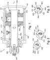
- the assembly 10 may also be known as an over travel stop unit.
- the assembly 10 may include a housing 100 to house various components that allow for adjustment of the travel stop.
- the assembly 10 may have a longitudinal axis A running through the centre of the assembly 10 and the housing 100 may be provided about this longitudinal axis A.
- a shaft for example, a threaded screw 200 along the longitudinal axis A of the assembly 10.
- a first nut 201 and a second nut 202 can be received on the threaded screw 200.
- An adjustment gap A g may be formed between the first nut 201 and the second nut 202. This may be done manually by an engineer before incorporating the components for the assembly 10 in the housing 100.
- a first rod 101 may be provided at an inner wall 100' of the housing 100.
- the first rod 101 runs parallel to the threaded screw 200.
- a second rod 102 may be provided at the inner wall 100' of the housing 100, opposite the first rod 101.
- the first rod 101 and the second rod 102 are cylindrical.
- other geometries could be used as well to allow the first nut 201 and second nut 202 to engage with the first rod 101 and second rod 102, as described in more detail below.
- the threaded screw 200 has a first end 203 and a second end 204.
- a first end stop 214 Provided at the second end 204 of the threaded screw 200 is a first end stop 214.
- a second end stop 211 Provided on one side of the first nut 201 is a second end stop 211 that faces the first end stop 214 (i.e., the second end stop 211 is to the right hand side of the first nut 201).
- Provided on one side of the second nut 202 is a fourth end stop 212 that faces the third end stop 213 (i.e., the fourth end stop 212 is provided on the left hand side of the second nut 202).
- the gap between the third end stop 213 and the fourth end stop 212 is designated by the reference S g and refers to the resultant stroke gap.
- a user can adjust the resultant stroke gap S g by placing the first nut 201 and second nut 202 at the desired positions on the threaded screw 200. The user can then engage the threaded screw 200 in the housing 100.
- An axial screw 301 is applied to the threaded screw 200 to maintain the position of the threaded screw 200 in the housing 100.
- an adjustment means 300 which may be in the form of an exposed outer spline of the threaded screw 200. This is described in more detail below.
- the first nut 201 and the second nut 202 are shown.
- the first nut 201 may include a first hook 221 that extends radially from the overall surface of the first nut 201.
- the first nut 201 may also include a second hook 222 that also extends radially from the overall surface of the first nut 201.
- the first hook 221 of the first nut 201 therefore, provides a first hook surface 221' that can interact with one of the first rod 101 or the second rod 102 (as shown in Figure 1 ), in use.
- the first hook surface 221' is perpendicular to the overall surface of the first nut 201 and is configured to receive one of the first rod 101 or the second rod 102 (e.g. it includes a recess (not shown) that is sized and shaped to receive either the first rod 101 or the second rod 102).
- the second hook 222 also may provide a second hook surface 222' that can interact with one of the first rod 101 or the second rod 102, in use.
- the second hook surface 222' is perpendicular to the overall surface of the first nut 201 and is configured to receive one of the first rod 101 or the second rod 102 (e.g. it includes a recess (not shown) that is sized and shaped to receive either the first rod 101 or the second rod 102).
- the first nut 201 may have a first protrusion 223 and a second protrusion 224 that extend radially from the surface of the first nut 201 along the longitudinal axis.
- the first protrusion 223 and second protrusion 224 may therefore act as the second end stop 211 shown in Figure 1 .
- the second nut 202 may include a first hook 231 that extends radially from the surface of the second nut 202.
- the second nut 202 may also include a second hook 232 that also extends radially from the surface of the second nut 202.
- the first hook 231 of the second nut 202 therefore, provides a first hook surface 231' that can interact with one of the first rod 101 or the second rod 102 (as shown in Figure 1 ), in use.
- the first hook surface 231' is perpendicular to the overall surface of the second nut 202 and is configured to receive one of the first rod 101 or the second rod 102 (e.g.
- the second hook 232 also may provide a second hook surface 232' that can interact with one of the first rod 101 or the second rod 102, in use.
- the second hook surface 232' is perpendicular to the overall surface of the second nut 202 and is configured to receive one of the first rod 101 or the second rod 102 (e.g. it includes a recess (not shown) that is sized and shaped to receive either the first rod 101 or the second rod 102).
- the second nut 202 may have a first protrusion 233 and a second protrusion (not shown) that extend radially from the surface of the first nut 201 along the longitudinal axis.
- the first protrusion 233 and second protrusion (not shown) may therefore act as the fourth end stop 212 shown in Figure 1 .
- the first nut 201 and the second nut 202 are arranged such that protrusions 223, 224 and 233 are facing away from each other.
- the first nut 201 and the second nut 202 are arranged on the threaded screw 200, they are equal parts inversed along the longitudinal axis.
- the first nut 201 and second nut 202 may be introduced on to the threaded screw 200 by the user.
- the user may first determine and set the position of the first nut 201 and the second nut 202 to result in the adjustment gap A g (i.e., the space between the first nut 201 and the second nut 202).
- the user may then set the resultant stroke gap, S g , by turning the threaded screw 200 with the adjustment means 300.
- the first hook surface 221' of the first nut 201 may contact one of either the first rod 101 or the second rod 102.
- the second hook surface 222' of the first nut 201 may then contact the other of either the first rod 101 or the second rod 102 (i.e., the rod that is not being contacted by the first hook surface 221' of the first nut 201).
- the first hook surface 231' of the second nut 202 may also contact either one of the first rod 101 or the second rod 102.
- the second hook surface 232' of the second nut 202 may then contact the other of either the first rod 101 or the second rod 102 (i.e., the rod that is not being contacted by the first hook surface 231' of the second nut 202).
- first hook surfaces 221' and 231', and the second hook surfaces 222' and 232', of the first and second nut 201 and 202 are engaged with the first rod 101 and the second rod 102, the first nut 201 and the second nut 202 are then set in position, which results in the resultant stroke gap S g .
- Figure 3 shows an alternative nut 400 that could replace the first nut 201 and second nut 202 described above.
- a nut 400 (which could form the first nut 201 and the second nut 202 described above) that may include a first hook 401, a second hook 402, a third hook 403, a fourth hook 404, a fifth hook 405 and a sixth hook 406.
- the user may have smaller turns to engage the first rod 101 and the second rod 102, which allows for a more accurate adjustment of the resultant stroke gap S g .
- the nut 400 in this example, includes six hooks, but that any number of hooks of more than two could replace the hooks described in relation to the first nut 201 and second nut 202 in Figure 2 .
Landscapes
- Engineering & Computer Science (AREA)
- General Engineering & Computer Science (AREA)
- Mechanical Engineering (AREA)
- Transmission Devices (AREA)
Priority Applications (2)
| Application Number | Priority Date | Filing Date | Title |
|---|---|---|---|
| EP20275060.0A EP3882486A1 (fr) | 2020-03-20 | 2020-03-20 | Butée d'arrêt de réglage de course à double écrou |
| US17/205,187 US20210293312A1 (en) | 2020-03-20 | 2021-03-18 | Double nut stroke adjustment travel stop |
Applications Claiming Priority (1)
| Application Number | Priority Date | Filing Date | Title |
|---|---|---|---|
| EP20275060.0A EP3882486A1 (fr) | 2020-03-20 | 2020-03-20 | Butée d'arrêt de réglage de course à double écrou |
Publications (1)
| Publication Number | Publication Date |
|---|---|
| EP3882486A1 true EP3882486A1 (fr) | 2021-09-22 |
Family
ID=69953924
Family Applications (1)
| Application Number | Title | Priority Date | Filing Date |
|---|---|---|---|
| EP20275060.0A Pending EP3882486A1 (fr) | 2020-03-20 | 2020-03-20 | Butée d'arrêt de réglage de course à double écrou |
Country Status (2)
| Country | Link |
|---|---|
| US (1) | US20210293312A1 (fr) |
| EP (1) | EP3882486A1 (fr) |
Cited By (1)
| Publication number | Priority date | Publication date | Assignee | Title |
|---|---|---|---|---|
| EP4239216A1 (fr) * | 2022-03-02 | 2023-09-06 | Goodrich Actuation Systems Limited | Ensemble arrêt de dépassement de course d'actionneur et méthode de réinitialisation du mécanisme d'arrêt de surcourse de celui-ci |
Families Citing this family (2)
| Publication number | Priority date | Publication date | Assignee | Title |
|---|---|---|---|---|
| US11746862B2 (en) | 2020-12-30 | 2023-09-05 | Cameron International Corporation | Actuator assembly |
| CN118216765B (zh) * | 2024-05-27 | 2024-09-17 | 常州市凯迪电器股份有限公司 | 一种线性驱动装置及包含该线性驱动装置的智能家具 |
Citations (3)
| Publication number | Priority date | Publication date | Assignee | Title |
|---|---|---|---|---|
| US3319481A (en) * | 1965-05-24 | 1967-05-16 | Goodman Robert | Adjustable device for translating rotary motion into linear motion |
| US5255882A (en) * | 1990-06-19 | 1993-10-26 | Diehl Gmbh & Co. | Setting device with a nut controllable by a spindle |
| EP3196509A2 (fr) * | 2016-01-11 | 2017-07-26 | The Boeing Company | Système d'actionneur linéaire avec ensemble de butée réglable circonférentiellement et axialement |
-
2020
- 2020-03-20 EP EP20275060.0A patent/EP3882486A1/fr active Pending
-
2021
- 2021-03-18 US US17/205,187 patent/US20210293312A1/en not_active Abandoned
Patent Citations (3)
| Publication number | Priority date | Publication date | Assignee | Title |
|---|---|---|---|---|
| US3319481A (en) * | 1965-05-24 | 1967-05-16 | Goodman Robert | Adjustable device for translating rotary motion into linear motion |
| US5255882A (en) * | 1990-06-19 | 1993-10-26 | Diehl Gmbh & Co. | Setting device with a nut controllable by a spindle |
| EP3196509A2 (fr) * | 2016-01-11 | 2017-07-26 | The Boeing Company | Système d'actionneur linéaire avec ensemble de butée réglable circonférentiellement et axialement |
Cited By (2)
| Publication number | Priority date | Publication date | Assignee | Title |
|---|---|---|---|---|
| EP4239216A1 (fr) * | 2022-03-02 | 2023-09-06 | Goodrich Actuation Systems Limited | Ensemble arrêt de dépassement de course d'actionneur et méthode de réinitialisation du mécanisme d'arrêt de surcourse de celui-ci |
| US12313149B2 (en) | 2022-03-02 | 2025-05-27 | Goodrich Actuation Systems Limited | Actuator overtravel stop assembly |
Also Published As
| Publication number | Publication date |
|---|---|
| US20210293312A1 (en) | 2021-09-23 |
Similar Documents
| Publication | Publication Date | Title |
|---|---|---|
| US20210293312A1 (en) | Double nut stroke adjustment travel stop | |
| CN102333690B (zh) | 转向横拉杆 | |
| EP2984741B1 (fr) | Dispositif moteur pour une valve de recirculation des gaz d'echappement | |
| US10215264B2 (en) | Linear actuator system with circumferentially and axially adjustable end stop assembly | |
| US2361107A (en) | Self-locking valve tappet screw | |
| US20140361205A1 (en) | Setting Screw Connection for a Hydraulic Valve, and Hydraulic Valve | |
| US4367672A (en) | Auxiliary power steering, especially for motor vehicles | |
| EP3096052B1 (fr) | Soupape de décharge | |
| EP2180197A2 (fr) | Ecrou spécial | |
| US20100018587A1 (en) | Valve adjustment assembly | |
| WO2013149914A1 (fr) | Support pour la fixation d'un composant sur un moteur à combustion interne, coussinet pour un tel support et système d'injection de carburant | |
| EP3538323A1 (fr) | Outil de sertissage axial | |
| US20160153480A1 (en) | Cylinder mechanism | |
| GB2136541A (en) | Valve actuator coupling | |
| DE102022128006A1 (de) | Drehschwingungsisoliertes Kupplungselement | |
| EP3550179B1 (fr) | Piston d'actionneur compremnant des butées réglables | |
| US10781899B2 (en) | Actuator | |
| US2347910A (en) | Self-locking valve tappet | |
| CN114183524A (zh) | 用于螺线管阀组的固定u型板 | |
| CN113915204A (zh) | 一种叉耳装配总成及其装配方法 | |
| US20180058590A1 (en) | Regulating valve, valve body, valve stem, and locking member | |
| CN110566691B (zh) | 直接受控的液压方向阀 | |
| US20060249703A1 (en) | Valve assembly | |
| EP3792504A1 (fr) | Régulation de la charge/pression de butée de course d'extrémité d'un actionneur hydraulique | |
| US10753481B2 (en) | Regulating valve, valve body, and valve stem |
Legal Events
| Date | Code | Title | Description |
|---|---|---|---|
| PUAI | Public reference made under article 153(3) epc to a published international application that has entered the european phase |
Free format text: ORIGINAL CODE: 0009012 |
|
| STAA | Information on the status of an ep patent application or granted ep patent |
Free format text: STATUS: THE APPLICATION HAS BEEN PUBLISHED |
|
| AK | Designated contracting states |
Kind code of ref document: A1 Designated state(s): AL AT BE BG CH CY CZ DE DK EE ES FI FR GB GR HR HU IE IS IT LI LT LU LV MC MK MT NL NO PL PT RO RS SE SI SK SM TR |
|
| STAA | Information on the status of an ep patent application or granted ep patent |
Free format text: STATUS: REQUEST FOR EXAMINATION WAS MADE |
|
| 17P | Request for examination filed |
Effective date: 20220322 |
|
| RBV | Designated contracting states (corrected) |
Designated state(s): AL AT BE BG CH CY CZ DE DK EE ES FI FR GB GR HR HU IE IS IT LI LT LU LV MC MK MT NL NO PL PT RO RS SE SI SK SM TR |
|
| STAA | Information on the status of an ep patent application or granted ep patent |
Free format text: STATUS: EXAMINATION IS IN PROGRESS |
|
| 17Q | First examination report despatched |
Effective date: 20230412 |
|
| GRAP | Despatch of communication of intention to grant a patent |
Free format text: ORIGINAL CODE: EPIDOSNIGR1 |
|
| STAA | Information on the status of an ep patent application or granted ep patent |
Free format text: STATUS: GRANT OF PATENT IS INTENDED |
|
| INTG | Intention to grant announced |
Effective date: 20251215 |
|
| GRAJ | Information related to disapproval of communication of intention to grant by the applicant or resumption of examination proceedings by the epo deleted |
Free format text: ORIGINAL CODE: EPIDOSDIGR1 |
|
| STAA | Information on the status of an ep patent application or granted ep patent |
Free format text: STATUS: EXAMINATION IS IN PROGRESS |
|
| GRAP | Despatch of communication of intention to grant a patent |
Free format text: ORIGINAL CODE: EPIDOSNIGR1 |
|
| INTC | Intention to grant announced (deleted) | ||
| STAA | Information on the status of an ep patent application or granted ep patent |
Free format text: STATUS: GRANT OF PATENT IS INTENDED |