EP3882641B1 - Mems-beschleunigungsmesser mit mechanisch entkoppelter prüfmasse - Google Patents
Mems-beschleunigungsmesser mit mechanisch entkoppelter prüfmasse Download PDFInfo
- Publication number
- EP3882641B1 EP3882641B1 EP21161170.2A EP21161170A EP3882641B1 EP 3882641 B1 EP3882641 B1 EP 3882641B1 EP 21161170 A EP21161170 A EP 21161170A EP 3882641 B1 EP3882641 B1 EP 3882641B1
- Authority
- EP
- European Patent Office
- Prior art keywords
- axis
- moveable
- measurement structure
- proof mass
- measurement
- Prior art date
- Legal status (The legal status is an assumption and is not a legal conclusion. Google has not performed a legal analysis and makes no representation as to the accuracy of the status listed.)
- Active
Links
Images


Classifications
-
- G—PHYSICS
- G01—MEASURING; TESTING
- G01P—MEASURING LINEAR OR ANGULAR SPEED, ACCELERATION, DECELERATION, OR SHOCK; INDICATING PRESENCE, ABSENCE, OR DIRECTION, OF MOVEMENT
- G01P15/00—Measuring acceleration; Measuring deceleration; Measuring shock, i.e. sudden change of acceleration
- G01P15/02—Measuring acceleration; Measuring deceleration; Measuring shock, i.e. sudden change of acceleration by making use of inertia forces using solid seismic masses
- G01P15/08—Measuring acceleration; Measuring deceleration; Measuring shock, i.e. sudden change of acceleration by making use of inertia forces using solid seismic masses with conversion into electric or magnetic values
- G01P15/125—Measuring acceleration; Measuring deceleration; Measuring shock, i.e. sudden change of acceleration by making use of inertia forces using solid seismic masses with conversion into electric or magnetic values by capacitive pick-up
-
- G—PHYSICS
- G01—MEASURING; TESTING
- G01P—MEASURING LINEAR OR ANGULAR SPEED, ACCELERATION, DECELERATION, OR SHOCK; INDICATING PRESENCE, ABSENCE, OR DIRECTION, OF MOVEMENT
- G01P1/00—Details of instruments
-
- G—PHYSICS
- G01—MEASURING; TESTING
- G01P—MEASURING LINEAR OR ANGULAR SPEED, ACCELERATION, DECELERATION, OR SHOCK; INDICATING PRESENCE, ABSENCE, OR DIRECTION, OF MOVEMENT
- G01P15/00—Measuring acceleration; Measuring deceleration; Measuring shock, i.e. sudden change of acceleration
- G01P15/18—Measuring acceleration; Measuring deceleration; Measuring shock, i.e. sudden change of acceleration in two or more dimensions
-
- G—PHYSICS
- G01—MEASURING; TESTING
- G01P—MEASURING LINEAR OR ANGULAR SPEED, ACCELERATION, DECELERATION, OR SHOCK; INDICATING PRESENCE, ABSENCE, OR DIRECTION, OF MOVEMENT
- G01P15/00—Measuring acceleration; Measuring deceleration; Measuring shock, i.e. sudden change of acceleration
- G01P15/02—Measuring acceleration; Measuring deceleration; Measuring shock, i.e. sudden change of acceleration by making use of inertia forces using solid seismic masses
- G01P15/08—Measuring acceleration; Measuring deceleration; Measuring shock, i.e. sudden change of acceleration by making use of inertia forces using solid seismic masses with conversion into electric or magnetic values
- G01P2015/0805—Measuring acceleration; Measuring deceleration; Measuring shock, i.e. sudden change of acceleration by making use of inertia forces using solid seismic masses with conversion into electric or magnetic values being provided with a particular type of spring-mass-system for defining the displacement of a seismic mass due to an external acceleration
- G01P2015/0808—Measuring acceleration; Measuring deceleration; Measuring shock, i.e. sudden change of acceleration by making use of inertia forces using solid seismic masses with conversion into electric or magnetic values being provided with a particular type of spring-mass-system for defining the displacement of a seismic mass due to an external acceleration for defining in-plane movement of the mass, i.e. movement of the mass in the plane of the substrate
- G01P2015/0811—Measuring acceleration; Measuring deceleration; Measuring shock, i.e. sudden change of acceleration by making use of inertia forces using solid seismic masses with conversion into electric or magnetic values being provided with a particular type of spring-mass-system for defining the displacement of a seismic mass due to an external acceleration for defining in-plane movement of the mass, i.e. movement of the mass in the plane of the substrate for one single degree of freedom of movement of the mass
- G01P2015/0814—Measuring acceleration; Measuring deceleration; Measuring shock, i.e. sudden change of acceleration by making use of inertia forces using solid seismic masses with conversion into electric or magnetic values being provided with a particular type of spring-mass-system for defining the displacement of a seismic mass due to an external acceleration for defining in-plane movement of the mass, i.e. movement of the mass in the plane of the substrate for one single degree of freedom of movement of the mass for translational movement of the mass, e.g. shuttle type
-
- G—PHYSICS
- G01—MEASURING; TESTING
- G01P—MEASURING LINEAR OR ANGULAR SPEED, ACCELERATION, DECELERATION, OR SHOCK; INDICATING PRESENCE, ABSENCE, OR DIRECTION, OF MOVEMENT
- G01P15/00—Measuring acceleration; Measuring deceleration; Measuring shock, i.e. sudden change of acceleration
- G01P15/02—Measuring acceleration; Measuring deceleration; Measuring shock, i.e. sudden change of acceleration by making use of inertia forces using solid seismic masses
- G01P15/08—Measuring acceleration; Measuring deceleration; Measuring shock, i.e. sudden change of acceleration by making use of inertia forces using solid seismic masses with conversion into electric or magnetic values
- G01P2015/0805—Measuring acceleration; Measuring deceleration; Measuring shock, i.e. sudden change of acceleration by making use of inertia forces using solid seismic masses with conversion into electric or magnetic values being provided with a particular type of spring-mass-system for defining the displacement of a seismic mass due to an external acceleration
- G01P2015/0822—Measuring acceleration; Measuring deceleration; Measuring shock, i.e. sudden change of acceleration by making use of inertia forces using solid seismic masses with conversion into electric or magnetic values being provided with a particular type of spring-mass-system for defining the displacement of a seismic mass due to an external acceleration for defining out-of-plane movement of the mass
-
- G—PHYSICS
- G01—MEASURING; TESTING
- G01P—MEASURING LINEAR OR ANGULAR SPEED, ACCELERATION, DECELERATION, OR SHOCK; INDICATING PRESENCE, ABSENCE, OR DIRECTION, OF MOVEMENT
- G01P15/00—Measuring acceleration; Measuring deceleration; Measuring shock, i.e. sudden change of acceleration
- G01P15/02—Measuring acceleration; Measuring deceleration; Measuring shock, i.e. sudden change of acceleration by making use of inertia forces using solid seismic masses
- G01P15/08—Measuring acceleration; Measuring deceleration; Measuring shock, i.e. sudden change of acceleration by making use of inertia forces using solid seismic masses with conversion into electric or magnetic values
- G01P2015/0862—Measuring acceleration; Measuring deceleration; Measuring shock, i.e. sudden change of acceleration by making use of inertia forces using solid seismic masses with conversion into electric or magnetic values being provided with particular means being integrated into a MEMS accelerometer structure for providing particular additional functionalities to those of a spring mass system
- G01P2015/0871—Measuring acceleration; Measuring deceleration; Measuring shock, i.e. sudden change of acceleration by making use of inertia forces using solid seismic masses with conversion into electric or magnetic values being provided with particular means being integrated into a MEMS accelerometer structure for providing particular additional functionalities to those of a spring mass system using stopper structures for limiting the travel of the seismic mass
Definitions
- the present invention relates to MEMS (microelectromechanical systems) accelerometers, in particular to an accelerometer designed to reduce error in the accelerometer output.
- MEMS microelectromechanical systems
- MEMS accelerometers When used to support autonomous driving, MEMS accelerometers must be highly accurate and have low noise in their outputs.
- High accuracy accelerometers such as those used in electronic stability control systems, generally require independence of each of the sense axes - i.e. an individual proof mass for each sense axis - in order to reduce inaccuracies that result from cross-axis interference.
- the use of individual proof masses for the sense axes reduces the maximum size of each individual proof mass since MEMS systems are generally subject to significant size constraints. As a result of the smaller proof masses, the accelerometer is more susceptible to noise.
- Other MEMS accelerometers such as those used in smartphones, often use a single proof mass for multiple axes in order to keep the complexity of the system (and therefore cost) down.
- the present invention provides a MEMS accelerometer that includes a proof mass, which is capable of movement along at least two perpendicular axes, and three measurement structures.
- the proof mass is mechanically coupled to the measurement structures along a sense axis of each measurement structure, such that movement of the proof mass along the sense axis causes the moveable portion of the measurement structure to move.
- the proof mass is decoupled from the measurement structures along an axis or axes perpendicular to the sense axis of the measurement structure, such that movement of the proof mass perpendicular to the sense axis of the measurement structure does not cause the moveable portion of the measurement structure to move.
- cross axis error caused by parasitic movement of the moveable measurement structures perpendicular the sense axis is reduced.
- this further enables a large proof mass to be used for both axes without introducing cross-axis error, which in turn improves thermal noise performance of the accelerometer.
- a MEMS accelerometer comprises:
- the accelerometer is configured such that the at least one in-plane proof mass is connected to the first moveable measurement structure by at least one spring that mechanically couples the motion of the proof mass and first moveable measurement structure along the first axis and mechanically decouples movement of the proof mass and the first moveable measurement structure along the second axis.
- the at least one in-plane proof mass is connected to the second moveable measurement structure by at least one spring that mechanically couples the motion of the at least one in-plane proof mass and second moveable measurement structure along the second axis and mechanically decouples movement of the at least one in-plane proof mass and the second moveable measurement structure along the first axis.
- the at least one in-plane proof mass is connected to the third moveable measurement structure by at least one spring that mechanically couples the motion of the at least one in-plane proof mass and third moveable measurement structure along the second axis and mechanically decouples movement of the at least one in-plane proof mass and the third moveable measurement structure along the first axis.
- the first moveable measurement structure comprises two longitudinal beams connected by a central transverse beam that extends from the centre of each longitudinal beam, wherein the longitudinal beams are arranged parallel to the first axis and the central transverse beam is arranged parallel to the second axis.
- the first moveable measurement structure is located between the second and third measurement structures such that the second and third measurement structures are located on opposite sides of the first moveable measurement structure
- the first moveable measurement structure may be connected to a first fixed support structure by at least one spring which mechanically couples the motion of the first moveable measurement structure and the first fixed support structure along the second axis and mechanically decouples movement of the first moveable measurement structure and the first fixed support structure along the first axis.
- the first measurement structure may also comprise a first fixed measurement structure, which is fixed relative the substrate.
- the first moveable measurement structure may comprise first moveable electrodes and the first fixed measurement structure may comprise first fixed electrodes.
- the first measurement structure may be configured to measure the change in capacitance between the first fixed electrodes and first moveable electrodes caused by movement of the at least one in-plane proof mass parallel to the first axis.
- the first fixed measurement structures may be located between the longitudinal beams of the first moveable measurement structure.
- the first fixed measurement structures may be located such that at least one of the first fixed measurement structures is located on each side of the central beam.
- the first moveable measurement structure may be connected to the at least one in-plane proof mass by four springs, wherein each of the four springs is located at one of the ends of the longitudinal beams.
- the first moveable measurement structure may be connected to the fixed support structures by four springs, wherein each of the four springs is located at one of the ends of the longitudinal beams.
- the first moveable measurement structure may be located at the centre of the accelerometer when the accelerometer is at rest.
- the second measurement structure may also comprise a second fixed measurement structure, which is fixed relative the substrate, and the third measurement structure may also comprise a third fixed measurement structure, which is also fixed relative the substrate.
- the second moveable measurement structure may comprise at least one second moveable electrode and the second fixed measurement structure may comprise at least one second fixed electrode such that the capacitance of the capacitor formed by the second fixed comb electrode and second moveable comb electrode changes with movement of the at least one in-plane proof mass parallel to the second axis.
- the third moveable measurement structure may comprise at least one third moveable electrode and the third fixed measurement structure may comprise at least one third fixed electrode such that capacitance of the capacitor formed by the third moveable electrode and third fixed electrode changes with movement of the at least one in-plane proof mass parallel to the second axis.
- the springs may be beam springs, each of which resists compression along its longitudinal axis and permits bending of the spring along a transverse axis parallel to the substrate plane.
- Each beam spring may also resist bending of the spring along a transverse axis perpendicular to the substrate plane.
- the MEMS accelerometer may further comprise one or more stoppers, which may be fixed to the substrate or a cap wafer, and which restrict movement of the moveable measurement structures in at least one direction perpendicular to the measurement axis of the measurement structure.
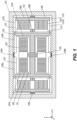
- Figure 1 depicts a first embodiment of a two-axis MEMS accelerometer according to the present invention.
- Figure 1 shows a top-down view of the accelerometer, such that the substrate upon which the accelerometer is formed lies parallel to the plane of the page, i.e. the X-Y plane.
- the substrate may be silicon or any other suitable material which can be patterned to form the MEMS structures of the accelerometer.
- the upper surface of the substrate defines a substrate plane, which may be generally flat and parallel to the plane of the page of Figure 1 .
- the substrate plane may intersect the MEMS structures described in more detail below, or may be located above or below the MEMS structures.
- the precise vertical position of the substrate plane is not important, only its orientation.
- the substrate plane is parallel to the X-Y plane, within which the X- and Y-axes discussed below lie.
- the X- and Y-axes may also be referred to as first and second axes.
- the accelerometer includes a proof mass 101 which extends around the exterior of the accelerometer components, i.e. the proof mass 101 encloses the remaining accelerometer components parallel to the substrate plane.
- the profile of the proof mass 101 parallel to the substrate plane is a regular, symmetrical shape with a hollow centre within which accelerometer components can be located.
- proof mass 101 is a rectangle.
- the proof mass has a thickness perpendicular to the substrate plane, i.e. in the Z axis.
- the thickness and the vertical position of the proof mass 101 are such that the centre of mass of the proof mass 101 in the Z axis is centred with respect to the spring structures (described in more detail below) which permit the proof mass 101 to move with respect to the substrate.
- movement of the MEMS accelerometer within the substrate plane does not cause rotation of the proof mass 101 out of parallel with the substrate plane.
- the proof mass 101 is permitted to move with respect to the substrate by a plurality of springs and intervening structures, by which the proof mass is suspended above the substrate.
- proof mass 101 is connected by springs 116a and 116b to moveable Y-axis measurement structure 112.
- Moveable Y-axis measurement structure 112 is floating, i.e. it is not directly anchored to the substrate and, as such, is capable of moving with respect to the substrate as permitted by the intervening structures between the moveable Y-axis measurement structure and one or more substrate anchor points.
- Springs 116a and 116b are shaped such that movement of the proof mass 101 along the Y-axis is strongly mechanically coupled to the moveable Y-axis measurement structure 112, while movement of the proof mass 101 along the X-axis is weakly mechanically coupled to or decoupled from the moveable Y-axis measurement structure 112.
- the precise shape and form of springs 116a and 116b is described in more detail below. Consequently, springs 116a and 116b permit the proof mass 101 to move along the X-axis relative to the moveable Y-axis measurement structure 112 while resisting movement of proof mass 101 along the Y-axis relative to the moveable Y-axis measurement structure 112.
- the proof mass 101 and moveable Y-axis measurement structure 112 are therefore said to be mechanically coupled in the Y-axis and mechanically decoupled in the X-axis.
- Moveable Y-axis measurement structure 112 is in turn connected by spring 117a and 117b to fixed support structure 115.
- Springs 117a and 117b are shaped such that movement of the moveable Y-axis measurement 112 structure along the X-axis is strongly mechanically coupled to the fixed support structure 115, while movement of the moveable Y-axis measurement structure 112 along the Y-axis is weakly mechanically coupled to or decoupled from the fixed support structure 115.
- the precise shape and form of springs 117a and 117b is described in more detail below.
- springs 117a and 117b permit moveable Y-axis measurement structure 112 to move along the Y-axis relative to the fixed support structure 115 while resisting movement of the moveable Y-axis measurement structure 112 along the X-axis relative to the fixed support structure 115.
- the moveable Y-axis measurement structure 112 and fixed support structure 115 are therefore said to be mechanically coupled in the X-axis and mechanically decoupled in the Y-axis.
- Fixed support structure 115 is connected to the substrate via anchor point(s) 120.
- the fixed support structure is fixed with respect to the substrate.
- the body and arms of the fixed support structure which extend away from the anchor point are sufficiently rigid that the body and arms of the fixed support structure move by such a small amount relative to the substrate that they too can be thought of as fixed. Consequently, the proof-mass is connected via springs 116a, 116b, moveable Y-axis measurement structure 112 and springs 117a, 117b to the fixed support structure 115 and the substrate.
- the proof mass 101 is decoupled from the fixed measurement structure 115 (and the substrate) in both the X- and Y-axes by springs 116a, 116b, moveable Y-axis measurement structure 112 and springs 117a, 117b.
- the accelerometer therefore includes two moveable Y-axis measurement structures 112 and two sets of springs 116a, 116b, 117a and 117b.
- the accelerometer may include a separate fixed support structure 115 to which the left-side springs 117a and 117b are connected, of the fixed support structure may be a unitary element which extends symmetrically across both sides of the accelerometer.
- proof mass 101 is connected by springs 126a and 126b to moveable X-axis measurement structure 122.
- Moveable X-axis measurement structure 122 is floating, i.e. it is not directly anchored to the substrate and, as such, is capable of moving with respect to the substrate as permitted by the intervening structures between the moveable X-axis measurement structure and one or more substrate anchor points.
- Springs 126a and 126b are shaped such that movement of the proof mass 101 along the X-axis is strongly mechanically coupled to the moveable X-axis measurement structure 122, while movement of the proof mass 101 along the Y-axis is weakly mechanically coupled to or decoupled from the moveable X-axis measurement structure 122.
- the precise shape and form of springs 126a and 126b is described in more detail below. Consequently, springs 126a and 126b permit the proof mass 101 to move along the Y-axis relative to the moveable X-axis measurement structure 122 while resisting movement of proof mass 101 along the X-axis relative to the moveable X-axis measurement structure 122.
- the proof mass 101 and moveable X-axis measurement structure 122 are therefore said to be mechanically coupled in the X-axis and mechanically decoupled in the Y-axis.
- Moveable X-axis measurement structure 122 is in turn connected by spring 127a and 127b to fixed support structure 115.
- Springs 127a and 127b are shaped such that movement of the moveable X-axis measurement 122 structure along the Y-axis is strongly mechanically coupled to the fixed support structure 115, while movement of the moveable X-axis measurement structure 122 along the X-axis is weakly mechanically coupled to or decoupled from the fixed support structure 115.
- the precise shape and form of springs 127a and 127b is described in more detail below.
- springs 127a and 127b permit moveable X-axis measurement structure 122 to move along the X-axis relative to the fixed support structure 115 while resisting movement of the moveable X-axis measurement structure 122 along the Y-axis relative to the fixed support structure 115.
- the moveable X-axis measurement structure 122 and fixed support structure 115 are therefore said to be mechanically coupled in the Y-axis and mechanically decoupled in the X-axis.
- fixed support structure 115 is connected to the substrate via anchor point(s) 120. As such, the fixed support structure is fixed with respect to the substrate. Consequently, the proof-mass is connected via springs 126a, 126b, moveable X-axis measurement structure 122 and springs 127a, 127b to the fixed support structure 115 and the substrate.
- the proof mass 101 is decoupled from the fixed measurement structure 115 (and the substrate) in both the X- and Y-axes by springs 126a, 126b, moveable X-axis measurement structure 122 and springs 127a, 127b.
- the accelerometer therefore includes two moveable X-axis measurement structures 122 and two sets of springs 126a, 126b, 127a and 127b.
- the accelerometer may include a separate fixed support structure 115 to which the lower-half springs 127a and 127b are connected, of the fixed support structure may be a unitary element which extends symmetrically across both upper and lower halves of the accelerometer (as well as across both left and right sides).
- Springs 116a, 116b, 117a, 117b, 126a, 126b, 127a and 127b are also shaped to minimise deflection of the springs in Z-axis, i.e. to prevent movement of the moveable X-axis measurement structure 122 and the proof mass 101 in the Z-axis.
- springs 116a, 116b, 117a, 117b, 126a, 126b, 127a and 127b are beam-shaped, with a rectangular cross-section (taken perpendicular to the longitudinal axis of the beam) having a smaller width (in the X- or Y-axis) than height (in the Z-axis).
- folded springs may be used, which make the spring softer in same proportion with the number of springs in series.
- the width of the spring array dictates the softness in the cross-axis direction.
- box springs may be used Box strings are stiffer in the cross-axis direction than folded springs, but are also stiffer in the measuring axis.
- the length of the springs is set to control the spring constant, i.e. to control the mechanical sensitivity of the accelerometer to acceleration, in combination with all the other springs in series decoupling the mass from the anchor.
- the width of the beam in the Y-direction is narrower such that the beam-shaped spring is easily deformed in the Y-direction, while the height of the beam in the Z-direction resists deformation of the springs in the Z-direction.
- the springs are is beam-shaped, i.e. forms a generally straight line in the X-direction, the springs 117a, 117b, 126a and 126 resist deformation in the X-direction.
- the width of the beam in the X-direction is narrower such that the beam-shaped spring is easily deformed in the X-direction, while the height of the beam in the Z-direction resists deformation of the springs in the Z-direction.
- the springs are is beam-shaped, i.e. forms a generally straight line in the Y-direction, the springs 116a, 116b, 127a and 127b resist deformation in the Y-direction.
- any suitable shape can be used as long as the spring exhibits the properties of stiffness in one of the X- or Y-directions and the Z-direction along with relative looseness in the other of the X- or Y-directions.
- the accelerometer also includes fixed Y-axis measurement structures 111 and fixed X-axis measurement structures 121.
- Fixed X-axis measurement structures 121 are preferably anchored to the substrate at anchor point(s) 120, along with the fixed support structure 115.
- a common central anchor point prevents thermal (or other) deformation of the substrate from changing the relative positions of the fixed support structure and the fixed X-axis measurement structures 121.
- Fixed Y-axis measurement structures 111 are fixed to the substrate via anchor point(s) 110, which are separated from the anchor point(s) 120 along the X-axis, but still located on the central X-axis of the accelerometer.
- Comb electrodes extend from the fixed Y-axis measurement structures 111 are and from the moveable Y-axis measurement structures.
- comb electrodes extend from fixed X-axis measurement structures 121 and from moveable X-axis measurement structures 122.
- the comb electrodes define a plurality of fingers which extend away from the fixed and moveable measurement structures, such that the fingers of comb electrodes which extend away from the fixed X- and Y- axis measurement structures extend towards the moveable X- and Y-axis measurement structures respectively.
- the fingers of comb electrodes which extend away from the moveable X- and Y- axis measurement structures extend towards the fixed X- and Y-axis measurement structures respectively.
- the fingers of opposing comb electrodes are interspersed and not in direct electrical contact.
- the comb electrodes form comb sense capacitors, which are used to measure movement of the moveable X-axis measurement structures 122 relative to the fixed X-axis measurement structures 121 and to measure movement of the moveable Y-axis measurement structures 112 relative to the fixed Y-axis measurement structures.
- the comb fingers which extend from the fixed and moveable Y-axis measurement structures define two comb sense capacitors 113 and 114.
- Capacitor 113 is formed from the comb fingers extending from the fixed and moveable Y-axis measurement structures in the upper half of the accelerometer as shown in Figure 1 .
- Capacitor 114 is formed from the comb fingers extending from the fixed and moveable Y-axis measurement structures in the lower half of the accelerometer as shown in Figure 1 .
- the arrangement of comb fingers in capacitor 113 is opposite to the arrangement of comb fingers in capacitor 114. As such, when the accelerometer undergoes acceleration in the Y-direction, if the comb fingers of capacitor 113 move closer together, the comb teeth of capacitor 114 move further apart and vice versa.
- Capacitor 123 is formed from the comb fingers extending from the fixed and moveable X-axis measurement structures in the left half of the accelerometer as shown in Figure 1 .
- Capacitor 124 is formed from the comb fingers extending from the fixed and moveable X-axis measurement structures in the right half of the accelerometer as shown in Figure 1 .
- the arrangement of comb fingers in capacitor 123 is opposite to the arrangement of comb fingers in capacitor 124. As such, when the accelerometer undergoes acceleration in the X-direction, if the comb fingers of capacitor 123 move closer together, the comb teeth of capacitor 124 move further apart and vice versa.
- the moveable X- and Y-axis measurement structures also move relative to the substrate - and relative to the fixed X- and Y-axis measurement structures - thereby changing the capacitance of the sense comb capacitors in response to the movement.
- each comb sense capacitor is perpendicular to the longitudinal axis of the capacitor's comb fingers.
- capacitance of the comb sense capacitors changes with both relative movement of the comb fingers along the sense axis and relative movement of the comb fingers perpendicular to the sense axis.
- prior art accelerometers use a single proof mass for multiple sense axes introduced cross-axis error, where movement of the proof mass and moveable measurement structures out of the sense axis of a given sense capacitor produces and error due to the parasitic change in capacitance caused by movement of the sense axis combs away from each other perpendicular to the sense axis.
- the accelerometer of Figure 1 solves this problem in two ways: by mechanically decoupling the movement measurement structures from movement of the proof mass 101 perpendicular to the sense axis, and by using four sense comb capacitors for each sense axis that are reflected about both the X and Y sense axes.
- any movement of the proof mass 101 in the X-direction is strongly mechanically coupled to the moveable X-axis measurement structures 122 by spring 126a and 126b, while movement of the proof mass 101 in the Y-direction is weakly coupled to or decoupled from the moveable X-axis measurement structures 122.
- movement of the proof mass 101 in the X-direction causes a corresponding movement of the moveable X-axis measurement structures 122
- movement of the proof mass in the Y-direction causes no or very little movement of the moveable X-axis measurement structures 122 in the Y-direction, and thus no or very little change of capacitance in the X-axis sense capacitor due the acceleration in the Y-direction.
- any movement of the proof mass 101 in the Y-direction is strongly mechanically coupled to the moveable Y-axis measurement structures 112 by spring 116a and 116b, while movement of the proof mass 101 in the X-direction is weakly coupled to or decoupled from the moveable Y-axis measurement structures 112. That is, movement of the proof mass 101 in the Y-direction causes a corresponding movement of the moveable Y-axis measurement structures 112, while movement of the proof mass in the X-direction causes no or very little movement of the moveable Y-axis measurement structures 122 in the X-direction, and thus no or very little change of capacitance in the Y-axis sense capacitor due the acceleration in the X-direction.
- any remaining movement of the moveable X-axis measurement structures 122 in the Y-direction is cancelled out, since as the comb fingers of the upper-half X-axis sense capacitor move closer together, the comb fingers of the lower-half X-axis sense capacitor move further apart by an equal amount, and vice versa.
- the accelerometer of Figure 1 also, optionally, includes stoppers 130a-d, which may be anchored to the substrate. Stoppers 130a-d are positioned adjacent to the moveable X-axis measurement structures 122 and moveable Y-axis measurement structures 112. Stoppers 130a-d restrict movement of the moveable X- and Y-axis measurement structures in at least one direction perpendicular to the sense axis parallel to the substrate plane. Stoppers 130a-d are depicted located between the moveable X- and Y-axis measurement structures 122, 112 and the proof mass 101.
- Stoppers 130a-d therefore restrict movement of the moveable X- and Y-axis measurement structures in directions perpendicular to the sense axis and towards the exterior of the accelerometer. Additional stoppers may also be included which restrict movement of the moveable X- and Y-axis measurement structures in directions perpendicular to the sense axis and towards the interior of the accelerometer, e.g. located adjacent to the moveable X- and Y-axis measurement structures, between the moveable X- and Y-axis measurement structures and the fixed X- and Y-axis measurement structures or the fixed support structure(s) 115.
- the device may include relative stoppers which extend from a proof mass or other structure to prevent relative movement of the proof mass/structure and adjacent structures.
- stoppers may be positioned outside the proof mass 101 and anchored to the substrate.
- stoppers may be attached to the cap wafer of the device in addition to or instead of being attached to the substrate.
- Figure 2 depicts a second embodiment of a two-axis MEMS accelerometer according to the present invention.
- the accelerometer of Figure 2 includes a proof mass 201 which extends around the exterior of the accelerometer components, i.e. the proof mass 201 encloses the remaining accelerometer components parallel to the substrate plane.
- the profile of the proof mass 201 parallel to the substrate plane is a regular, symmetrical shape with a hollow centre within which accelerometer components can be located.
- proof mass 201 is a rectangle.
- the proof mass has a thickness perpendicular to the substrate plane, i.e. in the Z axis.
- the thickness and the vertical position of the proof mass 201 are such that the centre of mass of the proof mass 201 in the Z axis is centred with respect to the spring structures (described in more detail below) which permit the proof mass 201 to move with respect to the substrate. As such, movement of the MEMS accelerometer within the substrate plane does not cause rotation of the proof mass 201 out of parallel with the substrate plane.
- the proof mass 201 is permitted to move with respect to the substrate by a plurality of springs and intervening structure, by which the proof mass is suspended above the substrate.
- proof mass 201 is connected by springs 216a and 216b to moveable Y-axis measurement structure 212.
- Moveable Y-axis measurement structure 212 is floating, i.e. it is not directly anchored to the substrate and, as such, is capable of moving with respect to the substrate as permitted by the intervening structures between the moveable Y-axis measurement structure 212 and one or more substrate anchor points.
- Springs 216a and 216b are shaped such that movement of the proof mass 201 along the Y-axis is strongly mechanically coupled to the moveable Y-axis measurement structure 212, while movement of the proof mass 201 along the X-axis is weakly mechanically coupled to or decoupled from the moveable Y-axis measurement structure 212.
- the precise shape and form of springs 216a and 216b is the same as described above with respect to the springs 116a, 116b, 117a, 117b, 126a, 1276b, 127a and 127b of Figure 1 .
- springs 216a and 216b permit the proof mass 201 to move along the X-axis relative to the moveable Y-axis measurement structure 212 while resisting movement of proof mass 201 along the Y-axis relative to the moveable Y-axis measurement structure 212.
- the proof mass 201 and moveable Y-axis measurement structure 212 are therefore said to be mechanically coupled in the Y-axis and mechanically decoupled in the X-axis.
- Moveable Y-axis measurement structure 212 is in turn connected by spring 217a and 217b to fixed support structure 215.
- Springs 217a and 217b are shaped such that movement of the moveable Y-axis measurement 212 structure along the X-axis is strongly mechanically coupled to the fixed support structure 215, while movement of the moveable Y-axis measurement structure 212 along the Y-axis is weakly mechanically coupled to or decoupled from the fixed support structure 215.
- the precise shape and form of springs 217a and 217b is the same as described above with respect to the springs 116a, 116b, 117a, 117b, 126a, 1276b, 127a and 127b of Figure 1 .
- springs 217a and 217b permit moveable Y-axis measurement structure 212 to move along the Y-axis relative to the fixed support structure 215 while resisting movement of the moveable Y-axis measurement structure 212 along the X-axis relative to the fixed support structure 215.
- the moveable Y-axis measurement structure 212 and fixed support structure 215 are therefore said to be mechanically coupled in the X-axis and mechanically decoupled in the Y-axis.
- Fixed support structure 215 is connected to the substrate via anchor point(s) 220.
- the fixed support structure is fixed with respect to the substrate.
- the body and arms of the fixed support structure 215 which extend away from the anchor point 220 are sufficiently rigid that the body and arms of the fixed support structure move by such a small amount relative to the substrate that they too can be thought of as fixed. Consequently, the proof-mass is connected via springs 216a, 216b, moveable Y-axis measurement structure 212 and springs 217a, 217b to the fixed support structure 215 and the substrate.
- the proof mass 201 is decoupled from the fixed measurement structure 215 (and the substrate) in both the X- and Y-axes by springs 216a, 216b, moveable Y-axis measurement structure 212 and springs 217a, 217b.
- the accelerometer therefore includes two moveable Y-axis measurement structures 212 and two sets of springs 216a, 216b, 217a and 217b.
- the accelerometer of Figure 2 includes a separate fixed support structure 215 to which the left-side springs 217a and 217b are connected, and there is a gap at the centre of the accelerometer between two sets of anchor points 220 to which the two fixed support structures 215 are fixed.
- the accelerometer of Figure 2 includes a single, unitary moveable X-axis measurement structure 222, shaped like the letter "H" rotated by 90 degrees.
- the centre bar of the H-shaped moveable X-axis measurement structure 222 extends through the gap between anchor points 220 at the centre of the accelerometer, such that each of the side bar of the H-shaped moveable X-axis measurement structure 222 are located on opposite sides of the anchor points 220, i.e. one "above” the anchor points 220, as seen on the page, and one "below” the anchor points 220, as seen on the page.
- proof mass 201 is connected by springs 226a and 226b to moveable X-axis measurement structure 222.
- Moveable X-axis measurement structure 222 is floating, i.e. it is not directly anchored to the substrate and, as such, is capable of moving with respect to the substrate as permitted by the intervening structures between the moveable X-axis measurement structure 222 and one or more substrate anchor points.
- Springs 226a and 226b are shaped such that movement of the proof mass 201 along the X-axis is strongly mechanically coupled to the moveable X-axis measurement structure 222, while movement of the proof mass 201 along the Y-axis is weakly mechanically coupled to or decoupled from the moveable X-axis measurement structure 222.
- the precise shape and form of springs 226a and 226b is the same as described above for the springs of Figure 1 and for springs 216a, 216b, 217a and 217b.
- springs 226a and 226b permit the proof mass 201 to move along the Y-axis relative to the moveable X-axis measurement structure 222 while resisting movement of proof mass 201 along the X-axis relative to the moveable X-axis measurement structure 222.
- the proof mass 201 and moveable X-axis measurement structure 222 are therefore said to be mechanically coupled in the X-axis and mechanically decoupled in the Y-axis.
- Moveable X-axis measurement structure 222 is in turn connected by springs 227a and 227b to fixed support structures 215.
- spring 227a connects the moveable X-axis measurement structure 222 to the left-hand side fixed support structure
- spring 227b connected the moveable X-axis measurement structure 222 to the right-hand side fixed support structure 215.
- Springs 227a and 227b are shaped such that movement of the moveable X-axis measurement 222 structure along the Y-axis is strongly mechanically coupled to the fixed support structures 215, while movement of the moveable X-axis measurement structure 222 along the X-axis is weakly mechanically coupled to or decoupled from the fixed support structures 2115.
- springs 227a and 227b permit moveable X-axis measurement structure 222 to move along the X-axis relative to the fixed support structures 215 while resisting movement of the moveable X-axis measurement structure 222 along the Y-axis relative to the fixed support structures 215.
- the moveable X-axis measurement structure 222 and fixed support structures 215 are therefore said to be mechanically coupled in the Y-axis and mechanically decoupled in the X-axis.
- fixed support structures 215 are connected to the substrate via anchor points 220. As such, the fixed support structures are fixed with respect to the substrate. Consequently, the proof mass 201 is connected via springs 226a, 226b, moveable X-axis measurement structure 222 and springs 227a, 227b to the fixed support structures 215 and the substrate.
- the proof mass 201 is decoupled from the fixed measurement structures 215 (and the substrate) in both the X- and Y-axes by springs 226a, 226b, moveable X-axis measurement structure 222 and springs 227a, 227b.
- the accelerometer therefore includes a second set of springs 226a, 226b, 227a and 227b which are connected to the H-shaped moveable X-axis measurement structure 222 and the fixed support structures 215.
- the width of the beam in the Y-direction is narrower such that the beam-shaped spring is easily deformed in the Y-direction, while the height of the beam in the Z-direction resists deformation of the springs in the Z-direction. Furthermore, since the springs are is beam-shaped, i.e. forms a generally straight line in the X-direction, the springs 217a, 217b, 226a and 226 resist deformation in the X-direction.
- the width of the beam in the X-direction is narrower such that the beam-shaped spring is easily deformed in the X-direction, while the height of the beam in the Z-direction resists deformation of the springs in the Z-direction.
- the springs are is beam-shaped, i.e. forms a generally straight line in the Y-direction, the springs 216a, 216b, 227a and 227b resist deformation in the Y-direction.
- any suitable shape can be used as long as the spring exhibits the properties of stiffness in one of the X- or Y-directions and the Z-direction along with relative looseness in the other of the X- or Y-directions.
- the accelerometer of Figure 2 also includes fixed Y-axis measurement structures 211 and fixed X-axis measurement structures 221.
- Fixed X-axis measurement structures 221 are preferably anchored to the substrate at anchor points 220, along with the fixed support structures 215.
- the accelerometer of Figure 2 includes four fixed X-axis measurement structures 221.
- the four fixed X-axis measurement structures 221 can be divided into two pairs, each pair being located on opposite sides of the central bar of the H-shaped moveable X-axis measurement structure. Within each pair of fixed X-axis measurement structures 221, the fixed X-axis measurement structures 221 are located on opposite sides of the fixed support structure 215.
- Fixed Y-axis measurement structures 211 are fixed to the substrate via anchor points 210, which are separated from the anchor points 220 along the X-axis, but still located on the central X-axis of the accelerometer.
- Comb electrodes extend from the fixed Y-axis measurement structures 211 and from the moveable Y-axis measurement structures 212. Similarly, comb electrodes extend from fixed X-axis measurement structures 221 and from the moveable X-axis measurement structure 222
- the comb electrodes form comb sense capacitors 213, 214, 223 and 224, in the same manner as described above for sense capacitors 113, 114, 123 and 124 with respect to Figure 1 .
- the moveable X- and Y-axis measurement structures also move relative to the substrate - and relative to the fixed X- and Y-axis measurement structures - thereby changing the capacitance of the sense comb capacitors in response to the movement.
- the present invention solves the problem reducing errors due to parasitic capacitance, i.e. of cross-axis error, which is described above with respect to Figure 1 , and of parasitic capacitance caused by rotation of the proof mass and measurement structures, in three ways: by mechanically decoupling the movement measurement structures from movement of the proof mass 201 perpendicular to the sense axis, by using two sense comb capacitors for each sense axis that are reflected about the sense axis, and by producing a different natural frequency of oscillation of the structure (i.e. the proof mass 201 and moveable measurement structures 212, 222) in the X and Y directions compared to the natural frequency of rotation of the structure about the Z-axis.
- any movement of the proof mass 201 in the X-direction is strongly mechanically coupled to the moveable X-axis measurement structure 222 by four springs 226a, 226b, and movement of the proof mass 201 in the Y-direction is weakly coupled to or decoupled from the moveable X-axis measurement structure 222.
- movement of the proof mass 101 in the X-direction causes a corresponding movement of the moveable X-axis measurement structure 222
- movement of the proof mass 201 in the Y-direction causes no or very little movement of the moveable X-axis measurement structures 222 in the Y-direction, and thus no or very little change of capacitance in the X-axis sense capacitor due the acceleration in the Y-direction.
- any movement of the proof mass 201 in the Y-direction is strongly mechanically coupled to the moveable Y-axis measurement structures 212 by springs 116a and 116b, while movement of the proof mass 201 in the X-direction is weakly coupled to or decoupled from the moveable Y-axis measurement structures 212.
- movement of the proof mass 201 in the Y-direction causes a corresponding movement of the moveable Y-axis measurement structures 212
- movement of the proof mass in the X-direction causes no or very little movement of the moveable Y-axis measurement structures 222 in the X-direction, and thus no or very little change of capacitance in the Y-axis sense capacitor due the acceleration in the X-direction.
- any remaining movement of the moveable X-axis measurement structure 222 in the Y-direction is cancelled out, since as the comb fingers of the upper-half X-axis sense capacitors move closer together, the comb fingers of the lower-half X-axis sense capacitors move further apart by an equal amount, and vice versa.
- the arrangement of sense capacitors 213, 214, 223 and 224 enables the use of double differential measurements, which cancels out errors causes due to manufacturing imperfections and misalignment.
- the natural frequency of rotation of the structure i.e. proof mass 201 and moveable measurement structures 212, 222
- the natural frequency of rotation of the structure is significantly higher than the natural frequency of oscillation of the proof mass 201 and moveable measurement structures 212, 222 in the X- and Y-axes.
- the accelerometer of Figure 2 may also include stoppers 230a-d, which are anchored to the substrate. Stoppers 230a-d are positioned adjacent to the moveable X-axis measurement structure 222 and moveable Y-axis measurement structures 212. Stoppers 230b and 230d restrict movement of the moveable X-axis measurement structure 222 in both directions along the Y axis. Stoppers 230a and 230c restrict movement of each moveable Y-axis measurement structure in at least one direction perpendicular along the Y-axis. Stoppers 230a-d are depicted located between the moveable X- and Y-axis measurement structures 222, 212 and the proof mass 201.
- Additional stoppers may also be included which restrict movement of the moveable Y-axis measurement structures 212 in directions perpendicular to the sense axis and towards the interior of the accelerometer, e.g. located adjacent to the moveable Y-axis measurement structures 212, between the moveable Y-axis measurement structures 212 and the fixed Y-axis measurement structures 211 or the fixed support structures 215.
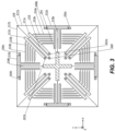
- Figure 3 depicts a third embodiment of a two-axis MEMS accelerometer according to the present invention.
- Figure 3 shows a top-down view of the accelerometer, such that the substrate upon which the accelerometer is formed lies parallel to the plane of the page, i.e. the X-Y plane.
- the substrate may be silicon or any other suitable material which can be patterned to form the MEMS structures of the accelerometer.
- the upper surface of the substrate defines a substrate plane, which may be generally flat and parallel to the plane of the page of Figure 3 .
- the substrate plane may intersect the MEMS structures described in more detail below, or may be located above or below the MEMS structures. The precise vertical position of the substrate plane is not important, only its orientation.
- the accelerometer includes a proof mass 301 which is located centrally within the accelerometer.
- the proof mass is depicted as a cross shape in Figure 3 , although any shape which allows the proof mass to move within the required range within the centre of the device without colliding with other components may be used.
- the proof mass 301 is permitted to move within the accelerometer, relative to the substrate, by a plurality of springs and intervening structures, by which the proof mass is suspended above the substrate.
- the proof mass 301 is connected by spring 316a to a moveable X-axis measurement structure 312a and by spring 316b to a moveable Y-axis measurement structure 312b.
- Springs 316a and 316b extend away from the proof mass at a 90-degree angle to one another and have the same length.
- Moveable X-axis measurement structure 312a and moveable Y-axis measurement structure 312b have the same shape, but moveable Y-axis measurement structure 312b is a 90-degree counter-clockwise rotation of moveable X-axis measurement structure 312a.
- a spring 317a extends at an angle of 90 degrees from the spring 316a and towards a corner of the device.
- a spring 317b extends at an angle of 90 degrees from the spring 316b towards the same corner of the device as spring 317a.
- Springs 317a and 317b meet and are joined at the corner of the device.
- Springs 316a, 316b, 317a and 317b therefore lie on the edges of a quadrilateral.
- Another spring 318 extends toward the centre of the device, where it is joined to a fixed support structure 315, which is anchored to the substrate at anchor point 320.
- Fixed structure 315 extends from the anchor point 320 towards the corner of the device where springs 317a and 317b meet.
- springs 316a and 316b and moveable X- and Y-axis measurement structures which form the edges of the repeated structure, are not necessarily duplicated. Instead, spring 316a of one corner also performs the function of spring 316b of the adjacent corner and so on.
- the proof mass is suspended from the anchor points 320 via springs 318, 317a and 317b, moveable X- and Y-axis measurements structures 312a and 312, and springs 316a and 316b.
- the springs are shaped, as described above with respect to Figures 1 and 2 , as beams, such that the springs easily deform perpendicular to their longitudinal axes and parallel to the X-Y plane, while resisting deformation in the Z-direction and resisting deformation along their longitudinal axes.
- the proof mass is free to move parallel to the X-Y plane, within the bounds set by the easy transverse deformation of the springs.
- the moveable X-axis measurement structures are only mechanically coupled to X-axis movement of the proof mass 301 by springs 316a. Movement of the proof mass 301 along the X-axis is mechanically coupled to moveable X-axis measurement structure 312a due to the resistance to deformation of the springs 316a along their longitudinal axes, which extend in the X-direction. However, movement of the proof mass 301 along the Y-axis is weakly coupled to or mechanically decoupled from the moveable X-axis measurement structures 312a due to the easy deformation of springs 316a in the Y-direction.
- the moveable Y-axis measurement structures are only mechanically coupled to Y-axis movement of the proof mass 301 by springs 316b. Movement of the proof mass 301 along the Y-axis is mechanically coupled to moveable Y-axis measurement structure 312b due to the resistance to deformation of the springs 316b along their longitudinal axes, which extend in the Y-direction. However, movement of the proof mass 301 along the X-axis is weakly coupled to or mechanically decoupled from the moveable Y-axis measurement structures 312b due to the easy deformation of springs 316b in the X-direction.
- the accelerometer also includes fixed X-axis measurement structures 311a and fixed Y-axis measurement structures 311b.
- Fixed X-axis measurement structure 311a is preferably anchored to the substrate at anchor point 321a.
- the fixed X-axis measurement structure 311a extends diagonally, parallel to the fixed support structure 315, from the anchor point towards the exterior of the device.
- Fixed Y-axis measurement structure 311b is preferably anchored to the substrate at anchor points 321b.
- the fixed Y-axis measurement structure 311b extends diagonally, parallel to the fixed support structure 315 and fixed X-axis measurement structure 311a, from the anchor point towards the exterior of the device.
- comb electrodes 313a Extending in the Y-direction from the fixed X-axis measurement structure 311a are comb electrodes 313a (i.e. at a 45-degree angle to the fixed X-axis measurement structure 311a), and in the Y-direction from the moveable X-axis measurement structure 312a comb electrodes 314a extend (at a 90 degree angle from the moveable Y-axis measurement structure).
- comb electrodes 313b extend in the X-direction (at a 45-degree angle from the fixed Y-axis measurement structure 311b)
- moveable Y-axis measurement structure 312b comb electrodes 114b extend in the X-direction (at a 90-degree angle from the moveable Y-axis measurement structure 312b).
- the comb electrodes 113a, 113b, 114a and 114b define a plurality of fingers which extend away from the fixed and moveable measurement structures, such that the fingers of comb electrodes 113a and 113b extend away from the fixed X- and Y- axis measurement structures towards the moveable X- and Y-axis measurement structures respectively.
- the fingers of comb electrodes 114a and 114b extend away from the moveable X- and Y- axis measurement structures towards the fixed X- and Y-axis measurement structures respectively.
- the fingers of opposing comb electrodes are interspersed and not in direct electrical contact.
- the comb electrodes form comb sense capacitors, which are used to measure movement of the moveable X-axis measurement structures 312a relative to the fixed X-axis measurement structures 311a and to measure movement of the moveable Y-axis measurement structures 312b relative to the fixed Y-axis measurement structures.
- each comb sense capacitor is perpendicular to the longitudinal axis of the capacitor's comb fingers.
- capacitance of the comb sense capacitors changes with both relative movement of the comb fingers along the sense axis and relative movement of the comb fingers perpendicular to the sense axis.
- prior art accelerometers use a single proof mass for multiple sense axes introduced cross-axis error, where movement of the proof mass and moveable measurement structures out of the sense axis of a given sense capacitor produces and error due to the parasitic change in capacitance caused by movement of the sense axis combs away from each other perpendicular to the sense axis.
- the accelerometer of Figure 3 solves this problem in two ways: by mechanically decoupling the movement measurement structures from movement of the proof mass 301 perpendicular to the sense axis, and by using two sense comb capacitors for each sense axis that are reflected about the sense axis.
- any movement of the proof mass 301 in the X-direction is strongly mechanically coupled to the moveable X-axis measurement structures 312a by spring 316a, while movement of the proof mass 301 in the Y-direction is weakly coupled to or decoupled from the moveable X-axis measurement structures 312a.
- movement of the proof mass 301 in the X-direction causes a corresponding movement of the moveable X-axis measurement structures 312a
- movement of the proof mass in the Y-direction causes no or very little movement of the moveable X-axis measurement structures 312a in the Y-direction, and thus no or very little change of capacitance in the X-axis sense capacitor due the acceleration in the Y-direction.
- any movement of the proof mass 301 in the Y-direction is strongly mechanically coupled to the moveable Y-axis measurement structures 312b by spring 316b, while movement of the proof mass 301 in the X-direction is weakly coupled to or decoupled from the moveable Y-axis measurement structures 312b. That is, movement of the proof mass 301 in the Y-direction causes a corresponding movement of the moveable Y-axis measurement structures 312b, while movement of the proof mass in the X-direction causes no or very little movement of the moveable Y-axis measurement structures 312b in the X-direction, and thus no or very little change of capacitance in the Y-axis sense capacitor due the acceleration in the X-direction.
- any remaining movement of the moveable X-axis measurement structures 312a in the Y-direction is cancelled out, since as the comb fingers of the upper-half X-axis sense capacitor move closer together, the comb fingers of the lower-half X-axis sense capacitor move further apart by an equal amount, and vice versa.
- the accelerometer of Figure 1 also, optionally, includes stoppers 330a-d, which are anchored to the substrate. Stoppers 330a-d are positioned adjacent to the moveable X-axis measurement structures 312a and moveable Y-axis measurement structures 312b. Stoppers 330a-d restrict movement of the moveable X- and Y-axis measurement structures perpendicular to the sense axis. Pairs of stoppers 330a-d are located adjacent to each moveable X- and Y-axis measurement structure 312a, 312b, with one stopper on each side of the measurement structure. Stoppers 330a-d therefore restrict movement of the moveable X- and Y-axis measurement structures 312a, 312b in directions perpendicular to the sense axes of the sense capacitors.
- Figure 4 depicts a three-axis MEMS accelerometer according to the present invention.
- Figure 4 depicts the two-axis accelerometer of Figure 2 401 surrounded by two Z-axis proof masses 410a and 410b.
- Accelerometer 401 may alternatively be the accelerometer of Figure 1 .
- the two-axis accelerometer structure 401 and the masses 410a, 410b (when at rest) generally lie in the same plane parallel to the substrate plane.
- the proof masses 410a, 410b are see-saw proof masses and are rotatably coupled to the proof mass of the two-axis accelerometer 401 such that the see-saw proof masses 410a and 410b can rotate about rotation axes RAa and RAb out of parallel to the substrate plane.
- the see-saw proof masses 410a and 410b are connected to the proof mass 401 of the two-axis accelerometer, the proof masses 410a and 410b are also free to move parallel to the substrate plane relative to the substrate.
- the entire mass of both see-saw proof masses 410a, 410b also acts as a proof mass for the two-axis accelerometer.
- the proof mass 401 of the two-axis accelerometer may be reduced in size compared to the embodiments of Figures 1 and 2 .
- the combined proof mass of see-saw proof masses 410a, 410b and proof mass 401 is used for measurement of acceleration parallel to the substrate plane, i.e. in the X and Y directions, the X- and Y-acceleration measurements are much less susceptible to noise caused by unwanted vibration of the proof mass, e.g. thermal noise.
- the see-saw proof masses 410a, 410b are connected to the two-axis accelerometer proof mass 401 via torsion springs 411a-d, which allow rotation of the see-saw proof masses 410a, 410b out of the substrate plane about rotation axes RAa, RAb.
- the see-saw proof masses 410a, 410b are roughly C- or U-shaped and are arranged such that see-saw proof mass 410b is a mirror image of see-saw proof mass 410a and so that together the proof masses 410a, 41 0b extend around the outside of and enclose the two axis accelerometer 401.
- the see-saw proof masses 410a, 410b are equally sized, and the torsion springs (and therefore rotation axes RAa and RAb) are located symmetrically about the central Y-axis of the two-axis accelerometer 401.
- the torsion springs 411a-d are positioned parallel to the substrate plane, at the same height above the substrate plane as the centre of mass of the two-axis accelerometer 401. At rest, the centres of mass of the see-saw proof masses 410a and 410b are also located at the same height above the substrate plane as the torsion springs 411a-d and the centre of mass of the two-axis accelerometer 401.
- the centre of mass of see-saw proof mass 410a is offset from its rotation axis RAa
- the centre of mass of see-saw proof mass 410b is equally offset from its rotation axis RAb parallel to the substrate plane, in the opposite direction to the offset of proof mass 410a from rotation axis RAa.
- the see-saw proof masses 410a, 410b therefore rotate out of parallel with the substrate plane, and this movement can be measurement to determine the Z-axis acceleration.
- the see-saw proof masses 410a, 410b can be thought of as each defining an asymmetric mass and a symmetric mass.
- the symmetric mass is the double the mass of the smaller side of the see-saw proof mass 410a, 410b (i.e. the mass of the smaller side plus an equal mass from the large side which balances the smaller side).
- the asymmetric mass is the remaining mass of the see-saw proof mass 410a, 410b, i.e. the part of the proof mass that is acted upon by the external acceleration in the Z direction, (i.e. the acceleration applied to the accelerometer package which is to be measured) which causes rotation of the see-saw proof masses 410a, 410b about the rotation axes RAa, RAb.
- the combined centre of mass of both see-saw proof masses 410a, 410b is located at the centre of the accelerometer, along with the centre of mass of the in-plane structure 401, even when the see-saw proof mass rotate out of parallel with the substrate plane, since the change in position of the centre of mass of proof mass 410a caused by rotation of the proof mass is offset by an equal and opposite change in the position of the centre of mass 410b caused by its rotation.
- the see-saw proof masses 410a, 410b are coupled together by springs 412a and 412b, which are located at the adjacent ends of the see-saw proof masses 41 0a, 410b.
- Springs 412a and 412b permit relative movement of the ends of the see-saw proof masses 410a and 410b away from each other parallel to the substrate plane, but resist relative movement of the ends of the see-saw proof masses 410a, 410b away from each other perpendicular to the substrate plane, i.e. in the Z direction.
- the see-saw proof masses 410a, 410b are generally free to rotate about rotation axes RAa and RAb in opposite directions, i.e.
- see-saw proof mass 410a rotates clockwise and see-saw proof mass 410b rotates anti-clockwise, or vice versa, since this causes relative motion of the ends of the see-saw proof masses 410a, 410b away or towards each other parallel to the substrate plane.
- rotation of the see-saw proof masses 410a, 410b in the same direction i.e. both clockwise, or both anti-clockwise
- the springs 412a, 412b since such rotation causes relative motion of the ends of the see-saw proof masses 410a, 410b perpendicular to the substrate plane.
- This coupling prevents the see-saw proof masses 410a, 410b from moving in response to external angular acceleration, in which case the see-saw proof masses 410a, 410b would rotate in the same direction, while still allowing the see-saw proof masses 410a, 410b to move in response to linear acceleration perpendicular to the substrate plane, which causes the see-saw proof masses 410a, 410b to rotate in opposite directions.
- Movement of the see-saw proof masses 410a, 410b is measured capacitively.
- Rotation of the see-saw proof masses 410a, 410b is preferably measured by gap detection capacitors with parallel-plate electrodes located above or below the see-saw proof masses 410a, 410b, or can be measured by comb capacitors with moveable electrodes located on the see-saw proof masses 410a, 410b and stationary electrodes located on the two axis accelerometer proof mass 401.
- electrodes 430a-d are formed on the see-saw proof masses 410a, 410b, and counterpart electrodes are formed on the substrate and/or cap wafer (not shown) above or below the see-saw proof masses 410a, 41 0b.
- the electrodes 430a and 430b are located at the ends of the C-shape of the see-saw proof mass 410a.
- the electrodes 430c and 430d are located at the ends of the C-shape of the see-saw proof mass 410b.
- the gaps between the electrodes 430a-d and the counterpart electrodes on the substrate and/or cap wafer increase or decrease depending on the extent of the rotation, thereby changing the measured capacitance of the gap-detection capacitors, which can in turn be used to derive the Z-axis acceleration of the device.
- the see-saw proof masses 410a and 410b may comprises further electrodes 431a-d.
- Electrode 431a is located on the same side of the C-shape of proof mass 410a as electrode 430a, on the opposite side of rotation axis RAa and torsion spring 411a to electrode 430a.
- electrode 431b is located on the same side of the C-shape of proof mass 410a as electrode 430b, on the opposite side of rotation axis RAa and torsion spring 411b to electrode 430b.
- Electrode 431c is located on the same side of the C-shape of proof mass 410b as electrode 430c, on the opposite side of rotation axis RAb and torsion spring 411c to electrode 430c.
- electrode 431d is located on the same side of the C-shape of proof mass 410b as electrode 430d, on the opposite side of rotation axis RAb and torsion spring 411d to electrode 430d.
- electrodes 430a-d counterpart electrodes to electrodes 431a-d are formed on the substrate and/or cap wafer (not shown) above or below the see-saw proof masses 410a, 41 0b.
- the see-saw proof masses 410a, 410b are connected to the proof mass of the two-axis accelerometer 401, the proof masses 410a, 41 0b are, like the proof mass 401, free to move parallel to the substrate plane relative to the substrate.
- the capacitors formed from electrodes 430a-d and 431a-d are used to measure movement of the see-saw proof masses 410a, 410b out of parallel to the substrate plane (i.e.
- alignment of the electrodes 430a-d, 431a-d and the corresponding electrodes above/below the see-saw proof masses 410a, 410b may not be perfectly parallel, e.g. due to imperfect alignment of the cap wafer during manufacturing or stress on the device during operation. Under such conditions, movement of the proof masses 410a, 410b parallel to the substrate plane may cause changes in the individual capacitances measured by each of the individual capacitors formed from electrodes 430a-430b and 181-184. However, taking a single and double differential measurements of the capacitance changes cancels out any such changes.
- the capacitance can be measured according to the following formula: C 431 a ⁇ C 430 a + C 431 b ⁇ C 430 b + C 431 c ⁇ C 430 c + C 431 d ⁇ C 430 d
- C431a indicates the change in capacitance of the capacitor formed from the electrode 431a and its counterpart electrode above/below the see-saw proof mass 410a, etc.
- each single differential e.g. C431a - C430a
- any change in capacitance due to movement of the see-saw proof masses 410a, 410b in the Y direction is cancelled out, since the capacitance of the capacitor formed from electrode 171 is equally affected by the Y direction movement as the capacitor formed from electrode 172.
- Movement of the see-saw proof masses 410a, 410b in the X direction causes equal difference in the change in capacitance between the capacitors formed by each of electrodes 430a and 431a and in the change in capacitance between the capacitors formed by each of electrodes 430c and 431c.
- each double differential i.e. (C431a - C430a) + (C431c - C430c) can be re-written as (C431a - C430a) - (C430c - C431c), thus the error caused by movement in the X direction is also cancelled out.
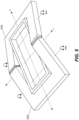
- Figure 5 shows a perspective view of the three-axis accelerometer depicted in Figure 4 , demonstrating the movement of the see-saw proof masses 510a, 510b along the rotation axes RAa, RAb, and the in-plane X and Y axes.
Landscapes
- Physics & Mathematics (AREA)
- General Physics & Mathematics (AREA)
- Pressure Sensors (AREA)
- Micromachines (AREA)
Claims (14)
- MEMS-Beschleunigungsmesser, wobei der Beschleunigungsmesser umfasst:ein Substrat, das eine Substratebene definiert;mindestens eine In-plane-Prüfmasse (201), die dazu ausgelegt ist, sich im Verhältnis zum Substrat entlang mindestens einer ersten Achse und einer zweiten Achse zu bewegen, wobei die erste Achse und zweite Achse parallel zur Substratebene und rechtwinklig zueinander liegen;eine erste Messstruktur (221, 222) zum Messen einer Bewegung der Prüfmasse (201) entlang einer ersten Messachse parallel zur ersten Achse, wobei die erste Messstruktur eine erste bewegliche Messstruktur (222) umfasst, die im Verhältnis zum Substrat beweglich ist;eine zweite Messstruktur (211, 212) zum Messen einer Bewegung der Prüfmasse entlang einer zweiten Messachse parallel zur zweiten Achse, wobei die zweite Messstruktur eine zweite bewegliche Messstruktur (212) umfasst, die im Verhältnis zum Substrat beweglich ist;eine dritte Messstruktur zum Messen einer Bewegung der Prüfmasse entlang der zweiten Messachse, wobei die dritte Messstruktur eine dritte bewegliche Messstruktur umfasst, die im Verhältnis zum Substrat beweglich ist;wobei die mindestens eine In-plane-Prüfmasse (201) mit der ersten beweglichen Messstruktur (222) durch mindestens eine Feder (226a, 226b) verbunden ist, die die Bewegung der mindestens einen In-plane-Prüfmasse (201) und ersten beweglichen Messstruktur (222) entlang der ersten Achse mechanisch koppelt und eine Bewegung der mindestens einen In-plane-Prüfmasse (201) und der ersten beweglichen Messstruktur (222) entlang der zweiten Achse mechanisch entkoppelt; wobeidie mindestens eine In-plane-Prüfmasse (201) mit der zweiten beweglichen Messstruktur (212) durch mindestens eine Feder (216a, 216b) verbunden ist, die die Bewegung der mindestens einen In-plane-Prüfmasse (201) und der zweiten beweglichen Messstruktur (212) entlang der zweiten Achse mechanisch koppelt und eine Bewegung der mindestens einen In-plane-Prüfmasse (201) und der zweiten beweglichen Messstruktur (212) entlang der ersten Achse mechanisch entkoppelt;die mindestens eine In-plane-Prüfmasse mit der dritten beweglichen Messstruktur durch mindestens eine Feder verbunden ist, die die Bewegung der mindestens einen In-plane-Prüfmasse und dritten beweglichen Messstruktur entlang der zweiten Achse mechanisch koppelt und eine Bewegung der mindestens einen In-plane-Prüfmasse und der dritten beweglichen Messstruktur entlang der ersten Achse mechanisch entkoppelt;die erste bewegliche Messstruktur (222) zwei Längsbalken umfasst, die über einen mittigen Querbalken, der von der Mitte jedes Längsbalkens aus vorsteht, verbunden sind, wobei die Längsbalken parallel zur ersten Achse angeordnet sind und der mittige Querbalken parallel zur zweiten Achse angeordnet ist; unddie erste bewegliche Messstruktur (222) zwischen der zweiten (212) und dritten Messstruktur dergestalt positioniert ist, dass die zweite und die dritte Messstruktur auf gegenüberliegenden Seiten der ersten beweglichen Messstruktur (222) positioniert sind.
- MEMS-Beschleunigungsmesser nach Anspruch 1, wobei die erste bewegliche Messstruktur (222) mit mindestens einer ersten feststehenden Stützstruktur (215) durch mindestens eine Feder (227a, 227b) verbunden ist, die die Bewegung der ersten beweglichen Messstruktur (222) und der mindestens einen ersten feststehenden Stützstruktur (215) entlang der zweiten Achse mechanisch koppelt und eine Bewegung der ersten beweglichen Messstruktur (222) und der mindestens einen ersten feststehenden Stützstruktur (215) entlang der ersten Achse mechanisch entkoppelt.
- MEMS-Beschleunigungsmesser nach einem vorhergehenden Anspruch, wobei die erste Messstruktur auch erste feststehende Messstrukturen (221) umfasst, die im Verhältnis zum Substrat feststehend sind.
- MEMS-Beschleunigungsmesser nach Anspruch 3, wobei die erste bewegliche Messstruktur (222) erste bewegliche Elektroden (224) umfasst und die ersten feststehenden Messstrukturen (221) erste feststehende Elektroden (223) umfassen, und wobei die erste Messstruktur dazu ausgelegt ist, die durch eine Bewegung der mindestens einen In-plane-Prüfmasse (201) parallel zur ersten Achse verursachte Kapazitätsänderung zwischen den ersten feststehenden Elektroden (223) und ersten beweglichen Elektroden (224) zu messen.
- MEMS-Beschleunigungsmesser nach Anspruch 3 oder 4, wobei die ersten feststehenden Messstrukturen (221) zwischen den Längsbalken der ersten beweglichen Messstruktur positioniert sind.
- MEMS-Beschleunigungsmesser nach Anspruch 5, wobei die ersten feststehenden Messstrukturen (221) dergestalt positioniert sind, dass auf jeder Seite des mittigen Balkens mindestens eine der ersten feststehenden Messstrukturen positioniert ist.
- MEMS-Beschleunigungsmesser nach Anspruch 5 oder 6, wobei die erste bewegliche Messstruktur (222) mit der mindestens einen In-plane-Prüfmasse (201) durch vier Federn (226a, 226b) verbunden ist, wobei jede der vier Federn an einem der Enden der Längsbalken angeordnet ist.
- MEMS-Beschleunigungsmesser nach Anspruch 2 und einem der Ansprüche 5 bis 7, wobei die erste bewegliche Messstruktur mit den feststehenden Stützstrukturen durch vier Federn (227a, 227b) verbunden ist, wobei jede der vier Federn an einem der Enden der Längsbalken angeordnet ist.
- MEMS-Beschleunigungsmesser nach einem vorhergehenden Anspruch, wobei die erste bewegliche Messstruktur (222) in der Mitte des Beschleunigungsmessers positioniert ist, wenn der Beschleunigungsmesser in Ruhe ist.
- MEMS-Beschleunigungsmesser nach einem vorhergehenden Anspruch, wobei die zweite Messstruktur (211, 212) auch eine zweite feststehende Messstruktur (211) umfasst, die im Verhältnis zum Substrat feststehend ist, und die dritte Messstruktur auch eine dritte feststehende Messstruktur umfasst, die auch im Verhältnis zum Substrat feststehend ist.
- MEMS-Beschleunigungsmesser nach Anspruch 10, wobei die zweite bewegliche Messstruktur (212) mindestens eine zweite bewegliche Elektrode (214) umfasst und die zweite feststehende Messstruktur (211) mindestens eine zweite feststehende Elektrode (213) umfasst, sodass die Kapazität des von der zweiten feststehenden Kammelektrode (213) und zweiten beweglichen Kammelektrode (214) ausgebildeten Kondensators sich mit der Bewegung der mindestens einen In-plane-Prüfmasse (201) parallel zur zweiten Achse ändert; und
wobei die dritte bewegliche Messstruktur mindestens eine dritte bewegliche Elektrode umfasst und die dritte feststehende Messstruktur mindestens eine dritte feststehende Elektrode umfasst, sodass die Kapazität des von der dritten beweglichen Elektrode und der dritten feststehenden Elektrode ausgebildeten Kondensators sich mit der Bewegung der mindestens einen In-plane-Prüfmasse (201) parallel zur zweiten Achse ändert. - MEMS-Beschleunigungsmesser nach einem vorhergehenden Anspruch, wobei es sich bei den Federn um Balkenfedern handelt, die jeweils entlang ihrer Längsachse einer Kompression entgegenwirken und ein Biegen der Feder entlang einer Querachse parallel zur Substratebene gestatten.
- MEMS-Beschleunigungsmesser nach Anspruch 12, wobei jede Balkenfeder auch einem Biegen der Feder entlang einer Querachse rechtwinklig zur Substratebene entgegenwirkt.
- MEMS-Beschleunigungsmesser nach einem vorhergehenden Anspruch, wobei der MEMS-Beschleunigungsmesser ferner einen oder mehrere Stopper (230a, 230b, 230c, 230d) umfasst, die am Substrat oder an einem Deckwafer befestigt sein können und die einer Bewegung der beweglichen Messstrukturen (212, 222) in mindestens einer Richtung rechtwinklig zur Messachse der Messstruktur entgegenwirken.
Applications Claiming Priority (1)
| Application Number | Priority Date | Filing Date | Title |
|---|---|---|---|
| FI20205272 | 2020-03-18 |
Publications (2)
| Publication Number | Publication Date |
|---|---|
| EP3882641A1 EP3882641A1 (de) | 2021-09-22 |
| EP3882641B1 true EP3882641B1 (de) | 2023-02-15 |
Family
ID=74859750
Family Applications (1)
| Application Number | Title | Priority Date | Filing Date |
|---|---|---|---|
| EP21161170.2A Active EP3882641B1 (de) | 2020-03-18 | 2021-03-08 | Mems-beschleunigungsmesser mit mechanisch entkoppelter prüfmasse |
Country Status (3)
| Country | Link |
|---|---|
| US (1) | US11796560B2 (de) |
| EP (1) | EP3882641B1 (de) |
| JP (1) | JP7070746B2 (de) |
Families Citing this family (13)
| Publication number | Priority date | Publication date | Assignee | Title |
|---|---|---|---|---|
| WO2022090955A1 (en) * | 2020-10-30 | 2022-05-05 | Murata Manufacturing Co., Ltd. | Mems gyrocompass |
| CN114487480B (zh) * | 2022-01-14 | 2025-09-16 | 瑞声开泰科技(武汉)有限公司 | 微机电系统加速度计 |
| CN114487482B (zh) * | 2022-01-14 | 2024-08-16 | 瑞声开泰科技(武汉)有限公司 | 加速度传感器 |
| CN114966111B (zh) * | 2022-04-12 | 2025-08-15 | 苏州感测通信息科技有限公司 | 一种叶片式z轴mems加速度计 |
| CN114814293B (zh) * | 2022-06-29 | 2022-09-09 | 成都华托微纳智能传感科技有限公司 | 一种锯齿形梳齿结构的mems加速度计 |
| CN115436660B (zh) * | 2022-08-31 | 2026-01-20 | 瑞声开泰科技(武汉)有限公司 | 一种加速度计 |
| FR3140423B1 (fr) * | 2022-09-30 | 2025-01-03 | Commissariat A L Energie Atomique Et Aux Energies Alternatives | Capteur inertiel de type MEMS à liaison mécanique spécifique |
| FR3140621A1 (fr) * | 2022-10-05 | 2024-04-12 | Commissariat A L'energie Atomique Et Aux Energies Alternatives | Dispositif micro-électromécanique |
| US12498392B2 (en) | 2023-03-09 | 2025-12-16 | Invensense, Inc. | Dual axis accelerometer with compensation electrodes |
| WO2025152080A1 (zh) * | 2024-01-17 | 2025-07-24 | 瑞声开泰科技(武汉)有限公司 | 一种加速度传感器 |
| WO2025152081A1 (zh) * | 2024-01-17 | 2025-07-24 | 瑞声开泰科技(武汉)有限公司 | 一种加速度传感器 |
| CN119104750B (zh) * | 2024-09-14 | 2026-02-27 | 京华芯盛(北京)半导体科技有限公司 | 田字形解耦隔振组合梁框架结构及其高精度四质量双轴微加速度计 |
| CN120490537B (zh) * | 2025-05-15 | 2026-01-30 | 上海工程技术大学 | 一种基于微纳技术的双轴硅电容高精度加速度计 |
Family Cites Families (17)
| Publication number | Priority date | Publication date | Assignee | Title |
|---|---|---|---|---|
| US5817942A (en) * | 1996-02-28 | 1998-10-06 | The Charles Stark Draper Laboratory, Inc. | Capacitive in-plane accelerometer |
| US6065341A (en) * | 1998-02-18 | 2000-05-23 | Denso Corporation | Semiconductor physical quantity sensor with stopper portion |
| JP3498209B2 (ja) * | 1999-10-25 | 2004-02-16 | 株式会社村田製作所 | 外力検知センサ装置 |
| US7784344B2 (en) * | 2007-11-29 | 2010-08-31 | Honeywell International Inc. | Integrated MEMS 3D multi-sensor |
| US8250916B2 (en) * | 2008-08-12 | 2012-08-28 | Hitachi, Ltd. | Inertial sensor |
| CN102119318B (zh) | 2008-08-18 | 2013-10-30 | 株式会社日立制作所 | 微机电系统 |
| TWI374268B (en) * | 2008-09-05 | 2012-10-11 | Ind Tech Res Inst | Multi-axis capacitive accelerometer |
| US8205498B2 (en) * | 2008-11-18 | 2012-06-26 | Industrial Technology Research Institute | Multi-axis capacitive accelerometer |
| DE102009000729B4 (de) | 2009-02-09 | 2022-05-19 | Robert Bosch Gmbh | Sensoranordnung |
| DE102012104601A1 (de) * | 2011-05-31 | 2012-12-06 | Maxim Integrated Gmbh | MEMS-Beschleunigungssensor |
| US8978475B2 (en) * | 2012-02-01 | 2015-03-17 | Fairchild Semiconductor Corporation | MEMS proof mass with split z-axis portions |
| GB2523320A (en) | 2014-02-19 | 2015-08-26 | Atlantic Inertial Systems Ltd | Accelerometers |
| FI126599B (en) | 2014-02-26 | 2017-03-15 | Murata Manufacturing Co | Microelectromechanical frame structure |
| JP6464738B2 (ja) | 2014-12-26 | 2019-02-06 | 株式会社デンソー | 加速度センサ |
| FI127000B (en) | 2015-06-26 | 2017-09-15 | Murata Manufacturing Co | MEMS sensor |
| WO2017051243A1 (en) * | 2015-09-25 | 2017-03-30 | Murata Manufacturing Co., Ltd. | Improved microelectromechanical accelerometer device |
| TWI570054B (zh) | 2015-12-28 | 2017-02-11 | 財團法人工業技術研究院 | 具中央固定座的微機電裝置 |
-
2021
- 2021-03-08 EP EP21161170.2A patent/EP3882641B1/de active Active
- 2021-03-16 US US17/202,736 patent/US11796560B2/en active Active
- 2021-03-17 JP JP2021043415A patent/JP7070746B2/ja active Active
Also Published As
| Publication number | Publication date |
|---|---|
| JP7070746B2 (ja) | 2022-05-18 |
| US11796560B2 (en) | 2023-10-24 |
| JP2021148796A (ja) | 2021-09-27 |
| EP3882641A1 (de) | 2021-09-22 |
| US20210293847A1 (en) | 2021-09-23 |
Similar Documents
| Publication | Publication Date | Title |
|---|---|---|
| EP3882641B1 (de) | Mems-beschleunigungsmesser mit mechanisch entkoppelter prüfmasse | |
| EP3792637B1 (de) | Rauscharmer mehrachsiger mems-beschleunigungsmesser | |
| EP3792638B1 (de) | Rauscharmer mehrachsiger mems-beschleunigungsmesser | |
| US9689676B2 (en) | Yaw-rate sensor | |
| US6705164B2 (en) | Rotation rate sensor | |
| US9278845B2 (en) | MEMS multi-axis gyroscope Z-axis electrode structure | |
| EP3314270B1 (de) | Mems-sensor | |
| CN101639487B (zh) | 三轴加速度传感器 | |
| US8272268B2 (en) | Triaxial acceleration sensor | |
| US20100186507A1 (en) | Micromechanical rotation rate sensor with a coupling bar and suspension spring elements for quadrature suppression | |
| KR101776583B1 (ko) | 멤스 자이로스코프에 사용되는 멤스 링크 기구 | |
| EP3268305B1 (de) | Mikroelektromechanische kapazitive sensorstruktur und vorrichtung | |
| WO2013116522A1 (en) | Mems multi-axis gyroscope z-axis electrode structure | |
| US12474366B2 (en) | Three-axis accelerometer with two masses | |
| IT202000003868A1 (it) | Inclinometro mems avente ridotto errore di rettificazione di vibrazioni | |
| WO2014057623A1 (ja) | 加速度センサ | |
| US12428291B2 (en) | In-plane and out-of-plane accelerometer |
Legal Events
| Date | Code | Title | Description |
|---|---|---|---|
| PUAI | Public reference made under article 153(3) epc to a published international application that has entered the european phase |
Free format text: ORIGINAL CODE: 0009012 |
|
| STAA | Information on the status of an ep patent application or granted ep patent |
Free format text: STATUS: REQUEST FOR EXAMINATION WAS MADE |
|
| 17P | Request for examination filed |
Effective date: 20210308 |
|
| AK | Designated contracting states |
Kind code of ref document: A1 Designated state(s): AL AT BE BG CH CY CZ DE DK EE ES FI FR GB GR HR HU IE IS IT LI LT LU LV MC MK MT NL NO PL PT RO RS SE SI SK SM TR |
|
| GRAP | Despatch of communication of intention to grant a patent |
Free format text: ORIGINAL CODE: EPIDOSNIGR1 |
|
| STAA | Information on the status of an ep patent application or granted ep patent |
Free format text: STATUS: GRANT OF PATENT IS INTENDED |
|
| INTG | Intention to grant announced |
Effective date: 20220915 |
|
| GRAS | Grant fee paid |
Free format text: ORIGINAL CODE: EPIDOSNIGR3 |
|
| GRAA | (expected) grant |
Free format text: ORIGINAL CODE: 0009210 |
|
| STAA | Information on the status of an ep patent application or granted ep patent |
Free format text: STATUS: THE PATENT HAS BEEN GRANTED |
|
| AK | Designated contracting states |
Kind code of ref document: B1 Designated state(s): AL AT BE BG CH CY CZ DE DK EE ES FI FR GB GR HR HU IE IS IT LI LT LU LV MC MK MT NL NO PL PT RO RS SE SI SK SM TR |
|
| REG | Reference to a national code |
Ref country code: CH Ref legal event code: EP Ref country code: GB Ref legal event code: FG4D |
|
| REG | Reference to a national code |
Ref country code: DE Ref legal event code: R096 Ref document number: 602021001377 Country of ref document: DE |
|
| REG | Reference to a national code |
Ref country code: AT Ref legal event code: REF Ref document number: 1548477 Country of ref document: AT Kind code of ref document: T Effective date: 20230315 Ref country code: IE Ref legal event code: FG4D |
|
| REG | Reference to a national code |
Ref country code: LT Ref legal event code: MG9D |
|
| REG | Reference to a national code |
Ref country code: NL Ref legal event code: MP Effective date: 20230215 |
|
| REG | Reference to a national code |
Ref country code: AT Ref legal event code: MK05 Ref document number: 1548477 Country of ref document: AT Kind code of ref document: T Effective date: 20230215 |
|
| PG25 | Lapsed in a contracting state [announced via postgrant information from national office to epo] |
Ref country code: RS Free format text: LAPSE BECAUSE OF FAILURE TO SUBMIT A TRANSLATION OF THE DESCRIPTION OR TO PAY THE FEE WITHIN THE PRESCRIBED TIME-LIMIT Effective date: 20230215 Ref country code: PT Free format text: LAPSE BECAUSE OF FAILURE TO SUBMIT A TRANSLATION OF THE DESCRIPTION OR TO PAY THE FEE WITHIN THE PRESCRIBED TIME-LIMIT Effective date: 20230615 Ref country code: NO Free format text: LAPSE BECAUSE OF FAILURE TO SUBMIT A TRANSLATION OF THE DESCRIPTION OR TO PAY THE FEE WITHIN THE PRESCRIBED TIME-LIMIT Effective date: 20230515 Ref country code: NL Free format text: LAPSE BECAUSE OF FAILURE TO SUBMIT A TRANSLATION OF THE DESCRIPTION OR TO PAY THE FEE WITHIN THE PRESCRIBED TIME-LIMIT Effective date: 20230215 Ref country code: LV Free format text: LAPSE BECAUSE OF FAILURE TO SUBMIT A TRANSLATION OF THE DESCRIPTION OR TO PAY THE FEE WITHIN THE PRESCRIBED TIME-LIMIT Effective date: 20230215 Ref country code: LT Free format text: LAPSE BECAUSE OF FAILURE TO SUBMIT A TRANSLATION OF THE DESCRIPTION OR TO PAY THE FEE WITHIN THE PRESCRIBED TIME-LIMIT Effective date: 20230215 Ref country code: HR Free format text: LAPSE BECAUSE OF FAILURE TO SUBMIT A TRANSLATION OF THE DESCRIPTION OR TO PAY THE FEE WITHIN THE PRESCRIBED TIME-LIMIT Effective date: 20230215 Ref country code: ES Free format text: LAPSE BECAUSE OF FAILURE TO SUBMIT A TRANSLATION OF THE DESCRIPTION OR TO PAY THE FEE WITHIN THE PRESCRIBED TIME-LIMIT Effective date: 20230215 Ref country code: AT Free format text: LAPSE BECAUSE OF FAILURE TO SUBMIT A TRANSLATION OF THE DESCRIPTION OR TO PAY THE FEE WITHIN THE PRESCRIBED TIME-LIMIT Effective date: 20230215 |
|
| PG25 | Lapsed in a contracting state [announced via postgrant information from national office to epo] |
Ref country code: SE Free format text: LAPSE BECAUSE OF FAILURE TO SUBMIT A TRANSLATION OF THE DESCRIPTION OR TO PAY THE FEE WITHIN THE PRESCRIBED TIME-LIMIT Effective date: 20230215 Ref country code: PL Free format text: LAPSE BECAUSE OF FAILURE TO SUBMIT A TRANSLATION OF THE DESCRIPTION OR TO PAY THE FEE WITHIN THE PRESCRIBED TIME-LIMIT Effective date: 20230215 Ref country code: IS Free format text: LAPSE BECAUSE OF FAILURE TO SUBMIT A TRANSLATION OF THE DESCRIPTION OR TO PAY THE FEE WITHIN THE PRESCRIBED TIME-LIMIT Effective date: 20230615 Ref country code: GR Free format text: LAPSE BECAUSE OF FAILURE TO SUBMIT A TRANSLATION OF THE DESCRIPTION OR TO PAY THE FEE WITHIN THE PRESCRIBED TIME-LIMIT Effective date: 20230516 Ref country code: FI Free format text: LAPSE BECAUSE OF FAILURE TO SUBMIT A TRANSLATION OF THE DESCRIPTION OR TO PAY THE FEE WITHIN THE PRESCRIBED TIME-LIMIT Effective date: 20230215 |
|
| PG25 | Lapsed in a contracting state [announced via postgrant information from national office to epo] |
Ref country code: SM Free format text: LAPSE BECAUSE OF FAILURE TO SUBMIT A TRANSLATION OF THE DESCRIPTION OR TO PAY THE FEE WITHIN THE PRESCRIBED TIME-LIMIT Effective date: 20230215 Ref country code: RO Free format text: LAPSE BECAUSE OF FAILURE TO SUBMIT A TRANSLATION OF THE DESCRIPTION OR TO PAY THE FEE WITHIN THE PRESCRIBED TIME-LIMIT Effective date: 20230215 Ref country code: EE Free format text: LAPSE BECAUSE OF FAILURE TO SUBMIT A TRANSLATION OF THE DESCRIPTION OR TO PAY THE FEE WITHIN THE PRESCRIBED TIME-LIMIT Effective date: 20230215 Ref country code: DK Free format text: LAPSE BECAUSE OF FAILURE TO SUBMIT A TRANSLATION OF THE DESCRIPTION OR TO PAY THE FEE WITHIN THE PRESCRIBED TIME-LIMIT Effective date: 20230215 Ref country code: CZ Free format text: LAPSE BECAUSE OF FAILURE TO SUBMIT A TRANSLATION OF THE DESCRIPTION OR TO PAY THE FEE WITHIN THE PRESCRIBED TIME-LIMIT Effective date: 20230215 |
|
| REG | Reference to a national code |
Ref country code: DE Ref legal event code: R097 Ref document number: 602021001377 Country of ref document: DE |
|
| PG25 | Lapsed in a contracting state [announced via postgrant information from national office to epo] |
Ref country code: SK Free format text: LAPSE BECAUSE OF FAILURE TO SUBMIT A TRANSLATION OF THE DESCRIPTION OR TO PAY THE FEE WITHIN THE PRESCRIBED TIME-LIMIT Effective date: 20230215 |
|
| REG | Reference to a national code |
Ref country code: BE Ref legal event code: MM Effective date: 20230331 |
|
| PLBE | No opposition filed within time limit |
Free format text: ORIGINAL CODE: 0009261 |
|
| STAA | Information on the status of an ep patent application or granted ep patent |
Free format text: STATUS: NO OPPOSITION FILED WITHIN TIME LIMIT |
|
| PG25 | Lapsed in a contracting state [announced via postgrant information from national office to epo] |
Ref country code: LU Free format text: LAPSE BECAUSE OF NON-PAYMENT OF DUE FEES Effective date: 20230308 |
|
| PG25 | Lapsed in a contracting state [announced via postgrant information from national office to epo] |
Ref country code: MC Free format text: LAPSE BECAUSE OF FAILURE TO SUBMIT A TRANSLATION OF THE DESCRIPTION OR TO PAY THE FEE WITHIN THE PRESCRIBED TIME-LIMIT Effective date: 20230215 |
|
| REG | Reference to a national code |
Ref country code: IE Ref legal event code: MM4A |
|
| 26N | No opposition filed |
Effective date: 20231116 |
|
| PG25 | Lapsed in a contracting state [announced via postgrant information from national office to epo] |
Ref country code: SI Free format text: LAPSE BECAUSE OF FAILURE TO SUBMIT A TRANSLATION OF THE DESCRIPTION OR TO PAY THE FEE WITHIN THE PRESCRIBED TIME-LIMIT Effective date: 20230215 Ref country code: MC Free format text: LAPSE BECAUSE OF FAILURE TO SUBMIT A TRANSLATION OF THE DESCRIPTION OR TO PAY THE FEE WITHIN THE PRESCRIBED TIME-LIMIT Effective date: 20230215 Ref country code: IE Free format text: LAPSE BECAUSE OF NON-PAYMENT OF DUE FEES Effective date: 20230308 Ref country code: FR Free format text: LAPSE BECAUSE OF NON-PAYMENT OF DUE FEES Effective date: 20230415 |
|
| PG25 | Lapsed in a contracting state [announced via postgrant information from national office to epo] |
Ref country code: BE Free format text: LAPSE BECAUSE OF NON-PAYMENT OF DUE FEES Effective date: 20230331 |
|
| PG25 | Lapsed in a contracting state [announced via postgrant information from national office to epo] |
Ref country code: IT Free format text: LAPSE BECAUSE OF FAILURE TO SUBMIT A TRANSLATION OF THE DESCRIPTION OR TO PAY THE FEE WITHIN THE PRESCRIBED TIME-LIMIT Effective date: 20230215 |
|
| REG | Reference to a national code |
Ref country code: CH Ref legal event code: PL |
|
| PG25 | Lapsed in a contracting state [announced via postgrant information from national office to epo] |
Ref country code: BG Free format text: LAPSE BECAUSE OF FAILURE TO SUBMIT A TRANSLATION OF THE DESCRIPTION OR TO PAY THE FEE WITHIN THE PRESCRIBED TIME-LIMIT Effective date: 20230215 |
|
| PG25 | Lapsed in a contracting state [announced via postgrant information from national office to epo] |
Ref country code: BG Free format text: LAPSE BECAUSE OF FAILURE TO SUBMIT A TRANSLATION OF THE DESCRIPTION OR TO PAY THE FEE WITHIN THE PRESCRIBED TIME-LIMIT Effective date: 20230215 |
|
| PG25 | Lapsed in a contracting state [announced via postgrant information from national office to epo] |
Ref country code: CH Free format text: LAPSE BECAUSE OF NON-PAYMENT OF DUE FEES Effective date: 20240331 |
|
| PG25 | Lapsed in a contracting state [announced via postgrant information from national office to epo] |
Ref country code: CY Free format text: LAPSE BECAUSE OF FAILURE TO SUBMIT A TRANSLATION OF THE DESCRIPTION OR TO PAY THE FEE WITHIN THE PRESCRIBED TIME-LIMIT; INVALID AB INITIO Effective date: 20210308 |
|
| PG25 | Lapsed in a contracting state [announced via postgrant information from national office to epo] |
Ref country code: HU Free format text: LAPSE BECAUSE OF FAILURE TO SUBMIT A TRANSLATION OF THE DESCRIPTION OR TO PAY THE FEE WITHIN THE PRESCRIBED TIME-LIMIT; INVALID AB INITIO Effective date: 20210308 |
|
| GBPC | Gb: european patent ceased through non-payment of renewal fee |
Effective date: 20250308 |
|
| PG25 | Lapsed in a contracting state [announced via postgrant information from national office to epo] |
Ref country code: TR Free format text: LAPSE BECAUSE OF FAILURE TO SUBMIT A TRANSLATION OF THE DESCRIPTION OR TO PAY THE FEE WITHIN THE PRESCRIBED TIME-LIMIT Effective date: 20230215 |
|
| PG25 | Lapsed in a contracting state [announced via postgrant information from national office to epo] |
Ref country code: GB Free format text: LAPSE BECAUSE OF NON-PAYMENT OF DUE FEES Effective date: 20250308 |
|
| PGFP | Annual fee paid to national office [announced via postgrant information from national office to epo] |
Ref country code: DE Payment date: 20260319 Year of fee payment: 6 |