EP3883121A1 - Haushaltsgerät und verfahren zum betreiben eines haushaltsgerätes - Google Patents
Haushaltsgerät und verfahren zum betreiben eines haushaltsgerätes Download PDFInfo
- Publication number
- EP3883121A1 EP3883121A1 EP21158179.8A EP21158179A EP3883121A1 EP 3883121 A1 EP3883121 A1 EP 3883121A1 EP 21158179 A EP21158179 A EP 21158179A EP 3883121 A1 EP3883121 A1 EP 3883121A1
- Authority
- EP
- European Patent Office
- Prior art keywords
- synchronous motor
- phase synchronous
- phase
- electric drive
- longitudinal
- Prior art date
- Legal status (The legal status is an assumption and is not a legal conclusion. Google has not performed a legal analysis and makes no representation as to the accuracy of the status listed.)
- Granted
Links
Images




Classifications
-
- H—ELECTRICITY
- H02—GENERATION; CONVERSION OR DISTRIBUTION OF ELECTRIC POWER
- H02P—CONTROL OR REGULATION OF ELECTRIC MOTORS, ELECTRIC GENERATORS OR DYNAMO-ELECTRIC CONVERTERS; CONTROLLING TRANSFORMERS, REACTORS OR CHOKE COILS
- H02P21/00—Arrangements or methods for the control of electric machines by vector control, e.g. by control of field orientation
- H02P21/04—Arrangements or methods for the control of electric machines by vector control, e.g. by control of field orientation specially adapted for very low speeds
-
- H—ELECTRICITY
- H02—GENERATION; CONVERSION OR DISTRIBUTION OF ELECTRIC POWER
- H02P—CONTROL OR REGULATION OF ELECTRIC MOTORS, ELECTRIC GENERATORS OR DYNAMO-ELECTRIC CONVERTERS; CONTROLLING TRANSFORMERS, REACTORS OR CHOKE COILS
- H02P21/00—Arrangements or methods for the control of electric machines by vector control, e.g. by control of field orientation
- H02P21/24—Vector control not involving the use of rotor position or rotor speed sensors
-
- F—MECHANICAL ENGINEERING; LIGHTING; HEATING; WEAPONS; BLASTING
- F04—POSITIVE - DISPLACEMENT MACHINES FOR LIQUIDS; PUMPS FOR LIQUIDS OR ELASTIC FLUIDS
- F04B—POSITIVE-DISPLACEMENT MACHINES FOR LIQUIDS; PUMPS
- F04B49/00—Control, e.g. of pump delivery, or pump pressure of, or safety measures for, machines, pumps, or pumping installations, not otherwise provided for, or of interest apart from, groups F04B1/00 - F04B47/00
- F04B49/02—Stopping, starting, unloading or idling control
- F04B49/03—Stopping, starting, unloading or idling control by means of valves
-
- F—MECHANICAL ENGINEERING; LIGHTING; HEATING; WEAPONS; BLASTING
- F04—POSITIVE - DISPLACEMENT MACHINES FOR LIQUIDS; PUMPS FOR LIQUIDS OR ELASTIC FLUIDS
- F04B—POSITIVE-DISPLACEMENT MACHINES FOR LIQUIDS; PUMPS
- F04B49/00—Control, e.g. of pump delivery, or pump pressure of, or safety measures for, machines, pumps, or pumping installations, not otherwise provided for, or of interest apart from, groups F04B1/00 - F04B47/00
- F04B49/06—Control using electricity
- F04B49/065—Control using electricity and making use of computers
-
- F—MECHANICAL ENGINEERING; LIGHTING; HEATING; WEAPONS; BLASTING
- F25—REFRIGERATION OR COOLING; COMBINED HEATING AND REFRIGERATION SYSTEMS; HEAT PUMP SYSTEMS; MANUFACTURE OR STORAGE OF ICE; LIQUEFACTION SOLIDIFICATION OF GASES
- F25B—REFRIGERATION MACHINES, PLANTS OR SYSTEMS; COMBINED HEATING AND REFRIGERATION SYSTEMS; HEAT PUMP SYSTEMS
- F25B31/00—Compressor arrangements
- F25B31/02—Compressor arrangements of motor-compressor units
- F25B31/023—Compressor arrangements of motor-compressor units with compressor of reciprocating-piston type
-
- H—ELECTRICITY
- H02—GENERATION; CONVERSION OR DISTRIBUTION OF ELECTRIC POWER
- H02P—CONTROL OR REGULATION OF ELECTRIC MOTORS, ELECTRIC GENERATORS OR DYNAMO-ELECTRIC CONVERTERS; CONTROLLING TRANSFORMERS, REACTORS OR CHOKE COILS
- H02P21/00—Arrangements or methods for the control of electric machines by vector control, e.g. by control of field orientation
- H02P21/14—Estimation or adaptation of machine parameters, e.g. flux, current or voltage
- H02P21/18—Estimation of position or speed
-
- H—ELECTRICITY
- H02—GENERATION; CONVERSION OR DISTRIBUTION OF ELECTRIC POWER
- H02P—CONTROL OR REGULATION OF ELECTRIC MOTORS, ELECTRIC GENERATORS OR DYNAMO-ELECTRIC CONVERTERS; CONTROLLING TRANSFORMERS, REACTORS OR CHOKE COILS
- H02P21/00—Arrangements or methods for the control of electric machines by vector control, e.g. by control of field orientation
- H02P21/22—Current control, e.g. using a current control loop
-
- H—ELECTRICITY
- H02—GENERATION; CONVERSION OR DISTRIBUTION OF ELECTRIC POWER
- H02P—CONTROL OR REGULATION OF ELECTRIC MOTORS, ELECTRIC GENERATORS OR DYNAMO-ELECTRIC CONVERTERS; CONTROLLING TRANSFORMERS, REACTORS OR CHOKE COILS
- H02P21/00—Arrangements or methods for the control of electric machines by vector control, e.g. by control of field orientation
- H02P21/36—Arrangements for braking or slowing; Four quadrant control
-
- H—ELECTRICITY
- H02—GENERATION; CONVERSION OR DISTRIBUTION OF ELECTRIC POWER
- H02P—CONTROL OR REGULATION OF ELECTRIC MOTORS, ELECTRIC GENERATORS OR DYNAMO-ELECTRIC CONVERTERS; CONTROLLING TRANSFORMERS, REACTORS OR CHOKE COILS
- H02P6/00—Arrangements for controlling synchronous motors or other dynamo-electric motors using electronic commutation dependent on the rotor position; Electronic commutators therefor
- H02P6/14—Electronic commutators
- H02P6/16—Circuit arrangements for detecting position
- H02P6/18—Circuit arrangements for detecting position without separate position detecting elements
- H02P6/183—Circuit arrangements for detecting position without separate position detecting elements using an injected high frequency signal
-
- H—ELECTRICITY
- H02—GENERATION; CONVERSION OR DISTRIBUTION OF ELECTRIC POWER
- H02P—CONTROL OR REGULATION OF ELECTRIC MOTORS, ELECTRIC GENERATORS OR DYNAMO-ELECTRIC CONVERTERS; CONTROLLING TRANSFORMERS, REACTORS OR CHOKE COILS
- H02P6/00—Arrangements for controlling synchronous motors or other dynamo-electric motors using electronic commutation dependent on the rotor position; Electronic commutators therefor
- H02P6/24—Arrangements for stopping
-
- H—ELECTRICITY
- H02—GENERATION; CONVERSION OR DISTRIBUTION OF ELECTRIC POWER
- H02P—CONTROL OR REGULATION OF ELECTRIC MOTORS, ELECTRIC GENERATORS OR DYNAMO-ELECTRIC CONVERTERS; CONTROLLING TRANSFORMERS, REACTORS OR CHOKE COILS
- H02P2203/00—Indexing scheme relating to controlling arrangements characterised by the means for detecting the position of the rotor
- H02P2203/11—Determination or estimation of the rotor position or other motor parameters based on the analysis of high-frequency signals
-
- H—ELECTRICITY
- H02—GENERATION; CONVERSION OR DISTRIBUTION OF ELECTRIC POWER
- H02P—CONTROL OR REGULATION OF ELECTRIC MOTORS, ELECTRIC GENERATORS OR DYNAMO-ELECTRIC CONVERTERS; CONTROLLING TRANSFORMERS, REACTORS OR CHOKE COILS
- H02P2205/00—Indexing scheme relating to controlling arrangements characterised by the control loops
- H02P2205/07—Speed loop, i.e. comparison of the motor speed with a speed reference
Definitions
- the invention relates to a method for operating a household appliance, which comprises a field-oriented controlled electric drive, and a corresponding household appliance.
- the DE 10 2017 211 217 A1 discloses a household refrigeration appliance which has a refrigerant circuit with a compressor and a speed-controlled electric drive.
- the control of the electric drive is a field-oriented control and the electric drive comprises a converter and a permanently excited three-phase synchronous motor connected downstream of the converter, which is part of the compressor or is intended to drive the compressor.
- the household refrigeration device is set up to control the converter in such a way that when the compressor is switched on, the speed of the three-phase synchronous motor is at least approximately equal to a predetermined speed due to control by the converter, to control the converter in such a way to switch off the switched-on compressor that the speed of the three-phase synchronous motor increases reduced until the speed reaches a predetermined minimum speed, and then to control the converter in such a way that the three-phase synchronous motor is switched off for at least a predetermined period of time.
- the DE 10 2008 029 910 A1 discloses a household dishwasher which has a pump and a field-oriented controlled electric drive.
- the electric drive comprises a converter and a permanently excited three-phase synchronous motor connected downstream of the converter, which drives the pump.
- the object of the invention is to provide an improved method for operating a household appliance which has a speed-controlled electric drive, the control of which is a field-oriented control and the motor of which is a permanent-magnet three-phase synchronous motor that is part of a component of the household appliance or is intended to drive this component.
- Another aspect of the invention relates to a household appliance, having a component and a regulated electric drive, which has a permanently excited three-phase synchronous motor, an actuator designed in particular as a converter for controlling the three-phase synchronous motor and a field-oriented control system for controlling the actuator, the three-phase synchronous motor having a stator and a with respect to the stator rotatably mounted rotor and part of the component or is provided to drive this component, and the household appliance is designed to carry out the method according to the invention.
- the household appliance includes the regulated electric drive, the motor of which is a permanently excited three-phase synchronous motor.
- the permanent magnet three-phase synchronous motor is e.g. a brushless direct current motor.
- the electric drive also includes the actuator which controls the three-phase synchronous motor, i.e. supplies the three-phase synchronous motor with the supply voltage.
- the supply voltage is a three-phase voltage, the basic frequency of which is set by the speed control and the desired target speed.
- the actuator is in particular a converter which is preferably operated by means of pulse-width modulation.
- the regulation of the regulated electric drive controls the actuator or the converter and is a field-oriented regulation.
- a field-oriented control usually forms a cascade structure with internal current control loops on which an external speed control loop is superimposed.
- the field-oriented control thus comprises, in particular, a cascade structure with an internal current control loop having a current regulator, on which an external speed control loop is superimposed.
- the current controller is in particular a PI controller, that is to say preferably a controller with a proportional and an integral component.
- the field-oriented regulation is preferably a discrete or digital field-oriented regulation.
- the clock or control frequency of the discrete or digital field-oriented control and thus of the current controller is preferably greater than 1 kHz, e.g. 4 kHz.
- the angular position of the rotor relative to the stator of the three-phase synchronous motor is determined as a function of the so-called longitudinal and transverse currents, which are known in principle to the person skilled in the art, and which can be calculated from the phase currents of the three-phase synchronous motor, and a mathematical model of the three-phase synchronous motor, which is also known as Observer is designated, determine.
- the angular position of the rotor relative to the stator is thus determined in particular without a sensor.
- the supply voltage generated by the actuator and provided for operating the three-phase synchronous motor is not superimposed with the high-frequency voltage until the limit speed has been reached, whereby the phase currents of the three-phase synchronous motor have corresponding high-frequency current components.
- This is called "high frequency injection (HFI)" in English.
- HFI high frequency injection
- the limit speed is preferably between 600 and 1400 revolutions per minute, in particular around 1000 revolutions per minute.
- the high-frequency voltage and thus the high-frequency current components preferably have a frequency greater than 1 kHz, preferably greater than 2 kHz.
- the controlled electric drive is operated with speed control by means of the field-oriented control and depending on an angular position of the rotor relative to the stator determined by means of the longitudinal and transverse currents and the mathematical model of the three-phase synchronous motor, i.e. the angular position of the rotor is operated during the operating phase determined as a function of the longitudinal and transverse currents driving the three-phase synchronous motor and the mathematical model of the three-phase synchronous motor.
- the supply voltage generated by the actuator and provided for operating the three-phase synchronous motor is preferably superimposed with the high-frequency voltage only after the limit frequency has been reached, i.e. the actuator is preferably operated without the superimposed high-frequency voltage during the operating phase and during the part of the braking phase until the limit frequency is reached. This can have a positive effect on the energy consumption of the electric drive and thus the household appliance.
- this comprises generating a control signal for the actuator by superimposing a signal assigned to the high-frequency voltage on the signal generated by the current regulator and assigned to the supply voltage.
- the household appliance according to the invention is thus preferably set up to generate a control signal for the actuator by superimposing a signal generated by the current regulator and assigned to the supply voltage with a signal assigned to the high-frequency voltage.
- phase currents of the three-phase motor are transformed into longitudinal and transverse currents.
- the longitudinal and transverse currents are used for the current control circuit in order to obtain a signal assigned to the supply voltage for controlling the actuator.
- a current regulator is assigned to the longitudinal flow and the cross flow.
- the signal assigned to the high-frequency voltage is preferably only superimposed on the signal generated by the current regulator assigned to the direct current.
- the setpoint value of the longitudinal current is equal to zero.
- the field-oriented control is preferably based on the so-called maximum torque per ampere principle, in order to reduce the energy consumption of the electric drive and thus of the household appliance, especially when the longitudinal and transverse inductances of the three-phase synchronous motor are of different sizes.
- the nominal value of the longitudinal current is not set to zero or to a fixed value, but rather based on a relationship between the longitudinal and transverse inductances and on the basis of the signal determined by the external speed control loop, which is assigned to the torque to be generated by the three-phase synchronous motor. Since this relationship is a non-linear one, the setpoint values of the longitudinal and cross flow are preferably stored in a look-up table.
- the signal assigned to the high-frequency voltage can, for example, be sinusoidal. It is preferably rectangular.
- the current regulator is preferably operated with a regulator frequency which is equal to the frequency of the high-frequency voltage or of the signal assigned to the high-frequency voltage.
- the frequency of the high-frequency voltage or of the signal assigned to the high-frequency voltage is an integral multiple of the controller frequency.
- the method according to the invention has according to a preferred one Variant, a discrete measurement of the longitudinal and transverse currents at least during the start-up phase with twice the frequency of the frequency of the high-frequency voltage, the measurements being clocked in such a way that when two measurements are carried out one after the other, one of the measurements is at the maximum and the other measurement is at the minimum of the measured ones Currents take place.
- the household appliance according to the invention is thus designed according to a preferred embodiment in such a way that it measures the longitudinal and transverse currents at least during the start-up phase at twice the frequency of the frequency of the high-frequency voltage, the measurements being clocked in such a way that one of the measurements is carried out in two consecutive measurements at the maximum and the other measurement at the minimum of the measured currents.
- the high-frequency current components of the longitudinal and transverse currents can then be determined by forming the difference between the measured corresponding currents of two consecutive measurements.
- the household appliance is, for example, a household washing machine with a rotatably mounted laundry drum as the component driven by the electric drive.
- the household appliance is, for example, a household dishwasher with a drain pump as the component.
- the component is preferably a compressor which comprises a compression chamber and is provided for compressing a fluid.
- An example of a household appliance with a compressor is a household tumble dryer which comprises a heat pump circuit comprising the compressor and the regulated electric drive.
- a household appliance with a compressor is a household refrigerator which has a heat-insulated body with a coolable inner container that delimits a coolable interior provided for storing food, a refrigerant circuit provided for cooling the coolable interior with a coolant as the fluid and the compressor, and includes the regulated electric drive.
- a household refrigerator As a household refrigerator, it includes the heat-insulated body with the inner container that delimits the interior space that can be cooled.
- the coolable interior is intended for storing food and is cooled by means of the refrigerant circuit.
- the coolable interior can preferably be closed by means of a door leaf.
- the door leaf is preferably mounted pivotably with respect to an axis which preferably runs vertically. When open, the coolable interior is accessible.
- the refrigerant circuit as such is known in principle to the person skilled in the art and comprises the compressor and in particular a condenser connected downstream of the compressor, a throttle device connected after the condenser and an evaporator arranged between the throttle device and the compressor.
- the compression chamber of the compressor preferably comprises an inlet and an outlet, a piston mounted displaceably within the compression chamber, and a crankshaft.
- the rotor of the three-phase synchronous motor is coupled to the piston via the crankshaft, so that when the compressor is in operation, the piston is able to reduce a volume enclosed by the compressor chamber and the piston for compressing the fluid by means of the three-phase synchronous motor, with the piston in a certain position relative to the compression chamber the volume is minimal and in a further specific position of the piston relative to the compression chamber the volume is maximal.
- a compressor is usually referred to as a reciprocating compressor.
- the actuator can then preferably be activated at the end of the braking phase in such a way that it comes to a standstill for the standstill of the three-phase synchronous motor away from the specific position.
- the three-phase synchronous motor is operated, in particular, at a speed determined or specified, for example, by an electronic control device or a temperature regulator of the household refrigerator.
- Reciprocating compressors have a characteristic torque curve. This can depend on the load point, but also on the speed of the three-phase synchronous motor. Also mechanical conditions of the compressor, such as a The moment of inertia of rotating components of the compressor can have an effect on the operation of the three-phase synchronous motor.
- the volume In a certain position of the piston relative to the compression chamber, the volume is minimal. This particular position is commonly referred to as top dead center.
- the volume is at a maximum.
- This further specific position is usually referred to as bottom dead center.
- the three-phase synchronous motor moves the piston from its specific position, i.e. from its top dead center, to its further specific position, i.e. into its bottom dead center, the volume increases and the compressor sucks in the fluid through its inlet.
- the three-phase synchronous motor moves the piston from its further specific position, that is, from its bottom dead center, to its specific position, that is, its top dead center, the volume is reduced and the compressor compresses the fluid in the compressor chamber until the outlet is at the top Dead center opens so that the compressed fluid can reach the condenser.
- the Fig. 1 shows a perspective view of a household refrigerator 1 as an example of a household appliance that has a component and a regulated electric drive that has a permanently excited three-phase synchronous motor, an actuator designed in particular as a converter for controlling the three-phase synchronous motor and a field-oriented control system for controlling the actuator,
- the Three-phase synchronous motor comprises a stator and a rotor mounted rotatably with respect to the stator and part of the component is or is intended to drive this component.
- the household refrigeration appliance 1 comprises, in particular, a heat-insulated body 10 with an inner container 2 which delimits an interior 3 that can be cooled.
- the coolable interior 3 is provided for storing food, not shown in detail.
- the household refrigerator 1 has a pivotable door leaf 4 for closing the coolable interior 3.
- the door leaf 4 is mounted pivotably in particular with respect to a vertically extending axis. With the door leaf 4 open, as in the Fig. 1 shown, the coolable interior 3 is accessible.
- a plurality of door racks 5 for storing food are arranged on the side of the door leaf 4 directed in the direction of the coolable interior 3.
- a plurality of shelves 6 for storing food are arranged and in the lower region of the coolable interior 3 there is in particular a drawer 7 in which food can also be stored.
- the household refrigerator 1 comprises one in the Fig. 2 shown refrigerant circuit 20 for cooling the coolable interior 3.
- the refrigerant circuit 20 comprises a refrigerant not shown in detail but known in principle to the person skilled in the art, a compressor 21, a condenser 22 downstream of the compressor 21, a throttle device downstream of the condenser 22 23, which is designed in particular as a throttle or capillary tube, and an evaporator 24, which is arranged between the throttle device 23 and the compressor 21.
- the compressor 21 is preferably arranged within a machine room of the household refrigeration appliance 1, which is in particular behind the drawer 7.
- the compressor 21 is designed as a reciprocating compressor and in the Fig. 3 shown in more detail.
- the compressor 21 comprises a compression chamber 31 with an inlet 32 and with an outlet 33 for the refrigerant, and a piston 34 displaceably mounted within the compression chamber 31 Principle is known.
- the compressor 21 comprises a crankshaft 35 and a three-phase synchronous motor 36.
- the compressor 21 is an example of the above-mentioned component.
- the three-phase synchronous motor 36 is in particular a permanent-magnet three-phase synchronous motor, preferably a brushless direct current motor, and comprises a stator 37 and a rotor 38 rotatably mounted relative to the stator 37.
- One of the ends of the crankshaft 35 is connected to the piston 34 and the other end of the crankshaft 35 is coupled to the rotor 38 of the three-phase synchronous motor 36, so that when the domestic refrigerator 1 or the compressor 21 is operated as intended, the piston 34 is able to reduce a volume 39 enclosed by the compressor chamber 31 and the piston 34 for compressing the coolant by means of the three-phase synchronous motor 36.
- the household refrigerator 1 comprises an electronic control device 8 which is set up to control the refrigerant circuit 20, in particular the compressor 21 of the refrigerant circuit 20, in such a way that the coolable interior 3 has at least approximately a predefined or predefinable setpoint temperature.
- the electronic control device 8 is preferably set up in such a way that it regulates the temperature of the coolable interior 3.
- the household refrigerator 1 can have at least one temperature sensor, not shown in detail, and connected to the electronic control device 8.
- the household refrigerator 1 in the case of the present exemplary embodiment comprises one in the Fig. 4 Field-oriented controlled electric drive 40 shown, which has the three-phase synchronous motor 36 of the compressor 21. If necessary, the three-phase synchronous motor is to 36 n corresponding to a predetermined by the electronic control device 8 target speed driven. N to the target rotational speed is calculated in particular by the electronic control device 8 due to an intended cooling the coolable interior 3 or predetermined, for example due to the current temperature and the target temperature of the coolable interior. 3
- the three-phase synchronous motor 36 has a series inductance L d and a transverse inductance L q , which differ in the case of the present exemplary embodiment.
- the characteristic diagrams for the series inductance L d and the transverse inductance L q were measured
- the electric drive 40 comprises an actuator for driving the three-phase synchronous motor 36.
- the actuator is designed and generated as a converter 41 a three-phase supply voltage in the operation of the electric drive 40, the fundamental wave has an amplitude and a fundamental frequency f which is to indirectly dependent n of the target rotational speed and an actual rotational speed n is the three-phase synchronous motor 36th
- the field-oriented controlled electric drive 40 has a measuring device 42 by means of which the electrical phase currents i 1,2,3 of the three-phase synchronous motor 36 are measured and the actual speed of the three-phase synchronous motor 36 is determined without a sensor.
- the measuring device 42 is also provided to calculate transformed transverse and longitudinal currents i q , i d from the phase currents i 1,2,3 , as is known in principle to the person skilled in the art.
- the actual speed n ist of the three-phase synchronous motor 36 can be calculated from the transverse and longitudinal currents i q , i d and a mathematical model of the three-phase motor 36, as is known in principle to the person skilled in the art.
- the field-oriented controlled electric drive 40 has a field-oriented control 43 which controls the converter 41.
- the field-oriented control 43 forms a cascade structure with internal current control loops on which an external speed control loop is superimposed, as is known in principle to the person skilled in the art.
- the Fig. 5 partially shows this structure.
- the current control loops preferably comprise a first current regulator 51 for the cross-flow i q and a second current regulator 52 for the longitudinal current i d .
- the two current regulators 51, 52 are in particular PI regulators.
- the field-oriented control 43 or the measuring device 42 is designed in the case of the present exemplary embodiment in such a way that it converts the phase currents i 1,2,3 of the three-phase synchronous motor 36 into rotor-fixed longitudinal and transverse current actual values i s related to the rotor of the three-phase synchronous motor 36 , d , i s, q transformed.
- the deviation between the setpoint i q, setpoint of the cross current i q and the cross current actual value i s, q is the input signal for the first current regulator 51
- the deviation between the longitudinal current setpoint value i d, soll and the linear current actual value i s, d is the input signal for the second current regulator 52.
- the output signals u q , u d of the two current regulators 51, 52 correspond to transformed electrical voltages which are transformed into signals u w suitable for driving the converter 41 by means of a transformation 54 known in principle to a person skilled in the art.
- the cross- current setpoint value i q, soll results from this external speed control loop, which has a controller 53 and which is calculated as a function of the setpoint speed n soll and the actual speed n ist.
- the controller 53 is in particular a PI controller.
- the longitudinal current setpoint value i d, soll is equal to zero.
- the field-oriented control 43 is preferably a discrete or digital field-oriented control 43.
- the clock or control frequency of the discrete or digital field-oriented control 43 and thus of the two current regulators 51, 52 is, for example, 4 kHz.
- the field-oriented control 43 it is necessary to know the angular position of the rotor 38 relative to the stator 37 of the three-phase synchronous motor 36.
- the angular position is determined without a sensor or without an encoder.
- the field-oriented controlled electric drive 40 is operated with speed control by means of the field-oriented control 43 and depending on an angular position of the rotor relative to the stator determined by means of the longitudinal and transverse currents i s, d , i s, q and the mathematical model .
- the speed of the three-phase synchronous motor 36 is, for example, more than 1000 revolutions per minute.
- the speed of the three-phase synchronous motor 36 is initially set by operating the regulated electric drive 40 in a speed-controlled manner by means of the field-oriented control 43 and depending on one by means of the longitudinal and transverse currents and the mathematical model of the three-phase synchronous motor 36 determined angular position of the rotor 38 relative to the stator 37 is reduced until the speed reaches a predetermined limit speed.
- the limit speed is lower than the speed during the operating phase and is e.g. 1000 revolutions per minute.
- the output signal u d of the second current regulator 52 is superimposed with a high-frequency signal u HF , from which a signal u ' d arises, so that the signal u w provided for controlling the converter 41 also provides information about during the remaining braking phase of the compressor the high-frequency signal u HF has.
- the supply voltage provided for the three-phase synchronous motor 36 also has a high-frequency voltage component, as a result of which the phase currents i 1,2,3 and the longitudinal and transverse current actual values i s, d , i s, q have corresponding high-frequency current components.
- the longitudinal and transverse currents have actual values i s, d , i s, q, the high-frequency current components. Because of these high-frequency current components, it is then possible to determine an angular position of the rotor 38 that is necessary for the field-oriented control, even at relatively low speeds, and thus the speed of the three-phase synchronous motor 36 during the braking phase by operating the regulated electric drive 43 in a speed-controlled manner by means of the field-oriented control 43 and in dependence of the actual values by means of the high-frequency current components of the longitudinal and transverse currents i s, d, i s, determined angular position q of the rotor 38 relative to stator 37 to reduce to a standstill.
- the signal assigned to the high-frequency voltage (high-frequency signal u HF ) is square-wave and has a frequency equal to the controller frequency of the field-oriented control 43, i.e. 4 kHz in the present exemplary embodiment.
- the two current regulators 51, 52 run, inter alia, in a cycle that is assigned to the regulator frequency of, in particular, 4 kHz.
- the course of the square-wave high-frequency signal u HF is shown in the Fig. 6 shown and in particular has a voltage of ⁇ 10V.
- the pulse-width-modulated signal for the converter 41 runs, for example, in a cycle corresponding to 8 kHz.
- the signal assigned to the high-frequency voltage (high-frequency signal u HF ) is alternately added to and subtracted from the output signal u d of the second current regulator 52.
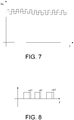
- the Fig. 7 shows the course of the signal u w provided for driving the converter 41.
- the advantage is that demodulation is simplified. A wide variety of patterns can be imprinted with the procedure presented. The amplitude of the signal assigned to the high-frequency voltage (high-frequency signal u HF ) was determined through experiments.
- the high-frequency current components of the longitudinal and transverse currents are obtained in that the measuring device 42 carries out a discrete measurement at a frequency that is twice as large as the frequency of the high-frequency signal u HF .
- the corresponding measurements are clocked in such a way that if two measurements are carried out one after the other, one of the measurements is at the maximum and the other measurement is at the Minimum of the measured currents takes place.
- the high-frequency current components of the longitudinal and transverse currents can then be determined by forming the difference between the measured corresponding currents of two consecutive measurements.
- phase currents i 1,2,3 in the 8kHz clock are measured in the case of the present embodiment.
- the phase currents i 1,2,3 are transformed into the longitudinal and transverse currents actual values i s, d, i s, q via a transformation known to those skilled in the art.
- the longitudinal and transverse currents also have high-frequency current components.
- the Fig. 9 shows the course of the longitudinal cross-flow.
- the longitudinal and transverse currents each have, for example, a high-frequency current component and a direct component. Since measurements are made with twice the controller frequency, two measurements are available for each controller cycle for the longitudinal and cross currents.
- one of the measurements is at the maximum (in each case at T1 in the Fig. 9 ) and the other measurement at the minimum (each at T2 in the Fig. 9 ) of the measured currents.
- the high-frequency current components of the longitudinal and transverse currents can then be determined by forming the difference between the measured corresponding currents of two consecutive measurements.
- the measurement made at T2 is used for current control.
- the angular position of the rotor during the braking phase can be determined on the basis of the characteristic maps of the longitudinal and transverse inductances.
- the converter 41 is also made for the converter 41 to be activated at the end of the braking phase in such a way that it moves the piston 34 away from the specific position for the standstill.
- the Fig. 10 shows an alternative structure of the field-oriented control 43, which is based on the so-called maximum torque per ampere principle.
- the longitudinal current setpoint i d, soll is not set to zero, but rather, like the cross-current setpoint i q, soll, is determined by the external speed control loop.
- the signal generated by the external speed control loop is present at the output of the controller 53 and is assigned to the torque to be applied by the three-phase synchronous motor 36.
- the structure shown has a first function block 55 and a second function block 56.
- the first function block 55 is located between the output of the controller 53 of the outer speed control loop and the formation of the difference from the cross-current setpoint i qj, soll and the cross-current actual value i s , q .
- the second function block 56 is located between the output of the controller 53 of the outer speed control loop and the formation of the difference from the longitudinal current setpoint id , soll and the actual cross-current value i d , q .
- the longitudinal current setpoint i d, soll and the cross-current setpoint i q, soll are determined, among other things, on the basis of a relationship between the series and cross inductances and on the basis of the signal determined by the external speed control loop. Since this mentioned relationship is a non-linear one, the longitudinal current nominal value i d, soll and the cross-current nominal value i q, soll are preferably determined by means of a look-up table stored in the function blocks 55, 56.
- the output signal of the first function block 55 is the cross-flow actual value i s , q and the output signal of the second function block 56 is the longitudinal actual value i s , i .
- the functions of the two function blocks 55, 56 result from the characteristic fields of the longitudinal and transverse inductances L d , L q and are stored, for example, in a look-up table.
- the Fig. 11 shows as a further example of a household appliance a household tumble dryer 101 which has a corresponding field-oriented controlled electric drive 43, the three-phase synchronous motor of which is part of a compressor 102 or is intended to drive the compressor 102.
- the compressor 102 is part of a heat pump circuit 103.
Landscapes
- Engineering & Computer Science (AREA)
- Power Engineering (AREA)
- Mechanical Engineering (AREA)
- General Engineering & Computer Science (AREA)
- Physics & Mathematics (AREA)
- Thermal Sciences (AREA)
- Computer Hardware Design (AREA)
- Control Of Ac Motors In General (AREA)
Abstract
Description
- Die Erfindung betrifft ein Verfahren zum Betreiben eines Haushaltsgerätes, das einen feldorientiert geregelten elektrischen Antrieb umfasst, und ein entsprechendes Haushaltsgerät.
- Die
DE 10 2017 211 217 A1 offenbart ein Haushaltskältegerät, das einen Kältemittelkreislauf mit einem Verdichter und einen drehzahlgeregelten elektrischen Antrieb aufweist. Die Reglung des elektrischen Antriebs ist eine feldorientierte Regelung und der elektrische Antrieb umfasst einen Umrichter und einen dem Umrichter nachgeschalteten permanenterregten Drehstromsynchronmotor, der Teil des Verdichters ist oder vorgesehen ist, den Verdichter anzutreiben. Das Haushaltkältegerät ist eingerichtet ist, den Umrichter derart anzusteuern, dass bei eingeschaltetem Verdichter die Drehzahl des Drehstromsynchronmotors aufgrund eines Ansteuerns durch den Umrichter zumindest in etwa gleich einer vorgegebenen Drehzahl ist, den Umrichter derart anzusteuern um den eingeschalteten Verdichter abzuschalten, dass sich die Drehzahl des Drehstromsynchronmotors verringert, bis die Drehzahl eine vorgegebene Minimaldrehzahl erreicht, und danach den Umrichter derart anzusteuern, dass der Drehstromsynchronmotor für wenigstens eine vorgegebene Zeitdauer abgeschaltet ist. - Die
DE 10 2008 029 910 A1 offenbart eine Haushaltsgeschirrspülmaschine, die eine Pumpe und einen feldorientiert geregelten elektrischen Antrieb aufweist. Der elektrische Antrieb umfasst einen Umrichter und einen dem Umrichter nachgeschalteten permanenterregten Drehstromsynchronmotor, der die Pumpe antreibt. - Beispielsweise aus der
DE 10 2016 210 443 A1 oder derDE 10 2017 213 069 A1 ist es bekannt, der Versorgungsspannung eines Drehstromsynchronmotors eine hochfrequente Spannung zu überlagern, welche einen entsprechenden, überlagerten hochfrequenten Anteil der Strangströme des Drehstrommotors bewirkt., um die Winkelposition des Rotors relativ zum Stator des Drehstrommotors zu bestimmen. - Aufgabe der Erfindung ist es, ein verbessertes Verfahren zum Betreiben eines Haushaltsgerätes anzugeben, das einen drehzahlgeregelten elektrischen Antrieb aufweist, dessen Reglung eine feldorientierte Regelung und dessen Motor ein permanenterregten Drehstromsynchronmotor ist, der Teil einer Komponente des Haushaltsgerätes ist oder vorgesehen ist, diese Komponente anzutreiben.
- Die Aufgabe der Erfindung wird gelöst durch ein Verfahren zum Betreiben eines Haushaltsgerätes, das eine Komponente und einen geregelten elektrischen Antrieb aufweist, der einen permanenterregten Drehstromsynchronmotor, ein insbesondere als Umrichter ausgebildetes Stellglied zum Ansteuern des Drehstromsynchronmotors und eine feldorientierte Regelung zum Ansteuern des Stellglieds aufweist, wobei der Drehstromsynchronmotor einen Stator und einen bezüglich des Stators drehbar gelagerten Rotor umfasst und Teil der Komponente ist oder vorgesehen ist, diese Komponente anzutreiben, aufweisend folgende Verfahrensschritte:
- während einer Betriebsphase des elektrischen Antriebs, drehzahlgeregeltes Betreiben des geregelten elektrischen Antriebs mittels der feldorientierte Regelung und in Abhängigkeit einer mittels der Längs- und Querströme und eines mathematischen Modells des Drehstromsynchronmotors ermittelten Winkelposition des Rotors relativ zum Stator, und
- während einer der Betriebsphase nachfolgenden Bremsphase des elektrischen Antriebs ,
- Verringern der Drehzahl des Drehstromsynchronmotors durch drehzahlgeregeltes Betreiben des geregelten elektrischen Antriebs mittels der feldorientierten Regelung und in Abhängigkeit einer mittels der Längs- und Querströme und eines mathematischen Modells des Drehstromsynchronmotors ermittelten Winkelposition des Rotors relativ zum Stator, bis die Drehzahl eine vorbestimmte Grenzdrehzahl erreicht,
- Überlagern einer von dem Stellglied erzeugten und zum Betreiben des Drehstromsynchronmotors vorgesehenen Versorgungsspannung mit einer hochfrequenten Spannung, wodurch Strangströme und die Längs- und Querströme des Drehstromsynchronmotors entsprechende hochfrequente Stromanteile aufweisen,
- Ermitteln hochfrequente Stromanteile der Längs- und Querströme,
- Ermitteln der Winkelposition des Rotors relativ zum Stator in Abhängigkeit der hochfrequenten Stromanteile der Längs- und Querströme, und
- weiteres Verringern der Drehzahl des Drehstromsynchronmotors durch drehzahlgeregeltes Betreiben des geregelten elektrischen Antriebs mittels der feldorientierten Regelung und in Abhängigkeit der mittels der hochfrequenten Stromanteile der Längs- und Querströme ermittelten Winkelposition des Rotors relativ zum Stator.
- Ein weiterer Aspekt der Erfindung betrifft ein Haushaltsgerät, aufweisend eine Komponente und einen geregelten elektrischen Antrieb, der einen permanenterregten Drehstromsynchronmotor, ein insbesondere als Umrichter ausgebildetes Stellglied zum Ansteuern des Drehstromsynchronmotors und eine feldorientierte Regelung zum Ansteuern des Stellglieds aufweist, wobei der Drehstromsynchronmotor einen Stator und einen bezüglich des Stators drehbar gelagerten Rotor umfasst und Teil der Komponente ist oder vorgesehen ist, diese Komponente anzutreiben, und das Haushaltsgerät ausgebildet ist, das erfindungsgemäße Verfahren durchzuführen.
- Ein weiterer Aspekt der Erfindung betrifft ein Haushaltsgerät, aufweisend eine Komponente und einen geregelten elektrischen Antrieb, der einen permanenterregten Drehstromsynchronmotor, ein insbesondere als Umrichter ausgebildetes Stellglied zum Ansteuern des Drehstromsynchronmotors und eine feldorientierte Regelung zum Ansteuern des Stellglieds aufweist, wobei der Drehstromsynchronmotor einen Stator und einen bezüglich des Stators drehbar gelagerten Rotor umfasst und Teil der Komponente ist oder vorgesehen ist, diese Komponente anzutreiben, und das Haushaltsgerät ausgebildet ist, während einer Anlaufphase des elektrischen Antriebs,
während einer Betriebsphase des elektrischen Antriebs, den geregelten elektrischen Antriebs mittels der feldorientierte Regelung und in Abhängigkeit einer mittels der Längs-und Querströme und eines mathematischen Modells des Drehstromsynchronmotors ermittelten Winkelposition des Rotors relativ zum Stator drehzahlgeregelt zu betreiben, und
während einer der Betriebsphase nachfolgenden Bremsphase des elektrischen Antriebs, - die Drehzahl des Drehstromsynchronmotors durch drehzahlgeregeltes Betreiben des geregelten elektrischen Antriebs mittels der feldorientierten Regelung und in Abhängigkeit einer mittels der Längs- und Querströme und eines mathematischen Modells des Drehstromsynchronmotors ermittelten Winkelposition des Rotors relativ zum Stator zu verringern, bis die Drehzahl eine vorbestimmte Grenzdrehzahl erreicht,
- eine von dem Stellglied erzeugten und zum Betreiben des Drehstromsynchronmotors vorgesehenen Versorgungsspannung mit einer hochfrequenten Spannung zu überlagern, wodurch Strangströme und somit die , Längs- und Querströme des Drehstromsynchronmotors entsprechende hochfrequente Stromanteile aufweisen
- die hochfrequenten Stromanteile der Längs- und Querströme zu ermitteln,
- die Winkelposition des Rotors relativ zum Stator in Abhängigkeit der hochfrequenten Stromanteile der Längs- und Querströme zu ermitteln, und
- die Drehzahl des Drehstromsynchronmotors durch drehzahlgeregeltes Betreiben des geregelten elektrischen Antriebs mittels der feldorientierten Regelung und in Abhängigkeit der mittels der hochfrequenten Stromanteile der Längs- und Querströme ermittelten Winkelposition des Rotors relativ zum Stator zu verringern.
- Das Haushaltsgerät umfasst den geregelten elektrischen Antrieb, dessen Motor ein permanent erregter Drehstromsynchronmotor ist. Der permanenterregte Drehstromsynchronmotor ist z.B. ein bürstenloser Gleichstrommotor.
- Der elektrische Antrieb umfasst außerdem das Stellglied, welches den Drehstromsynchronmotor ansteuert, d.h. den Drehstromsynchronmotor mit der Versorgungsspannung versorgt. Die Versorgungsspannung ist eine dreiphasige Spannung, deren Grundfrequenz durch die Drehzahlregelung und der gewünschten Soll-Drehzahl eingestellt wird.
- Das Stellglied ist insbesondere ein Umrichter, der vorzugsweise mittels pulsweiten Modulation betrieben wird.
- Die Regelung des geregelten elektrischen Antriebs steuert das Stellglied bzw. den Umrichter an und ist eine feldorientierte Regelung. Eine feldorientierte Regelung bildet üblicherweise eine Kaskadenstruktur mit innenliegenden Stromregelkreisen, denen ein äußerer Drehzahlregelkreis überlagert ist. Die feldorientierte Regelung umfasst somit insbesondere eine Kaskadenstruktur mit einem einen Stromregler aufweisenden innenliegenden Stromregelkreis, dem ein äußerer Drehzahlregelkreis überlagert ist. Der Stromregler ist insbesondere ein PI-Regler, also vorzugsweise ein Regler mit einem Proportional- und einem Integralanteil.
- Die feldorientierte Regelung ist vorzugsweise eine diskrete bzw. digitale feldorientierte Regelung. Die Takt- bzw. Regelfrequenz der diskreten bzw. digitalen feldorientierten Regelung und somit des Stromreglers ist vorzugsweise größer als 1kHz, z.B. 4kHz.
- Für die feldorientierte Regelung ist es nötig, die Winkelposition des Rotors relativ zum Stator des Drehstromsynchronmotors zu kennen. Um die Winkelposition sensorlos bzw. ohne einen Geber zu ermitteln, kann die Winkelposition in Abhängigkeit der sogenannten und dem Fachmann im Prinzip bekannten Längs- und Querströme, die aus den Strangströmen des Drehstromsynchronmotor berechnet werden können, und einem mathematischen Modells des Drehstromsynchronmotors, das auch als Beobachter bezeichnet wird, ermitteln. Die Winkelposition des Rotors relativ zum Stator wird somit insbesondere sensorlos ermittelt.
- Bei einer relativ geringen Drehzahl des Drehstromsynchronmotors kann es jedoch sein, dass ein Auswerten dieser Ströme kein zuverlässiges Ermitteln der Winkelposition des Rotors ermöglicht. Deshalb wird erfindungsgemäß während der Bremsphase des elektrischen Antriebs insbesondere bis zum Stillstand die von dem Stellglied erzeugte und zum Betreiben des Drehstromsynchronmotors vorgesehene Versorgungsspannung vorzugsweise erst ab dem Erreichen der Grenzdrehzahl mit der hochfrequenten Spannung überlagert, wodurch die Strangströme des Drehstromsynchronmotors entsprechende hochfrequente Stromanteile aufweisen. Dies wird im Englischen als "high frequncy injection (HFI)" bezeichnet. Dadurch weisen die Längs- und Querströme entsprechende hochfrequente Stromanteile auf. Aufgrund dieser hochfrequenten Stromanteile ist es dann möglich, auch bei relativ niedrigen Drehzahlen eine für die feldorientierte Regelung nötige Winkelposition des Rotors sensorlos zu ermitteln, und somit während der Bremsphase die Drehzahl des Drehstromsynchronmotors durch drehzahlgeregeltes Betreiben des geregelten elektrischen Antriebs mittels der feldorientierten Regelung und in Abhängigkeit der mittels der hochfrequenten Stromanteile der Längs- und Querströme ermittelten Winkelposition des Rotors relativ zum Stator zu erniedrigen, bis der Drehstromsynchronmotor gestoppt ist.
- Aufgrund dieser hochfrequenten Stromanteile ist es ggf. sogar möglich, beim Stillstand des Drehstromsynchronmotors die Winkelposition des Rotors sensorlos zu ermitteln.
- Die Grenzdrehzahl liegt vorzugsweise zwischen 600 und 1400 Umdrehungen pro Minute, insbesondere um 1000 Umdrehungen pro Minute.
- Die hochfrequente Spannung und somit die hochfrequenten Stromanteile weisen vorzugsweise eine Frequenz von größer als 1 kHz, vorzugsweise von größer als 2 kHz auf.
- Während der der Bremsphase vorhergehenden Betriebsphase wird der geregelte elektrische Antrieb drehzahlgeregelt mittels der feldorientierten Regelung und in Abhängigkeit einer mittels der Längs- und Querströme und des mathematischen Modells des Drehstromsynchronmotors ermittelten Winkelposition des Rotors relativ zum Stator betrieben, d.h. die Winkelposition des Rotors wird während der Betriebsphase in Abhängigkeit der den Drehstromsynchronmotor antreibenden Längs- und Querströme und des mathematischen Modells des Drehstromsynchronmotors ermittelt.
- Vorzugsweise wird die vom Stellglied erzeugte und zum Betreiben des Drehstromsynchronmotors vorgesehene Versorgungsspannung lediglich nach dem Erreichen der Grenzfrequenz mit der hochfrequenten Spannung überlagert, d.h. vorzugsweise wird das Stellglied während der Betriebsphase und dem Teil der Bremsphase bis zum Erreichen der Grenzfrequenz ohne der überlagerten hochfrequenten Spannung betrieben. Dies kann sich positiv auf den Energieverbrauch des elektrischen Antriebs und somit des Haushaltsgerätes auswirken.
- Nach einer bevorzugten Ausführungsform des erfindungsgemäßen Verfahrens umfasst dieses ein Erzeugen eines Ansteuersignals für das Stellglied durch Überlagern des vom Stromregler erzeugten, der Versorgungspannung zugeordneten Signals mit einem der hochfrequenten Spannung zugeordneten Signal. Das erfindungsgemäße Haushaltsgerät ist somit vorzugsweise eingerichtet, ein Ansteuersignal für das Stellglied zu erzeugen, durch ein Überlagern eines vom Stromregler erzeugten, der Versorgungsspannung zugeordneten Signals mit einem der hochfrequenten Spannung zugeordneten Signal. Diese beiden Signale können in relativ einfacher weise addiert werden, wodurch in relativ einfacher weise das Steuerglied aufgrund des Ansteuersignals die mit der hochfrequenten Spannung überlagerte Versorgungsspannung für den Drehstromsynchronmotor erzeugen kann.
- Bei der feldorientierten Regelung werden die Strangströme des Drehstrommotors in Längs- und Querströme transformiert. Die Längs- und Querströme werden für den Stromregekreis verwendet, um daraus ein der Versorgungsspannung zugeordnetes Signal zum Ansteuern des Stellglieds zu erhalten. Dem Längsstrom und dem Querstrom sind jeweils ein Stromregler zugeordnet. Vorzugsweise wird das der hochfrequenten Spannung zugeordnete Signal lediglich dem von dem Längsstrom zugeordneten Stromregler erzeugten Signals überlagert.
- Bei der feldorientierten Regelung kann es vorgesehen sein, dass der Soll-Wert des Längsstroms gleich Null ist. Vorzugsweise ist die feldorientierte Regelung nach dem sogenannten maximum torque per ampere Prinzip, um insbesondere bei unterschiedlich großen Längs- und Querinduktivitäten des Drehstromsynchronmotors den Energieverbrauch des elektrischen Antriebs und somit des Haushaltsgerätes zu verringern. In diesem Fall wird nicht der Sollwert des Längsstroms zu Null oder auf einen festen Wert gesetzt, sondern u.a. aufgrund einer Beziehung zwischen den Längs- und Querinduktivitäten und aufgrund des vom äußeren Drehzahlregelkreises ermittelten Signals, das dem vom Drehstromsynchronmotor aufzubringenden Drehmoment zugeordnet ist, ermittelt. Da diese genannte Beziehung eine nichtlineare ist, werden die Sollwerte des Längs- und des Querstroms vorzugsweise in einer Look-up Tabelle hinterlegt.
- Das der hochfrequenten Spannung zugeordnete Signal kann z.B. sinusförmig sein. Vorzugsweise ist es rechteckförmig.
- Im Falle der diskreten feldorientierten Regelung wird vorzugsweise der Stromregler mit einer Reglerfrequenz betrieben, die gleich der Frequenz der hochfrequenten Spannung bzw. des der hochfrequenten Spannung zugeordneten Signals ist. Insbesondere kann es auch vorgesehen sein, dass die Frequenz der hochfrequenten Spannung bzw. des der hochfrequenten Spannung zugeordneten Signals ein ganzzahliges Vielfaches der Reglerfrequenz ist.
- Um die hochfrequenten Stromanteile der Längs- und Querströme in relativ einfacher weise zu erhalten, weist das erfindungsgemäße Verfahren gemäß einer bevorzugten Variante ein diskretes Messen der Längs- und Querströme zumindest während der Anlaufphase mit der doppelten Frequenz der Frequenz der hochfrequenten Spannung auf, wobei die Messungen derart getaktet sind, dass bei zwei hintereinander erfolgten Messungen eine der Messungen beim Maximum und die andere Messung beim Minimum der gemessenen Ströme erfolgen. Das erfindungsgemäße Haushaltsgerät ist somit gemäß einer bevorzugten Ausführung derart ausgebildet, dass es die Längs- und Querströme zumindest während der Anlaufphase mit der doppelten Frequenz der Frequenz der hochfrequenten Spannung misst, wobei die Messungen derart getaktet sind, dass bei zwei hintereinander erfolgten Messungen eine der Messungen beim Maximum und die andere Messung beim Minimum der gemessenen Ströme erfolgen. Dann können die hochfrequenten Stromanteile der Längs- und Querströme durch Differenzbilden der gemessenen entsprechenden Ströme zweier hintereinander folgender Messungen ermittelt werden.
- Das Haushaltsgerät ist z.B. eine Haushaltswaschmaschine mit einer drehbar gelagerten Wäschetrommel als die vom elektrischen Antrieb angetriebene Komponente.
- Das Haushaltsgerät ist z.B. eine Haushaltsgeschirrspülmaschine mit einer Laugenpumpe als der Komponente.
- Vorzugsweise ist die Komponente ein Verdichter, der eine Verdichterkammer umfasst und zum Verdichten eines Fluids vorgesehen ist.
- Ein Beispiel eines Haushaltsgerätes mit einem Verdichter, ist ein Haushaltswäschetrockner, der einen den Verdichter umfassenden Wärmepumpenkreislauf und den geregelten elektrischen Antrieb umfasst.
- Ein weiteres Beispiel eines Haushaltsgerätes mit einem Verdichter ist ein Haushaltskältegerät, das einen wärmeisolierten Korpus mit einem kühlbaren Innenbehälter, der einen zum Lagern von Lebensmitteln vorgesehenen kühlbaren Innenraum begrenzt, einen zum Kühlen des kühlbaren Innenraums vorgesehenen Kältemittelkreislauf mit einem Kühlmittel als das Fluid und dem Verdichter, und den geregelten elektrischen Antrieb umfasst.
- Das als Haushaltskältegerät umfasst den wärmeisolierten Korpus mit dem Innenbehälter, der den kühlbaren Innenraum begrenzt. Der kühlbare Innenraum ist zum Lagern von Lebensmitteln vorgesehen und wird mittels des Kältemittelkreislaufs gekühlt.
- Der kühlbare Innenraum kann vorzugsweise mittels eines Türblatts verschlossen werden. Das Türblatt ist vorzugsweise bezüglich einer Achse, die vorzugsweise vertikal verläuft, schwenkbar gelagert. Im geöffneten Zustand ist der kühlbare Innenraum zugänglich.
- Der Kältemittelkreislauf als solcher ist dem Fachmann im Prinzip bekannt und umfasst den Verdichter und insbesondere einen dem Verdichter nachgeschalteten Verflüssiger, eine dem Verflüssiger nachgeschaltete Drosselvorrichtung und einen Verdampfer, der zwischen der Drosselvorrichtung und dem Verdichter angeordnet ist.
- Vorzugsweise umfasst die Verdichterkammer des Verdichters einen Einlass und einen Auslass, einen innerhalb der Verdichterkammer verschieblich gelagerten Kolben und eine Kurbelwelle. In diesem Fall ist der Rotor des Drehstromsynchronmotors über die Kurbelwelle mit dem Kolben gekoppelt, sodass im Betrieb des Verdichters der Kolben mittels des Drehstromsynchronmotors ein von der Verdichterkammer und dem Kolben eingeschlossenes Volumen zum Verdichten des Fluids zu verkleinern vermag, wobei in einer bestimmten Position des Kolbens relativ zur Verdichterkammer das Volumen minimal und in einer weiteren bestimmten Position des Kolbens relativ zur Verdichterkammer das Volumen maximal ist. Ein solcher Verdichter wird üblicherweise als Hubkolben-Verdichter bezeichnet. Bevorzugt kann dann das Stellglied zum Ende der Bremsphase derart angesteuert werden, dass dieser für den Stillstand des Drehstromsynchronmotors weg von der bestimmten Position zum Stillstand kommt.
- Im Betrieb des Verdichters und im Falle des Haushaltskältegerätes wird der Drehstromsynchronmotor insbesondere mit einer z.B. von einer elektronischen Steuervorrichtung oder einer Temperaturregelung des Haushaltskältegerätes ermittelten bzw. vorgegebenen Drehzahl betrieben.
- Hubkolben-Verdichter weisen eine charakteristische Drehmomentkurve auf. Diese kann in Abhängigkeit vom Lastpunkt, aber auch von der Drehzahl des Drehstromsynchronmotors abhängen. Auch mechanische Gegebenheiten des Verdichters, wie z.B. ein Trägheitsmoment rotierenden Bestandteile des Verdichters können, eine Auswirkung auf den Betrieb des Drehstromsynchronmotors haben.
- In einer bestimmten Position des Kolbens relativ zur Verdichterkammer ist das Volumen minimal. Diese bestimmte Position wird üblicherweise als oberer Totpunkt bezeichnet.
- In einer weiteren bestimmten Position des Kolbens relativ zur Verdichterkammer ist das Volumen maximal. Diese weitere bestimmte Position wird üblicherweise als unterer Totpunkt bezeichnet.
- Bewegt der Drehstromsynchronmotor den Kolben von seiner bestimmten Position, d.h. von seinem oberen Totpunkt, in seine weitere bestimmte Position, d.h. in seinen unteren Totpunkt, so erhöht sich das Volumen und der Verdichter saugt das Fluid durch seinen Einlass ein.
- Bewegt der Drehstromsynchronmotor den Kolben von seiner weiteren bestimmten Position, d.h. von seinem unteren Totpunkt, in seine bestimmte Position, d.h. in seinen oberen Totpunkt, so verringert sich das Volumen und der Verdichter verdichtet das in der Verdichterkammer befindliche Fluid, bis sich der Auslass am oberen Totpunkt öffnet, damit das verdichtete Fluid zum Verflüssiger gelangen kann.
- Ausführungsbeispiele der Erfindung sind exemplarisch in den beigefügten schematischen Zeichnungen dargestellt. Es zeigen:
- Fig. 1
- ein Haushaltskältegerät in einer perspektivischen Darstellung,
- Fig. 2
- einen, einen Verdichter aufweisenden Kältemittelkreislauf des Haushaltskältegerätes,
- Fig. 3
- den Verdichter,
- Fig. 4
- einen feldorientiert geregelten elektrischen Antrieb des Haushaltskältegerätes,
- Fig. 5
- die Struktur der feldorientierten Regelung des feldorientiert geregelten elektrischen Antriebs,
- Fig. 6
- ein hochfrequentes Signal,
- Fig. 7
- ein Ansteuersignal für einen Umrichter des feldorientiert geregelten elektrischen Antrieb,
- Fig. 8
- einen Duty-Cycle,
- Fig. 9
- einen Längsstrom, der einen hochfrequenten Stromanteil umfasst,
- Fig. 10
- eine alternative Struktur der feldorientierten Regelung, und
- Fig. 11
- einen Haushaltswäschetrockner.
- Die
Fig. 1 zeigt in einer perspektivischen Darstellung ein Haushaltskältegerät 1 als Beispiel eines Haushaltsgerätes, das eine Komponente und einen geregelten elektrischen Antrieb aufweist, der einen permanenterregten Drehstromsynchronmotor, ein insbesondere als Umrichter ausgebildetes Stellglied zum Ansteuern des Drehstromsynchronmotors und eine feldorientierte Regelung zum Ansteuern des Stellglieds aufweist, wobei der Drehstromsynchronmotor einen Stator und einen bezüglich des Stators drehbar gelagerten Rotor umfasst und Teil der Komponente ist oder vorgesehen, diese Komponente anzutreiben. - Das Haushaltskältegerät 1 umfasst insbesondere einen wärmeisolierten Korpus 10 mit einem Innenbehälter 2, der einen kühlbaren Innenraum 3 begrenzt. Der kühlbare Innenraum 3 ist zum Lagern von nicht näher dargestellten Lebensmitteln vorgesehen.
- Das Haushaltskältegerät 1 weist im Falle des vorliegenden Ausführungsbeispiels ein schwenkbares Türblatt 4 zum Verschließen des kühlbaren Innenraums 3 auf. Das Türblatt 4 ist insbesondere bezüglich einer vertikal verlaufenden Achse schwenkbar gelagert. Bei geöffnetem Türblatt 4, wie in der
Fig. 1 dargestellt, ist der kühlbare Innenraum 3 zugänglich. - An der in Richtung kühlbaren Innenraum 3 gerichteten Seite des Türblatts 4 sind im Falle des vorliegenden Ausführungsbeispiels mehrere Türabsteller 5 zum Lagern von Lebensmitteln angeordnet. Im kühlbaren Innenraum 3 sind insbesondere mehrere Fachböden 6 zum Lagern von Lebensmitteln angeordnet und im unteren Bereich des kühlbaren Innenraums 3 ist insbesondere eine Schublade 7 angeordnet, in der ebenfalls Lebensmittel gelagert werden können.
- Das Haushaltskältegerät 1 umfasst einen in der
Fig. 2 gezeigten Kältemittelkreislauf 20 zum Kühlen des kühlbaren Innenraums 3. Im Falle des vorliegenden Ausführungsbeispiels umfasst der Kältemittelkreislauf 20 ein nicht näher dargestelltes, dem Fachmann im Prinzip jedoch bekanntes Kältemittel, einen Verdichter 21, einen dem Verdichter 21 nachgeschalteten Verflüssiger 22, eine dem Verflüssiger 22 nachgeschaltete Drosselvorrichtung 23, die insbesondere als ein Drossel- oder Kapillarrohr ausgeführt ist, und einen Verdampfer 24, der zwischen der Drosselvorrichtung 23 und dem Verdichter 21 angeordnet ist. Der Verdichter 21 ist vorzugsweise innerhalb eines Maschineraums des Haushaltkältegerätes 1 angeordnet, der sich insbesondere hinter der Schublade 7 befindet. - Der Verdichter 21 ist als ein Hubkolbenverdichter ausgeführt und in der
Fig. 3 näher dargestellt. - Der Verdichter 21 umfasst eine Verdichterkammer 31 mit einem Einlass 32 und mit einem Auslass 33 für das Kältemittel, und einen innerhalb der Verdichterkammer 31 verschieblich gelagerten Kolben 34. Der Einlass 33 und der Auslass 33 sind jeweils mit entsprechenden Ventilen versehen, wie dies dem Fachmann im Prinzip bekannt ist.
- Der Verdichter 21 umfasst eine Kurbelwelle 35 und einen Drehstromsynchronmotor 36. Der Verdichter 21 ist ein Beispiel der obenstehend genannten Komponente.
- Der Drehstromsynchronmotor 36 ist insbesondere ein permanenterregter Drehstromsynchronmotor, vorzugsweise ein bürstenloser Gleichstrommotor, und umfasst einen Stator 37 und einen relativ zum Stator 37 drehbar gelagerten Rotor 38. Eines der Enden der Kurbelwelle 35 ist mit dem Kolben 34 und das andere Ende der Kurbelwelle 35 ist mit dem Rotor 38 des Drehstromsynchronmotors 36 gekoppelt, sodass im bestimmungsgemäßen Betrieb des Haushalskältegerätes 1 bzw. des Verdichters 21 der Kolben 34 mittels des Drehstromsynchronmotors 36 ein von der Verdichterkammer 31 und dem Kolben 34 eingeschlossenes Volumen 39 zum Verdichten des Kühlmittels zu verkleinern vermag.
- Das Haushaltskältegerät 1 umfasst im Falle des vorliegenden Ausführungsbeispiels eine elektronische Steuervorrichtung 8, die eingerichtet ist, den Kältemittelkreislauf 20, insbesondere den Verdichter 21 des Kältemittelkreislaufs 20 derart anzusteuern, dass der kühlbare Innenraum 3 zumindest in etwa eine vorgegebene oder vorgebbare Soll-Temperatur aufweist. Die elektronische Steuervorrichtung 8 ist vorzugsweise derart eingerichtet, dass sie die Temperatur des kühlbaren Innenraums 3 regelt. Um gegebenenfalls die Ist-Temperatur des kühlbaren Innenraums 3 zu erhalten, kann das Haushaltskältegerät 1 wenigstens einen nicht näher dargestellten und mit der elektronischen Steuervorrichtung 8 verbundenen Temperatursensor aufweisen.
- Um den Kältemittelkreislauf 20 anzusteuern bzw. zu regeln, umfasst das Haushaltskältegerät 1 im Falle des vorliegenden Ausführungsbeispiels einen in der
Fig. 4 gezeigten feldorientiert geregelten elektrischen Antrieb 40, welcher den Drehstromsynchronmotor 36 des Verdichters 21 aufweist. Bei Bedarf wird der Drehstromsynchronmotor 36 entsprechend einer von der elektronischen Steuervorrichtung 8 vorgegebenen Soll-Drehzahl nsoll angetrieben. Die Soll-Drehzahl nsoll wird insbesondere von der elektronischen Steuervorrichtung 8 aufgrund einer beabsichtigten Kühlung des kühlbaren Innenraums 3 berechnet bzw. vorgegeben, beispielsweise aufgrund der aktuellen Temperatur und der Soll-Temperatur des kühlbaren Innenraums 3. - Insbesondere weist der Drehstromsynchronmotor 36 eine Längsinduktivität Ld und eine Querinduktivität Lq auf, die sich im Falle des vorliegenden Ausführungsbeispiels unterscheiden. Im Falle des vorliegenden Ausführungsbeispielswurden die Kennfelder für die Längsinduktivität Ld und die Querinduktivität Lq vermessen
- Der elektrische Antrieb 40 umfasst ein Stellglied zum Antreiben des Drehstromsynchronmotors 36. Das Stellglied ist als Umrichter 41 ausgeführt und erzeugt im Betrieb des elektrischen Antriebs 40 eine dreiphasige Versorgungsspannung, deren Grundschwingung eine Amplitude und eine Grundfrequenz f aufweist, die indirekt abhängig von der Soll-Drehzahl nsoll und einer Ist-Drehzahl nist des Drehstromsynchronmotors 36 ist.
- Im Falle des vorliegenden Ausführungsbeispiels weist der feldorientiert geregelte elektrische Antrieb 40 eine Messvorrichtung 42 auf, mittels derer die elektrischen Strangströme i1,2,3 des Drehstromsynchronmotors 36 gemessen werden und die Ist-Drehzahl des Drehstromsynchronmotors 36 sensorlos ermittelt wird. Die Messvorrichtung 42 ist auch vorgesehen, aus den Strangströme i1,2,3 transformierte Quer- und Längsströme iq, id zu errechnen, wie dies dem Fachmann im Prinzip geläufig ist. Aus den Quer- und Längsströme iq, id und einem mathematischen Modell des Drehstrommotors 36 kann die Ist-Drehzahl nist des Drehstromsynchronmotors 36 errechnet werden, wie es dem Fachmann im Prinzip geläufig ist.
- Im Falle des vorliegenden Ausführungsbeispiels weist der feldorientiert geregelte elektrische Antrieb 40 eine feldorientierte Regelung 43 auf, die den Umrichter 41 ansteuert.
- Die feldorientierte Regelung 43 bildet eine Kaskadenstruktur mit innenliegenden Stromregelkreisen, denen ein äußerer Drehzahlregelkreis überlagert ist, wie dies dem Fachmann im Prinzip geläufig ist. Die
Fig. 5 zeigt teilweise diese Struktur. - Für die feldorientierte Regelung ergibt sich eine Regelstruktur, bei der die transformierten Quer- und Längsströme iq, id mittels der Stromregelkreise geregelt werden. Im Falle des vorliegenden Ausführungsbeispiels umfassen die Stromregelkreise vorzugsweise einen ersten Stromregler 51 für den Querstrom iq und einen zweiten Stromregler 52 für den Längsstrom id. Die beiden Stromregler 51, 52 sind insbesondere PI-Regler.
- Die feldorientierte Regelung 43 bzw. die Messvorrichtung 42 ist im Falle des vorliegenden Ausführungsbeispiels derart ausgeführt, dass sie die Strangströme i1,2,3 des Drehstromsynchronmotors 36 in auf den Rotor des Drehstromsynchronmotors 36 bezogene rotorfeste Längs- und Querstrom-Ist-Werte is,d, is,q transformiert. Die Abweichung zwischen dem Sollwert iq,soll des Querstroms iq und dem Querstroms-Ist-Wert is,q ist das Eingangssignal für den ersten Stromregler 51, und die Abweichung zwischen dem Längsstrom-Sollwert id,soll und dem Längsstrom-Ist-Wert is,d ist das Eingangssignal für den zweiten Stromregler 52.
- Die Ausgangssignale uq, ud der beiden Stromregler 51, 52 entsprechen transformierten elektrischen Spannungen, welche mittels einer dem Fachmann im Prinzip bekannten Transformation 54 in zum Ansteuern des Umrichters 41 geeignete Signale uw transformiert werden.
- Der Querstrom-Sollwert iq,soll ergibt sich im Falle des vorliegenden Ausführungsbeispiels aufgrund dieses äußeren Drehzahlregelkreises, welcher einen Regler 53 aufweist und welcher abhängig von der Soll-Drehzahl nsoll und der Ist-Drehzahl nist berechnet wird. Der Regler 53 ist insbesondere ein PI-Regler.
- Im Falle des vorliegenden Ausführungsbeispiels ist der Längsstrom-Sollwert id,soll gleich Null.
- Die feldorientierte Regelung 43 ist im Falle des vorliegenden Ausführungsbeispiels vorzugsweise eine diskrete bzw. digitale feldorientierte Regelung 43. Die Takt- bzw. Regelfrequenz der diskreten bzw. digitalen feldorientierten Regelung 43 und somit der beiden Stromregler 51, 52 ist beispielsweise 4kHz.
- Für die feldorientierte Regelung 43 ist es nötig, die Winkelposition des Rotors 38 relativ zum Stator 37 des Drehstromsynchronmotors 36 zu kennen. Die Winkelposition wird sensorlos bzw. ohne einen Geber ermittelt.
- Während einer Betriebsphase wird der feldorientierte geregelte elektrische Antrieb 40 drehzahlgeregelt mittels der feldorientierten Regelung 43 und in Abhängigkeit einer mittels der Längs- und Querströme Ist-Werte is,d, is,q und des mathematischen Modells ermittelten Winkelposition des Rotors relativ zum Stator betrieben. Während der Betriebsphase beträgt die Drehzahl des Drehstromsynchronmotors 36 z.B. mehr als 1000 Umdrehungen pro Minute.
- Im Falle des vorliegenden Ausführungsbeispiels wird während einer der Betriebsphase nachfolgenden Bremsphase des Verdichters 21 zunächst die Drehzahl des Drehstromsynchronmotors 36 durch drehzahlgeregeltes Betreiben des geregelten elektrischen Antriebs 40 mittels der feldorientierten Regelung 43 und in Abhängigkeit einer mittels der Längs- und Querströme und des mathematischen Modells des Drehstromsynchronmotors 36 ermittelten Winkelposition des Rotors 38 relativ zum Stator 37 verringert, bis die Drehzahl eine vorbestimmte Grenzdrehzahl erreicht. Die Grenzdrehzahl ist kleiner als die Drehzahl während der Betriebsphase und beträgt z.B. 1000 Umdrehungen pro Minute.
- Bei Erreichen der Grenzdrehzahl wird das Ausgangssignal ud des zweiten Stromreglers 52 mit einem hochfrequenten Signal uHF überlagert, woraus ein Signal u'd entsteht, sodass während der restlichen Bremsphase des Verdichters das zum Ansteuern des Umrichters 41 vorgesehene Signal uw ebenfalls eine Information über das hochfrequente Signal uHF aufweist. Dadurch weist die für den Drehstromsynchronmotor 36 vorgesehenen Versorgungsspannung ebenfalls einen hochfrequenten Spannungsanteil auf, wodurch die Strangströme i1,2,3 und die Längs- und Querstrom-Ist-Werte is,d, is,q entsprechende hochfrequente Stromanteile aufweisen.
- Während der Betriebsphase wird der Versorgungsspannung kein hochfrequenter Anteil überlagert.
- Während der Bremsphase des feldorientiert geregelten elektrischen Antriebs 40 insbesondere bis zum Stillstand weisen die Längs- und Querströme Ist-Werte is,d, is,q die hochfrequenten Stromanteile auf. Aufgrund dieser hochfrequenten Stromanteile ist es dann möglich, auch bei relativ niedrigen Drehzahlen eine für die feldorientierte Regelung nötige Winkelposition des Rotors 38 zu ermitteln, und somit während der Bremsphase die Drehzahl des Drehstromsynchronmotors 36 durch drehzahlgeregeltes Betreiben des geregelten elektrischen Antriebs 43 mittels der feldorientierten Regelung 43 und in Abhängigkeit der mittels der hochfrequenten Stromanteile der Längs- und Querströme Ist-Werte is,d, is,q ermittelten Winkelposition des Rotors 38 relativ zum Stator 37 bis zum Stillstand zu verringern.
- Im Falle des vorläufigen Ausführungsbeispiels ist das der hochfrequenten Spannung zugeordnete Signal (hochfrequente Signal uHF) rechteckförmig und weist eine Frequenz gleich der Reglerfrequenz der feldorientierten Regelung 43 auf, ist also im Falle des vorliegenden Ausführungsbeispiels 4kHz.
- Die beiden Stromregler 51, 52 laufen u.a. in einem Takt, der der Reglerfrequenz von insbesondere 4kHz zugeordnet ist. Der Verlauf des rechteckförmige hochfrequenten Signals uHF ist in der
Fig. 6 gezeigt und weist insbesondere eine Spannung von ± 10 V auf. - Das pulsweitenmodulierte Signal für den Umrichter 41 läuft z.B. in einem Takt entsprechend 8 kHz.
- Insbesondere wird das der hochfrequenten Spannung zugeordnete Signal (hochfrequentes Signal uHF) abwechselnd auf das Ausgangssignal ud des zweiten Stromreglers 52 addiert und subtrahiert. Die
Fig. 7 zeigt den Verlauf des zum Ansteuern des Umrichters 41 vorgesehenen Signal uw. Der Vorteil liegt darin, dass die Demodulation damit vereinfacht wird. Bei dem vorgestellten Vorgehen können die unterschiedlichsten Muster eingeprägt werden. Die Amplitude des der hochfrequenten Spannung zugeordneten Signals (hochfrequentes Signal uHF) wurde durch Versuche ermittelt. - Wird dieses Muster in den Duty-Cycle umgerechnet, ergibt sich eine Änderung der Duty-Cycle Längen entsprechend der
Fig. 8 . Je nachdem, ob durch die hochfrequente Überlagerung das Muster positiv oder negativ geändert wurde, wird der Duty-Cyle um ein ΔT verlängert oder verkürzt. Die Stromregler "sehen" davon nichts, da der Mittelwert identisch ist (bezogen auf 4kHz). - Im Falle des vorläufigen Ausführungsbeispiels werden die hochfrequenten Stromanteile der Längs- und Querströme erhalten, indem die Messvorrichtung 42 ein diskrete Messung mit einer Frequenz durchführt, die doppelt so groß ist wie die Frequenz des hochfrequenten Signals uHF.
- Die entsprechende Messungen sind derart getaktet, dass bei zwei hintereinander erfolgten Messungen eine der Messungen beim Maximum und die andere Messung beim Minimum der gemessenen Ströme erfolgt. Dann können die hochfrequenten Stromanteile der Längs- und Querströme durch Differenzbilden der gemessenen entsprechenden Ströme zweier hintereinander folgender Messungen ermittelt werden.
- Insbesondere werden im Falle des vorliegenden Ausführungsbeispiels die Strangströme i1,2,3 im 8kHz-Takt gemessen. Die Strangströme i1,2,3 werden über eine dem Fachmann bekannte Transformation nach in die Längs- und Querströme Ist-Werte is,d, is,q transformiert. Die Längs- und Querströme weisen ebenfalls hochfrequente Stromanteile auf. Die
Fig. 9 zeigt den Verlauf des Längsquerstroms. - Die Längs- und Querströme weisen z.B. jeweils einen hochfrequenten Stromanteil und einen Gleichanteil auf. Da mit doppelter Reglerfrequenz gemessen wird, liegen pro Reglertakt für die Längs- und Querströme jeweils zwei Messungen vor.
- Wie bereits erläutert, gilt bei zwei hintereinander erfolgten Messungen, dass eine der Messungen beim Maximum (jeweils bei T1 in der
Fig. 9 ) und die andere Messung beim Minimum (jeweils bei T2 in derFig. 9 ) der gemessenen Ströme erfolgt. Dann können die hochfrequenten Stromanteile der Längs- und Querströme durch Differenzbilden der gemessenen entsprechenden Ströme zweier hintereinander folgender Messungen ermittelt werden. Die bei T2 erfolgte Messung wird für die Stromregelung verwendet. Aufgrund der Kennfelder der Längs- und Querinduktivitäten kann dadurch die Winkelposition des Rotors während der Bremsphase ermittelt werden. - Im Falle des vorliegenden Ausführungsbeispiels ist es noch vorgesehen, den Umrichter 41 am Ende der Bremsphase derart anzusteuern, dass dieser für den Stillstand den Kolben 34 weg von der bestimmten Position bewegt.
- Die
Fig. 10 zeigt eine alternative Struktur des feldorientierten Regelung 43, die auf dem sogenannten maximum torque per ampere Prinzip beruht. Bei diesem Prinzip wird der Längsstrom-Sollwert id,soll nicht auf Null gesetzt, sondern wie der Querstrom-Sollwert iq,soll durch den äußeren Drehzahlregelkreis bestimmt. Das von äußeren Drehzahlregelkreis erzeugte Signal liegt am Ausgang de Reglers 53 an und ist dem von Drehstromsynchronmotor 36 aufzubringenden Drehmoment zugeordnet. - Zusätzlich weist die in der
Fig. 10 gezeigte Struktur einen ersten Funktionsblock 55 und einen zweiten Funktionsblock 56 auf. Der erste Funktionsblock 55 befindet sich zwischen dem Ausgang des Reglers 53 des äußeren Drehzahlregelkreises und der Differenzbildung aus dem Querstrom-Sollwert iqj,soll und des Querstrom-Ist-Werts is,q. Der zweite Funktionsblock 56 befindet sich zwischen dem Ausgang des Reglers 53 des äußeren Drehzahlregelkreises und der Differenzbildung aus dem Längsstrom-Sollwert id,soll und des Querstrom-Ist-Werts id,q. - Der Längsstrom-Sollwert id,soll und der Querstrom-Sollwert iq,soll werden u.a. aufgrund einer Beziehung zwischen den Längs- und Querinduktivitäten und aufgrund des vom äußeren Drehzahlregelkreises ermittelten Signals ermittelt. Da diese genannte Beziehung eine nichtlineare ist, werden der Längsstrom-Sollwert id,soll und der Querstrom-Sollwert iq,soll vorzugsweise mittels einer in den Funktionsblöcken 55, 56 hinterlegten Look-up Tabelle ermittelt.
- Somit ist das Ausgangssignal des ersten Funktionsblocks 55 der Querstrom-Ist-Wert is,q und das Ausgangssignal des zweiten Funktionsblocks 56 ist der Längs-Ist-Wert is,d.
- Die Funktionen der beiden Funktionsblöcke 55, 56 ergeben sich aus den Kennlinienfelder der Längs- und Querinduktivitäten Ld, Lq und sind z.B. in einer Look-up Tabelle gespeichert.
- Die
Fig. 11 zeigt als ein weiteres Beispiel eines Haushaltsgerätes einen Haushaltswäschetrockner 101, der einen entsprechenden feldorientiert geregelten elektrischen Antrieb 43 aufweist, dessen Drehstromsynchronmotor Teil eines Verdichter 102 ist oder vorgesehen ist, den Verdichter 102 anzutreiben. Der Verdichter 102 ist Teil eines Wärmepumpenkreislaufs 103. -
- 1
- Haushaltskältegerät
- 2
- Innenbehälter
- 3
- kühlbarer Innenraum
- 4
- Türblatt
- 5
- Türabsteller
- 6
- Fachböden
- 7
- Schublade
- 8
- elektronische Steuervorrichtung
- 10
- Korpus
- 20
- Kältemittelkreislauf
- 21
- Verdichter
- 22
- Verflüssiger
- 23
- Drosselvorrichtung
- 24
- Verdampfer
- 31
- Verdichterkammer
- 32
- Einlass
- 33
- Auslass
- 34
- Kolben
- 35
- Kurbelwelle
- 36
- Drehstromsynchronmotor
- 37
- Stator
- 38
- Rotor
- 39
- Volumen
- 40
- elektrischer Antrieb
- 41
- Umrichter
- 42
- Messvorrichtung
- 43
- feldorientierte Regelung
- 51
- erster Stromregler
- 52
- zweiter Stromregler
- 53
- Regler
- 54
- Transformation
- 55
- erster Funktionsblock
- 56
- zweiter Funktionsblock
- 101
- Haushaltswäschetrockner
- 102
- Verdichter
- 103
- Wärmepumpenkreislauf
- i1,2,3
- Strangströme
- nsoll
- Soll-Drehzahl
- nist
- Ist-Drehzahl
- is,d
- Längsstrom-Ist-Wert
- is,q
- Querstrom-Ist-Wert
- id,soll
- Längsstrom-Sollwert
- iq,soll
- Querstrom-Sollwert
- uq, ud
- Ausgangssignale
- uw
- Signal
- uHF
- hochfrequente Signal
Claims (15)
- Verfahren zum Betreiben eines Haushaltsgerätes (1, 101), das eine Komponente (21, 102) und einen geregelten elektrischen Antrieb (40) aufweist, der einen permanenterregten Drehstromsynchronmotor (36), ein insbesondere als Umrichter (41) ausgebildetes Stellglied zum Ansteuern des Drehstromsynchronmotors (36) und eine feldorientierte Regelung (43) zum Ansteuern des Stellglieds aufweist, wobei der Drehstromsynchronmotor (36) einen Stator (37) und einen bezüglich des Stators (37) drehbar gelagerten Rotor (38) umfasst und Teil der Komponente (21, 102) ist oder vorgesehen ist, diese Komponente (21, 102) anzutreiben, aufweisend folgende Verfahrensschritte:während einer Betriebsphase des elektrischen Antriebs (40), drehzahlgeregeltes Betreiben des geregelten elektrischen Antriebs (40) mittels der feldorientierte Regelung (43) und in Abhängigkeit einer mittels der Längs- und Querströme und eines mathematischen Modells des Drehstromsynchronmotors (36) ermittelten Winkelposition des Rotors (38) relativ zum Stator (37), undwährend einer der Betriebsphase nachfolgenden Bremsphase des elektrischen Antriebs (40),- Verringern der Drehzahl des Drehstromsynchronmotors (36) durch drehzahlgeregeltes Betreiben des geregelten elektrischen Antriebs (40) mittels der feldorientierten Regelung (43) und in Abhängigkeit einer mittels der Längs- und Querströme und eines mathematischen Modells des Drehstromsynchronmotors (36) ermittelten Winkelposition des Rotors (38) relativ zum Stator (37), bis die Drehzahl eine vorbestimmte Grenzdrehzahl erreicht,- Überlagern einer von dem Stellglied erzeugten und zum Betreiben des Drehstromsynchronmotors (36) vorgesehenen Versorgungsspannung mit einer hochfrequenten Spannung, wodurch Strangströme und die Längs- und Querströme des Drehstromsynchronmotors (36) entsprechende hochfrequente Stromanteile aufweisen,- Ermitteln hochfrequente Stromanteile der Längs- und Querströme,- Ermitteln der Winkelposition des Rotors (38) relativ zum Stator (37) in Abhängigkeit der hochfrequenten Stromanteile der Längs- und Querströme, und- weiteres Verringern der Drehzahl des Drehstromsynchronmotors (36) durch drehzahlgeregeltes Betreiben des geregelten elektrischen Antriebs (40) mittels der feldorientierten Regelung (43) und in Abhängigkeit der mittels der hochfrequenten Stromanteile der Längs- und Querströme ermittelten Winkelposition des Rotors (38) relativ zum Stator (37).
- Verfahren nach Anspruch 1, aufweisend Betreiben des als Umrichter (41) ausgebildeten Stellglieds mittels Pulsweitenmodulation, und/oder aufweisend Betreiben des Stellglieds ohne der überlagerten hochfrequenten Spannung während der Betriebsphase und insbesondere erst ab dem Erreichen der Grenzfrequenz.
- Verfahren nach Anspruch 1 oder 2, wobei die feldorientierte Regelung (43) eine Kaskadenstruktur mit einem einen Stromregler (51, 52) aufweisenden innenliegenden Stromregelkreis, dem ein äußerer Drehzahlregelkreis überlagert ist, ausgebildet ist, aufweisend Erzeugen eines Ansteuersignals für das Stellglied durch Überlagern des vom Stromregler (52) erzeugten, der Versorgungspannung zugeordneten Signals mit einem der hochfrequenten Spannung zugeordneten Signal.
- Verfahren nach Anspruch 3, wobei die feldorientierte Regelung (43) eine diskrete feldorientierte Regelung ist und aufweisend Betreiben des Stromreglers (52) mit einer Reglerfrequenz, die insbesondere gleich der Frequenz der hochfrequenten Spannung ist, und/oder wobei die hochfrequente Spannung rechteckförmig ausgebildet ist.
- Verfahren nach Anspruch 4, aufweisend- diskretes Messen der Längs- und Querströme zumindest während der Bremsphase mit der doppelten Frequenz der Frequenz der hochfrequenten Spannung, wobei die Messungen derart getaktet sind, dass bei zwei hintereinander erfolgen Messungen eine der Messungen beim Maximum und die andere Messung beim Minimum der gemessenen Ströme erfolgen, und- Ermitteln der hochfrequenten Stromanteile der Längs- und Querströme durch Differenzbilden der gemessenen entsprechenden Ströme zweier hintereinander folgender Messungen.
- Verfahren nach einem der Ansprüche 1 bis 5, wobei die feldorientierte Regelung (43) nach dem maximum torque per ampere Prinzip ausgelegt ist.
- Verfahren nach einem der Ansprüche 1 bis 6, wobei die Komponente ein Verdichter (21, 102) ist, der eine Verdichterkammer (31) umfasst und zum Verdichten eines Fluids vorgesehen ist.
- Verfahren nach Anspruch 7, wobei die Verdichterkammer (31) einen Einlass (32) und einen Auslass (33), einen innerhalb der Verdichterkammer (31) verschieblich gelagerten Kolben (34) und eine Kurbelwelle (35) umfasst, und der Rotor (38) des Drehstromsynchronmotors (36) über die Kurbelwelle (35) mit dem Kolben (34) gekoppelt ist, sodass im Betrieb des Verdichters (21) der Kolben (34) mittels des Drehstromsynchronmotors (36) ein von der Verdichterkammer (31) und dem Kolben (34) eingeschlossenes Volumen (39) zum Verdichten eines Fluids zu verkleinern vermag, wobei in einer bestimmten Position des Kolbens (34) relativ zur Verdichterkammer (31) das Volumen (39) minimal und in einer weiteren bestimmten Position des Kolbens (34) relativ zur Verdichterkammer (31) das Volumen (39) maximal ist, aufweisend Ansteuern des Stellglieds am Ende der Bremsphase derart, dass dieser für den Stillstand des Drehstromsynchronmotors (36) weg von der bestimmten Position zum Stillstand kommt.
- Verfahren nach Anspruch 7 oder 8, wobei das Haushaltsgerät ein Haushaltskältegerät (1) ist, das einen wärmeisolierten Korpus (10) mit einem kühlbaren Innenbehälter (2), der einen zum Lagern von Lebensmitteln vorgesehenen kühlbaren Innenraum (3) begrenzt, einen zum Kühlen des kühlbaren Innenraums (3) vorgesehenen Kältemittelkreislauf (20) mit einem Kühlmittel als das Fluid und dem Verdichter (21), und den geregelten elektrischen Antrieb umfasst.
- Verfahren nach Anspruch 7 oder 8, wobei das Haushaltsgerät als ein Haushaltswäschetrockner (101) ausgebildet ist, der einen den Verdichter (102) umfassenden Wärmepumpenkreislauf (102) und den geregelten elektrischen Antrieb (40) umfasst.
- Haushaltsgerät, aufweisend eine Komponente (21, 102) und einen geregelten elektrischen Antrieb (40), der einen permanenterregten Drehstromsynchronmotor (36), ein insbesondere als Umrichter (41) ausgebildetes Stellglied zum Ansteuern des Drehstromsynchronmotors (36) und eine feldorientierte Regelung (43) zum Ansteuern des Stellglieds aufweist, wobei der Drehstromsynchronmotor (36) einen Stator (37) und einen bezüglich des Stators (37) drehbar gelagerten Rotor (38) umfasst und Teil der Komponente (21, 102) ist oder vorgesehen ist, diese Komponente (21, 102) anzutreiben, dadurch gekennzeichnet, dass das Haushaltsgerät (1, 101) ausgebildet ist, das Verfahren nach einem der Ansprüche 1 bis 10 durchzuführen und somit ausgebildet ist,
während einer Betriebsphase des elektrischen Antriebs (40), den geregelten elektrischen Antriebs (40) mittels der feldorientierte Regelung (43) und in Abhängigkeit einer mittels der Längs- und Querströme und eines mathematischen Modells des Drehstromsynchronmotors (36) ermittelten Winkelposition des Rotors (38) relativ zum Stator (37) drehzahlgeregelt zu betreiben, und
während einer der Betriebsphase nachfolgenden Bremsphase des elektrischen Antriebs (40),- die Drehzahl des Drehstromsynchronmotors (36) durch drehzahlgeregeltes Betreiben des geregelten elektrischen Antriebs (40) mittels der feldorientierten Regelung (43) und in Abhängigkeit einer mittels der Längs- und Querströme und eines mathematischen Modells des Drehstromsynchronmotors (36) ermittelten Winkelposition des Rotors (38) relativ zum Stator (37) zu verringern, bis die Drehzahl eine vorbestimmte Grenzdrehzahl erreicht,- eine von dem Stellglied erzeugten und zum Betreiben des Drehstromsynchronmotors (36) vorgesehenen Versorgungsspannung mit einer hochfrequenten Spannung zu überlagern, wodurch Strangströme und somit die , Längs- und Querströme des Drehstromsynchronmotors (36) entsprechende hochfrequente Stromanteile aufweisen- die hochfrequenten Stromanteile der Längs- und Querströme zu ermitteln,- die Winkelposition des Rotors (38) relativ zum Stator (37) in Abhängigkeit der hochfrequenten Stromanteile der Längs- und Querströme zu ermitteln, und- die Drehzahl des Drehstromsynchronmotors (36) durch drehzahlgeregeltes Betreiben des geregelten elektrischen Antriebs (40) mittels der feldorientierten Regelung (43) und in Abhängigkeit der mittels der hochfrequenten Stromanteile der Längs- und Querströme ermittelten Winkelposition des Rotors (38) relativ zum Stator (37) zu verringern. - Haushaltsgerät nach Anspruch 11, dadurch gekennzeichnet, dass die feldorientierte Regelung (43) eine Kaskadenstruktur mit einem einen Stromregler (51, 52) aufweisenden innenliegenden Stromregelkreis, dem ein äußerer Drehzahlregelkreis überlagert ist, ausgebildet ist, und insbesondere dass die feldorientierte Regelung eine diskrete feldorientierte Regelung (43) ist.
- Haushaltsgerät nach Anspruch 11 oder 12, dadurch gekennzeichnet, dass die Verdichterkammer (31) einen Einlass (32) und einen Auslass (33), einen innerhalb der Verdichterkammer (31) verschieblich gelagerten Kolben (34) und eine Kurbelwelle (35) umfasst, und der Rotor (38) des Drehstromsynchronmotors (36) über die Kurbelwelle (35) mit dem Kolben (34) gekoppelt ist, sodass im Betrieb des Verdichters (21) der Kolben (34) mittels des Drehstromsynchronmotors (36) ein von der Verdichterkammer (31) und dem Kolben (34) eingeschlossenes Volumen (39) zum Verdichten eines Fluids zu verkleinern vermag, wobei in einer bestimmten Position des Kolbens (34) relativ zur Verdichterkammer (31) das Volumen (39) minimal und in einer weiteren bestimmten Position des Kolbens (34) relativ zur Verdichterkammer (31) das Volumen (39) maximal ist,
- Haushaltsgerät nach Anspruch 13, dadurch gekennzeichnet, dass es ein Haushaltskältegerät (1) ist, das einen wärmeisolierten Korpus (10) mit einem kühlbaren Innenbehälter (2), der einen zum Lagern von Lebensmitteln vorgesehenen kühlbaren Innenraum (3) begrenzt, einen zum Kühlen des kühlbaren Innenraums (3) vorgesehenen Kältemittelkreislauf (20) mit einem Kühlmittel als das Fluid und dem Verdichter (21), und den geregelten elektrischen Antrieb (40) umfasst.
- Haushaltsgerät nach Anspruch 13, dadurch gekennzeichnet, dass es ein Haushaltswäschetrockner (101) ist, der einen den Verdichter (102) umfassenden Wärmepumpenkreislauf (103) und den geregelten elektrischen Antrieb (40) umfasst.
Applications Claiming Priority (1)
| Application Number | Priority Date | Filing Date | Title |
|---|---|---|---|
| DE102020203488.5A DE102020203488A1 (de) | 2020-03-18 | 2020-03-18 | Haushaltsgerät und Verfahren zum Betreiben eines Haushaltsgerätes |
Publications (2)
| Publication Number | Publication Date |
|---|---|
| EP3883121A1 true EP3883121A1 (de) | 2021-09-22 |
| EP3883121B1 EP3883121B1 (de) | 2024-01-31 |
Family
ID=74672188
Family Applications (1)
| Application Number | Title | Priority Date | Filing Date |
|---|---|---|---|
| EP21158179.8A Active EP3883121B1 (de) | 2020-03-18 | 2021-02-19 | Haushaltsgerät und verfahren zum betreiben eines haushaltsgerätes |
Country Status (4)
| Country | Link |
|---|---|
| EP (1) | EP3883121B1 (de) |
| CN (1) | CN113497580B (de) |
| DE (1) | DE102020203488A1 (de) |
| PL (1) | PL3883121T3 (de) |
Cited By (7)
| Publication number | Priority date | Publication date | Assignee | Title |
|---|---|---|---|---|
| WO2023194258A1 (de) * | 2022-04-06 | 2023-10-12 | BSH Hausgeräte GmbH | Verfahren zum betreiben eines wechselrichters, wechselrichter sowie haushaltsgerät |
| US12341459B2 (en) | 2023-02-09 | 2025-06-24 | Haier Us Appliance Solutions, Inc. | Method for avoiding stalled motor in a stand mixer with sensorless BLDC drive |
| US12355374B2 (en) | 2023-02-09 | 2025-07-08 | Haier Us Appliance Solutions, Inc. | Field weakening for BLDC stand mixer |
| US12395103B2 (en) | 2023-03-21 | 2025-08-19 | Haier Us Appliance Solutions, Inc. | Standstill angle detection for salient motors |
| US12398717B2 (en) | 2023-02-09 | 2025-08-26 | Haier Us Appliance Solutions, Inc. | Single phase field oriented control for a linear compressor |
| US12553432B1 (en) | 2025-03-11 | 2026-02-17 | Haier Us Appliance Solutions, Inc. | Dynamic flux weakening for a single phase linear compressor |
| US12551060B2 (en) | 2023-02-09 | 2026-02-17 | Haier Us Appliance Solutions, Inc. | High-frequency injection for sensorless control of a BLDC stand mixer |
Families Citing this family (1)
| Publication number | Priority date | Publication date | Assignee | Title |
|---|---|---|---|---|
| DE102022206532A1 (de) | 2022-06-28 | 2023-12-28 | BSH Hausgeräte GmbH | Betreiben eines Haushaltsgeräts mit einem BLDC-Antriebsmotor |
Citations (10)
| Publication number | Priority date | Publication date | Assignee | Title |
|---|---|---|---|---|
| DE102008029910A1 (de) | 2008-06-24 | 2009-12-31 | BSH Bosch und Siemens Hausgeräte GmbH | Verfahren zur Lastzustandserkennung einer Pumpe |
| CN102647145A (zh) * | 2012-04-01 | 2012-08-22 | 广东美的制冷设备有限公司 | 直流变频空调压缩机的控制方法 |
| US20150084575A1 (en) * | 2013-05-03 | 2015-03-26 | Texas Instruments Incorporated | Angle/Frequency Selector in an Electric Motor Controller Architecture |
| EP2892148A1 (de) * | 2014-01-02 | 2015-07-08 | ABB Technology Ltd | Steuerungssystem und -verfahren für einen dreiphasigen drehzahlvariablen Elektromotor |
| US20150381090A1 (en) * | 2014-06-26 | 2015-12-31 | Nidec Motor Corporation | Sensorless system and method for determining motor angle at zero or low speeds |
| DE102014217006A1 (de) * | 2014-08-26 | 2016-03-03 | BSH Hausgeräte GmbH | Verfahren zum Anhalten eines Verdichters und Verdichter eines Kältegerätes |
| DE102016210443A1 (de) | 2016-06-13 | 2017-12-14 | Robert Bosch Gmbh | Verfahren zur Anpassung einer Amplitude einer Spannungsinjektion einer mittels eines PWM-gesteuerten Wechselrichters gespeisten, rotierenden, mehrphasigen, elektrischen Maschine |
| EP3288175A1 (de) * | 2016-08-22 | 2018-02-28 | Lakeview Innovation Ltd. | Verfahren zur sensorlosen steuerung eines pmsm motors |
| DE102017211217A1 (de) | 2017-06-30 | 2019-01-03 | BSH Hausgeräte GmbH | Haushaltskältegerät mit einem Kältemittelkreislauf und Verfahren zum Betreiben eines Haushaltskältegeräts mit einem Kältemittelkreislauf |
| DE102017213069A1 (de) | 2017-07-28 | 2019-01-31 | Robert Bosch Gmbh | Verfahren zur Bestimmung einer Rotorlage einer elektrischen, rotierenden Maschine sowie eine elektrische, rotierende Maschine zur Durchführung eines solchen Verfahrens |
Family Cites Families (7)
| Publication number | Priority date | Publication date | Assignee | Title |
|---|---|---|---|---|
| US3584276A (en) * | 1969-05-13 | 1971-06-08 | Allis Chalmers Mfg Co | Vehicle electric motor drive system |
| EP2023479B1 (de) | 2007-08-06 | 2014-04-16 | Baumüller Nürnberg Gmbh | System zur nahtlosen Geschwindigkeits- und/oder Lageermittlung einschließlich Stillstand bei einem Permanentmagnet-Läufer einer elektrischen Maschine |
| JP5281339B2 (ja) * | 2008-09-01 | 2013-09-04 | 株式会社日立製作所 | 同期電動機の駆動システム、及びこれに用いる制御装置 |
| JP2010166638A (ja) * | 2009-01-13 | 2010-07-29 | Mitsubishi Electric Corp | 回転電機の制御装置 |
| JP5471255B2 (ja) | 2009-09-30 | 2014-04-16 | アイシン・エィ・ダブリュ株式会社 | 電動機駆動装置の制御装置 |
| JP5753474B2 (ja) * | 2010-10-19 | 2015-07-22 | 株式会社東芝 | 同期電動機制御装置 |
| DE102016203262A1 (de) | 2016-02-29 | 2017-08-31 | Zf Friedrichshafen Ag | Verfahren zur iterativen Ermittlung eines d- und q-Stromes zum Betreiben einer Synchronmaschine, Verfahren zum Betreiben einer Synchronmaschine und Steuergerät |
-
2020
- 2020-03-18 DE DE102020203488.5A patent/DE102020203488A1/de not_active Withdrawn
-
2021
- 2021-02-19 EP EP21158179.8A patent/EP3883121B1/de active Active
- 2021-02-19 PL PL21158179.8T patent/PL3883121T3/pl unknown
- 2021-03-16 CN CN202110279713.6A patent/CN113497580B/zh active Active
Patent Citations (10)
| Publication number | Priority date | Publication date | Assignee | Title |
|---|---|---|---|---|
| DE102008029910A1 (de) | 2008-06-24 | 2009-12-31 | BSH Bosch und Siemens Hausgeräte GmbH | Verfahren zur Lastzustandserkennung einer Pumpe |
| CN102647145A (zh) * | 2012-04-01 | 2012-08-22 | 广东美的制冷设备有限公司 | 直流变频空调压缩机的控制方法 |
| US20150084575A1 (en) * | 2013-05-03 | 2015-03-26 | Texas Instruments Incorporated | Angle/Frequency Selector in an Electric Motor Controller Architecture |
| EP2892148A1 (de) * | 2014-01-02 | 2015-07-08 | ABB Technology Ltd | Steuerungssystem und -verfahren für einen dreiphasigen drehzahlvariablen Elektromotor |
| US20150381090A1 (en) * | 2014-06-26 | 2015-12-31 | Nidec Motor Corporation | Sensorless system and method for determining motor angle at zero or low speeds |
| DE102014217006A1 (de) * | 2014-08-26 | 2016-03-03 | BSH Hausgeräte GmbH | Verfahren zum Anhalten eines Verdichters und Verdichter eines Kältegerätes |
| DE102016210443A1 (de) | 2016-06-13 | 2017-12-14 | Robert Bosch Gmbh | Verfahren zur Anpassung einer Amplitude einer Spannungsinjektion einer mittels eines PWM-gesteuerten Wechselrichters gespeisten, rotierenden, mehrphasigen, elektrischen Maschine |
| EP3288175A1 (de) * | 2016-08-22 | 2018-02-28 | Lakeview Innovation Ltd. | Verfahren zur sensorlosen steuerung eines pmsm motors |
| DE102017211217A1 (de) | 2017-06-30 | 2019-01-03 | BSH Hausgeräte GmbH | Haushaltskältegerät mit einem Kältemittelkreislauf und Verfahren zum Betreiben eines Haushaltskältegeräts mit einem Kältemittelkreislauf |
| DE102017213069A1 (de) | 2017-07-28 | 2019-01-31 | Robert Bosch Gmbh | Verfahren zur Bestimmung einer Rotorlage einer elektrischen, rotierenden Maschine sowie eine elektrische, rotierende Maschine zur Durchführung eines solchen Verfahrens |
Cited By (7)
| Publication number | Priority date | Publication date | Assignee | Title |
|---|---|---|---|---|
| WO2023194258A1 (de) * | 2022-04-06 | 2023-10-12 | BSH Hausgeräte GmbH | Verfahren zum betreiben eines wechselrichters, wechselrichter sowie haushaltsgerät |
| US12341459B2 (en) | 2023-02-09 | 2025-06-24 | Haier Us Appliance Solutions, Inc. | Method for avoiding stalled motor in a stand mixer with sensorless BLDC drive |
| US12355374B2 (en) | 2023-02-09 | 2025-07-08 | Haier Us Appliance Solutions, Inc. | Field weakening for BLDC stand mixer |
| US12398717B2 (en) | 2023-02-09 | 2025-08-26 | Haier Us Appliance Solutions, Inc. | Single phase field oriented control for a linear compressor |
| US12551060B2 (en) | 2023-02-09 | 2026-02-17 | Haier Us Appliance Solutions, Inc. | High-frequency injection for sensorless control of a BLDC stand mixer |
| US12395103B2 (en) | 2023-03-21 | 2025-08-19 | Haier Us Appliance Solutions, Inc. | Standstill angle detection for salient motors |
| US12553432B1 (en) | 2025-03-11 | 2026-02-17 | Haier Us Appliance Solutions, Inc. | Dynamic flux weakening for a single phase linear compressor |
Also Published As
| Publication number | Publication date |
|---|---|
| EP3883121B1 (de) | 2024-01-31 |
| DE102020203488A1 (de) | 2021-09-23 |
| CN113497580B (zh) | 2024-06-07 |
| CN113497580A (zh) | 2021-10-12 |
| PL3883121T3 (pl) | 2024-05-06 |
Similar Documents
| Publication | Publication Date | Title |
|---|---|---|
| EP3883121B1 (de) | Haushaltsgerät und verfahren zum betreiben eines haushaltsgerätes | |
| DE69626073T2 (de) | Steuerungsvorrichtung für einen kühlschrank und kühlschrank mit einer solchen vorrichtung | |
| EP1992056B1 (de) | Verfahren zum prädiktiven regeln eines linearantriebs bzw. eines linearverdichters sowie prädiktiv geregelter linearantrieb bzw. linearverdichter | |
| DE10253789B4 (de) | Vorrichtung und Verfahren zur Betriebssteuerung eines Kolbenverdichters mit Linearmotor für Kühlgeräte | |
| EP3186880B1 (de) | Verfahren zum anhalten eines verdichters und verdichter eines kältegerätes | |
| DE10312234A1 (de) | Betriebssteuervorrichtung und -verfahren für einen Linearkompressor | |
| WO2016030250A1 (de) | Verfahren zum bremsen eines verdichters und verdichter eines kältegerätes, klimageräts oder einer wärmepumpe sowie kältegerätes, klimageräts oder wärmepumpe damit | |
| EP3338038B1 (de) | Haushaltskältegerät mit einem kältemittelkreislauf und verfahren zum betreiben eines haushaltskältegeräts mit einem kältemittelkreislauf | |
| EP3883122B1 (de) | Haushaltsgerät und verfahren zum betreiben eines haushaltsgerätes | |
| DE10224422B4 (de) | Vorrichtung und Verfahren zur Betriebssteuerung eines Linearverdichters | |
| EP3433926B1 (de) | Verfahren zur rotorpositionserkennung eines bldc motors eines hubkolbenverdichters, verdichtersteuerung zur durchführung des verfahrens und kältegerät mit dieser | |
| EP3262747B1 (de) | Haushaltskältegerät mit einem kältemittelkreislauf und verfahren zum betreiben eines haushaltskältegeräts mit einem kältemittelkreislauf | |
| WO2017076588A1 (de) | Haushaltskältegerät mit einem kältemittelkreislauf und verfahren zum betreiben eines haushaltskältegeräts mit einem kältemittelkreislauf | |
| DE102005028344A1 (de) | Verfahren und Schaltungsanordnung zur Regelung eines mehrphasigen bürstenlosen Elektromotors | |
| EP4505594A1 (de) | Verfahren zum betreiben eines wechselrichters, wechselrichter sowie haushaltsgerät | |
| EP3428553B1 (de) | Haushaltskältegerät mit einem kältemittelkreislauf und verfahren zum betreiben eines haushaltskältegeräts mit einem kältemittelkreislauf | |
| EP2680432B1 (de) | Verfahren zur Ansteuerung eines Schrittmotors | |
| WO2022218819A1 (de) | Verfahren zur feldorientierten regelung eines elektromotors | |
| DE102004048802B4 (de) | Vorrichtung und Verfahren zur Betriebssteuerung eines Kolbenverdichters | |
| WO2024002992A1 (de) | Betreiben eines haushaltsgeräts mit einem bldc-antriebsmotor | |
| DE112019007291T5 (de) | Wärmepumpe, Wärmepumpensystem, Klimaanlage und Kältemaschine | |
| DE102023207097A1 (de) | Betreiben eines Linearkompressors eines Haushaltsgeräts | |
| WO2016155922A1 (de) | Verfahren zur geräuschreduzierung eines elektrischen motors | |
| DE102023206899A1 (de) | Kühlgerät und Verfahren zum Betreiben eines Kühlgeräts | |
| WO2025016967A1 (de) | Kühlgerät und verfahren zum betreiben eines kühlgeräts |
Legal Events
| Date | Code | Title | Description |
|---|---|---|---|
| PUAI | Public reference made under article 153(3) epc to a published international application that has entered the european phase |
Free format text: ORIGINAL CODE: 0009012 |
|
| STAA | Information on the status of an ep patent application or granted ep patent |
Free format text: STATUS: THE APPLICATION HAS BEEN PUBLISHED |
|
| AK | Designated contracting states |
Kind code of ref document: A1 Designated state(s): AL AT BE BG CH CY CZ DE DK EE ES FI FR GB GR HR HU IE IS IT LI LT LU LV MC MK MT NL NO PL PT RO RS SE SI SK SM TR |
|
| STAA | Information on the status of an ep patent application or granted ep patent |
Free format text: STATUS: REQUEST FOR EXAMINATION WAS MADE |
|
| 17P | Request for examination filed |
Effective date: 20220322 |
|
| RBV | Designated contracting states (corrected) |
Designated state(s): AL AT BE BG CH CY CZ DE DK EE ES FI FR GB GR HR HU IE IS IT LI LT LU LV MC MK MT NL NO PL PT RO RS SE SI SK SM TR |
|
| GRAP | Despatch of communication of intention to grant a patent |
Free format text: ORIGINAL CODE: EPIDOSNIGR1 |
|
| STAA | Information on the status of an ep patent application or granted ep patent |
Free format text: STATUS: GRANT OF PATENT IS INTENDED |
|
| RIC1 | Information provided on ipc code assigned before grant |
Ipc: H02P 21/36 20160101ALI20230904BHEP Ipc: H02P 21/18 20160101ALI20230904BHEP Ipc: H02P 6/18 20160101ALI20230904BHEP Ipc: H02P 6/24 20060101ALI20230904BHEP Ipc: H02P 21/04 20060101AFI20230904BHEP |
|
| INTG | Intention to grant announced |
Effective date: 20230919 |
|
| GRAS | Grant fee paid |
Free format text: ORIGINAL CODE: EPIDOSNIGR3 |
|
| GRAA | (expected) grant |
Free format text: ORIGINAL CODE: 0009210 |
|
| STAA | Information on the status of an ep patent application or granted ep patent |
Free format text: STATUS: THE PATENT HAS BEEN GRANTED |
|
| AK | Designated contracting states |
Kind code of ref document: B1 Designated state(s): AL AT BE BG CH CY CZ DE DK EE ES FI FR GB GR HR HU IE IS IT LI LT LU LV MC MK MT NL NO PL PT RO RS SE SI SK SM TR |
|
| REG | Reference to a national code |
Ref country code: GB Ref legal event code: FG4D Free format text: NOT ENGLISH Ref country code: CH Ref legal event code: EP |
|
| REG | Reference to a national code |
Ref country code: DE Ref legal event code: R096 Ref document number: 502021002525 Country of ref document: DE |
|
| REG | Reference to a national code |
Ref country code: IE Ref legal event code: FG4D Free format text: LANGUAGE OF EP DOCUMENT: GERMAN |
|
| REG | Reference to a national code |
Ref country code: LT Ref legal event code: MG9D |
|
| REG | Reference to a national code |
Ref country code: NL Ref legal event code: MP Effective date: 20240131 |
|
| PG25 | Lapsed in a contracting state [announced via postgrant information from national office to epo] |
Ref country code: IS Free format text: LAPSE BECAUSE OF FAILURE TO SUBMIT A TRANSLATION OF THE DESCRIPTION OR TO PAY THE FEE WITHIN THE PRESCRIBED TIME-LIMIT Effective date: 20240531 |
|
| PG25 | Lapsed in a contracting state [announced via postgrant information from national office to epo] |
Ref country code: LT Free format text: LAPSE BECAUSE OF FAILURE TO SUBMIT A TRANSLATION OF THE DESCRIPTION OR TO PAY THE FEE WITHIN THE PRESCRIBED TIME-LIMIT Effective date: 20240131 |
|
| PG25 | Lapsed in a contracting state [announced via postgrant information from national office to epo] |
Ref country code: GR Free format text: LAPSE BECAUSE OF FAILURE TO SUBMIT A TRANSLATION OF THE DESCRIPTION OR TO PAY THE FEE WITHIN THE PRESCRIBED TIME-LIMIT Effective date: 20240501 |
|
| PG25 | Lapsed in a contracting state [announced via postgrant information from national office to epo] |
Ref country code: RS Free format text: LAPSE BECAUSE OF FAILURE TO SUBMIT A TRANSLATION OF THE DESCRIPTION OR TO PAY THE FEE WITHIN THE PRESCRIBED TIME-LIMIT Effective date: 20240430 Ref country code: HR Free format text: LAPSE BECAUSE OF FAILURE TO SUBMIT A TRANSLATION OF THE DESCRIPTION OR TO PAY THE FEE WITHIN THE PRESCRIBED TIME-LIMIT Effective date: 20240131 Ref country code: NL Free format text: LAPSE BECAUSE OF FAILURE TO SUBMIT A TRANSLATION OF THE DESCRIPTION OR TO PAY THE FEE WITHIN THE PRESCRIBED TIME-LIMIT Effective date: 20240131 |
|
| PG25 | Lapsed in a contracting state [announced via postgrant information from national office to epo] |
Ref country code: ES Free format text: LAPSE BECAUSE OF FAILURE TO SUBMIT A TRANSLATION OF THE DESCRIPTION OR TO PAY THE FEE WITHIN THE PRESCRIBED TIME-LIMIT Effective date: 20240131 |
|
| PG25 | Lapsed in a contracting state [announced via postgrant information from national office to epo] |
Ref country code: RS Free format text: LAPSE BECAUSE OF FAILURE TO SUBMIT A TRANSLATION OF THE DESCRIPTION OR TO PAY THE FEE WITHIN THE PRESCRIBED TIME-LIMIT Effective date: 20240430 Ref country code: NO Free format text: LAPSE BECAUSE OF FAILURE TO SUBMIT A TRANSLATION OF THE DESCRIPTION OR TO PAY THE FEE WITHIN THE PRESCRIBED TIME-LIMIT Effective date: 20240430 Ref country code: NL Free format text: LAPSE BECAUSE OF FAILURE TO SUBMIT A TRANSLATION OF THE DESCRIPTION OR TO PAY THE FEE WITHIN THE PRESCRIBED TIME-LIMIT Effective date: 20240131 Ref country code: LT Free format text: LAPSE BECAUSE OF FAILURE TO SUBMIT A TRANSLATION OF THE DESCRIPTION OR TO PAY THE FEE WITHIN THE PRESCRIBED TIME-LIMIT Effective date: 20240131 Ref country code: IS Free format text: LAPSE BECAUSE OF FAILURE TO SUBMIT A TRANSLATION OF THE DESCRIPTION OR TO PAY THE FEE WITHIN THE PRESCRIBED TIME-LIMIT Effective date: 20240531 Ref country code: HR Free format text: LAPSE BECAUSE OF FAILURE TO SUBMIT A TRANSLATION OF THE DESCRIPTION OR TO PAY THE FEE WITHIN THE PRESCRIBED TIME-LIMIT Effective date: 20240131 Ref country code: GR Free format text: LAPSE BECAUSE OF FAILURE TO SUBMIT A TRANSLATION OF THE DESCRIPTION OR TO PAY THE FEE WITHIN THE PRESCRIBED TIME-LIMIT Effective date: 20240501 Ref country code: FI Free format text: LAPSE BECAUSE OF FAILURE TO SUBMIT A TRANSLATION OF THE DESCRIPTION OR TO PAY THE FEE WITHIN THE PRESCRIBED TIME-LIMIT Effective date: 20240131 Ref country code: ES Free format text: LAPSE BECAUSE OF FAILURE TO SUBMIT A TRANSLATION OF THE DESCRIPTION OR TO PAY THE FEE WITHIN THE PRESCRIBED TIME-LIMIT Effective date: 20240131 Ref country code: BG Free format text: LAPSE BECAUSE OF FAILURE TO SUBMIT A TRANSLATION OF THE DESCRIPTION OR TO PAY THE FEE WITHIN THE PRESCRIBED TIME-LIMIT Effective date: 20240131 |
|
| PG25 | Lapsed in a contracting state [announced via postgrant information from national office to epo] |
Ref country code: PT Free format text: LAPSE BECAUSE OF FAILURE TO SUBMIT A TRANSLATION OF THE DESCRIPTION OR TO PAY THE FEE WITHIN THE PRESCRIBED TIME-LIMIT Effective date: 20240531 |
|
| PG25 | Lapsed in a contracting state [announced via postgrant information from national office to epo] |
Ref country code: SE Free format text: LAPSE BECAUSE OF FAILURE TO SUBMIT A TRANSLATION OF THE DESCRIPTION OR TO PAY THE FEE WITHIN THE PRESCRIBED TIME-LIMIT Effective date: 20240131 Ref country code: PT Free format text: LAPSE BECAUSE OF FAILURE TO SUBMIT A TRANSLATION OF THE DESCRIPTION OR TO PAY THE FEE WITHIN THE PRESCRIBED TIME-LIMIT Effective date: 20240531 Ref country code: LV Free format text: LAPSE BECAUSE OF FAILURE TO SUBMIT A TRANSLATION OF THE DESCRIPTION OR TO PAY THE FEE WITHIN THE PRESCRIBED TIME-LIMIT Effective date: 20240131 |
|
| REG | Reference to a national code |
Ref country code: CH Ref legal event code: PL |
|
| PG25 | Lapsed in a contracting state [announced via postgrant information from national office to epo] |
Ref country code: DK Free format text: LAPSE BECAUSE OF FAILURE TO SUBMIT A TRANSLATION OF THE DESCRIPTION OR TO PAY THE FEE WITHIN THE PRESCRIBED TIME-LIMIT Effective date: 20240131 |
|
| PG25 | Lapsed in a contracting state [announced via postgrant information from national office to epo] |
Ref country code: SM Free format text: LAPSE BECAUSE OF FAILURE TO SUBMIT A TRANSLATION OF THE DESCRIPTION OR TO PAY THE FEE WITHIN THE PRESCRIBED TIME-LIMIT Effective date: 20240131 |
|
| PG25 | Lapsed in a contracting state [announced via postgrant information from national office to epo] |
Ref country code: LU Free format text: LAPSE BECAUSE OF NON-PAYMENT OF DUE FEES Effective date: 20240219 |
|
| PG25 | Lapsed in a contracting state [announced via postgrant information from national office to epo] |
Ref country code: CH Free format text: LAPSE BECAUSE OF NON-PAYMENT OF DUE FEES Effective date: 20240229 |
|
| PG25 | Lapsed in a contracting state [announced via postgrant information from national office to epo] |
Ref country code: CZ Free format text: LAPSE BECAUSE OF FAILURE TO SUBMIT A TRANSLATION OF THE DESCRIPTION OR TO PAY THE FEE WITHIN THE PRESCRIBED TIME-LIMIT Effective date: 20240131 Ref country code: EE Free format text: LAPSE BECAUSE OF FAILURE TO SUBMIT A TRANSLATION OF THE DESCRIPTION OR TO PAY THE FEE WITHIN THE PRESCRIBED TIME-LIMIT Effective date: 20240131 |
|
| PG25 | Lapsed in a contracting state [announced via postgrant information from national office to epo] |
Ref country code: SK Free format text: LAPSE BECAUSE OF FAILURE TO SUBMIT A TRANSLATION OF THE DESCRIPTION OR TO PAY THE FEE WITHIN THE PRESCRIBED TIME-LIMIT Effective date: 20240131 |
|
| PG25 | Lapsed in a contracting state [announced via postgrant information from national office to epo] |
Ref country code: SM Free format text: LAPSE BECAUSE OF FAILURE TO SUBMIT A TRANSLATION OF THE DESCRIPTION OR TO PAY THE FEE WITHIN THE PRESCRIBED TIME-LIMIT Effective date: 20240131 Ref country code: SK Free format text: LAPSE BECAUSE OF FAILURE TO SUBMIT A TRANSLATION OF THE DESCRIPTION OR TO PAY THE FEE WITHIN THE PRESCRIBED TIME-LIMIT Effective date: 20240131 Ref country code: RO Free format text: LAPSE BECAUSE OF FAILURE TO SUBMIT A TRANSLATION OF THE DESCRIPTION OR TO PAY THE FEE WITHIN THE PRESCRIBED TIME-LIMIT Effective date: 20240131 Ref country code: LU Free format text: LAPSE BECAUSE OF NON-PAYMENT OF DUE FEES Effective date: 20240219 Ref country code: EE Free format text: LAPSE BECAUSE OF FAILURE TO SUBMIT A TRANSLATION OF THE DESCRIPTION OR TO PAY THE FEE WITHIN THE PRESCRIBED TIME-LIMIT Effective date: 20240131 Ref country code: DK Free format text: LAPSE BECAUSE OF FAILURE TO SUBMIT A TRANSLATION OF THE DESCRIPTION OR TO PAY THE FEE WITHIN THE PRESCRIBED TIME-LIMIT Effective date: 20240131 Ref country code: CZ Free format text: LAPSE BECAUSE OF FAILURE TO SUBMIT A TRANSLATION OF THE DESCRIPTION OR TO PAY THE FEE WITHIN THE PRESCRIBED TIME-LIMIT Effective date: 20240131 Ref country code: CH Free format text: LAPSE BECAUSE OF NON-PAYMENT OF DUE FEES Effective date: 20240229 |
|
| REG | Reference to a national code |
Ref country code: DE Ref legal event code: R097 Ref document number: 502021002525 Country of ref document: DE |
|
| PG25 | Lapsed in a contracting state [announced via postgrant information from national office to epo] |
Ref country code: MC Free format text: LAPSE BECAUSE OF FAILURE TO SUBMIT A TRANSLATION OF THE DESCRIPTION OR TO PAY THE FEE WITHIN THE PRESCRIBED TIME-LIMIT Effective date: 20240131 |
|
| PG25 | Lapsed in a contracting state [announced via postgrant information from national office to epo] |
Ref country code: MC Free format text: LAPSE BECAUSE OF FAILURE TO SUBMIT A TRANSLATION OF THE DESCRIPTION OR TO PAY THE FEE WITHIN THE PRESCRIBED TIME-LIMIT Effective date: 20240131 |
|
| PG25 | Lapsed in a contracting state [announced via postgrant information from national office to epo] |
Ref country code: IT Free format text: LAPSE BECAUSE OF FAILURE TO SUBMIT A TRANSLATION OF THE DESCRIPTION OR TO PAY THE FEE WITHIN THE PRESCRIBED TIME-LIMIT Effective date: 20240131 |
|
| PLBE | No opposition filed within time limit |
Free format text: ORIGINAL CODE: 0009261 |
|
| STAA | Information on the status of an ep patent application or granted ep patent |
Free format text: STATUS: NO OPPOSITION FILED WITHIN TIME LIMIT |
|
| REG | Reference to a national code |
Ref country code: BE Ref legal event code: MM Effective date: 20240229 |
|
| PG25 | Lapsed in a contracting state [announced via postgrant information from national office to epo] |
Ref country code: IT Free format text: LAPSE BECAUSE OF FAILURE TO SUBMIT A TRANSLATION OF THE DESCRIPTION OR TO PAY THE FEE WITHIN THE PRESCRIBED TIME-LIMIT Effective date: 20240131 |
|
| 26N | No opposition filed |
Effective date: 20241101 |
|
| PG25 | Lapsed in a contracting state [announced via postgrant information from national office to epo] |
Ref country code: BE Free format text: LAPSE BECAUSE OF NON-PAYMENT OF DUE FEES Effective date: 20240229 |
|
| PG25 | Lapsed in a contracting state [announced via postgrant information from national office to epo] |
Ref country code: FR Free format text: LAPSE BECAUSE OF NON-PAYMENT OF DUE FEES Effective date: 20240331 |
|
| PG25 | Lapsed in a contracting state [announced via postgrant information from national office to epo] |
Ref country code: IE Free format text: LAPSE BECAUSE OF NON-PAYMENT OF DUE FEES Effective date: 20240219 |
|
| PG25 | Lapsed in a contracting state [announced via postgrant information from national office to epo] |
Ref country code: IE Free format text: LAPSE BECAUSE OF NON-PAYMENT OF DUE FEES Effective date: 20240219 Ref country code: FR Free format text: LAPSE BECAUSE OF NON-PAYMENT OF DUE FEES Effective date: 20240331 Ref country code: BE Free format text: LAPSE BECAUSE OF NON-PAYMENT OF DUE FEES Effective date: 20240229 |
|
| PG25 | Lapsed in a contracting state [announced via postgrant information from national office to epo] |
Ref country code: SI Free format text: LAPSE BECAUSE OF FAILURE TO SUBMIT A TRANSLATION OF THE DESCRIPTION OR TO PAY THE FEE WITHIN THE PRESCRIBED TIME-LIMIT Effective date: 20240131 |
|
| PGFP | Annual fee paid to national office [announced via postgrant information from national office to epo] |
Ref country code: AT Payment date: 20250417 Year of fee payment: 5 |
|
| PG25 | Lapsed in a contracting state [announced via postgrant information from national office to epo] |
Ref country code: CY Free format text: LAPSE BECAUSE OF FAILURE TO SUBMIT A TRANSLATION OF THE DESCRIPTION OR TO PAY THE FEE WITHIN THE PRESCRIBED TIME-LIMIT; INVALID AB INITIO Effective date: 20210219 |
|
| PG25 | Lapsed in a contracting state [announced via postgrant information from national office to epo] |
Ref country code: HU Free format text: LAPSE BECAUSE OF FAILURE TO SUBMIT A TRANSLATION OF THE DESCRIPTION OR TO PAY THE FEE WITHIN THE PRESCRIBED TIME-LIMIT; INVALID AB INITIO Effective date: 20210219 |
|
| GBPC | Gb: european patent ceased through non-payment of renewal fee |
Effective date: 20250219 |
|
| PG25 | Lapsed in a contracting state [announced via postgrant information from national office to epo] |
Ref country code: GB Free format text: LAPSE BECAUSE OF NON-PAYMENT OF DUE FEES Effective date: 20250219 |
|
| PGFP | Annual fee paid to national office [announced via postgrant information from national office to epo] |
Ref country code: DE Payment date: 20260228 Year of fee payment: 6 |
|
| PGFP | Annual fee paid to national office [announced via postgrant information from national office to epo] |
Ref country code: TR Payment date: 20260213 Year of fee payment: 6 |
|
| PGFP | Annual fee paid to national office [announced via postgrant information from national office to epo] |
Ref country code: PL Payment date: 20260211 Year of fee payment: 6 |