EP3883232B1 - Module de caméra - Google Patents
Module de caméra Download PDFInfo
- Publication number
- EP3883232B1 EP3883232B1 EP19885574.4A EP19885574A EP3883232B1 EP 3883232 B1 EP3883232 B1 EP 3883232B1 EP 19885574 A EP19885574 A EP 19885574A EP 3883232 B1 EP3883232 B1 EP 3883232B1
- Authority
- EP
- European Patent Office
- Prior art keywords
- disposed
- unit
- housing
- camera module
- actuator
- Prior art date
- Legal status (The legal status is an assumption and is not a legal conclusion. Google has not performed a legal analysis and makes no representation as to the accuracy of the status listed.)
- Active
Links
Images














Classifications
-
- G—PHYSICS
- G02—OPTICS
- G02B—OPTICAL ELEMENTS, SYSTEMS OR APPARATUS
- G02B7/00—Mountings, adjusting means, or light-tight connections, for optical elements
- G02B7/02—Mountings, adjusting means, or light-tight connections, for optical elements for lenses
- G02B7/04—Mountings, adjusting means, or light-tight connections, for optical elements for lenses with mechanism for focusing or varying magnification
- G02B7/10—Mountings, adjusting means, or light-tight connections, for optical elements for lenses with mechanism for focusing or varying magnification by relative axial movement of several lenses, e.g. of varifocal objective lens
- G02B7/102—Mountings, adjusting means, or light-tight connections, for optical elements for lenses with mechanism for focusing or varying magnification by relative axial movement of several lenses, e.g. of varifocal objective lens controlled by a microcomputer
-
- H—ELECTRICITY
- H04—ELECTRIC COMMUNICATION TECHNIQUE
- H04N—PICTORIAL COMMUNICATION, e.g. TELEVISION
- H04N23/00—Cameras or camera modules comprising electronic image sensors; Control thereof
- H04N23/60—Control of cameras or camera modules
- H04N23/68—Control of cameras or camera modules for stable pick-up of the scene, e.g. compensating for camera body vibrations
- H04N23/682—Vibration or motion blur correction
- H04N23/685—Vibration or motion blur correction performed by mechanical compensation
- H04N23/687—Vibration or motion blur correction performed by mechanical compensation by shifting the lens or sensor position
-
- G—PHYSICS
- G02—OPTICS
- G02B—OPTICAL ELEMENTS, SYSTEMS OR APPARATUS
- G02B13/00—Optical objectives specially designed for the purposes specified below
- G02B13/001—Miniaturised objectives for electronic devices, e.g. portable telephones, webcams, PDAs, small digital cameras
- G02B13/0055—Miniaturised objectives for electronic devices, e.g. portable telephones, webcams, PDAs, small digital cameras employing a special optical element
- G02B13/0065—Miniaturised objectives for electronic devices, e.g. portable telephones, webcams, PDAs, small digital cameras employing a special optical element having a beam-folding prism or mirror
- G02B13/007—Miniaturised objectives for electronic devices, e.g. portable telephones, webcams, PDAs, small digital cameras employing a special optical element having a beam-folding prism or mirror the beam folding prism having at least one curved surface
-
- G—PHYSICS
- G02—OPTICS
- G02B—OPTICAL ELEMENTS, SYSTEMS OR APPARATUS
- G02B27/00—Optical systems or apparatus not provided for by any of the groups G02B1/00 - G02B26/00, G02B30/00
- G02B27/64—Imaging systems using optical elements for stabilisation of the lateral and angular position of the image
- G02B27/646—Imaging systems using optical elements for stabilisation of the lateral and angular position of the image compensating for small deviations, e.g. due to vibration or shake
-
- G—PHYSICS
- G02—OPTICS
- G02B—OPTICAL ELEMENTS, SYSTEMS OR APPARATUS
- G02B7/00—Mountings, adjusting means, or light-tight connections, for optical elements
- G02B7/02—Mountings, adjusting means, or light-tight connections, for optical elements for lenses
- G02B7/04—Mountings, adjusting means, or light-tight connections, for optical elements for lenses with mechanism for focusing or varying magnification
- G02B7/09—Mountings, adjusting means, or light-tight connections, for optical elements for lenses with mechanism for focusing or varying magnification adapted for automatic focusing or varying magnification
-
- G—PHYSICS
- G03—PHOTOGRAPHY; CINEMATOGRAPHY; ANALOGOUS TECHNIQUES USING WAVES OTHER THAN OPTICAL WAVES; ELECTROGRAPHY; HOLOGRAPHY
- G03B—APPARATUS OR ARRANGEMENTS FOR TAKING PHOTOGRAPHS OR FOR PROJECTING OR VIEWING THEM; APPARATUS OR ARRANGEMENTS EMPLOYING ANALOGOUS TECHNIQUES USING WAVES OTHER THAN OPTICAL WAVES; ACCESSORIES THEREFOR
- G03B13/00—Viewfinders; Focusing aids for cameras; Means for focusing for cameras; Autofocus systems for cameras
- G03B13/32—Means for focusing
- G03B13/34—Power focusing
- G03B13/36—Autofocus systems
-
- G—PHYSICS
- G03—PHOTOGRAPHY; CINEMATOGRAPHY; ANALOGOUS TECHNIQUES USING WAVES OTHER THAN OPTICAL WAVES; ELECTROGRAPHY; HOLOGRAPHY
- G03B—APPARATUS OR ARRANGEMENTS FOR TAKING PHOTOGRAPHS OR FOR PROJECTING OR VIEWING THEM; APPARATUS OR ARRANGEMENTS EMPLOYING ANALOGOUS TECHNIQUES USING WAVES OTHER THAN OPTICAL WAVES; ACCESSORIES THEREFOR
- G03B29/00—Combinations of cameras, projectors or photographic printing apparatus with non-photographic non-optical apparatus, e.g. clocks or weapons; Cameras having the shape of other objects
-
- G—PHYSICS
- G03—PHOTOGRAPHY; CINEMATOGRAPHY; ANALOGOUS TECHNIQUES USING WAVES OTHER THAN OPTICAL WAVES; ELECTROGRAPHY; HOLOGRAPHY
- G03B—APPARATUS OR ARRANGEMENTS FOR TAKING PHOTOGRAPHS OR FOR PROJECTING OR VIEWING THEM; APPARATUS OR ARRANGEMENTS EMPLOYING ANALOGOUS TECHNIQUES USING WAVES OTHER THAN OPTICAL WAVES; ACCESSORIES THEREFOR
- G03B30/00—Camera modules comprising integrated lens units and imaging units, specially adapted for being embedded in other devices, e.g. mobile phones or vehicles
-
- G—PHYSICS
- G03—PHOTOGRAPHY; CINEMATOGRAPHY; ANALOGOUS TECHNIQUES USING WAVES OTHER THAN OPTICAL WAVES; ELECTROGRAPHY; HOLOGRAPHY
- G03B—APPARATUS OR ARRANGEMENTS FOR TAKING PHOTOGRAPHS OR FOR PROJECTING OR VIEWING THEM; APPARATUS OR ARRANGEMENTS EMPLOYING ANALOGOUS TECHNIQUES USING WAVES OTHER THAN OPTICAL WAVES; ACCESSORIES THEREFOR
- G03B5/00—Adjustment of optical system relative to image or object surface other than for focusing
-
- H—ELECTRICITY
- H04—ELECTRIC COMMUNICATION TECHNIQUE
- H04N—PICTORIAL COMMUNICATION, e.g. TELEVISION
- H04N23/00—Cameras or camera modules comprising electronic image sensors; Control thereof
- H04N23/50—Constructional details
- H04N23/51—Housings
-
- H—ELECTRICITY
- H04—ELECTRIC COMMUNICATION TECHNIQUE
- H04N—PICTORIAL COMMUNICATION, e.g. TELEVISION
- H04N23/00—Cameras or camera modules comprising electronic image sensors; Control thereof
- H04N23/50—Constructional details
- H04N23/54—Mounting of pick-up tubes, electronic image sensors, deviation or focusing coils
-
- H—ELECTRICITY
- H04—ELECTRIC COMMUNICATION TECHNIQUE
- H04N—PICTORIAL COMMUNICATION, e.g. TELEVISION
- H04N23/00—Cameras or camera modules comprising electronic image sensors; Control thereof
- H04N23/50—Constructional details
- H04N23/55—Optical parts specially adapted for electronic image sensors; Mounting thereof
-
- H—ELECTRICITY
- H04—ELECTRIC COMMUNICATION TECHNIQUE
- H04N—PICTORIAL COMMUNICATION, e.g. TELEVISION
- H04N23/00—Cameras or camera modules comprising electronic image sensors; Control thereof
- H04N23/57—Mechanical or electrical details of cameras or camera modules specially adapted for being embedded in other devices
-
- H—ELECTRICITY
- H04—ELECTRIC COMMUNICATION TECHNIQUE
- H04N—PICTORIAL COMMUNICATION, e.g. TELEVISION
- H04N23/00—Cameras or camera modules comprising electronic image sensors; Control thereof
- H04N23/60—Control of cameras or camera modules
- H04N23/67—Focus control based on electronic image sensor signals
-
- H—ELECTRICITY
- H05—ELECTRIC TECHNIQUES NOT OTHERWISE PROVIDED FOR
- H05K—PRINTED CIRCUITS; CASINGS OR CONSTRUCTIONAL DETAILS OF ELECTRIC APPARATUS; MANUFACTURE OF ASSEMBLAGES OF ELECTRICAL COMPONENTS
- H05K1/00—Printed circuits
- H05K1/18—Printed circuits structurally associated with non-printed electric components
- H05K1/181—Printed circuits structurally associated with non-printed electric components associated with surface mounted components
-
- H—ELECTRICITY
- H05—ELECTRIC TECHNIQUES NOT OTHERWISE PROVIDED FOR
- H05K—PRINTED CIRCUITS; CASINGS OR CONSTRUCTIONAL DETAILS OF ELECTRIC APPARATUS; MANUFACTURE OF ASSEMBLAGES OF ELECTRICAL COMPONENTS
- H05K1/00—Printed circuits
- H05K1/18—Printed circuits structurally associated with non-printed electric components
- H05K1/182—Printed circuits structurally associated with non-printed electric components associated with components mounted in printed circuit boards [PCB], e.g. insert-mounted components [IMC]
- H05K1/183—Printed circuits structurally associated with non-printed electric components associated with components mounted in printed circuit boards [PCB], e.g. insert-mounted components [IMC] associated with components mounted in and supported by recessed areas of the PCBs
-
- G—PHYSICS
- G02—OPTICS
- G02B—OPTICAL ELEMENTS, SYSTEMS OR APPARATUS
- G02B3/00—Simple or compound lenses
- G02B3/12—Fluid-filled or evacuated lenses
- G02B3/14—Fluid-filled or evacuated lenses of variable focal length
-
- G—PHYSICS
- G02—OPTICS
- G02B—OPTICAL ELEMENTS, SYSTEMS OR APPARATUS
- G02B5/00—Optical elements other than lenses
- G02B5/04—Prisms
-
- G—PHYSICS
- G03—PHOTOGRAPHY; CINEMATOGRAPHY; ANALOGOUS TECHNIQUES USING WAVES OTHER THAN OPTICAL WAVES; ELECTROGRAPHY; HOLOGRAPHY
- G03B—APPARATUS OR ARRANGEMENTS FOR TAKING PHOTOGRAPHS OR FOR PROJECTING OR VIEWING THEM; APPARATUS OR ARRANGEMENTS EMPLOYING ANALOGOUS TECHNIQUES USING WAVES OTHER THAN OPTICAL WAVES; ACCESSORIES THEREFOR
- G03B2205/00—Adjustment of optical system relative to image or object surface other than for focusing
- G03B2205/0007—Movement of one or more optical elements for control of motion blur
-
- H—ELECTRICITY
- H05—ELECTRIC TECHNIQUES NOT OTHERWISE PROVIDED FOR
- H05K—PRINTED CIRCUITS; CASINGS OR CONSTRUCTIONAL DETAILS OF ELECTRIC APPARATUS; MANUFACTURE OF ASSEMBLAGES OF ELECTRICAL COMPONENTS
- H05K2201/00—Indexing scheme relating to printed circuits covered by H05K1/00
- H05K2201/10—Details of components or other objects attached to or integrated in a printed circuit board
- H05K2201/10007—Types of components
- H05K2201/10151—Sensor
Definitions
- the invention relates to a camera module.
- the camera module performs a function of photographing a subject and storing it as an image or video, and is mounted on a mobile terminal such as a mobile phone, a laptop computer, a drone, or a vehicle.
- the actuator is a product with a function that quickly focuses by moving the lens in the camera module up, down, left and right, and the issue of ultra-slim or ultra-thin, low power consumption, and low cost are major technical issues in actuators.
- Such a camera module is applied as a mobile camera module or a vehicle camera module.
- the mobile camera module is an essential component for taking and storing photos in mobile devices such as smart phones and tablet PCs.
- This mobile camera module converts light entering the lens into an electrical signal using an image sensor, and outputs it to the device display through software, and allows the user to enjoy and store it.
- the mobile camera module can operate digital devices by detecting the movement of objects such as facial expressions and hand movements of a person, which is a subject, and is expanding its application area as an input device.
- the vehicle camera module is a product for transmitting images around the vehicle or inside the vehicle to the display, and can be mainly used for parking assistance and driving assistance systems.
- the vehicle camera module detects lanes and vehicles around the vehicle, collects and transmits related data, so that the ECU can give a warning or control the vehicle.
- portable devices such as smartphones, tablet PCs, and laptops have built-in micro-mobile camera modules, and these mobile camera modules automatically adjust the distance between the image sensor and the lens to align the focal length of the lens such that an autofocus function can be performed.
- a camera module may perform a zooming function of zooming up or zooming out of photographing by increasing or decreasing the magnification of a distant subject through a zoom lens.
- a recent camera module employs an image stabilization (IS) technology to correct or prevent image shake caused by an unstable fixing device or a camera movement caused by a user's movement.
- IS image stabilization
- These IS technologies include Optical Image Stabilizer (OIS) technology and anti-shake technology using an image sensor.
- OIS technology is a technology that corrects motion by changing the path of light
- the anti-shake technology using an image sensor is a technology that corrects movement in a mechanical and electronic manner, and OIS technology is more widely adopted.
- the image sensor increases the resolution as it becomes a higher pixel, so that the size of the pixel decreases.
- the pixel becomes smaller, the amount of light received at the same time decreases. Therefore, in a dark environment, the higher the pixel camera, the more severe the blurring of the image due to hand shake appears as the shutter speed becomes slower.
- the OIS function is recently adopted indispensably.
- OIS technology is a method of correcting the image quality by correcting the optical path by moving the lens or image sensor of the camera.
- the OIS technology detects the movement of the camera through a gyro sensor and calculates the distance for the image sensor to move.
- the OIS correction method includes a lens shift method and a module tilting method.
- the lens shift method moves only the lens in the camera module to rearrange the center of the image sensor and the optical axis.
- the module tilting method moves the entire module including the lens and image sensor.
- the module tilting method has a wider correction range than the lens shift method, and since the focal length between the lens and the image sensor is fixed, it has the advantage of minimizing image deformation.
- a Hall sensor is used to detect the position and movement of the lens.
- a photo reflector is used to detect the movement of the module.
- both methods use a gyro sensor to detect the movement of the camera user.
- the OIS controller uses the data recognized by the gyro sensor to predict where the lens or module should move to compensate for the user's movement.
- US20150370086A1 and US2018/173080A1 provide examples of camera modules.
- US2018239161A1 discloses a prism disposed in a housing and an OIS module disposed between housing and prism.
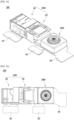
- FIG. 1 is a view showing a camera module 10 according to the related art.
- the camera module 10 employing the related OIS technology has a complex structure because a lens unit 12 is mounted in the actuator 11 and a mechanical driving device is required for lens movement or tilting of the module.
- the gyro sensor 15 or the driving element 16 is arranged in the horizontal direction of the camera module 10, so that the size of the entire camera module is increased, and it is difficult to implement a micro-camera module.
- the circuit board 13 includes a flexible printed circuit board 13a and a rigid printed circuit board 13b, and the gyro sensor 15 is disposed on the rigid printed circuit board (PCB) 31b.
- PCB rigid printed circuit board
- the gyro sensor is disposed to be spaced apart from the camera module 10, it is difficult to accurately detect the degree of movement of the camera module according to the movement of the user. For example, when the camera module 10 is rotated around the gyro sensor 15 by the user, the degree of movement of the gyro sensor 15 and the actuator 11 or the lens unit 12 are moved such that there is a problem that the accuracy of the angular acceleration data is deteriorated due to a large difference in accuracy.
- ultra-slim and micro-miniature camera modules are required.
- the micro-camera module there is a problem in that it is difficult to implement OIS functions applied to general large cameras due to space constraints for OIS operation. So, there is a problem in not being able to implement a very micro camera module.
- the related OIS technology requires a mechanical driving device for lens movement or tilting of the module, so that the structure is complex and power consumption is increased.
- One of the technical problems of the embodiment is to provide an ultra-small, ultra-slim actuator and a camera module including the same.
- one of the technical problems of the embodiment is to provide an actuator and a camera module including the same, capable of securing high precision of the gyro sensor by securing a high precise leveling of the gyro sensor.
- one of the technical problems of the embodiment is, in relation to the arrangement of the gyro sensor of the camera module, to improve the precision of each acceleration and also reducing the error rate due to temperature drift by placing the gyro sensor close to the camera module such that it is intended to provide an actuator and a camera module including the same capable of remarkably improving the precision of a gyro sensor.
- one of the technical problems of the embodiment is to provide an actuator and a camera module including the same so that a sufficient amount of light can be secured by solving the size limitation of the lens in the lens assembly of the optical system when implementing the OIS.
- one of the technical problems of the embodiment is to provide an actuator, and a camera module including the same, capable of preventing magnetic field interference with a magnet for AF or Zoom when implementing OIS.
- one of the technical problems of the embodiment is to provide an actuator and a camera module including the same, capable of implementing OIS with low power consumption.
- the camera module includes a first circuit board 414 on which an image sensor is disposed, a first housing 20 disposed on the first circuit board, a lens assembly disposed in the first housing, and a second circuit board 412 on which a gyro sensor is disposed and disposed on the first side portion 22a of the first housing and a third circuit board 413 disposed on the first side portion 22a of the first housing and having a first region in which a first coil 142b driving the lens assembly is disposed.
- the first coil 142b overlaps with the second circuit board 412 in a direction perpendicular to the optical axis direction.
- the embodiment may include a fourth circuit board 411 connected to the second circuit board and on which a connector is disposed.
- the third circuit board 413 may be disposed on the third side portion 22c of the first housing and the third circuit board 413 may include a third region 413c in which a second coil 412a is disposed and a second region 413b disposed on a second side portion 22b connected between the first side portion and the third side portion of the first housing.
- the first side portion 22a of the first housing includes a first end 22a1 on which the second circuit board 412 is disposed and a second end 22a2. And a step 22as may be formed by the first end and the second end.
- the first side portion of the first housing may include a hole 22ah, and the first coil 142b may be inserted into the hole 22ah.
- the embodiment includes a shield cover in which the first housing is disposed, and the shield cover may have a groove in which the gyro sensor is disposed.
- the invention includes a second housing disposed on the first housing, a prism disposed on the second housing, and an OIS unit disposed between the second housing and the prism
- the embodiment may include a fifth circuit board on which a third coil driving the OIS unit is disposed, and on which the first housing and the second housing are disposed, and the fifth circuit board is connected with the second circuit board.
- the OIS unit may include a lens unit, a shaper unit, and a magnet coupled to the shaper unit and driving the lens unit.
- the second housing may include a second hole, and the third coil may be inserted into the second hole.
- the fifth circuit board may include a region disposed between the second side portion of the first housing and a fourth side portion facing the second side portion, and a region disposed on two sides portions of the second housing.
- the second housing may have a third hole in which a part of the lens unit is disposed.
- the image sensor, the lens assembly, the lens unit, and the prism may overlap in the optical axis direction.
- the actuator according to the embodiment includes a first housing 20 accommodating a lens assembly, a second circuit board 412 disposed on a sidewall of the first housing 20, and a gyro sensor 151 disposed in the second circuit board 412.
- the second circuit board 412 may be disposed extending in a vertical axis direction in a horizontal coordinate plane perpendicular to the optical axis.
- the actuator according to the embodiment may further include a shield cover 510 on an outer surface of the first housing 20.
- the shield cover 510 may include a predetermined support bracket 513, and may include a guide groove 513R in which the second circuit board 412 is disposed in the support bracket 513.
- the precise leveling of the gyro sensor 151 may be secured within 1°.
- the embodiment further includes a second actuator disposed on one side of the actuator, the actuator may be an AF or zoom actuator, and the second actuator may be an OIS actuator.
- the gyro sensor 151 may be spaced apart from the second actuator and disposed perpendicularly to a side surface of the actuator.
- the actuator according to the embodiment may include a first actuator 100 that functions as a zooming function, and a second actuator 200 that is disposed on one side of the first actuator 100 and functions as an OIS.
- the second actuator 200 includes a second housing 210, an OIS unit 220 disposed on the second housing 210, including a shaper unit 222 and a first driving unit 72M, and a second driving unit 72C disposed on the second housing 210.
- the shaper unit 222 includes a shaper body 222a, a protrusion 222b extending laterally from the shaper body 222a and coupled to the first driving unit 72M, and a lens unit 222c disposed on the shaper body 222a.
- the lens unit 222c may also function as a prism for changing a path of light.
- the second actuator 200 may include a prism unit 230 disposed on the OIS unit 220.
- the lens unit 222c of the second actuator 200 may include a light-transmitting support part 222c2, a light-transmitting support part 222c2, a second light-transmitting support part (not shown), a variable prism or a liquid lens.
- the first driving unit 72M of the second actuator 200 includes a magnet coupled to the protrusion 222
- the second driving unit 72C may include a coil coupled to the shaper body 222a.
- the protrusion 222 of the second actuator 200 may include a first protrusion 222b1 and a second protrusion 222b2 respectively extending from the shaper body 222a to one side.
- the first support part b 1e, which is the end of the first protrusion 222b1, and the second support part b2e, which is the end of the second protrusion 222b2 may be spaced apart from each other.
- the camera module according to the embodiment may include an image sensor unit and the actuator disposed at one side of the image sensor unit.
- the embodiment has a technical effect capable of providing a micro-miniature, ultra-thin actuator and a camera module including the same.
- the size of the actuator can be reduced by arranging the gyro sensor 151 on a circuit board disposed perpendicular to the horizontal coordinate axis (x-axis) direction and extending in a horizontal direction to the optical axis (z-axis) direction.
- By controlling the size at the level of the horizontal width of the first housing it is possible to implement an ultra-small and ultra-thin actuator and a camera module including the same.
- a gyro sensor was disposed on a circuit board extending from the actuator in the horizontal coordinate axis (x-axis) direction, and the horizontal width of the circuit board reached about 3 to 4 mm. Since the horizontal area of about 25% or more can be reduced by reducing the horizontal width of the circuit board, there is a technical effect of implementing a micro-miniature, ultra-thin actuator and a camera module including the same.
- the circuit board on which the gyro sensor 151 is disposed in the guide groove 513R of the support bracket 513 can be firmly fixed and disposed, the precise leveling of the gyro sensor 151 can be secured to a high level of the gyro sensor.
- the circuit board on which the gyro sensor 151 is disposed in the guide groove 513R of the support bracket 513 can be firmly fixed and disposed, the precise leveling of the gyro sensor 151 can be secured to a high level of the gyro sensor.
- the support bracket 513 is provided on the shield cover 510, and the support bracket 513 includes a guide groove 513R in which a circuit board is disposed, thereby guiding the support bracket 513.
- the circuit board is firmly fixed and disposed in the groove 513R, there is a special technical effect that can provide a micro-actuator and a camera module including the same as well as a special technical effect that can secure a high precise leveling of the gyro sensor 151.
- the gyro sensor 151 can be placed close to the camera module to improve the accuracy of each acceleration and at the same time improve the accuracy of the gyro sensor by reducing the error rate due to temperature drift such that there is a complex technical effect that can significantly improve the accuracy of the gyro sensor and also provide a micro camera module.
- a support bracket 513 may be provided on the shield cover 510, and the support bracket 513 may include a guide groove 513R in which a circuit board is disposed. Accordingly, the circuit board may be firmly fixedly disposed in the guide groove 513R of the support bracket 513, and the gyro sensor 151 may be disposed close to the camera module. Accordingly, the accuracy of the angular acceleration of the gyro sensor can be improved, and the error rate due to temperature drift can be reduced by disposing the gyro sensor away from the image sensor that generates a lot of heat. Accordingly, there is a complex technical effect capable of providing a micro-camera module while remarkably improving the precision of the gyro sensor.
- the gyro sensor is disposed apart from the lens unit, there is a technical problem in that an error occurs between the movement degree of the lens unit and the movement degree sensed by the gyro sensor according to the user's movement.
- the difference between the degree of movement of the gyro sensor and the degree of movement of the lens unit becomes large, resulting in a problem in that the accuracy of the angular acceleration data is degraded.
- the gyro sensor is closely disposed on the side of the first housing in which the lens unit is disposed, the degree of movement of the lens unit according to the user's movement and the error in movement information detected by the gyro sensor are significantly reduced such that there is a special technical effect that can greatly improve the precision of the angular acceleration of the gyro sensor.
- the actuator and camera module according to the embodiment may solve the problem of lens decenter or tilt during zooming such that there is a technical effect of remarkably improving the image quality or resolution by preventing the occurrence of defocusing or changing the angle of view by matching the alignment between the plurality of lens groups.
- a technical effect that the zooming function can be smoothly performed even in a compact camera module there is a technical effect that a compact camera module can be implemented by arranging the Hall sensor in the inner area of the first coil to reduce the area occupied by the Hall sensor.
- the OIS unit 220 by arranging the OIS unit 220 under the prism unit 230, there is a technical effect that can provide an actuator and a camera module including the same, capable of securing a sufficient amount of light by removing the size limitation of the lens in the lens assembly of the optical system when implementing OIS.
- the embodiment can include an OIS unit 220 stably disposed on the second housing 210a and in the embodiment, OIS may be implemented through the lens unit 222c having the variable prism 222cp using the shaper unit 222 and the first driving unit 72M. Accordingly, there is a technical effect of providing an actuator and a camera module including the same, capable of exhibiting the best optical characteristics by minimizing the occurrence of a decent or a tilt phenomenon.
- a first driving unit 72M which is a magnet driving unit, may be disposed in the second actuator 200 separated from the first actuator 100 such that there is a technical effect of providing an actuator and a camera module including the same, capable of preventing magnetic field interference with an AF or a zoom magnet of the first actuator 100.
- the first driving unit 72M as a magnet driving unit and the second driving unit 72C as the coil driving unit can drive the shaper unit 222 to drive the lens unit 222c including the variable prism to implement OIS. Accordingly, there is a technical effect of providing an actuator and a camera module including the same, capable of implementing OIS with low power consumption.
- the prism unit 230 and the lens unit 222c including the variable prism can be arranged very close, even if the optical path change is finely performed in the lens unit 222c, there is a special technical effect in that the optical path change can be widened in the actual image sensor unit.
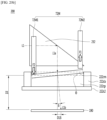
- the lens unit 222c including the variable prism may be disposed very close to the fixed prism 232. Meanwhile, a distance between the lens unit 222c and the image plane 190P of the first lens assembly (not shown) may be secured relatively far. Accordingly, in the variable prism 222cp, the first distance D1 ⁇ reflected on the image plane 190P can be secured widely according to the change in the slope of the predetermined angle ⁇ . Therefore, even if the optical path change is finely performed in the lens unit 222c, there is a special technical effect of ensuring a wide range of optical path changes in the actual image sensor unit.
- first protrusion 222b 1 and the second protrusion 222b2 of the shaper unit 222 may be spaced apart, and the third protrusion 222b3 and the fourth protrusion 222b4 may be spaced apart from each other. Accordingly, when the x-axis or y-axis of each protrusion portion is moved, other protrusions may be less affected. Therefore, there is an effect of improving performance by remarkably reducing the amount of error change generated compared to the target value (ideal) when driving in each axial direction (see FIG. 22 ).
- the second housing 210 may include a jig hole ZH, and the assembly process of the second actuator 200 may be performed while a predetermined jig is firmly coupled to the jig hole ZH of the second housing 210.
- the jig may pass through the jig hole ZH and be led out to the upper side of the second housing 210, and the shaper unit 222 may be firmly disposed on the protruding jig.
- the first to fourth jigs may be disposed to overlap first to fourth protrusions 222b 1, 222b2, 222b3, 222b4 of the shaper body in a vertical direction.
- the first driving unit 72M, the second driving unit 72C, and the like may be firmly coupled to the shaper unit 222, and there is a special technical effect that can significantly prevent the occurrence of tilt (see FIG. 26B ).
- the up (on) or down (under) includes both elements in direct contact with each other or in which one or more other elements are indirectly formed between the two elements.
- the meaning of not only an upward direction but also a downward direction based on one element may be included.
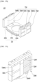
- FIG. 2 is a perspective view showing the camera module 1000 of the embodiment
- FIG. 3A is a perspective view of the camera module 1000 of the embodiment shown in FIG. 2 with the shield cover 510 removed
- FIG. 3B is a plan view of the camera module 1000 of the embodiment shown in FIG. 3A .
- the camera module 1000 of the embodiment may include a single or a plurality of camera modules.
- the embodiment may include a first camera module 1000A and a second camera module 1000B.
- the first camera module 1000A and the second camera module 1000B may be covered by a predetermined shield cover 510.
- the first camera module 1000A may include a single actuator or a plurality of actuators.
- the first camera module 1000A according to the embodiment may include a first actuator 100 and a second actuator 200.
- the first actuator 100 may be electrically connected to the first group of circuit board 410, and the second actuator 200 may be electrically connected to the second group of circuit board 420.
- the second camera module 1000B may be electrically connected to the third group of circuit board 430.
- the first actuator 100 may be a zoom actuator or an auto focus (AF) actuator, and may be electrically connected to the first group of circuit boards 410.
- the first actuator 100 may support one or a plurality of lenses through a predetermined driving unit and may perform an auto focusing function or a zoom function by moving the lenses up and down in response to a control signal from a predetermined controller.
- the second actuator 200 may be an OIS (Optical Image Stabilizer) actuator, and may be electrically connected to the second group of circuit boards 420.
- the second group of circuit boards 420 may be electrically connected to the first group of circuit boards 410.
- the second camera module 1000B may have a fixed focal length lens disposed in a predetermined barrel (not shown), and may be electrically connected to the third group of circuit board 430.
- the fixed focal length lenses may be referred to as "single focal length lenses” or “single lens”.
- an actuator capable of driving a lens unit may be disposed in a predetermined housing (not shown).
- the actuator may be a voice coil motor, a micro actuator, a silicon actuator, or the like, and may be applied in various ways, such as an electrostatic method, a thermal method, a bimorph method, and an electrostatic force method, but is not limited thereto.
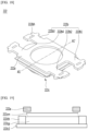
- FIG. 4A is a perspective view of the first actuator 100 in the first direction of the embodiment shown in FIG. 3A
- FIG. 4B is a perspective view of the first actuator 100 of the embodiment shown in FIG. 4A with a part of the first housing 20 removed therefrom.
- FIG. 5A is a perspective view of the first actuator 100 of the embodiment shown in FIG. 4A in a second direction
- FIG. 5B is an exploded perspective view of the first actuator 100 of the embodiment shown in FIG. 5A .
- FIG. 4A is a front perspective view of the device unit 150 including the gyro sensor 151 in the first actuator 100
- FIG. 5A is a perspective view of the first actuator 100 in which the gyro sensor 151 is disposed on the rear surface.
- the z-axis refers to the optical axis direction or a direction parallel thereto
- the xz plane refers to the ground
- the x-axis refers to the ground (xz plane). It means a direction perpendicular to the z-axis
- the y-axis may mean a direction perpendicular to the ground.
- the first actuator 100 includes a first housing 20, a first group of circuit boards 410 and a device unit 150 disposed outside the first housing 20.
- the first housing 20 may include a first housing body 22, a first cover 21 disposed on one side of the first housing body 22, and a second cover 22 disposed on the other side.
- the material of the first housing 20 may be formed of at least one of plastic, glass-based epoxy, polycarbonate, metal, or composite material.
- the first housing 20 may be designed as a master barrel structure that surrounds the entire zoom module to prevent outer material, block light, fix pins, and fix the lens, but is not limited thereto.
- the first cover 21 and the second cover 22 may be fitted in shape with the first housing body 22 and may be coupled by means of an adhesive.
- the first group of circuit boards 410 may include a single or a plurality of circuit boards.
- the first group of circuit boards 410 may include a fourth circuit board 411, a second circuit board 412, a third circuit board 413, and a first circuit board 414.
- the second circuit board 412 is electrically connected to the fourth circuit board 411, and a gyro sensor 151 for detecting movement, a first electronic device 152, and a second electronic device 153 are disposed on the second circuit board 412.
- the first electronic device 152 may be a driver IC
- the second electronic device 153 may be an EEPROM, but is not limited thereto.
- the third circuit board 413 may be electrically connected to a driving unit driving the lens unit, and an image sensor 190 (refer to FIG. 4B ) may be disposed on the first circuit board 414.
- various optical systems such as a first lens assembly 110, a second lens assembly 120, and a third lens group 130 may be disposed on the first housing body 22.
- a first side surface of the first housing body 20 in the direction of the optical axis may be coupled to the first cover 21, and the other side may be coupled to the second cover 22.
- a predetermined image sensor unit 190 may be disposed in the direction of the second cover 22.
- the first cover 21 and the second cover 22 may be coupled to the guide pin 50.
- the guide pin 50 may include a first guide pin 51 and a second guide pin 52 disposed to be spaced apart parallel to the optical axis.
- One end of the first guide pin 51 and the second guide pin 52 may be fixed by being coupled to the first cover 21 and the other end of the second cover 22.
- the first cover 21 may include a first hook (not shown), and a second hook (not shown) protruding from the first cover body in the direction of the first housing body 22 and being disposed in a diagonal direction.
- first housing body 22 may include a first hook coupling portion 26a1 and a second hook coupling portion 26a2 at positions corresponding to the first hook and the second hook and a first hole 26h1 and a second hole 26h2 may be disposed in each of the first hook coupling portion 26a1 and the second hook coupling portion 26a2.
- the first hook and the second hook of the first cover 21 may be coupled to the first hole 26h1 and the second hole 26h2 of the first housing body 22, respectively.
- the first cover 21 may be stably coupled to the first housing body 22 using an adhesive.
- first cover 21 includes a first pin coupling portion (not shown) and a second pin coupling portion (not shown) coupled to the first guide pin 51 and the second guide pin 52, respectively.
- the first guide pin 51 and the second guide pin 52 may be inserted and coupled, respectively.
- a third lens group 130 may be disposed on the first cover 21.
- the third lens group 130 may be a fixed lens, but is not limited thereto.
- a first lens assembly 110 and a second lens assembly may be disposed inside the first housing body 22.
- a bottom groove in which the first lens assembly 110 and the second lens assembly 120 move can be formed parallel to the optical axis z direction on the bottom surface of the first housing body 22.
- the bottom groove may have a downward concave shape according to the outer circumference shape of the lens, but is not limited thereto.
- a third driving part 141 and a fourth driving part 142 may be disposed on both sides of the body 20 of the first housing.
- FIG. 6 is a perspective view showing the first actuator 100 in the embodiment shown in FIG. 5A while the first housing body 22, the first cover 21, and the second cover 22 are removed therefrom, and the lens itself is omitted.
- an optical system and a lens driver may be disposed on the first housing body 22 of the first actuator 100.
- the first actuator 100 includes at least one or more of a first lens assembly 110, a second lens assembly 120, a third lens group 130, and a guide pin 50 in the first housing body 22.
- the third driving unit 141 and the fourth driving unit 142 may be disposed outside the first housing body 22, thereby performing a high magnification zooming function.
- first lens assembly 110 the second lens assembly 120, the third lens group 130, and the image sensor unit may be classified as optical systems.
- the third driving unit 141, the fourth driving unit 142, and the guide pin 50 may be classified as a lens driving unit, and the first lens assembly 110 and the second lens assembly 120 also function as a lens driving unit.
- the third driving unit 141 and the fourth driving unit 142 may be driving units including a coil and a yoke, but are not limited thereto.
- the guide pin 50 may perform a guide function of a lens assembly to be moved, and may be provided in a single or plural number.
- the guide pin 50 may include a first guide pin 51 and a second guide pin 52, but is not limited thereto.
- the guide pin 50 may be referred to as a rod or a shaft, but is not limited thereto.
- a predetermined prism may be disposed on the side of the third lens group 130, and a predetermined image sensor unit 190 may be disposed on the side of the second cover 22.
- the prism may also be included in the optical system.
- the prism may change incident light into parallel light.
- the prism may change the incident light into parallel light by changing the optical path of the incident light to an optical axis (z-axis) parallel to the central axis of the lens group. Thereafter, the parallel light passes through the third lens group 130, the first lens assembly 110, and the second lens assembly 120 and enters the image sensor unit 190 to capture an image.
- the prism may be an optical member having a triangular column shape.
- the embodiment may employ a reflector or a reflective mirror instead of or in addition to a prism.
- an additional prism may be provided so that light that has passed through the lens group is captured by the image sensor unit.
- the image sensor unit 190 may be disposed perpendicular to the optical axis direction of parallel light.
- the image sensor unit may include a solid-state imaging device disposed on a predetermined first circuit board 414.
- the image sensor unit 190 may include a Charge Coupled Device (CCD) image sensor or a Complementary Metal-Oxide-Semiconductor (CMOS) image sensor.
- CCD Charge Coupled Device
- CMOS Complementary Metal-Oxide-Semiconductor
- optical axis direction z may mean a direction that is the same as or parallel to the direction in which the lens groups are aligned.
- the first actuator 100 may perform a zooming function.
- the first lens assembly 110 and the second lens assembly 120 may be moving lenses that move through the third driving unit 141, the fourth driving unit 142 and the guide pin 50, and the third lens group 130 (refer to FIG. 5 ) may be a fixed lens, but is not limited thereto.
- the third lens group 130 may perform a function of a focator for forming parallel light at a specific position.
- the first lens assembly 110 may perform a variable function of re-forming an image formed by the third lens group 130 as a concentrator to another location. Meanwhile, in the first lens assembly 110, the magnification change may be large due to the large change in the distance or the image distance to the subject.
- the image point of the image in the first lens assembly 110 which is a variable factor, may be slightly different depending on the location.
- the second lens assembly 120 may perform a position compensation function for an image formed by a variable power factor.
- the second lens assembly 120 performs a function of a compensator that performs a role of accurately forming an image point formed in the first lens assembly 110, which is a variable factor, at the position of the actual image sensor unit.
- the actuator may include a mover and a fixing part.
- the mover is a concept corresponding to a fixed part and may be referred to as a moving part.
- the mover may refer to the first and second lens assemblies 110 and 120 that are moved through the guide pin 50.
- the fixing part may mean the first housing 20, the guide pin 50, the third driving part 141, the fourth driving part 142, and the like that are not moved.
- one or more guide pins 50 may be disposed parallel to the optical axis (z-axis).
- the guide pin 50 may include a first guide pin 51 and a second guide pin 52 that are spaced apart from each other in parallel to the optical axis direction.
- the first guide pin 51 and the second guide pin 52 are coupled to the first cover 21, the second cover 22 of the first housing (refer to FIG. 5 ), and may function as a movement guide of the first lens assembly 110, the second lens assembly 120.
- the guide pin 50 may be formed of at least one of plastic, glass-based epoxy, polycarbonate, metal, or composite material, but is not limited thereto.
- the first lens assembly 110 and the second lens assembly 120 may be driven by electromagnetic force due to interaction with the third driving unit 141 and the fourth driving unit 142, respectively, but are not limited thereto.
- the third driving unit 141 and the fourth driving unit 142 may be driving units having a coil and a yoke.
- the third driving unit 141 may include a second yoke 141a and a second coil unit 141b
- the fourth driving unit 142 may include a first yoke 142a and a first coil unit 142b.
- the first lens assembly 110 of the embodiment may include one or more of the first housing 112, the first lens group (not shown), and the first magnet 116.
- the first housing 112 may include a first lens housing 112a accommodating a first lens group (not shown) and a first driving unit housing 112b accommodating the first magnet 116.
- the lens housing may be referred to as a lens barrel, but is not limited thereto.
- first housing 112 further includes a first-second yoke (not shown) under the first magnet 116 inside the first driving unit housing 112b, so that the magnetic force of the first magnet 116 can be blocked not to affect the inside of the housing body 22.
- the second lens assembly 120 of the embodiment may include one or more of the second housing 122, the second lens group (not shown), and the second magnet 126.
- the second housing 122 may include a second lens housing 122a accommodating a second lens group (not shown) and a second driving unit housing 122b accommodating the second magnet 126.
- the second lens housing 122a may include a fifth pin guide part 122p5 fitted to the first guide pin 51.
- the second housing 122 further includes a second-second yoke (not shown) under the second magnet 126 inside the second driving unit housing 122b, so that the magnetic force of the second magnet 126 can be blocked not to affect the inside of the housing body 22.
- the first lens assembly 110 will be described with reference to FIGS. 7 and 8 .
- FIG. 7 is a perspective view of a first lens assembly 110 and a third driving unit 141 in the first actuator 100 according to the embodiment shown in FIG. 6
- FIG. 8 is an example of interaction between the first magnet 116 and the second coil unit 141b in the first actuator 100.
- the first lens assembly 110 may include a first lens housing 112a and a first driving unit housing 112b.
- the first lens housing 112a functions as a barrel or a container, and a first lens group (not shown) may be mounted.
- the first lens group (not shown) may be a moving lens group, and may include a single lens or a plurality of lenses.
- the second housing 122 of the second lens assembly 120 may also include a second lens housing 122a and a second driving unit housing 122b.
- a first magnet 116 may be disposed on the first driving part housing 112b of the first lens assembly 110.
- the first magnet 116 of the first lens assembly 110 may be a magnet driving unit, but is not limited thereto.
- the first magnet 116 may include a first magnet that is a permanent magnet.
- the second driving unit 126 of the second lens assembly 120 may also be a magnet driving unit, but is not limited thereto.
- the magnetization method of the first magnet 116 may be a vertical magnetization method.
- both the N pole 116N and the S pole 116S of the first magnet 116 may be magnetized to face the second coil part 141b.
- the N-pole 116N and the S-pole 116S of the first magnet 116 may be disposed so as to correspond to a region in which the current flows in the y-axis direction perpendicular to the ground in the second coil unit 141b.
- a magnetic force DM may be applied in a direction opposite to the x-axis at the N pole 116N of the first magnet 116 and a current DE may flow in the y-axis direction in the region of the second coil part 141b corresponding to the N pole 116N. Accordingly, electromagnetic force DEM may act in the z-axis direction according to Fleming's left-hand rule.
- a magnetic force DM may be applied in the x-axis direction from the S pole 116S of the first magnet 126 and a current DE may flow in a direction opposite the y-axis perpendicular to the ground in the second coil part 141b corresponding to the S pole 116S. Accordingly, electromagnetic force DEM may act in the z-axis direction according to Fleming's left-hand rule.
- the third driving unit 141 including the second coil unit 141b is in a fixed state such that the first lens assembly 110, which is a mover in which the first magnet 116 is disposed, may be moved back and forth in a direction parallel to the z-axis direction by the electromagnetic force DEM according to the current direction.
- the electromagnetic force DEM may be controlled in proportion to the current DE applied to the second coil unit 141b.
- electromagnetic force DEM is generated between the second magnet 126 and the first coil unit 142b, so that the second lens assembly 120 may be moved horizontally with respect to the optical axis.
- the first driving unit housing 112b may guide the first lens assembly 110 in the optical axis direction by having at least one pin guide part 112p.
- the pin guide part 112p may include the first pin guide part 112p1 and the second pin guide part 112p2.
- the first driving part housing 112b may include a first pin guide part 112p1 protruding upward, and a first guide hole 112h1 may be disposed in the first pin guide part 112p1.
- first driving part housing 112b may further include a second pin guide part 112p2 protruding upward and spaced apart from the first pin guide part 112p1.
- a second guide hole 112h2 may be disposed in the second pin guide part 112p2.
- the first guide pin 51 is inserted into the first and second guide holes 112h1 and 112h2 of the first pin guide part 112p1 and the second pin guide part 112p2, so that the first lens assembly 110 can be precisely guided parallel to the optical axis direction.
- the first pin guide part 112p1 and the second pin guide part 112p2 of the first housing 112 contact the first guide pin 51 to minimize the contact area to each other, thereby reducing frictional resistance. Accordingly, according to the embodiment, there are technical effects such as improvement of driving force and reduction of power consumption by preventing occurrence of friction torque during zooming.
- a region other than the first pin guide part 112p1 and the second pin guide part 112p2 is removed from the upper region of the first driving part housing 112b where the first guide pin 51 is located. Accordingly, by reducing the weight of the first driving unit housing 112b, frictional resistance can be reduced, thereby improving driving force during zooming, reducing power consumption, and improving control characteristics.
- the first lens housing 112a includes at least one pin guide part 112p protruding to the side, such that it is possible not only to guide the movement of the first lens assembly 110 in the optical axis direction, but also to prevent the central axis from being distorted by preventing the lens unit from tilting upward and downward.
- the first lens housing 112a may include a third pin guide part 112p3 protruding to the side, and a first guide groove 112r1 may be disposed in the third pin guide part 112p3.
- the second guide pin 52 can be inserted into the first guide groove r1 of the third pin guide part 112p3, so that the first lens assembly 110 can be precisely guided parallel to the optical axis direction.
- tilting of the lens portion upward and downward may be prevented, thereby preventing the central axis from twisting.
- the third pin guide portion 112p3 in the first lens housing 112a may contact the second guide pin 52, so frictional resistance can be prevented by minimizing the frictional area, and there are technical effects such as improvement of driving force, reduction of power consumption, and improvement of control characteristics during zooming.
- the friction torque can be reduced by reducing the weight of the first lens housing 112a, thereby improving driving force during zooming, reducing power consumption, and improving control characteristics.
- the embodiment by removing an area other than the third pin guide part 112p3 from the side area of the first lens housing 112a where the second guide pin 52 is located, it is possible to reduce the weight and reducing the friction torque, so there are technical effects such as improvement in driving force during zooming, reduction in power consumption and improvement in control characteristics.
- FIG. 9 is a partial perspective view of the first actuator 100 shown in FIG. 7 .
- the third driving unit 141 may further include a first Hall sensor 143a inside the second coil unit 141b.
- a compact camera module can be implemented by arranging the first Hall sensor 143a in the inner area of the second coil unit 141b to reduce the area occupied by the Hall sensor.
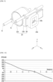
- FIG. 10 is a graph showing Hall sensor linearity according to a stroke of the first camera module 1000 shown in FIG. 9 .
- Hall Linearity is very excellent when the stroke of the lens assembly in the first actuator 100 according to the implementation is about 4 mm.
- the first Hall sensor 143a is placed in the center of the first driving magnet 116, there is a technical effect in that only one first Hall sensor 143a can greatly improve the reliability of the position measurement of the lens.
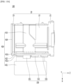
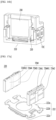
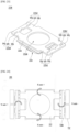
- FIG. 11A is a detailed perspective view of the first actuator 100 of the embodiment
- FIG. 11B is a plan view of the first actuator 100 of the embodiment shown in FIG. 11A .
- the first group of circuit board 410 of the first actuator 100 of the embodiment may include a single or a plurality of circuit boards.
- the first group of circuit board 410 may include a fourth circuit board 411, a second circuit board 412, a third circuit board 413, a first circuit board 414, a first connection substrate 411C and a second connection substrate 412C.
- the second circuit board 412 may include a gyro sensor 151 that senses motion, a first electronic device 152, and a second electronic device 153.
- the first electronic device 152 may be a driver IC
- the second electronic device 153 may be an EEPROM, but is not limited thereto.
- the third circuit board 413 may be electrically connected to a driving unit driving the lens unit, and an image sensor 190 may be disposed on the first circuit board 414.
- the fourth circuit board 411 and the second circuit board 412 may be electrically connected by a first connection board 411c, and the second circuit board 412 and the first circuit board 414 may be electrically connected by the connection substrate 412c.
- the first group of circuit boards 410 may It may include any substrate with a wiring pattern such as a rigid printed circuit board (Rigid PCB), a flexible printed circuit board (Flexible PCB), a rigid flexible printed circuit board (Rigid Flexible PCB), and the like.
- first to fourth circuit boards 414, 412, 413, and 411 may be rigid printed circuit boards (Rigid PCB), and the first and second connection boards 411c and 412c may be a flexible PCB or a rigid flexible PCB, but is not limited thereto.
- the first actuator 100 of the embodiment may detect motion by employing the gyro sensor 151 and may move the lens to correct the optical path, thereby implementing OIS technology to correct image quality.
- the movement of the camera module may largely include a linear movement that moves along an axis and a rotational movement that rotates about the axis.
- the linear movement may include a movement in the horizontal coordinate axis (x-axis) direction of the camera module, a movement in the vertical coordinate axis (y-axis) direction of the camera module, and a movement in the optical axis (z-axis) direction arranged in the front-rear direction of the camera module.
- the rotational movement may include a Pitch meaning a vertical rotational movement using the horizontal coordinate axis (x axis) of the first actuator 100 as a rotation axis, a yaw meaning a left-right rotational movement using the vertical coordinate axis (y-axis) of the first actuator 100 as a rotation axis, and a roll meaning a rotational movement of the optical axis (z-axis) passing in the front and rear direction of the first actuator 100 as a rotation axis.
- a Pitch meaning a vertical rotational movement using the horizontal coordinate axis (x axis) of the first actuator 100 as a rotation axis
- a yaw meaning a left-right rotational movement using the vertical coordinate axis (y-axis) of the first actuator 100 as a rotation axis
- a roll meaning a rotational movement of the optical axis (z-axis) passing in the front and rear direction of the first actuator 100 as a rotation axis.
- the gyro sensor 151 may employ a two-axis gyro sensor that detects two rotational motion amounts of pitch and yaw representing a large movement in a two-dimensional image frame, and more accurate hand shake.
- a 3-axis gyro sensor that detects all the amount of movement of the pitch, yaw, and roll may be employed.
- the movement corresponding to the pitch, yaw, and roll detected by the gyro sensor 151 may be converted into an appropriate physical quantity according to a camera shake correction method and a correction direction.
- the fourth circuit board 411 may be disposed to extend in the horizontal coordinate axis (x-axis) direction of the first actuator 100, and the second circuit board 412 may be disposed in a y-axis direction perpendicular to the horizontal coordinate axis (x-axis) direction. In this case, the second circuit board 412 may be disposed to extend in a direction horizontal to the optical axis (z-axis) direction.
- the gyro sensor 151 is disposed on the second circuit board 412, there is a technical effect of implementing a micro camera module.
- the gyro sensor 151 is disposed on the second circuit board 412 which is vertical to the horizontal coordinate axis (x-axis) direction and extends in a horizontal direction to the optical axis (z-axis) direction. Accordingly, by controlling the size of the first actuator 100 to the level of the horizontal width of the first housing 20, there is a technical effect of implementing a micro camera module.
- the area of the circuit board area extending in the horizontal coordinate axis (x-axis) direction in which the gyro sensor was disposed in the related internal technology can be reduced by an area of about 3 to 4 mm or more (about 25% or more) such that there is a technical effect that can implement a micro camera module.
- the gyro sensor 151 may be disposed on the second circuit board 412 disposed to be perpendicular to the horizontal coordinate axis (x-axis) direction and extended in a horizontal direction to the optical axis (z-axis) direction. Accordingly, the central axis of the gyro sensor 151 may be horizontal in the horizontal coordinate axis (x-axis) direction but perpendicular to the optical axis (z-axis) direction.
- the second circuit board 412 may be disposed extending in a vertical axis direction in a horizontal coordinate plane perpendicular to the optical axis.
- the pitch movement may be controlled by replacing the roll and the roll movement by the pitch, but the present disclosure is not limited thereto.
- the pitch movement may be set as a pitch
- the roll movement may be set as a roll
- the gyro sensor is disposed apart from the lens unit, there is a technical problem in that an error occurs between the movement degree of the lens unit and the movement degree sensed by the gyro sensor according to the user's movement.
- the difference between the degree of movement of the gyro sensor and the degree of movement of the lens unit becomes large, resulting in a problem in that the accuracy of the angular acceleration data is degraded.
- the gyro sensor 151 may be disposed in close contact with the side of the first housing 20 of the first actuator 100 in which the lens unit is disposed. Accordingly, the degree of movement of the lens unit according to the movement of the user and the error of movement information detected by the gyro sensor can be significantly reduced. Therefore, there is a special technical effect that can greatly improve the precision of the angular acceleration of the gyro sensor.
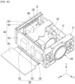
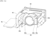
- FIG. 11C is a perspective view of the camera module of the embodiment shown in FIG. 11A in which the first housing is removed from the first actuator
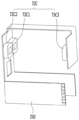
- FIG. 11D is a bottom view of a perspective view in which the first housing is removed from the first actuator in the camera module of the embodiment shown in FIG. 11C
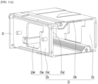
- FIG. 11E is a perspective view of a first housing in a first actuator in the camera module of the embodiment shown in FIG. 11A and a detailed perspective view of the first housing body 22.
- the actuator may include a first circuit board 414 on which an image sensor 190 is disposed, and a first housing 20 disposed on the first circuit board 414, lens assembly 110 and 120 disposed in the first housing 20, a second circuit board 412 disposed on the first side portion 22a of the first housing 20 on which the gyro sensor 151 is disposed, and a third circuit board 413 driving the lens assembly.
- the first housing base 22 of the first housing 20 may include a first side portion 22a, a second side portion 22b, and a third side portion 22c.
- the first side portion 22a of the first housing may include a first end 22a1 on which the second circuit board 412 is disposed and a second end 22a2, and a step 22as may be formed by the first end 22a1 and the second end 22a2.
- the first side portion 22a of the first housing 20 may include a hole 22ah, and the first coil 142b may be firmly inserted into the hole 22ah.
- the third circuit board 413 may be disposed on the first side portion 22a of the first housing, and the third circuit board 413 may include a first region 413a in which the first coil 142b driving the lens assembly is disposed.
- first coil 142b may overlap the second circuit board 412 in a direction perpendicular to the optical axis direction.
- the embodiment may include a fourth circuit board 411 connected to the second circuit board 412 and on which a connector 411c is disposed.
- the third circuit board 413 may include a third region 413c disposed on the third side portion 22c of the first housing and in which the second coil 412a is disposed and a second region 413b disposed on a second side portion 22b connecting between the first side portion 22a and the third side portion 22c of the first housing.
- FIG. 12A is a perspective view of a shield can in the camera module of the embodiment shown in FIG. 2
- FIG. 12B is a bottom perspective view of a shield can in the camera module of the embodiment shown in FIG. 12A
- FIG. 13 is a partially enlarged view of a shield can in the camera module of the embodiment shown in FIG. 12B .
- a shield cover 510 may be additionally installed on the outer surface of the first housing of each camera module.
- the shield cover 510 may also be referred to as a cover housing.
- the shield cover 510 may include a first shield region 510A corresponding to the first actuator 100, a second shield region 510B corresponding to the second actuator 200, and a third shield region 510C corresponding to a second camera module 1000B.
- the shield cover 510 may be formed of a metal material such as steel SUS, and may shield electromagnetic waves flowing into and out of the camera module, and also prevent outer material from entering the camera module.
- a first recess 511a in which the first group of circuit boards 410 is disposed may be provided at a lower end of the first shield region 510A.
- a second recess 511b in which the second group of circuit boards 420 is disposed may be provided at a lower end of the second shield region 510B.
- a support bracket 513 may be provided on the shield cover 510, and a guide groove 513R in which the gyro sensor 151 is disposed may be included in the support bracket 513.
- the gyro sensor 151 can be firmly fixedly disposed in the guide groove 513R of the support bracket 513, the precise leveling of the gyro sensor 151 can be secured high.
- the precise leveling of the gyro sensor 151 can be very precisely secured within about 1°.
- the support bracket 513 is provided on the shield cover 510, and the gyro sensor 151 is provided by including a guide groove 513R in which the gyro sensor 151 is disposed in the support bracket 513.
- the gyro sensor 151 can be rigidly fixedly disposed, there is a special technical effect that can secure a high precise leveling of the gyro sensor 151 and a special technical effect that can provide a micro-miniature camera module.
- the guide groove 513R may be referred to as a recess, but is not limited thereto.
- a support bracket 513 is provided on the shield cover 510, and a guide groove 513R in which the gyro sensor 151 is disposed may be included in the support bracket 513 such that the gyro sensor 151 can be rigidly fixedly disposed and can be disposed close to the driving unit and the lens unit of the camera module. Therefore, the accuracy of the angular acceleration can be improved, and the error rate due to temperature drift can be reduced by disposing the gyro sensor away from the image sensor 190, which generates a lot of heat such that there is a complex technical effect that can provide a micro camera module while remarkably improving the precision of the gyro sensor.
- the difference between the degree of movement of the gyro sensor and the degree of movement of the lens unit becomes large, resulting in a problem in that the accuracy of the angular acceleration data is degraded.
- the gyro sensor is closely disposed on the side of the first housing 20 in which the lens unit is disposed, the degree of movement of the lens unit according to the user's movement and the error in movement information detected by the gyro sensor are greatly reduced such that the accuracy of the angular acceleration of the sensor can be remarkably improved.
- the second actuator 200 may be an OIS (Optical Image Stabilizer) actuator, but is not limited thereto.
- OIS Optical Image Stabilizer
- FIG. 14A is a perspective view of a second actuator in a first direction in the camera module of the embodiment shown in FIG. 3A and FIG. 14B is a perspective view of a second actuator in a second direction in the camera module of the embodiment shown in FIG. 3A .
- the second actuator 200 of the embodiment may include a second housing 210, an OIS unit 220 disposed on the second housing 210, a prism unit 230 disposed on the OIS unit 220, and a second driving unit 72C (see FIG. 15 ) electrically connected to the second circuit board 250.
- the OIS unit 220 disposed on the second housing 210, there is a technical effect of providing an ultra-slim, ultra-small actuator, and a camera module including the same.
- the OIS unit 220 stably disposed on the second housing 210 is provided, and the variable prism 222cp including the shaper unit 222 and the first driving unit 72M, which will be described later, is provided.
- OIS is implemented through the provided lens unit 222c, there is a technical effect of minimizing the occurrence of a decent or a tilt phenomenon to produce the best optical characteristics.
- the first driving unit 72M which is a magnet driving unit
- the first driving unit 72M may be disposed in the second actuator 200 separated from the first camera actuator 100, accordingly, there is a technical effect capable of preventing magnetic field interference with the AF of the first actuator 100 or the magnet for zoom.
- the OIS may be implemented using the shaper unit 222 and the first driving unit 72M for the lens unit 222c including the variable prism 222cp, unlike moving a plurality of conventional solid lenses such that there is a technical effect that can implement OIS with low power consumption.
- the second actuator 200 of the embodiment will be described in more detail with reference to the following drawings.
- FIG. 15 is a perspective view of a second circuit board 250 and a second driving unit 72C of the second actuator 200 of the embodiment shown in FIG. 14B
- FIG. 16A is a partially exploded perspective view of the second actuator 200 of the embodiment shown in FIG. 14B
- FIG. 16B is a perspective view of the second circuit 200 board removed from the second actuator of the embodiment shown in FIG. 14B .
- the second circuit board 250 may be connected to a predetermined power supply unit (not shown) to apply power to the second driving unit 72C.
- the second circuit board 250 is a circuit board having a wiring pattern that can be electrically connected, such as a rigid printed circuit board (Rigid PCB), a flexible printed circuit board (Flexible PCB), and a rigid flexible PCB.
- the second driving unit 72C may include a single or a plurality of unit driving parts, and may include a plurality of coils.
- the second driving unit 72C may include a fifth unit driving part 72C1, a sixth unit driving part 72C2, a seventh unit driving part 72C3, and an eighth unit driving part (not shown).
- the second driving unit 72C may further include a Hall sensor (not shown) to recognize the position of the first driving unit 72M (see FIG. 16A ) to be described later.
- a first Hall sensor (not shown) in the fifth unit driving part 72C1 and a second Hall sensor (not shown) in the seventh unit driving part 72C3 may be further included.
- the embodiment includes an OIS unit 220 stably disposed on the second housing 210 and OIS can be implemented for the lens unit 222c including the variable prism by using the second driving unit 72C, which is a coil driving unit, and the first driving unit 72M, which is a magnet driving unit such that it is possible to achieve the best optical characteristics by minimizing the occurrence of decent or tilt.
- the second driving unit 72C which is a coil driving unit
- the first driving unit 72M which is a magnet driving unit such that it is possible to achieve the best optical characteristics by minimizing the occurrence of decent or tilt.
- a lens unit 222c including a variable prism can be driven by using a first driving unit 72M as a magnet driving unit and a second driving unit 72C as a coil driving unit.
- Unit 222 such that there is a technical effect that OIS can be implemented with low power consumption by driving the shaper unit 222.
- the second actuator 200 of the embodiment may include a second housing 210, an OIS unit 220 disposed on the second housing 210 and including a shaper unit 222, a first driving unit 72M, a second driving unit 72C disposed on the second housing 210, and a prism unit 2230 including a fixed prism 232 and disposed on the OIS unit 220.
- the second housing 210 has a predetermined opening 212H through which light can pass through the housing body 212, and a housing side portion 214P extending above the housing body 212 and including a driving unit hole 214H in which the driving unit 72C is disposed.
- the second housing 210 may extend above the housing body 212 and may include a first housing side portion 214P1 including a first driving unit hole 214H1 in which the second driving unit 72C is disposed, and a second housing side portion 214P2 including a second driving unit hole 214H2 in which the second driving unit 72C is disposed.
- the second driving unit 72C may be disposed on the housing side portion 214P such that OIS can be implemented by driving the shaper unit 222 with respect to the lens unit 222c including the variable prism through electromagnetic force together with the first driving unit 72M, which is a magnet driving unit, so it is possible to implement OIS with low power consumption.
- the lens unit 222c including the variable prism can be controlled through the second driving unit 72C stably fixed to the housing side 214P and the first driving unit 72M, which is a magnet driving unit, thereby implementing OIS.
- the second driving unit 72C stably fixed to the housing side 214P and the first driving unit 72M, which is a magnet driving unit, thereby implementing OIS.
- the fixed prism 232 may be a right-angle prism, and may be disposed inside the first driving unit 72M of the OIS unit 220.
- a predetermined prism cover 234 is disposed on the upper side of the fixed prism 232 so that the fixed prism 232 can be closely coupled to the second housing 210 so that there is a technical effect that prevents prism tilt and does not cause decenter in the second actuator 200.
- the prism unit 230 and the lens unit 222c including the variable prism can be arranged very close, there is a special technical effect in that even if the optical path change is finely performed in the lens unit 222c, the optical path change can be widened in the actual image sensor unit.
- the second movement path L1a of the light beam changed by the fixed prism 232 may be changed in the variable prism 222cp to be changed to the third movement path L1b.
- the lens unit 222c including the fixed prism 232 and the variable prism may be arranged very close. Accordingly, a distance between the lens unit 222c and the image plane 190P of the first lens assembly (not shown) can be secured relatively far.
- the gyro sensor 151 on the first actuator 100 as shown in FIGS. 11A and 11B , the movement of the camera module is detected to change the slope of the predetermined angle ⁇ of the variable prism 222cp.
- OIS technology that corrects the image quality can be implemented by modifying the optical path.
- the gyro sensor is disposed apart from the lens unit, there is a technical problem in that an error occurs between the movement degree of the lens unit and the movement degree sensed by the gyro sensor according to the user's movement.
- the difference between the degree of movement of the gyro sensor and the degree of movement of the lens unit becomes large, resulting in a problem in that the accuracy of the angular acceleration data is degraded.
- the gyro sensor 251 is disposed in close contact with the side of the first housing 20 in which the lens unit is disposed, the degree of movement of the lens unit according to the user's movement and the error of movement information detected by the gyro sensor are significantly reduced. As a result, there is a special technical effect that can greatly improve the precision of the angular acceleration of the gyro sensor.
- FIG. 17A is an exploded perspective view of the OIS unit 220 of the second actuator 200 of the embodiment shown in FIG. 16A
- FIG. 17B is a combined perspective view of the OIS unit 220 of the second actuator of the embodiment shown in FIG. 17A
- FIG. 17C is an exploded perspective view of the first driving unit 72M in the OIS unit 220 shown in FIG. 17A .
- the OIS unit 220 may include a shaper unit 222 and a first driving unit 72M.
- the shaper unit 222 may include a protrusion 222b extending laterally from the shaper body 222a including a hole through which light can pass and the shaper body 222a, and is coupled to the first driving unit 72M in a first vertical direction.
- the shaper unit 222 may include a lens unit 222c disposed on the shaper body 222a in a second vertical direction opposite to the first vertical direction and including a variable prism.
- OIS can be implemented for the lens unit 222c including the variable prism using the OIS unit 220 including the shaper unit 222 and the first driving unit 72M such that there is a technical effect of minimizing the occurrence of a decent or a tilt phenomenon to produce the best optical characteristics.
- the first driving unit 72M may include a single or a plurality of magnet frames 72MH1 and 72MH2 coupled to the protrusion 222b and a unit driving part disposed on the magnet frames 72MH1, 72MH2.
- the first driving unit 72M may include a first magnet frame 72MH1 and a second magnet frame 72MH2.
- a first unit driving part 72M1, a second unit driving part 72M2 may be disposed in the first magnet frame 72MH1 and a third unit driving part 72M3, a fourth unit driving part 72M4 may be disposed in the second magnet frame 72MH2.
- Each of the first to fourth unit driving parts 72M1, 72M2, 72M3, and 72M4 may include first to fourth magnets.
- FIG. 17C is an exploded perspective view of the first driving unit 72M in the OIS unit 220 shown in FIG. 17A .
- the first driving unit 72M may further include yokes 72MY disposed on the first and second magnet frames 72MH1 and 72MH2 to block interference of a magnetic field.
- the first magnet frame 72MH1 of the first driver 72M may have a frame groove 72MR, and a yoke 72MY may be disposed in the frame groove 72MR. Thereafter, the first unit driving part 72M1 and the second unit driving part 72M2 may be respectively disposed on the yoke 72MY.
- the yoke 72MY may have a yoke protrusion 72MYP and may be firmly coupled to the protrusion 222b of the shaper unit 222.
- FIG. 18 is a perspective view of the shaper unit 222 of the second actuator of the embodiment shown in FIG. 17A .
- the shaper unit 222 may include a shaper body 222a including an opening through which light can pass, a protrusion 222b extending laterally from the shaper body 222a and coupled to the first driving part 72M in a first vertical direction, and a lens unit 222c disposed on the shaper body 222a in a second vertical direction opposite to the first vertical direction including a variable prism 222cp.
- the shaper unit 222 may include a plurality of magnet support portions respectively extending from the shaper body 222a to both sides.
- the shaper unit 222 may include a first protrusion 222b1, a second protrusion 222b2 branching from the shaper body 222a to a first side and extending, and a third protrusion 222b3, a fourth protrusion 222b4 branching and extending toward the second side.
- the first driving unit 72M may include first to fourth unit driving parts 72M1, 72M2, 72M3, and 72M4 respectively coupled to the first to fourth protrusions 222b 1, 222b2, 222b3, and 222b4.
- the shaper unit 222 may include a coupling groove 222bh in the magnet support portion to be coupled to a magnet frame. Accordingly, the OIS unit 220 as shown in FIG. 17B may be combined.
- the OIS is implemented through the optical path control of the lens unit 222c having a variable prism such that there is a technical effect that can produce the best optical properties by minimizing the occurrence of phenomena.
- FIG. 19 is a cross-sectional view of the lens unit 222c along the line A1-A1' of the shaper unit 222 shown in FIG. 18 .
- the lens unit 222c may include a light-transmitting support part 222c2, a bracket 222cb disposed on the light-transmitting support part 222c2 with a predetermined accommodation space, a variable prism 222cp disposed in the receiving space of the bracket 222cb, a flexible plate 222cm disposed on the variable prism 222cp, and a second light-transmitting support (not shown) disposed on the flexible plate 222cm.
- the light-transmitting support part 222c2 and the second light-transmitting support part may be formed of a light-transmitting material.
- the light-transmitting support part 222c2 and the second light-transmitting support part may be formed of glass, but are not limited thereto.
- the light-transmitting support part 222c2 and the second light-transmitting support part may have a hollow circular ring shape or a prismatic ring shape.
- the size of the second light-transmitting support part may be formed to be smaller than the size of the accommodation space of the bracket 222cb.
- variable prism 222cp may include an optical liquid disposed in a space formed by the translucent support 222c2, the support bracket 222cb, and the flexible plate 222cm, or may include a wedge prism.
- the optical liquid for the variable prism 222cp can be transparent, may have low fluorescence, and may not be toxic.
- the optical liquid of the embodiment may employ a chlorofluorocarbon (CFC) component, but is not limited thereto.
- the bracket 222cb may be formed of an elastic material or a non-stretch material.
- the bracket 222cb may be made of an elastic film or a metal material, but is not limited thereto.
- the flexible plate 222cm may receive a predetermined force by the shaper body 222a according to the movement of the first driving part 72M, a part of the flexible plate 222cm may move upward or downward due to the characteristic of a flexible elastic material as shown in FIG. 20B , and the shape of the variable prism 222cp may be variable.
- the flexible plate 222cm may be a reverse osmosis (RO) membrane, a nano filtration (NF) membrane, an ultra-filtration (UF) membrane, a micro filtration (MF) membrane, etc., but is not limited thereto.
- RO reverse osmosis
- NF nano filtration
- UF ultra-filtration
- MF micro filtration
- the RO membrane is a membrane having a pore size of about 1 to 15 angstroms
- the NF membrane is a membrane having a pore size of about 10 angstroms
- the UF membrane is a membrane having a pore size of about 15 to 200 angstroms
- the MF membrane may be a membrane having a pore size of about 200 to 1000 angstroms.
- the embodiment may include an OIS unit 220 stably disposed on the second housing 210, and OIS can be implemented for a lens unit 222c including a variable prism 222cp using the shaper unit 222 and the first driving unit 72M such that there is a technical effect that can produce the best optical characteristics by minimizing the occurrence of decent or tilt.
- FIGS. 20A to 20B are diagrams illustrating the operation of the first actuator 100 according to the embodiment.
- FIG. 20A is an exemplary view before the operation of the OIS actuator of the embodiment
- FIG. 20B is an exemplary view after the operation of the OIS actuator of the embodiment.
- the prism may include a fixed prism 232 that changes the path of a predetermined light beam, and a variable type prism 222cp that is disposed under the fixed prism 232 and changes the path of light rays emitted from the fixed prism 232.
- the second actuator 200 of the embodiment can control the optical movement path by changing the shape of the variable prism 222cp through the first driving unit 72M and the second driving unit 72C.
- the second actuator 200 may control the path of the light beam by changing the vertex angle ⁇ of the variable prism 222cp through the first driving unit 72M, which is a magnet driving unit.
- the incident light ray L1 can be changed to the second movement path L1a by the fixed prism 232, but the optical path is not changed in the variable prism 222cp.
- the second movement path L1a of the light beam changed by the fixed prism 232 may be changed as the third movement path L1b in the variable prism 222cp.
- the second light-transmitting support unit (not shown) receives the force.
- the force is transmitted to the flexible plate 222cm, and due to the characteristic of the flexible elastic material of the flexible plate 222cm, a part may move upward or downward, and the shape of the variable prism 222cp may be variable.
- the upper left of the shaper body 222a receives the force F2 in the second direction by the first unit driving part 72M1, and the upper right of the shaper body 222a is applied to the second unit driving part 72M2.
- the second light-transmitting support (not shown) receives the force according to the movement of the shaper body 222a
- the flexible plate 222cm may be varied with a slope of a predetermined angle ⁇ by this force.
- the embodiment it may be necessary to move the image to the side by the first distance D1 ⁇ on the image plane 190P of the first lens assembly (not shown) provided in the first actuator 100 according to the occurrence of hand shake.
- D1 is the distance from the variable prism 222cp to the image plane 190P of the first lens assembly
- ⁇ is the chromatic aberration of the variable prism 222cp
- ⁇ may be the vertex angle of the variable prism 222cp.
- the path of the light beam may be controlled as the third path L1b by changing the vertex angle ⁇ of the variable prism 222cp through the first driving unit 72M.
- the prism unit 230 and the lens unit 222c including the variable prism can be arranged very close, even if the optical path change is finely performed in the lens unit 222c, there are special technical effects in that the optical path change can be secured widely in the actual image sensor unit.
- the lens unit 222c including the fixed prism 232 and the variable prism may be arranged very close, the distance between the lens unit 222c and the image plane 190P of the first lens assembly (not shown) can be secured relatively far. Accordingly, in the variable prism 222cp, the first distance D16 reflected on the image plane 190P can be secured widely according to the change in the slope of the predetermined angle ⁇ such that even if the optical path change is finely performed in the lens unit 222c, there is a special technical effect of ensuring a wide range of optical path changes in the actual image sensor unit.
- FIG. 21A is a diagram illustrating a first operation of the second actuator according to the embodiment.
- FIG. 21A is a view illustrating a first operation as viewed from the z-axis direction from the second actuator 200 according to the embodiment shown in FIG. 14B .
- power can be applied to the second driver 72C through the second circuit board 250, so that current may flow through each coil. Accordingly, an electromagnetic force may be generated between the second driving unit 72C and the first driving unit 72M in the first direction F1 or the second direction F2 such that the flexible plate 222cm may be tilted at a predetermined angle by the moving first driving unit 72M, and accordingly, the apex angle ⁇ of the variable prism 222cp may be controlled.
- the first unit driving part 72M1 and the second unit driving part 72M2 can be placed to generate magnetic force in the direction of the fifth unit driving part 72C1 and the sixth unit driving part 72C2.
- the third unit driving part 72M3 and the fourth unit driving part 72M4 can be placed to generate magnetic force in the direction of the seventh unit driving part 72C3 and the eighth unit driving part 72C4.
- a force F2 may be applied in the second direction.
- the force F1 may be applied in the first direction opposite to the second direction.
- a force F2 may be applied to the flexible plate 222cm in the second direction from the first unit driving part 72M1 and the second unit driving part 72M2.
- the force F 1 may be applied in the first direction from the third unit driving part 72M3 and the fourth unit driving part 72M4. Accordingly, by changing the apex angle ⁇ of the variable prism 222cp at a predetermined first angle, the path of light can be changed and controlled.
- FIG. 21B is a diagram illustrating a second operation of the second actuator 200 according to the embodiment.
- FIG. 21B is an exemplary view of a second operation viewed from the z-axis direction from the second actuator 200 according to the embodiment shown in FIG. 14B .
- power may be applied to the second driving unit 72C so that current may flow through each coil. Accordingly, an electromagnetic force may be generated between the second driving unit 72C and the first driving unit 72M in the first direction F1 or the second direction F2 such that the flexible plate 222cm may be tilted at a predetermined angle.
- the first unit driving part 72M1 and the second unit driving part 72M2 may be disposed to generate magnetic force in the direction of the fifth unit driving part 72C1 and the sixth unit driving part 72C2.
- the third unit driving part 72M3 and the fourth unit driving part 72M4 may be disposed to generate magnetic force in the directions of the seventh unit driving part 72C3 and the eighth unit driving part 72C4.
- a current C1 in the first direction may flow through the fifth unit driving part 72C1 and the seventh unit driving part 72C3.
- a current C2 in the second direction may flow through the sixth unit driving part 72C2 and the eighth unit driving part 72C4.
- the first unit driving part 72M1 and the fourth unit driving part 72M4 may apply the force F2 in the second direction.
- the second unit driving part 72M2 and the third unit driving part 72M3 may apply a force F1 in the first direction.
- a force F2 may be applied to the flexible plate 222cm of the variable prism 222cp in the second direction from the first unit driving part 72M1 and the fourth unit driving part 72M4.
- the second unit driving part 72M2 and the third unit driving part 72M3 may apply a force F1 in the first direction. Accordingly the apex angle ⁇ of the variable prism 222cp can be changed at a predetermined second angle, so that the path of light can be changed and controlled.
- the movement of the camera module can be detected, and the optical path can be corrected according to the change of the slope of the predetermined angle ⁇ of the variable prism 222cp such that it is possible to implement OIS technology that corrects the image quality.
- the gyro sensor is disposed apart from the lens unit, there is a technical problem in that an error occurs between the movement degree of the lens unit and the movement degree sensed by the gyro sensor according to the user's movement.
- the difference between the degree of movement of the gyro sensor and the degree of movement of the lens unit becomes large, resulting in a problem in that the accuracy of the angular acceleration data is degraded.
- the gyro sensor 251 is disposed in close contact with the side of the first housing 20 in which the lens unit is disposed, the degree of movement of the lens unit according to the user's movement and the error of movement information detected by the gyro sensor are significantly reduced. As a result, there is a special technical effect that can greatly improve the precision of the angular acceleration of the gyro sensor.
- the embodiment may include an OIS unit 220 stably disposed on the second housing 210 and OIS may be implemented for the lens unit 222c having the variable prism 222cp by using the shaper unit 222 and the first driving unit 72M such that there is a technical effect of minimizing the occurrence of a decent or a tilt phenomenon to produce the best optical characteristics.
- the first driving unit 72M which is a magnet driving unit, may be disposed on the second actuator 200 separated from the first camera actuator 100 such that there is a technical effect capable of preventing magnetic field interference with the AF of the first actuator 100 or the magnet for zoom.
- FIG. 22 is a detailed perspective view of the first shaper unit 222A of the second actuator 200 according to the embodiment.
- the first shaper unit 222A includes a shaper body 222a including an opening 222ah through which light can pass, and a protruding region extending laterally from the shaper body 222a.
- the first shaper unit 222A may include a shaper body 222a disposed on the lens unit 222c, and including a first side, a second side corresponding to the first side, a first protruding region b 12 protruding from the first side surface of the shaper body 222a and a second protruding region b34 protruding from the second side surface of the shaper body 222a.
- the first protrusion area b12 may include a first protrusion 222b 1 protruding from one surface of the first side and a second protrusion 222b2 protruding from the other surface of the first side and spaced apart from the first protrusion 222b1.
- the second protrusion area b34 may include a third protrusion 222b3 protruding from one surface of the second side and a fourth protrusion 222b4 protruding from the other surface of the second side and spaced apart from the third protrusion 222b3.
- the first protrusion 222b 1 may include a first extension part b1p, a first support part b1e extending from the shaper body 222a to the first side, and a first coupling groove bh1 disposed on the first support part b1e.
- the second protrusion 222b2 may include a second extension part b2p branching from and extending from the shaper body 222a to a first side from the first extension part b1p, a second support portion b2e and a second coupling groove b2h disposed on the second support portion b2e.
- First and second unit driving parts 72M1 and 72M2 may be coupled to the first coupling groove 222bh1 and the second coupling groove b2h.
- the third protrusion 222b3 may include a third extension part b3p extending from the shaper body 222a to the second side, a third support part b3e, and a third coupling groove b3h disposed on the third support part b3e.
- the fourth protrusion 222b4 may include a fourth extension part b4p extending from the shaper body 222a to a second side by branching from the third extension part b3p, a fourth support part b4e, and a fourth coupling groove b4h disposed on the fourth support part b4e.
- the third, fourth unit driving parts 72M3 and 72M4 may be coupled to the third coupling groove b3h and the fourth coupling groove b4h.
- a first support part b1e which is an end of the first protrusion 222b1
- a second support part b2e which is an end of the second protrusion 222b2
- a third support part b3e which is an end of the third protrusion 222b3, and a fourth support part b4e, which is an end of the fourth protrusion 222b4, can be separated from each other and can be spaced apart at a second distance D2.
- FIG. 23 is a perspective view of the second shaper unit 222B of the second actuator 200 according to the embodiment.
- the second shaper unit 222B may include a plurality of magnet support portions respectively extending from the shaper body 222a to both sides.
- the second shaper unit 222 may include a first protrusion 222b1, a second protrusion 222b2 branching from the shaper body 222a and extending to a first side thereof, and a third protrusion 222b3, a fourth protrusion 222b4 branching from the shaper body 222a and extending to a second side thereof.
- first protrusion 222b1 may include a first extension part b1p extending from the shaper body 222a to the first side, a first-second support part b1q and a first coupling groove bh1 disposed in the first-second support part b1q.
- the second protrusion 222b2 may include the first extension part b1p, a second extension part b2p branching and extending from the shaper body 222a to the first side, a second-second support part b2q, and a second coupling groove b2h disposed in the second-second support part b2q.
- the third protrusion 222b3 may include a third extension part b3p extending from the shaper body 222a to the second side, a third-second support part b3q, and a third coupling groove b3h disposed on the third-second support part b3q.
- the fourth protrusion 222b4 may include the third extension part b3p, a fourth extension part b4p branching and extending from the shaper body 222a toward the second side, fourth-second support part b4q, and a fourth coupling groove b4h disposed in the fourth-second support part b4q.
- the first-second support part b1q which is the end of the first protrusion 222b1 and the second-second support part b2q which is the end of the second protrusion 222b2 can be connected to each other.
- the third-second support part b3q which is the end of the third protrusion 222b3
- the fourth-second support part b4q which is the end of the fourth protrusion 222b4
- FIG. 24 is an exemplary view of the operation of the second actuator 200 according to the embodiment, and the X-axis direction and Y-axis direction in FIG. 24 may be the same as or different from the previously illustrated directions.
- an electromagnetic force between the second driving unit 72C and the first driving unit 72M can be applied in the first direction or the second direction.
- the flexible plate 222cm may be tilted at a predetermined angle by the first driving unit 72M moved by the electromagnetic force, and the apex angle ⁇ of the variable prism 222cp may be controlled.
- FIG. 25A is a characteristic when the second shaper unit 222B of the second actuator 200 according to the embodiment is operated.
- FIG. 25B is a characteristic when the first shaper unit 222A of the second actuator 200 according to the embodiment operates.
- FIG. 26A is a first cross-sectional view of the second actuator 200 according to the embodiment
- FIG. 26B is a bottom perspective view of the second actuator 200 according to the embodiment.
- the second actuator 200 of the embodiment may include a second housing 210, an OIS unit 220 disposed on the second housing 210 and including a shaper unit 222, a first driving unit 72M, a second driving unit 72C disposed on the second housing 210, and a second-prism unit 230 disposed on the OIS unit 220.
- the embodiment may include a jig hole ZH in the second housing 210, during the assembly process of the second actuator 200, the assembly process may be performed in a state in which a predetermined jig (not shown) is firmly coupled to the jig hole ZH of the second housing 210.
- the jig hole ZH may be provided in plurality, and may include first, second, third, and fourth jig holes ZH1, ZH2, ZH3, and ZH4.
- the jig may also include first, second, third, and fourth jigs.
- the second housing 210 may include first to fourth jig holes ZH1, ZH2, ZH3, ZH4 formed to overlap the first to fourth protrusions 222b1, 222b2, 222b3, 222b4 of the shaper body in a vertical direction.
- the second housing 210 may include an opening 212H through which light formed between the first to fourth jig holes ZH1, ZH2, ZH3, and ZH4 can pass.
- the jig may pass through the jig hole ZH and be led out to the upper side of the second housing 210, and the shaper unit 222 may be firmly disposed on the protruding jig.
- the first to fourth jigs may be disposed to overlap first to fourth protrusions 222b1, 222b2, 222b3, 222b4 of the shaper body in a vertical direction.
- the first driving unit 72M, the second driving unit 72C, and the like may be firmly coupled to the shaper unit 222, and there is a special technical effect of remarkably preventing the occurrence of a tilt.
- the prism unit 230 and the lens unit 222c including the variable prism can be arranged very close, even if the optical path change is finely performed in the lens unit 222c, there is a special technical effect that the optical path change can be secured widely in the actual image sensor unit.
- FIG. 27 is a perspective view of a mobile terminal to which a camera module according to an embodiment is applied.
- the mobile terminal 1500 may include a camera module 1000, a flash module 1530, and an autofocus device 1510 provided on a rear surface.
- the camera module 1000 may include an image capturing function and an auto focus function.
- the camera module 1000 may include an auto focus function using an image.
- the camera module 1000 processes an image frame of a still image or a moving picture obtained by an image sensor in a photographing mode or a video call mode.
- the processed image frame may be displayed on a predetermined display unit and stored in a memory.
- a camera (not shown) may also be disposed in front of the mobile terminal body.
- the camera module 1000 may include a first camera module 1000A and a second camera module 1000B, and OIS can be implemented with an AF or zoom function by the first camera module 1000A.
- the first camera module 1000A may include a first actuator that functions as an AF or zoom function and a second actuator that functions as an OIS function.
- the flash module 1530 may include a light emitting device that emits light therein.
- the flash module 1530 may be operated by a camera operation of a mobile terminal or a user's control.
- the autofocus device 1510 may include a package of a surface light emitting laser device as a light emitting unit.
- the auto focus device 1510 may include an auto focus function using a laser.
- the autofocus device 1510 may be mainly used in a condition in which an autofocus function using an image of the camera module 1000 is deteriorated, for example, in a proximity or dark environment of 10m or less.
- the autofocus device 1510 may include a light-emitting unit including a vertical cavity surface emission laser (VCSEL) semiconductor device, and a light-receiving unit that converts light energy such as a photodiode into electrical energy.
- VCSEL vertical cavity surface emission laser
Landscapes
- Physics & Mathematics (AREA)
- Engineering & Computer Science (AREA)
- Multimedia (AREA)
- Signal Processing (AREA)
- General Physics & Mathematics (AREA)
- Optics & Photonics (AREA)
- Microelectronics & Electronic Packaging (AREA)
- General Engineering & Computer Science (AREA)
- Studio Devices (AREA)
- Adjustment Of Camera Lenses (AREA)
- Lens Barrels (AREA)
- Mounting And Adjusting Of Optical Elements (AREA)
- Camera Bodies And Camera Details Or Accessories (AREA)
Claims (14)
- Module de caméra comprenant :un premier circuit imprimé (414) sur lequel est disposé un capteur d'image;un premier boîtier (20) disposé sur le premier circuit imprimé ;un ensemble de lentilles disposé dans le premier boîtier ;un deuxième circuit imprimé (412) sur lequel est disposé un capteur gyroscopique (151) et disposé sur une première portion latérale (22a) du premier boîtier ; etun troisième circuit imprimé (413a) disposé sur la première portion latérale du premier boîtier et ayant une première région dans laquelle une première bobine (142b) entraînant l'ensemble de lentilles est disposée,la première bobine chevauchant le deuxième circuit imprimé dans une direction perpendiculaire à une direction d'axe optique ;un second boîtier (212) disposé sur le premier boîtier ;un prisme (230) disposé dans le second boîtier ; etune unité d'OIS (220) disposée entre le second boîtier et le prisme.
- Module de caméra selon la revendication 1, comprenant en outre un quatrième circuit imprimé (411) connecté au deuxième circuit imprimé et sur lequel est disposé un connecteur (411c).
- Module de caméra selon l'une quelconque des revendications 1 à 2, dans lequel le troisième circuit imprimé est disposé sur une troisième portion latérale (22c) du premier boîtier, et
dans lequel le troisième circuit imprimé comporte une troisième région (413c) dans laquelle est disposée une deuxième bobine (412a) et une deuxième région (413b) disposée sur une deuxième portion latérale (22b) connectée entre la première portion latérale et la troisième portion latérale du premier boîtier. - Module de caméra selon l'une quelconque des revendications 1 à 3, dans lequel la première portion latérale du premier boîtier comprend une première extrémité (22a1) sur laquelle le deuxième circuit imprimé est disposé et une seconde extrémité (22a2) sur laquelle la première région du troisième circuit imprimé est disposée, et
dans lequel une marche (22as) est formée par la première extrémité et la seconde extrémité. - Module de caméra selon l'une quelconque des revendications 1 à 4, dans lequel la première portion latérale du premier boîtier comprend un trou (22ah), et la première bobine est insérée dans le trou.
- Module de caméra selon l'une quelconque des revendications 1 à 5, comprenant en outre un cache de protection (510) sur lequel le premier boîtier est disposé, et le cache de protection comprend une rainure (513R) dans laquelle le capteur gyroscopique (151) est disposé.
- Module de caméra selon la revendication 1, comprenant en outre un cinquième circuit imprimé (250) sur lequel est disposée une troisième bobine (72C) entraînant l'unité d'OIS,dans lequel le premier boîtier et le second boîtier sont disposés sur le cinquième circuit imprimé, et le cinquième circuit imprimé est connectée au deuxième circuit imprimé, etdans lequel le second boîtier comporte un deuxième trou (214H), et la troisième bobine est insérée dans le deuxième trou.
- Module de caméra selon la revendication 1, dans lequel l'unité d'OIS comprend une unité de lentilles (222c) ; une unité de mise en forme (222) ; et un aimant couplé à l'unité de mise en forme et entraînant l'unité de lentilles,
dans lequel le second boîtier comprend un troisième trou dans lequel une partie de l'unité de lentilles est disposée. - Module de caméra selon la revendication 8, dans lequel l'unité de mise en forme comprend un corps de mise en forme (222a), et une saillie (222b) s'étendant latéralement à partir du corps de mise en forme.
- Module de caméra selon la revendication 9, dans lequel l'unité d'OIS comprend un aimant couplé à la saillie, et une bobine couplée au corps de mise en forme.
- Module de caméra selon la revendication 9, dans lequel la saillie comprend une première saillie (222b1) et une seconde saillie (222b2) s'étendant respectivement à partir du corps de mise en forme jusqu'à un côté.
- Module de caméra selon la revendication 9, dans lequel une extrémité de la première saillie et une extrémité de la seconde saillie sont espacées l'une de l'autre.
- Module de caméra selon la revendication 7, dans lequel le cinquième circuit imprimé comprend une région disposée entre la deuxième portion latérale du premier boîtier et une quatrième portion latérale faisant face à la deuxième portion latérale, et une région disposée sur deux portions latérales du second boîtier.
- Module de caméra selon la revendication 8, dans lequel l'unité de lentilles comprend une partie de support transmettant la lumière (222c2), un prisme variable ou une lentille liquide.
Applications Claiming Priority (2)
| Application Number | Priority Date | Filing Date | Title |
|---|---|---|---|
| KR1020180138617A KR102638527B1 (ko) | 2018-11-13 | 2018-11-13 | 엑추에이터 |
| PCT/KR2019/014618 WO2020101232A1 (fr) | 2018-11-13 | 2019-10-31 | Module de caméra |
Publications (3)
| Publication Number | Publication Date |
|---|---|
| EP3883232A1 EP3883232A1 (fr) | 2021-09-22 |
| EP3883232A4 EP3883232A4 (fr) | 2022-08-17 |
| EP3883232B1 true EP3883232B1 (fr) | 2024-10-09 |
Family
ID=70730503
Family Applications (1)
| Application Number | Title | Priority Date | Filing Date |
|---|---|---|---|
| EP19885574.4A Active EP3883232B1 (fr) | 2018-11-13 | 2019-10-31 | Module de caméra |
Country Status (6)
| Country | Link |
|---|---|
| US (2) | US12069354B2 (fr) |
| EP (1) | EP3883232B1 (fr) |
| JP (1) | JP7485665B2 (fr) |
| KR (1) | KR102638527B1 (fr) |
| CN (3) | CN116866716A (fr) |
| WO (1) | WO2020101232A1 (fr) |
Families Citing this family (11)
| Publication number | Priority date | Publication date | Assignee | Title |
|---|---|---|---|---|
| KR102883045B1 (ko) * | 2020-05-29 | 2025-11-07 | 엘지이노텍 주식회사 | 카메라 엑추에이터 및 이를 포함하는 카메라 장치 |
| JP7352105B2 (ja) * | 2020-09-25 | 2023-09-28 | ミツミ電機株式会社 | 光学アクチュエータ、カメラモジュール、及びカメラ搭載装置 |
| US20220100058A1 (en) * | 2020-09-29 | 2022-03-31 | Samsung Electro-Mechanics Co., Ltd. | Camera module |
| KR20220160211A (ko) * | 2021-05-27 | 2022-12-06 | 엘지이노텍 주식회사 | 카메라 엑추에이터 및 이를 포함하는 카메라 장치 |
| CN115390235B (zh) | 2021-11-16 | 2025-09-09 | 新思考电机有限公司 | 光学元件驱动装置、照相机装置及电子设备 |
| US12510800B2 (en) * | 2021-12-27 | 2025-12-30 | Tdk Taiwan Corp. | Optical element driving mechanism |
| CN117812448A (zh) * | 2022-09-23 | 2024-04-02 | 晋城三赢精密电子有限公司 | 潜望式摄像模组及电子装置 |
| CN116193793B (zh) * | 2022-12-30 | 2025-09-12 | 苏州京东方传感技术有限公司 | 一种光电传感器及其装配方法 |
| US20250024128A1 (en) * | 2023-07-12 | 2025-01-16 | Samsung Electro-Mechanics Co., Ltd. | Camera module |
| CN119485920A (zh) * | 2023-08-10 | 2025-02-18 | 宏启胜精密电子(秦皇岛)有限公司 | 传感器线路板及其制造方法 |
| TWI860878B (zh) * | 2023-10-24 | 2024-11-01 | 大陸商宏啟勝精密電子(秦皇島)有限公司 | 傳感器線路板及其製造方法 |
Family Cites Families (17)
| Publication number | Priority date | Publication date | Assignee | Title |
|---|---|---|---|---|
| JP5604068B2 (ja) * | 2009-08-11 | 2014-10-08 | 日本電産サンキョー株式会社 | 光学ユニットおよびその製造方法 |
| US9288394B2 (en) | 2012-02-01 | 2016-03-15 | Ricoh Imaging Company, Ltd. | Stage apparatus and camera shake correction apparatus |
| JP5955756B2 (ja) * | 2012-12-11 | 2016-07-20 | 日本電産サンキョー株式会社 | 光学装置 |
| JP6311434B2 (ja) | 2014-04-25 | 2018-04-18 | ミツミ電機株式会社 | アクチュエーター、カメラモジュール、及びカメラ付き携帯端末 |
| KR102262676B1 (ko) | 2014-09-23 | 2021-06-10 | 삼성전자주식회사 | 카메라 렌즈 모듈 |
| CN107615160B (zh) * | 2015-05-29 | 2020-06-16 | 三美电机株式会社 | 致动器、摄像机模块及摄像机搭载装置 |
| JP6492976B2 (ja) * | 2015-05-29 | 2019-04-03 | ミツミ電機株式会社 | アクチュエーター、カメラモジュール及びカメラ搭載装置 |
| CN205384625U (zh) * | 2015-06-05 | 2016-07-13 | 旭硝子株式会社 | 玻璃基板、保护玻璃、以及便携式信息终端 |
| JP6103023B2 (ja) | 2015-11-27 | 2017-03-29 | ミツミ電機株式会社 | カメラモジュール駆動装置、カメラユニットおよびカメラ付き携帯端末 |
| EP3518015B1 (fr) | 2016-09-26 | 2025-04-09 | LG Innotek Co., Ltd. | Module de caméra et dispositif optique |
| KR102638687B1 (ko) * | 2016-10-25 | 2024-02-21 | 엘지이노텍 주식회사 | 카메라 모듈 및 광학 장치 |
| KR102663990B1 (ko) | 2016-12-08 | 2024-05-09 | 삼성전자주식회사 | 카메라 모듈 및 이를 포함하는 전자 장치 |
| KR101973434B1 (ko) | 2017-02-17 | 2019-04-29 | 삼성전기주식회사 | 손떨림 보정 반사모듈 및 이를 포함하는 카메라 모듈 |
| US10534194B2 (en) * | 2017-02-17 | 2020-01-14 | Samsung Electro-Mechanics Co., Ltd. | Reflecting module for OIS and camera module including the same |
| KR102166942B1 (ko) | 2017-02-20 | 2020-10-16 | 자화전자(주) | 다축 구조의 ois용 반사계 구동장치 |
| KR20180116965A (ko) * | 2017-04-18 | 2018-10-26 | 자화전자(주) | 카메라 모듈 엑추에이터 |
| KR102072811B1 (ko) * | 2017-06-16 | 2020-03-02 | 삼성전기주식회사 | 카메라 모듈 |
-
2018
- 2018-11-13 KR KR1020180138617A patent/KR102638527B1/ko active Active
-
2019
- 2019-10-31 EP EP19885574.4A patent/EP3883232B1/fr active Active
- 2019-10-31 CN CN202310762447.1A patent/CN116866716A/zh active Pending
- 2019-10-31 US US17/293,391 patent/US12069354B2/en active Active
- 2019-10-31 WO PCT/KR2019/014618 patent/WO2020101232A1/fr not_active Ceased
- 2019-10-31 CN CN202310763728.9A patent/CN116866717A/zh active Pending
- 2019-10-31 JP JP2021526341A patent/JP7485665B2/ja active Active
- 2019-10-31 CN CN201980083119.0A patent/CN113243102B/zh active Active
-
2024
- 2024-07-12 US US18/771,580 patent/US20240364989A1/en active Pending
Also Published As
| Publication number | Publication date |
|---|---|
| JP2022509604A (ja) | 2022-01-21 |
| JP7485665B2 (ja) | 2024-05-16 |
| KR102638527B1 (ko) | 2024-02-21 |
| US20220014653A1 (en) | 2022-01-13 |
| US12069354B2 (en) | 2024-08-20 |
| US20240364989A1 (en) | 2024-10-31 |
| KR20200055240A (ko) | 2020-05-21 |
| CN116866716A (zh) | 2023-10-10 |
| CN113243102A (zh) | 2021-08-10 |
| CN113243102B (zh) | 2023-07-18 |
| CN116866717A (zh) | 2023-10-10 |
| WO2020101232A1 (fr) | 2020-05-22 |
| EP3883232A1 (fr) | 2021-09-22 |
| EP3883232A4 (fr) | 2022-08-17 |
Similar Documents
| Publication | Publication Date | Title |
|---|---|---|
| US20240364989A1 (en) | Camera module | |
| KR102705493B1 (ko) | 카메라 액추에이터, 및 이를 포함하는 카메라 모듈 | |
| US11627253B2 (en) | Camera actuator and a camera module including the same | |
| US12124055B2 (en) | Camera actuator and a camera module including the same | |
| US20240323504A1 (en) | Camera module | |
| US20250231374A1 (en) | Camera module and camera apparatus comprising same | |
| US12200335B2 (en) | Camera actuator and camera device comprising same | |
| US20250102882A1 (en) | Camera actuator and camera device comprising same | |
| EP4628984A2 (fr) | Module de caméra | |
| US20240259659A1 (en) | Camera actuator and camera apparatus including same | |
| KR102894878B1 (ko) | 카메라 액추에이터 및 이를 포함하는 카메라 모듈 | |
| KR102537561B1 (ko) | 프리즘을 포함하는 영상 흔들림 방지장치 및 이를 포함하는 카메라 모듈 | |
| KR20220051620A (ko) | 카메라 엑추에이터 및 이를 포함하는 카메라 장치 | |
| KR20240174805A (ko) | 카메라 엑추에이터 및 이를 포함하는 카메라 모듈 | |
| CN120604166A (zh) | 相机致动器和包括该相机致动器的相机模块 |
Legal Events
| Date | Code | Title | Description |
|---|---|---|---|
| STAA | Information on the status of an ep patent application or granted ep patent |
Free format text: STATUS: THE INTERNATIONAL PUBLICATION HAS BEEN MADE |
|
| PUAI | Public reference made under article 153(3) epc to a published international application that has entered the european phase |
Free format text: ORIGINAL CODE: 0009012 |
|
| STAA | Information on the status of an ep patent application or granted ep patent |
Free format text: STATUS: REQUEST FOR EXAMINATION WAS MADE |
|
| 17P | Request for examination filed |
Effective date: 20210610 |
|
| AK | Designated contracting states |
Kind code of ref document: A1 Designated state(s): AL AT BE BG CH CY CZ DE DK EE ES FI FR GB GR HR HU IE IS IT LI LT LU LV MC MK MT NL NO PL PT RO RS SE SI SK SM TR |
|
| DAV | Request for validation of the european patent (deleted) | ||
| DAX | Request for extension of the european patent (deleted) | ||
| A4 | Supplementary search report drawn up and despatched |
Effective date: 20220720 |
|
| RIC1 | Information provided on ipc code assigned before grant |
Ipc: G02B 7/09 20210101ALI20220714BHEP Ipc: H04N 5/225 20060101AFI20220714BHEP |
|
| REG | Reference to a national code |
Ref legal event code: R079 Ipc: G02B0007090000 Ref country code: DE Ref legal event code: R079 Ref document number: 602019060277 Country of ref document: DE Free format text: PREVIOUS MAIN CLASS: H04N0005225000 Ipc: G02B0007090000 |
|
| GRAP | Despatch of communication of intention to grant a patent |
Free format text: ORIGINAL CODE: EPIDOSNIGR1 |
|
| STAA | Information on the status of an ep patent application or granted ep patent |
Free format text: STATUS: GRANT OF PATENT IS INTENDED |
|
| RIC1 | Information provided on ipc code assigned before grant |
Ipc: H04N 23/57 20230101ALI20240325BHEP Ipc: H04N 23/55 20230101ALI20240325BHEP Ipc: H04N 23/54 20230101ALI20240325BHEP Ipc: G02B 27/64 20060101ALI20240325BHEP Ipc: G02B 13/00 20060101ALI20240325BHEP Ipc: G02B 7/10 20060101ALI20240325BHEP Ipc: G02B 7/09 20060101AFI20240325BHEP |
|
| INTG | Intention to grant announced |
Effective date: 20240429 |
|
| GRAS | Grant fee paid |
Free format text: ORIGINAL CODE: EPIDOSNIGR3 |
|
| GRAA | (expected) grant |
Free format text: ORIGINAL CODE: 0009210 |
|
| STAA | Information on the status of an ep patent application or granted ep patent |
Free format text: STATUS: THE PATENT HAS BEEN GRANTED |
|
| AK | Designated contracting states |
Kind code of ref document: B1 Designated state(s): AL AT BE BG CH CY CZ DE DK EE ES FI FR GB GR HR HU IE IS IT LI LT LU LV MC MK MT NL NO PL PT RO RS SE SI SK SM TR |
|
| REG | Reference to a national code |
Ref country code: CH Ref legal event code: EP |
|
| REG | Reference to a national code |
Ref country code: DE Ref legal event code: R096 Ref document number: 602019060277 Country of ref document: DE |
|
| REG | Reference to a national code |
Ref country code: IE Ref legal event code: FG4D |
|
| REG | Reference to a national code |
Ref country code: LT Ref legal event code: MG9D |
|
| REG | Reference to a national code |
Ref country code: NL Ref legal event code: MP Effective date: 20241009 |
|
| REG | Reference to a national code |
Ref country code: AT Ref legal event code: MK05 Ref document number: 1731182 Country of ref document: AT Kind code of ref document: T Effective date: 20241009 |
|
| PG25 | Lapsed in a contracting state [announced via postgrant information from national office to epo] |
Ref country code: NL Free format text: LAPSE BECAUSE OF FAILURE TO SUBMIT A TRANSLATION OF THE DESCRIPTION OR TO PAY THE FEE WITHIN THE PRESCRIBED TIME-LIMIT Effective date: 20241009 |
|
| PG25 | Lapsed in a contracting state [announced via postgrant information from national office to epo] |
Ref country code: NL Free format text: LAPSE BECAUSE OF FAILURE TO SUBMIT A TRANSLATION OF THE DESCRIPTION OR TO PAY THE FEE WITHIN THE PRESCRIBED TIME-LIMIT Effective date: 20241009 |
|
| PG25 | Lapsed in a contracting state [announced via postgrant information from national office to epo] |
Ref country code: HR Free format text: LAPSE BECAUSE OF FAILURE TO SUBMIT A TRANSLATION OF THE DESCRIPTION OR TO PAY THE FEE WITHIN THE PRESCRIBED TIME-LIMIT Effective date: 20241009 Ref country code: PT Free format text: LAPSE BECAUSE OF FAILURE TO SUBMIT A TRANSLATION OF THE DESCRIPTION OR TO PAY THE FEE WITHIN THE PRESCRIBED TIME-LIMIT Effective date: 20250210 Ref country code: IS Free format text: LAPSE BECAUSE OF FAILURE TO SUBMIT A TRANSLATION OF THE DESCRIPTION OR TO PAY THE FEE WITHIN THE PRESCRIBED TIME-LIMIT Effective date: 20250209 |
|
| PG25 | Lapsed in a contracting state [announced via postgrant information from national office to epo] |
Ref country code: FI Free format text: LAPSE BECAUSE OF FAILURE TO SUBMIT A TRANSLATION OF THE DESCRIPTION OR TO PAY THE FEE WITHIN THE PRESCRIBED TIME-LIMIT Effective date: 20241009 |
|
| PG25 | Lapsed in a contracting state [announced via postgrant information from national office to epo] |
Ref country code: BG Free format text: LAPSE BECAUSE OF FAILURE TO SUBMIT A TRANSLATION OF THE DESCRIPTION OR TO PAY THE FEE WITHIN THE PRESCRIBED TIME-LIMIT Effective date: 20241009 |
|
| PG25 | Lapsed in a contracting state [announced via postgrant information from national office to epo] |
Ref country code: ES Free format text: LAPSE BECAUSE OF FAILURE TO SUBMIT A TRANSLATION OF THE DESCRIPTION OR TO PAY THE FEE WITHIN THE PRESCRIBED TIME-LIMIT Effective date: 20241009 |
|
| PG25 | Lapsed in a contracting state [announced via postgrant information from national office to epo] |
Ref country code: NO Free format text: LAPSE BECAUSE OF FAILURE TO SUBMIT A TRANSLATION OF THE DESCRIPTION OR TO PAY THE FEE WITHIN THE PRESCRIBED TIME-LIMIT Effective date: 20250109 |
|
| PG25 | Lapsed in a contracting state [announced via postgrant information from national office to epo] |
Ref country code: LV Free format text: LAPSE BECAUSE OF FAILURE TO SUBMIT A TRANSLATION OF THE DESCRIPTION OR TO PAY THE FEE WITHIN THE PRESCRIBED TIME-LIMIT Effective date: 20241009 Ref country code: GR Free format text: LAPSE BECAUSE OF FAILURE TO SUBMIT A TRANSLATION OF THE DESCRIPTION OR TO PAY THE FEE WITHIN THE PRESCRIBED TIME-LIMIT Effective date: 20250110 Ref country code: AT Free format text: LAPSE BECAUSE OF FAILURE TO SUBMIT A TRANSLATION OF THE DESCRIPTION OR TO PAY THE FEE WITHIN THE PRESCRIBED TIME-LIMIT Effective date: 20241009 |
|
| PG25 | Lapsed in a contracting state [announced via postgrant information from national office to epo] |
Ref country code: PL Free format text: LAPSE BECAUSE OF FAILURE TO SUBMIT A TRANSLATION OF THE DESCRIPTION OR TO PAY THE FEE WITHIN THE PRESCRIBED TIME-LIMIT Effective date: 20241009 |
|
| PG25 | Lapsed in a contracting state [announced via postgrant information from national office to epo] |
Ref country code: RS Free format text: LAPSE BECAUSE OF FAILURE TO SUBMIT A TRANSLATION OF THE DESCRIPTION OR TO PAY THE FEE WITHIN THE PRESCRIBED TIME-LIMIT Effective date: 20250109 |
|
| REG | Reference to a national code |
Ref country code: CH Ref legal event code: PL |
|
| PG25 | Lapsed in a contracting state [announced via postgrant information from national office to epo] |
Ref country code: SM Free format text: LAPSE BECAUSE OF FAILURE TO SUBMIT A TRANSLATION OF THE DESCRIPTION OR TO PAY THE FEE WITHIN THE PRESCRIBED TIME-LIMIT Effective date: 20241009 |
|
| PG25 | Lapsed in a contracting state [announced via postgrant information from national office to epo] |
Ref country code: MC Free format text: LAPSE BECAUSE OF FAILURE TO SUBMIT A TRANSLATION OF THE DESCRIPTION OR TO PAY THE FEE WITHIN THE PRESCRIBED TIME-LIMIT Effective date: 20241009 |
|
| PG25 | Lapsed in a contracting state [announced via postgrant information from national office to epo] |
Ref country code: DK Free format text: LAPSE BECAUSE OF FAILURE TO SUBMIT A TRANSLATION OF THE DESCRIPTION OR TO PAY THE FEE WITHIN THE PRESCRIBED TIME-LIMIT Effective date: 20241009 |
|
| REG | Reference to a national code |
Ref country code: DE Ref legal event code: R097 Ref document number: 602019060277 Country of ref document: DE |
|
| PG25 | Lapsed in a contracting state [announced via postgrant information from national office to epo] |
Ref country code: LU Free format text: LAPSE BECAUSE OF NON-PAYMENT OF DUE FEES Effective date: 20241031 Ref country code: BE Free format text: LAPSE BECAUSE OF NON-PAYMENT OF DUE FEES Effective date: 20241031 |
|
| PG25 | Lapsed in a contracting state [announced via postgrant information from national office to epo] |
Ref country code: EE Free format text: LAPSE BECAUSE OF FAILURE TO SUBMIT A TRANSLATION OF THE DESCRIPTION OR TO PAY THE FEE WITHIN THE PRESCRIBED TIME-LIMIT Effective date: 20241009 |
|
| PG25 | Lapsed in a contracting state [announced via postgrant information from national office to epo] |
Ref country code: CH Free format text: LAPSE BECAUSE OF NON-PAYMENT OF DUE FEES Effective date: 20241031 |
|
| PG25 | Lapsed in a contracting state [announced via postgrant information from national office to epo] |
Ref country code: RO Free format text: LAPSE BECAUSE OF FAILURE TO SUBMIT A TRANSLATION OF THE DESCRIPTION OR TO PAY THE FEE WITHIN THE PRESCRIBED TIME-LIMIT Effective date: 20241009 |
|
| PG25 | Lapsed in a contracting state [announced via postgrant information from national office to epo] |
Ref country code: SK Free format text: LAPSE BECAUSE OF FAILURE TO SUBMIT A TRANSLATION OF THE DESCRIPTION OR TO PAY THE FEE WITHIN THE PRESCRIBED TIME-LIMIT Effective date: 20241009 |
|
| PG25 | Lapsed in a contracting state [announced via postgrant information from national office to epo] |
Ref country code: CZ Free format text: LAPSE BECAUSE OF FAILURE TO SUBMIT A TRANSLATION OF THE DESCRIPTION OR TO PAY THE FEE WITHIN THE PRESCRIBED TIME-LIMIT Effective date: 20241009 |
|
| PG25 | Lapsed in a contracting state [announced via postgrant information from national office to epo] |
Ref country code: IT Free format text: LAPSE BECAUSE OF FAILURE TO SUBMIT A TRANSLATION OF THE DESCRIPTION OR TO PAY THE FEE WITHIN THE PRESCRIBED TIME-LIMIT Effective date: 20241009 |
|
| REG | Reference to a national code |
Ref country code: BE Ref legal event code: MM Effective date: 20241031 |
|
| PLBE | No opposition filed within time limit |
Free format text: ORIGINAL CODE: 0009261 |
|
| STAA | Information on the status of an ep patent application or granted ep patent |
Free format text: STATUS: NO OPPOSITION FILED WITHIN TIME LIMIT |
|
| PG25 | Lapsed in a contracting state [announced via postgrant information from national office to epo] |
Ref country code: SE Free format text: LAPSE BECAUSE OF FAILURE TO SUBMIT A TRANSLATION OF THE DESCRIPTION OR TO PAY THE FEE WITHIN THE PRESCRIBED TIME-LIMIT Effective date: 20241009 |
|
| 26N | No opposition filed |
Effective date: 20250710 |
|
| GBPC | Gb: european patent ceased through non-payment of renewal fee |
Effective date: 20250109 |
|
| PG25 | Lapsed in a contracting state [announced via postgrant information from national office to epo] |
Ref country code: GB Free format text: LAPSE BECAUSE OF NON-PAYMENT OF DUE FEES Effective date: 20250109 |
|
| PG25 | Lapsed in a contracting state [announced via postgrant information from national office to epo] |
Ref country code: FR Free format text: LAPSE BECAUSE OF NON-PAYMENT OF DUE FEES Effective date: 20241209 |
|
| PG25 | Lapsed in a contracting state [announced via postgrant information from national office to epo] |
Ref country code: IE Free format text: LAPSE BECAUSE OF NON-PAYMENT OF DUE FEES Effective date: 20241031 |
|
| PGFP | Annual fee paid to national office [announced via postgrant information from national office to epo] |
Ref country code: DE Payment date: 20250922 Year of fee payment: 7 |
|
| PG25 | Lapsed in a contracting state [announced via postgrant information from national office to epo] |
Ref country code: HU Free format text: LAPSE BECAUSE OF FAILURE TO SUBMIT A TRANSLATION OF THE DESCRIPTION OR TO PAY THE FEE WITHIN THE PRESCRIBED TIME-LIMIT; INVALID AB INITIO Effective date: 20191031 |
|
| PG25 | Lapsed in a contracting state [announced via postgrant information from national office to epo] |
Ref country code: CY Free format text: LAPSE BECAUSE OF FAILURE TO SUBMIT A TRANSLATION OF THE DESCRIPTION OR TO PAY THE FEE WITHIN THE PRESCRIBED TIME-LIMIT; INVALID AB INITIO Effective date: 20191031 |