EP3883321A1 - Procédé et dispositif d'envoi et de réception de srs - Google Patents
Procédé et dispositif d'envoi et de réception de srs Download PDFInfo
- Publication number
- EP3883321A1 EP3883321A1 EP18942632.3A EP18942632A EP3883321A1 EP 3883321 A1 EP3883321 A1 EP 3883321A1 EP 18942632 A EP18942632 A EP 18942632A EP 3883321 A1 EP3883321 A1 EP 3883321A1
- Authority
- EP
- European Patent Office
- Prior art keywords
- srs
- ant
- send
- antenna
- terminal device
- Prior art date
- Legal status (The legal status is an assumption and is not a legal conclusion. Google has not performed a legal analysis and makes no representation as to the accuracy of the status listed.)
- Granted
Links
Images



Classifications
-
- H—ELECTRICITY
- H04—ELECTRIC COMMUNICATION TECHNIQUE
- H04W—WIRELESS COMMUNICATION NETWORKS
- H04W72/00—Local resource management
- H04W72/20—Control channels or signalling for resource management
- H04W72/23—Control channels or signalling for resource management in the downlink direction of a wireless link, i.e. towards a terminal
-
- H—ELECTRICITY
- H04—ELECTRIC COMMUNICATION TECHNIQUE
- H04L—TRANSMISSION OF DIGITAL INFORMATION, e.g. TELEGRAPHIC COMMUNICATION
- H04L25/00—Baseband systems
- H04L25/02—Details ; arrangements for supplying electrical power along data transmission lines
- H04L25/0202—Channel estimation
- H04L25/0224—Channel estimation using sounding signals
- H04L25/0226—Channel estimation using sounding signals sounding signals per se
-
- H—ELECTRICITY
- H04—ELECTRIC COMMUNICATION TECHNIQUE
- H04B—TRANSMISSION
- H04B7/00—Radio transmission systems, i.e. using radiation field
- H04B7/02—Diversity systems; Multi-antenna system, i.e. transmission or reception using multiple antennas
- H04B7/04—Diversity systems; Multi-antenna system, i.e. transmission or reception using multiple antennas using two or more spaced independent antennas
- H04B7/0404—Diversity systems; Multi-antenna system, i.e. transmission or reception using multiple antennas using two or more spaced independent antennas the mobile station comprising multiple antennas, e.g. to provide uplink diversity
-
- H—ELECTRICITY
- H04—ELECTRIC COMMUNICATION TECHNIQUE
- H04B—TRANSMISSION
- H04B7/00—Radio transmission systems, i.e. using radiation field
- H04B7/02—Diversity systems; Multi-antenna system, i.e. transmission or reception using multiple antennas
- H04B7/04—Diversity systems; Multi-antenna system, i.e. transmission or reception using multiple antennas using two or more spaced independent antennas
- H04B7/06—Diversity systems; Multi-antenna system, i.e. transmission or reception using multiple antennas using two or more spaced independent antennas at the transmitting station
- H04B7/0602—Diversity systems; Multi-antenna system, i.e. transmission or reception using multiple antennas using two or more spaced independent antennas at the transmitting station using antenna switching
-
- H—ELECTRICITY
- H04—ELECTRIC COMMUNICATION TECHNIQUE
- H04B—TRANSMISSION
- H04B7/00—Radio transmission systems, i.e. using radiation field
- H04B7/02—Diversity systems; Multi-antenna system, i.e. transmission or reception using multiple antennas
- H04B7/04—Diversity systems; Multi-antenna system, i.e. transmission or reception using multiple antennas using two or more spaced independent antennas
- H04B7/06—Diversity systems; Multi-antenna system, i.e. transmission or reception using multiple antennas using two or more spaced independent antennas at the transmitting station
- H04B7/0686—Hybrid systems, i.e. switching and simultaneous transmission
-
- H—ELECTRICITY
- H04—ELECTRIC COMMUNICATION TECHNIQUE
- H04B—TRANSMISSION
- H04B7/00—Radio transmission systems, i.e. using radiation field
- H04B7/02—Diversity systems; Multi-antenna system, i.e. transmission or reception using multiple antennas
- H04B7/04—Diversity systems; Multi-antenna system, i.e. transmission or reception using multiple antennas using two or more spaced independent antennas
- H04B7/08—Diversity systems; Multi-antenna system, i.e. transmission or reception using multiple antennas using two or more spaced independent antennas at the receiving station
- H04B7/0868—Hybrid systems, i.e. switching and combining
-
- H—ELECTRICITY
- H04—ELECTRIC COMMUNICATION TECHNIQUE
- H04L—TRANSMISSION OF DIGITAL INFORMATION, e.g. TELEGRAPHIC COMMUNICATION
- H04L5/00—Arrangements affording multiple use of the transmission path
- H04L5/0001—Arrangements for dividing the transmission path
- H04L5/0003—Two-dimensional division
- H04L5/0005—Time-frequency
- H04L5/0007—Time-frequency the frequencies being orthogonal, e.g. OFDM(A) or DMT
- H04L5/0012—Hopping in multicarrier systems
-
- H—ELECTRICITY
- H04—ELECTRIC COMMUNICATION TECHNIQUE
- H04L—TRANSMISSION OF DIGITAL INFORMATION, e.g. TELEGRAPHIC COMMUNICATION
- H04L5/00—Arrangements affording multiple use of the transmission path
- H04L5/003—Arrangements for allocating sub-channels of the transmission path
- H04L5/0048—Allocation of pilot signals, i.e. of signals known to the receiver
- H04L5/0051—Allocation of pilot signals, i.e. of signals known to the receiver of dedicated pilots, i.e. pilots destined for a single user or terminal
-
- H—ELECTRICITY
- H04—ELECTRIC COMMUNICATION TECHNIQUE
- H04L—TRANSMISSION OF DIGITAL INFORMATION, e.g. TELEGRAPHIC COMMUNICATION
- H04L5/00—Arrangements affording multiple use of the transmission path
- H04L5/0091—Signalling for the administration of the divided path, e.g. signalling of configuration information
- H04L5/0092—Indication of how the channel is divided
-
- H—ELECTRICITY
- H04—ELECTRIC COMMUNICATION TECHNIQUE
- H04L—TRANSMISSION OF DIGITAL INFORMATION, e.g. TELEGRAPHIC COMMUNICATION
- H04L5/00—Arrangements affording multiple use of the transmission path
- H04L5/0091—Signalling for the administration of the divided path, e.g. signalling of configuration information
- H04L5/0094—Indication of how sub-channels of the path are allocated
-
- H—ELECTRICITY
- H04—ELECTRIC COMMUNICATION TECHNIQUE
- H04W—WIRELESS COMMUNICATION NETWORKS
- H04W72/00—Local resource management
- H04W72/04—Wireless resource allocation
- H04W72/044—Wireless resource allocation based on the type of the allocated resource
- H04W72/0446—Resources in time domain, e.g. slots or frames
-
- H—ELECTRICITY
- H04—ELECTRIC COMMUNICATION TECHNIQUE
- H04W—WIRELESS COMMUNICATION NETWORKS
- H04W72/00—Local resource management
- H04W72/20—Control channels or signalling for resource management
- H04W72/21—Control channels or signalling for resource management in the uplink direction of a wireless link, i.e. towards the network
-
- H—ELECTRICITY
- H04—ELECTRIC COMMUNICATION TECHNIQUE
- H04L—TRANSMISSION OF DIGITAL INFORMATION, e.g. TELEGRAPHIC COMMUNICATION
- H04L5/00—Arrangements affording multiple use of the transmission path
- H04L5/0001—Arrangements for dividing the transmission path
- H04L5/0014—Three-dimensional division
- H04L5/0023—Time-frequency-space
Definitions
- This application relates to the field of communications technologies, and in particular, to an SRS sending method, an SRS receiving method, and a device.
- an uplink channel and a downlink channel have reciprocity.
- a terminal device sends a sounding reference signal (sounding reference signal, SRS) in uplink.
- SRS sounding reference signal
- a network device may estimate an uplink channel by using the SRS, and may obtain a downlink beamforming weight value based on the uplink channel.
- the SRS may be sent on the last symbol of an uplink subframe. As shown in FIG. 1 , the SRS is sent on a symbol shown in a part marked with slashes in FIG. 1 .
- This application provides an SRS sending method, an SRS receiving method, and a device, to provide a manner of determining an antenna for sending an SRS.
- a terminal device may determine, based on a quantity M SRS of first time units that are used by the terminal device to send an SRS in one uplink subframe, a first index n ′ SRS of a first time unit used to send the SRS, and then determine, based on n ′ SRS and a quantity M a of first time units that are consecutively used to send the SRS in one subframe by using a same antenna, an antenna that is used to send the SRS in a first time unit and that corresponds to n ′ SRS .
- the method may be performed by the terminal device.
- the terminal device may be an independent device or a communications apparatus that can support a device in implementing a function required by the method, for example, a chip system.
- the terminal device may determine n ′ SRS based on M SRS .
- the terminal device may determine n ′ SRS based on elements such as M SRS , an SRS transmission periodicity configured by a network device for the terminal device, a position of a subframe that is used to send the SRS in the periodicity T SRS configured by the network device for the terminal device, a quantity of downlink-to-uplink switching points in a radio frame in which the SRS is located, a frame number of the radio frame in which the SRS is located, a slot number in the radio frame in which the SRS is located, and an index of a first time unit that is allocated to the terminal device to transmit the SRS in one subframe.
- n ′ SRS a case in which one subframe includes a plurality of first time units is considered during the determining of n ′ SRS .
- a manner of determining n ′ SRS based on M SRS is not limited thereto.
- the terminal device determines, based on a quantity of transmit antennas and a quantity of receive antennas that are corresponding to the terminal device, n ′ SRS , , and M a if no frequency hopping is configured for the SRS, an index of the antenna that is used to send the SRS in the first time unit and that corresponds to n ′ SRS ; or the terminal device determines, based on a quantity of subbands occupied by the SRS in a frequency hopping process, n ′ SRS , and M a if frequency hopping is configured for the SRS, an index of the antenna that is used to send the SRS in the first time unit and that corresponds to n ′ SRS ; or the terminal device determines, based on a quantity of transmit antennas and a quantity of receive antennas that are corresponding to the terminal device, n ′ SRS , and M a , an index of the antenna that is used to send the SRS
- a manner of determining, by the terminal device, the index of the antenna used to send the SRS in the first time unit may vary, so that the index that is of the antenna used to send the SRS in the first time unit and that is determined by the terminal device is more accurate.
- the terminal device may determine, in a same manner, the index of the antenna used to send the SRS in the first time unit. This manner is relatively simple.
- the terminal device when the terminal device has two antennas and sends the SRS by using one of the antennas at a same moment, or in other words, when the terminal device is 1T2R, the terminal device may determine, based on the quantity of transmit antennas and the quantity of receive antennas that are corresponding to the terminal device, n ′ SRS , and M a if no frequency hopping is configured for the SRS, the index of the antenna used to send the SRS in the first time unit, and the terminal device may determine, based on the quantity of subbands occupied by the SRS in the frequency hopping process, n ′ SRS , M a , and ⁇ if frequency hopping is configured for the SRS, the index of the antenna used to send the SRS in the first time unit.
- the terminal device is 1T2R
- the manner of determining, by the terminal device, the index of the antenna used to send the SRS in the first time unit is not
- the terminal device when the terminal device has four antennas and sends the SRS by using one of the antennas at a same moment, or in other words, when the terminal device is 1T4R, the terminal device may determine, based on the quantity of transmit antennas and the quantity of receive antennas that are corresponding to the terminal device, n ′ SRS , and M a if no frequency hopping is configured for the SRS, the index of the antenna used to send the SRS in the first time unit, and the terminal device may determine, based on the quantity of subbands occupied by the SRS in the frequency hopping process, n ′ SRS , M a , and ⁇ if frequency hopping is configured for the SRS, the index of the antenna used to send the SRS in the first time unit.
- the terminal device is 1T4R
- the manner of determining, by the terminal device, the index of the antenna used to send the SRS in the first time unit is not
- the terminal device when the terminal device has four antennas and sends the SRS by using two of the antennas at a same moment, or in other words, when the terminal device is 2T4R, the terminal device may determine, based on the quantity of transmit antennas and the quantity of receive antennas that are corresponding to the terminal device, n ′ SRS , and M a if no frequency hopping is configured for the SRS, the index of the antenna used to send the SRS in the first time unit, and the terminal device may determine, based on the quantity of subbands occupied by the SRS in the frequency hopping process, the quantity of transmit antennas and the quantity of receive antennas that are corresponding to the terminal device, n ′ SRS , M a , and ⁇ if frequency hopping is configured for the SRS, the index of the antenna used to send the SRS in the first time unit.
- the terminal device is 2T4R, the manner of determining, by
- the terminal device may determine, based on the quantity of transmit antennas and the quantity of receive antennas that are corresponding to the terminal device, n ′ SRS , and M a , the index of the antenna used to send the SRS in the first time unit. This manner is relatively simple.
- the terminal device may further determine, based on n ′ SRS , a subband used to send the SRS, to complete frequency hopping.
- the subband is determined based on n ′ SRS , so that a case in which the terminal device sends the SRS in one subframe by using a plurality of first time units is considered.
- the terminal device may determine, based on n ′ SRS , a quantity of antennas in the terminal device, SRS-hopping bandwidth delivered by the network device, a periodic SRS frequency domain position or aperiodic SRS frequency domain position delivered by the network device, and an SRS-bandwidth configuration delivered by the network device, the subband used to send the SRS.
- n ′ SRS a quantity of antennas in the terminal device
- SRS-hopping bandwidth delivered by the network device a periodic SRS frequency domain position or aperiodic SRS frequency domain position delivered by the network device
- an SRS-bandwidth configuration delivered by the network device
- a second SRS sending method is provided.
- a terminal device traverses all of P subbands when sending an SRS in P first time units, and the terminal device traverses all transmit antennas of the terminal device when sending the SRS in the P first time units.
- a network device can obtain channel information of all uplink subbands in a relatively short time, so that the network device can perform relatively proper scheduling on the terminal device.
- the method may be performed by the terminal device.
- the terminal device may be an independent device or a communications apparatus that can support a device in implementing a function required by the method, for example, a chip system.
- the terminal device may determine n ′ SRS based on M SRS .
- the terminal device may determine n ′ SRS based on elements such as M SRS , an SRS transmission periodicity configured by the network device for the terminal device, a position of a subframe that is used to send the SRS in the periodicity T SRS configured by the network device for the terminal device, a quantity of downlink-to-uplink switching points in a radio frame in which the SRS is located, a frame number of the radio frame in which the SRS is located, a slot number in the radio frame in which the SRS is located, and an index of a first time unit that is allocated to the terminal device to transmit the SRS in one subframe.
- n ′ SRS a case in which one subframe includes a plurality of first time units is considered during the determining of n ′ SRS .
- a manner of determining n ′ SRS based on M SRS is not limited thereto.
- the first time unit is one symbol or H consecutive symbols, and H is an integer greater than or equal to 2.
- the first time unit may be one symbol or a plurality of consecutive symbols.
- An implementation of the first time unit is not limited in this embodiment of this application.
- a network device may determine, based on a quantity M SRS of first time units that are used by a terminal device to send an SRS in one uplink subframe, a first index n ′ SRS of a first time unit used to send the SRS, and then may determine, based on n ′ SRS and a quantity M a of first time units that are consecutively used to send the SRS in one subframe by using a same antenna, an antenna that is used to send the SRS in a first time unit and that corresponds to n ′ SRS .
- the method may be performed by the network device.
- the network device may be an independent device or a communications apparatus that can support a device in implementing a function required by the method, for example, a chip system.
- the network device may determine n ′ SRS based on M SRS .
- the terminal device may determine n ′ SRS based on elements such as M SRS , an SRS transmission periodicity configured by the network device for the terminal device, a position of a subframe that is used to send the SRS in the periodicity T SRS configured by the network device for the terminal device, a quantity of downlink-to-uplink switching points in a radio frame in which the SRS is located, a frame number of the radio frame in which the SRS is located, a slot number in the radio frame in which the SRS is located, and an index of a first time unit that is allocated to the terminal device to transmit the SRS in one subframe.
- n ′ SRS a case in which one subframe includes a plurality of first time units is considered during the determining of n ′ SRS .
- a manner of determining n ′ SRS based on M SRS is not limited thereto.
- the network device determines, based on a quantity of transmit antennas and a quantity of receive antennas that are corresponding to the terminal device, n ′ SRS , and M a if no frequency hopping is configured for the SRS, an index of the antenna that is used to send the SRS in the first time unit and that corresponds to n ′ SRS , or the network device determines, based on a quantity of subbands occupied by the SRS in a frequency hopping process, n ′ SRS , and M a if frequency hopping is configured for the SRS, an index of the antenna that is used to send the SRS in the first time unit and that corresponds to n ′ SRS ; or the network device determines, based on a quantity of transmit antennas and a quantity of receive antennas that are corresponding to the terminal device, n ′ SRS , and M a , an index of the antenna that is used to send the SRS in the
- a manner of determining, by the network device, the index of the antenna used to send the SRS in the first time unit may vary, so that the index that is of the antenna used to send the SRS in the first time unit and that is determined by the network device is more accurate.
- the network device may determine, in a same manner, the index of the antenna used to send the SRS in the first time unit. This manner is relatively simple.
- the network device may determine, based on the quantity of transmit antennas and the quantity of receive antennas that are corresponding to the terminal device, n ′ SRS .
- the network device may determine, based on the quantity of subbands occupied by the SRS in the frequency hopping process, n ′ SRS , M a , and ⁇ if frequency hopping is configured for the SRS, the index of the antenna used to send the SRS in the first time unit.
- the manner of determining, by the network device, the index of the antenna used to send the SRS in the first time unit is not limited thereto.
- the network device may determine, based on the quantity of transmit antennas and the quantity of receive antennas that are corresponding to the terminal device, n ′ SRS , and M a if no frequency hopping is configured for the SRS, the index of the antennas used to send the SRS in the first time unit, and the network device may determine, based on the quantity of subbands occupied by the SRS in the frequency hopping process, n ′ SRS , M a , and ⁇ if frequency hopping is configured for the SRS, the index of the antenna used to send the SRS in the first time unit.
- the manner of determining, by the network device, the index of the antenna used to send the SRS in the first time unit is
- the network device may determine, based on the quantity of transmit antennas and the quantity of receive antennas that are corresponding to the terminal device, n ′ SRS and M a if no frequency hopping is configured for the SRS, the index of the antennas used to send the SRS in the first time unit, and the network device may determine, based on the quantity of subbands occupied by the SRS in the frequency hopping process, the quantity of transmit antennas and the quantity of receive antennas that are corresponding to the terminal device, n ′ SRS .
- the index of the antenna used to send the SRS in the first time unit is not limited thereto.
- the network device may determine, based on the quantity of transmit antennas and the quantity of receive antennas that are corresponding to the terminal device, n ′ SRS , and M a , the index of the antenna used to send the SRS in the first time unit. This manner is relatively simple.
- the network device may further determine, based on n ′ SRS , a subband used to send the SRS, to complete frequency hopping.
- the subband is determined based on n ′ SRS , so that a case in which the terminal device sends the SRS in one subframe by using a plurality of first time units is considered.
- the network device may determine, based on n ′ SRS , a quantity of antennas in the terminal device, SRS-hopping bandwidth delivered by the network device, a periodic SRS frequency domain position or aperiodic SRS frequency domain position delivered by the network device, and an SRS-bandwidth configuration delivered by the network device, the subband used to send the SRS.
- n ′ SRS a quantity of antennas in the terminal device
- SRS-hopping bandwidth delivered by the network device a periodic SRS frequency domain position or aperiodic SRS frequency domain position delivered by the network device
- an SRS-bandwidth configuration delivered by the network device
- a second SRS receiving method is provided.
- a network device traverses all of P subbands when receiving an SRS in P first time units, and the network device traverses all transmit antennas of a terminal device when receiving the SRS in the P first time units.
- the network device can obtain channel information of all uplink subbands in a relatively short time, so that the network device can perform relatively proper scheduling on the terminal device.
- the method may be performed by the network device.
- the network device may be an independent device or a communications apparatus that can support a device in implementing a function required by the method, for example, a chip system.
- the network device may determine n ′ SRS based on M SRS .
- the network device may determine n ′ SRS based on elements such as M SRS , an SRS transmission periodicity configured by the network device for the terminal device, a position of a subframe that is used to send the SRS in the periodicity T SRS configured by the network device for the terminal device, a quantity of downlink-to-uplink switching points in a radio frame in which the SRS is located, a frame number of the radio frame in which the SRS is located, a slot number in the radio frame in which the SRS is located, and an index of a first time unit that is allocated to the terminal device to transmit the SRS in one subframe.
- n ′ SRS a case in which one subframe includes a plurality of first time units is considered during the determining of n ′ SRS .
- a manner of determining n ′ SRS based on M SRS is not limited thereto.
- the first time unit is one symbol or H consecutive symbols, and H is an integer greater than or equal to 2.
- the first time unit may be one symbol or a plurality of consecutive symbols.
- An implementation of the first time unit is not limited in this embodiment of this application.
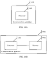
- a first terminal device includes a processor, configured to implement the method described in any one of the first aspect and the possible implementations of the first aspect.
- the terminal device may further include a memory, configured to store program instructions and data.
- the memory is coupled to the processor, and the processor may invoke and execute the program instructions stored in the memory, to implement the method described in any one of the first aspect and the possible implementations of the first aspect.
- the terminal device may further include a communications interface, and the communications interface is used by the terminal device to communicate with another device.
- the communications interface is, for example, a transceiver.
- the another device is a network device.
- the transceiver is configured to receive configuration information from the network device, where the configuration information is used to indicate a quantity M SRS of first time units that are used by the terminal device to send an SRS in one subframe, and the subframe includes a plurality of first time units.
- the processor is configured to determine, based on M SRS , a first index n ′ SRS of a first time unit used to send the SRS.
- the processor is further configured to determine, based on n ′ SRS and M a , an antenna that is used to send the SRS in a first time unit and that corresponds to n ′ SRS , where M a is a quantity of first time units that are consecutively used to send the SRS in one subframe by using a same antenna.
- the transceiver is further configured to send, by using the antenna, the SRS in the first time unit indicated by n ′ SRS .
- the processor is further configured to:
- the processor is configured to determine, in the following manner based on n ′ SRS and M a , the antenna that is used to send the SRS in the first time unit and that corresponds to n ′ SRS :
- the processor is configured to determine, in the following manner based on n ′ SRS and M a , the antenna that is used to send the SRS in the first time unit and that corresponds to n ′ SRS :
- the processor is configured to determine, in the following manner based on n ′ SRS and M a , the antenna that is used to send the SRS in the first time unit and that corresponds to n ′ SRS :
- the processor is configured to determine, in the following manner based on the quantity of transmit antennas and the quantity of receive antennas that are corresponding to the terminal device, n ′ SRS , and M a , the index of the antenna that is used to send the SRS in the first time unit and that corresponds to n ′ SRS :
- the processor is further configured to: determine, based on n ′ SRS , a subband used to send the SRS.
- a second terminal device includes a processor, configured to implement the method described in any one of the second aspect and the possible implementations of the second aspect.
- the terminal device may further include a memory, configured to store program instructions and data.
- the memory is coupled to the processor, and the processor may invoke and execute the program instructions stored in the memory, to implement the method described in any one of the second aspect and the possible implementations of the second aspect.
- the terminal device may further include a communications interface, and the communications interface is used by the terminal device to communicate with another device.
- the communications interface is, for example, a transceiver.
- the another device is a network device.
- the transceiver is configured to receive configuration information from the network device, where the configuration information is used to indicate the terminal device to perform frequency hopping within P subbands, and P is a positive integer.
- the transceiver is further configured to send an SRS to the network device in a frequency hopping manner within the P subbands, where the terminal device traverses all of the P subbands when sending the SRS in P first time units, and the terminal device traverses all transmit antennas of the terminal device when sending the SRS in the P first time units; and the processor included in the terminal device determines, based on the following formula, an index of an antenna used to send the SRS in the P first time units, where
- the first time unit is one symbol or H consecutive symbols, and H is an integer greater than or equal to 2.
- a first network device includes a processor, configured to implement the method described in any one of the third aspect and the possible implementations of the third aspect.
- the terminal device may further include a memory, configured to store program instructions and data.
- the memory is coupled to the processor, and the processor may invoke and execute the program instructions stored in the memory, to implement the method described in any one of the third aspect and the possible implementations of the third aspect.
- the network device may further include a communications interface, and the communications interface is used by the network device to communicate with another device. For example, if the network device is an independent device, the communications interface is, for example, a transceiver.
- the another device is a terminal device.
- the transceiver is configured to send configuration information to the terminal device, where the configuration information is used to indicate a quantity M SRS of first time units that are used by the terminal device to send an SRS in one subframe, and the subframe includes a plurality of first time units.
- the processor is configured to determine, based on M SRS , a first index n ′ SRS of a first time unit used to send the SRS.
- the processor is further configured to determine, based on n ′ SRS and M a , an antenna that is used to send the SRS in a first time unit and that corresponds to n ′ SRS , where M a is a quantity of first time units that are consecutively used to send the SRS in one subframe by using a same antenna.
- the transceiver is further configured to receive, by using the antenna, the SRS in the first time unit indicated by n ′ SRS .
- the processor is further configured to:
- the processor is configured to determine, in the following manner based on n ′ SRS and M a , the antenna that is used to send the SRS in the first time unit and that corresponds to n ′ SRS :
- the processor is configured to determine, in the following manner based on n ′ SRS and M a , the antenna that is used to send the SRS in the first time unit and that corresponds to n ′ SRS :
- the processor is configured to determine, in the following manner based on n ′ SRS and M a , the antenna that is used to send the SRS in the first time unit and that corresponds to n ′ SRS :
- the processor is configured to determine, in the following manner based on the quantity of transmit antennas and the quantity of receive antennas that are corresponding to the terminal device, n ′ SRS , and M a , the index of the antenna that is used to send the SRS in the first time unit and that corresponds to n ′ SRS :
- the processor is further configured to: determine, based on n ′ SRS , a subband used to send the SRS.
- a second network device includes a processor, configured to implement the method described in any one of the fourth aspect and the possible implementations of the fourth aspect.
- the terminal device may further include a memory, configured to store program instructions and data.
- the memory is coupled to the processor, and the processor may invoke and execute the program instructions stored in the memory, to implement the method described in any one of the fourth aspect and the possible implementations of the fourth aspect.
- the network device may further include a communications interface, and the communications interface is used by the network device to communicate with another device.
- the communications interface is, for example, a transceiver.
- the another device is a terminal device.
- the transceiver is configured to send configuration information to the terminal device, where the configuration information is used to indicate the terminal device to perform frequency hopping within P subbands, and P is a positive integer.
- the transceiver is further configured to receive an SRS from the terminal device in a frequency hopping manner within the P subbands, where the network device traverses all of the P subbands when receiving the SRS in P first time units, and the network device traverses all transmit antennas of the terminal device when receiving the SRS in the P first time units; and the processor included in the network device determines, based on the following formula, an index of an antenna used to receive the SRS in the P first time units, where
- the first time unit is one symbol or H consecutive symbols, and H is an integer greater than or equal to 2.
- a third terminal device may be an independent device or a chip disposed in a device.
- a function of the terminal device may be implemented by hardware, or may be implemented by hardware executing corresponding software.
- the hardware or the software includes one or more modules (or units) corresponding to the foregoing function.
- a specific structure of the terminal device may include a processing module and a transceiver module.
- the processing module and the transceiver module may perform corresponding functions in the method provided in any one of the first aspect and the possible implementations of the first aspect.
- the processing module may perform a function performed by the processor in any one of the fifth aspect and the possible implementations of the fifth aspect
- the transceiver module may perform a function performed by the transceiver in any one of the fifth aspect and the possible implementations of the fifth aspect.
- a fourth terminal device is provided.
- the terminal device may be an independent device or a chip disposed in a device.
- a function of the terminal device may be implemented by hardware, or may be implemented by hardware executing corresponding software.
- the hardware or the software includes one or more modules (or units) corresponding to the foregoing function.
- a specific structure of the terminal device may include a processing module and a transceiver module.
- the processing module and the transceiver module may perform corresponding functions in the method provided in any one of the second aspect and the possible implementations of the second aspect.
- the processing module may perform a function performed by the processor in any one of the sixth aspect and the possible implementations of the sixth aspect
- the transceiver module may perform a function performed by the transceiver in any one of the sixth aspect and the possible implementations of the sixth aspect.
- a third network device may be an independent device or a chip disposed in a device.
- a function of the network device may be implemented by hardware, or may be implemented by hardware executing corresponding software.
- the hardware or the software includes one or more modules (or units) corresponding to the foregoing function.
- a specific structure of the network device may include a processing module and a transceiver module.
- the processing module and the transceiver module may perform corresponding functions in the method provided in any one of the third aspect and the possible implementations of the third aspect.
- the processing module may perform a function performed by the processor in any one of the seventh aspect and the possible implementations of the seventh aspect
- the transceiver module may perform a function performed by the transceiver in any one of the seventh aspect and the possible implementations of the seventh aspect.
- a fourth network device is provided.
- the network device may be an independent device or a chip disposed in a device.
- a function of the network device may be implemented by hardware, or may be implemented by hardware executing corresponding software.
- the hardware or the software includes one or more modules (or units) corresponding to the foregoing function.
- a specific structure of the network device may include a processing module and a transceiver module.
- the processing module and the transceiver module may perform corresponding functions in the method provided in any one of the fourth aspect and the possible implementations of the fourth aspect.
- the processing module may perform a function performed by the processor in any one of the eighth aspect and the possible implementations of the eighth aspect
- the transceiver module may perform a function performed by the transceiver in any one of the eighth aspect and the possible implementations of the eighth aspect.
- a computer-readable storage medium including instructions.
- the instructions When the instructions are run on a computer, the computer is enabled to perform the method in any one of the first aspect and the possible implementations of the first aspect.
- a computer-readable storage medium including instructions.
- the instructions When the instructions are run on a computer, the computer is enabled to perform the method in any one of the second aspect and the possible implementations of the second aspect.
- a computer-readable storage medium including instructions.
- the instructions When the instructions are run on a computer, the computer is enabled to perform the method in any one of the third aspect and the possible implementations of the third aspect.
- a computer-readable storage medium including instructions.
- the instructions When the instructions are run on a computer, the computer is enabled to perform the method in any one of the fourth aspect and the possible implementations of the fourth aspect.
- a computer program product including instructions.
- the computer program product stores the instructions.
- the computer is enabled to perform the method in any one of the first aspect and the possible designs of the first aspect.
- a computer program product including instructions is provided.
- the computer program product stores the instructions.
- the computer is enabled to perform the method in any one of the second aspect and the possible designs of the second aspect.
- a computer program product including instructions is provided.
- the computer program product stores the instructions.
- the computer is enabled to perform the method in any one of the third aspect and the possible designs of the third aspect.
- a computer program product including instructions is provided.
- the computer program product stores the instructions.
- the computer is enabled to perform the method in any one of the fourth aspect and the possible designs of the fourth aspect.
- a fifth terminal device may be an independent device or a chip disposed in a device.
- the terminal device includes: a memory, configured to store computer executable program code; and a processor, where the processor is coupled to the memory.
- the program code stored in the memory includes instructions, and when the processor executes the instructions, a sixth communications apparatus is enabled to perform the method in any one of the first aspect and the possible implementations of the first aspect.
- the terminal device may further include a communications interface.
- the communications interface may be a transceiver in the terminal device, for example, a radio frequency transceiver component in a device; or if the terminal device is a chip disposed in a device, the communications interface may be an input/output interface of the chip, for example, an input/output pin.
- the communications interface may be connected to the radio frequency transceiver component in the device in which the terminal device is located, to implement information receiving and sending by using the radio frequency transceiver component.
- a sixth terminal device may be an independent device or a chip disposed in a device.
- the terminal device includes: a memory, configured to store computer executable program code; and a processor, where the processor is coupled to the memory.
- the program code stored in the memory includes instructions, and when the processor executes the instructions, a sixth communications apparatus is enabled to perform the method in any one of the second aspect and the possible implementations of the second aspect.
- the terminal device may further include a communications interface.
- the communications interface may be a transceiver in the terminal device, for example, a radio frequency transceiver component in a device; or if the terminal device is a chip disposed in a device, the communications interface may be an input/output interface of the chip, for example, an input/output pin.
- the communications interface may be connected to the radio frequency transceiver component in the device in which the terminal device is located, to implement information receiving and sending by using the radio frequency transceiver component.
- a fifth network device may be an independent device or a chip disposed in a device.
- the network device includes: a memory, configured to store computer executable program code; and a processor, where the processor is coupled to the memory.
- the program code stored in the memory includes instructions, and when the processor executes the instructions, a sixth communications apparatus is enabled to perform the method in any one of the third aspect and the possible implementations of the third aspect.
- the network device may further include a communications interface.
- the communications interface may be a transceiver in the network device, for example, a radio frequency transceiver component in a device; or if the network device is a chip disposed in a device, the communications interface may be an input/output interface of the chip, for example, an input/output pin.
- the communications interface may be connected to the radio frequency transceiver component in the device in which the network device is located, to implement information receiving and sending by using the radio frequency transceiver component.
- a sixth network device may be an independent device or a chip disposed in a device.
- the network device includes: a memory, configured to store computer executable program code; and a processor, where the processor is coupled to the memory.
- the program code stored in the memory includes instructions, and when the processor executes the instructions, a sixth communications apparatus is enabled to perform the method in any one of the fourth aspect and the possible implementations of the fourth aspect.
- the network device may further include a communications interface.
- the communications interface may be a transceiver in the network device, for example, a radio frequency transceiver component in a device; or if the network device is a chip disposed in a device, the communications interface may be an input/output interface of the chip, for example, an input/output pin.
- the communications interface may be connected to the radio frequency transceiver component in the device in which the network device is located, to implement information receiving and sending by using the radio frequency transceiver component.
- a first communications system includes the terminal device in any one of the fifth aspect and the possible implementations of the fifth aspect, the terminal device in any one of the ninth aspect and the possible implementations of the ninth aspect, or the terminal device in the twenty-first aspect, and includes the network device in any one of the seventh aspect and the possible implementations of the seventh aspect, the network device in any one of the eleventh aspect and the possible implementations of the eleventh aspect, or the network device in the twenty-third aspect.
- a second communications system includes the terminal device in any one of the sixth aspect and the possible implementations of the sixth aspect, the terminal device in any one of the tenth aspect and the possible implementations of the tenth aspect, or the terminal device in the twenty-second aspect, and includes the network device in any one of the eighth aspect and the possible implementations of the eighth aspect, the network device in any one of the twelfth aspect and the possible implementations of the twelfth aspect, or the network device in the twenty-fourth aspect.
- a manner of determining an antenna for sending an SRS is provided.
- a case in which one subframe includes a plurality of first time units is considered by using M SRS and a case in which one antenna is enabled to implement continuous sending as much as possible is also considered by using M a , so that a same antenna can be enabled to implement continuous sending in one subframe as much as possible, thereby minimizing an antenna switching process.
- ordinal terms such as "first" and "second” mentioned in the embodiments of this application are used to distinguish between a plurality of objects, and are not intended to limit a sequence, a time sequence, a priority, or an importance degree of the plurality of objects.
- a first time unit and a second time unit are merely intended to distinguish between different time domain resources, but are not intended to limit a priority, a length, a time domain sequence, an importance degree, or the like of the two time domain resources.
- a multiple-input multiple-output (multiple input and multiple output, MIMO) technology is widely used in an LTE system.
- MIMO multiple input and multiple output
- the network device may simultaneously send a plurality of parallel data streams to the terminal device.
- an uplink channel and a downlink channel have reciprocity.
- the terminal device sends an SRS in an uplink, and the network device may estimate an uplink channel by using the SRS, and may obtain a downlink beamforming weight value based on the uplink channel.
- a quantity of receive antennas of the terminal device is greater than a quantity of transmit antennas because each transmit antenna of the terminal device needs to be connected to one power amplifier (power amplifier, PA). Costs of the power amplifier are relatively high, and therefore only one or two PAs are usually configured for the terminal device. Therefore, the quantity of receive antennas of the terminal device is greater than the quantity of transmit antennas. In this case, the uplink channel and a downlink channel that are estimated by the network device based on the SRS are no longer symmetrical.
- antenna selection is defined in an existing LTE protocol.
- a link between a PA and an antenna in the terminal device may be dynamically changed, and the terminal device may be capable of dynamically adjusting an antenna port for sending an uplink signal.
- the terminal device supports a dynamic link between two antennas for one PA in the uplink. This scenario is referred to as 1T2R.
- 1T2R may also be understood as that the terminal device has two antennas and sends a signal by using one of the antennas at a same moment.
- LTE release 15 Rel-15
- antenna selection for 1T4R and 2T4R is already supported.
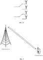
- 1T4R refer to FIG. 2B .
- 2T4R refer to FIG. 2C .
- 1T4R may also be understood that the terminal device has four antennas and sends a signal by using one of the antennas at a same moment, and 2T4R may also be understood that the terminal device has four antennas and sends a signal by using two of the antennas at a same moment.
- the SRS may be sent on the last symbol of an uplink subframe. As shown in FIG. 1 , the SRS is sent on a symbol shown in a part marked with slashes in FIG. 1 .
- a formula for antenna selection is defined in an LTE protocol. Based on the formula, the network device and the terminal device may determine an antenna used to send the SRS.
- a terminal device may determine, based on a quantity M SRS of first time units that are used by the terminal device to send an SRS in one uplink subframe, a first index n ′ SRS of a first time unit used to send the SRS, and then may determine, based on n ′ SRS and a quantity M a of first time units that are consecutively used to send the SRS in one subframe by using a same antenna, an antenna that is used to send the SRS in a first time unit and that corresponds to n ′ SRS .
- the technical solutions provided in the embodiments of this application may be applied to the LTE system, or a next-generation mobile communications system or another similar communications system. This is not specifically limited.
- FIG. 3 includes a network device and a terminal device, and the terminal device is connected to one network device.
- the network device may serve a plurality of terminal devices. All or some of the plurality of terminal devices may determine, in a manner provided in the embodiments of this application, an antenna used to send an SRS.
- the network device in FIG. 3 is, for example, an access network device such as a base station.
- the access network device corresponds to different devices in different systems.
- the access network device corresponds to an eNB in a 4th generation (the 4 th generation, 4G) system, and corresponds to a 5G access network device in a 5G system, for example, a gNB.
- FIG. 4 is a flowchart of the method.
- the method is applied to the network architecture shown in FIG. 3 .
- the method may be performed by two communications apparatuses.
- the two communications apparatuses are, for example, a first communications apparatus and a second communications apparatus.
- the first communications apparatus may be a network device or a communications apparatus that can support a network device in implementing a function required by the method, or the first communications apparatus may be a terminal device or a communications apparatus that can support a terminal device in implementing a function required by the method.
- the first communications apparatus may be another communications apparatus, for example, a chip system. The same is true for the second communications apparatus.
- the second communications apparatus may be a network device or a communications apparatus that can support a network device in implementing a function required by the method, or the second communications apparatus may be a terminal device or a communications apparatus that can support a terminal device in implementing a function required by the method.
- the second communications apparatus may be another communications apparatus, for example, a chip system.
- implementations of the first communications apparatus and the second communications apparatus are not limited.
- the first communications apparatus may be a network device
- the second communications apparatus is a terminal device, or both the first communications apparatus and the second communications apparatus are network devices, or both the first communications apparatus and the second communications apparatus are terminal devices, or the first communications apparatus is a network device, and the second communications apparatus is a communications apparatus that can support a terminal device in implementing a function required by the method.
- the network device is, for example, a base station.
- the following uses an example in which the method is performed by a network device and a terminal device, that is, an example in which the first communications apparatus is a network device and the second communications apparatus is a terminal device.
- the network device described below may be a network device in the network architecture shown in FIG. 3
- the terminal device described below may be a terminal device in the network architecture shown in FIG. 3 .
- a network device sends configuration information to a terminal device, and the terminal device receives the configuration information from the network device, where the configuration information is used to indicate a quantity M SRS of first time units that are used by the terminal device to send an SRS in one subframe, and the subframe includes a plurality of first time units.
- the configuration information may be used to indicate a quantity of first time units that are used by the terminal device to send an SRS in one second time unit, and the second time unit may include a plurality of first time units.
- the second time unit is, for example, a subframe (subframe) or a slot (slot). In the descriptions of this specification, for example, the second time unit is a subframe.
- the first time unit may be one symbol or H consecutive symbols, and H is an integer greater than or equal to 2.
- the first time unit is one symbol.
- a plurality of symbols may be used to send the SRS in one subframe, and may be predefined in a protocol.
- a quantity of symbols used to send the SRS in one subframe may be configured by the network device.
- the protocol specifies that four symbols may be used to send the SRS in one subframe.
- a quantity, configured by the network device for each terminal device, of symbols that can be used to send the SRS in one subframe may be less than or equal to 4.
- the network device may determine a quantity of first time units that are used by the terminal device to send the SRS in one subframe, and notify the terminal device of the quantity by using the configuration information.
- the terminal device may determine the quantity of first time units that may be used to send the SRS in one subframe.
- the quantity of first time units that are used by the terminal device to send the SRS in one subframe is, for example, represented by M SRS .
- the terminal device determines, based on M SRS , a first index n ′ SRS of a first time unit used to send the SRS.
- the terminal device may determine, based on M SRS , the first index of the first time unit used to send the SRS.
- the first index is represented by n ′ SRS .
- First time units used to send the SRS may be located in one or more subframes, and n ′ SRS may be used to uniformly index the first time units located in the one or more subframes.
- the "first index" in this specification is a relative index, and is not an index of a corresponding time unit in a subframe or in a radio frame.
- the first index of the first time unit herein is a relative index of the first time unit, and is not an index of the first time unit in a subframe or in a radio frame.
- the terminal device sends the SRS in two subframes, and sends the SRS in each subframe by using four symbols.
- first indexes of symbols used to send the SRS may be 1 to 8 (or 0 to 7).
- the first index means that only symbols used to send the SRS in each subframe are uniformly indexed, and symbols that are not used to send the SRS in the subframe are not included in an index range.
- symbols used to send the SRS may be the last four symbols in the subframe, and indexes of the last four symbols in one subframe should be 8 to 11. For example, if the subframe is the first subframe used to send the SRS, first indexes of the four symbols are 1 to 4 (or 0 to 3).
- T SRS represents an SRS transmission periodicity configured by the network device for the terminal device
- T offset represents a position of a subframe that is used to send the SRS in the periodicity T SRS configured by the network device for the terminal device
- N SP represents a quantity of downlink-to-uplink switching points in a radio frame in which the SRS is located
- n f represents a frame number of the radio frame in which the SRS is located
- n s represents a slot number in the radio frame in which the SRS is located
- n s 0, 1, ..., 19
- m represents a first index of a first time unit that is allocated to the terminal device to transmit the SRS in one subframe
- m 0, 1, ..., M SRS -1
- ⁇ ⁇ represents rounding down.
- T SRS is 5 ms.
- the terminal device sends the SRS in the last four symbols in a subframe 2 of each radio frame.
- n ′ SRS refer to FIG. 5 .
- 0 to 3, 4 to 7, and the like in FIG. 5 represent n ′ SRS of symbols.
- 0 to 3 represent n ′ SRS of four symbols.
- FIG. 5 shows only a part of the radio frame, that is, only a part of values of n ′ SRS are shown, and there are no more examples.
- FIG. 5 is merely an example in which the terminal device sends the SRS in two subframes of one radio frame.
- the terminal device may alternatively send the SRS in one subframe of one radio frame, or may send the SRS in three or more subframes of one radio frame.
- n SRS is further used to indicate a first index of a subframe used to send the SRS.
- the first index of the subframe is not an index of the subframe in a radio frame but is used to uniformly index subframes used to send the SRS, and a subframe that is not used to send the SRS is not included in an index range.
- n SRS ⁇ 2 N SP n f + 2 N SP ⁇ 1 ⁇ n s 10 ⁇ + ⁇ T offset T offset _ max ⁇
- frame structure type 2 with an SRS period of 2 ms ⁇ n f ⁇ 10 + ⁇ n s 2 ⁇ / T SRS ⁇ , other cases
- n ′ SRS may be determined in another manner, provided that M SRS is considered during the determining of n ′ SRS .
- the terminal device determines, based on n ′ SRS and M a , an antenna that is used to send the SRS in a first time unit and that corresponds to n ′ SRS , where M a is a quantity of first time units that are consecutively used to send the SRS in one subframe by using a same antenna.
- the terminal device requires a specific time to switch an antenna used to send the SRS. Therefore, frequent antenna switching in one subframe wastes a lot of time-frequency resources. For example, four symbols in one subframe are allocated to the terminal device to send the SRS. If the terminal device performs antenna switching on each symbol, a lot of antenna switching preparation time is actually wasted. For this, refer to FIG. 6A .
- the terminal device may send an SRS in one subframe by using the last four symbols of the subframe. It may be learned that, on the four symbols, the terminal device frequently switches an antenna used to send the SRS. It should be noted that the terminal device cannot send a signal within an antenna switching preparation time.
- a same antenna may be used to send an SRS on several consecutive symbols.
- the quantity of first time units that are consecutively used to send the SRS in one subframe by using the same antenna also needs to be considered. Therefore, when the antenna used to send the SRS in the first time unit is being determined, the quantity of first time units that are consecutively used to send the SRS in one subframe by using the same antenna also needs to be considered in addition to n ′ SRS .
- the quantity of first time units that are consecutively used to send the SRS in one subframe by using the same antenna is, for example, represented by M a .
- the determined antenna used to send the SRS in the first time unit may correspond to n ′ SRS because n ′ SRS is the first index of the first time unit used to send the SRS.
- the terminal device may further perform frequency hopping in a process of sending the SRS.
- a determining manner may be related to whether frequency hopping is performed. This antenna determining manner may be applicable to both manner 1 and manner 2.
- the terminal device may determine, based on a quantity of transmit antennas and a quantity of receive antennas that are corresponding to the terminal device, n ′ SRS , and M a if no frequency hopping is configured for the SRS, an index of the antenna that is used to send the SRS in the first time unit and that corresponds to n ′ SRS .
- the terminal device may determine, based on a quantity of subbands occupied by the SRS in a frequency hopping process, n ′ SRS , , and M a if frequency hopping is configured for the SRS, an index of the antenna that is used to send the SRS in the first time unit and that corresponds to n ′ SRS .
- a unified manner may be used to determine the antenna that is used to send the SRS in the first time unit and that corresponds to n ′ SRS .
- the terminal device may determine, based on a quantity of transmit antennas and a quantity of receive antennas that are corresponding to the terminal device, n ′ SRS , and M a , an index of the antenna that is used to send the SRS in the first time unit and that corresponds to n ′ SRS .
- This antenna determining manner may also be applicable to both manner 1 and manner 2.
- a quantity of antennas of the terminal device is further related. Therefore, in the process of determining the antenna, the quantity of antennas of the terminal device is further considered, or in other words, the quantity of transmit antennas and the quantity of receive antennas of the terminal device are considered.
- a determining manner is related to whether frequency hopping is performed.
- the terminal device may determine, based on the quantity of transmit antennas and the quantity of receive antennas that are corresponding to the terminal device, n ′ SRS , and M a if no frequency hopping is configured for the SRS, the index of the antenna that is used to send the SRS in the first time unit and that corresponds to n ′ SRS .
- a ( n SRS_ant ) represents the index of the antenna that is used to send the SRS in the first time unit and that corresponds to n ′ SRS
- n SRS _ ant ⁇ n ′ SRS / M a ⁇ .
- ⁇ may be understood as a quantity of antenna pairs (pair) in the terminal device.
- antenna ports for simultaneously sending an SRS may be ⁇ 0, 1 ⁇ or ⁇ 2, 3 ⁇ , or may be ⁇ 0, 1 ⁇ , ⁇ 0, 2 ⁇ , or ⁇ 0, 3 ⁇ .
- a determining manner is related to whether frequency hopping is performed.
- the terminal device may determine, based on the quantity of subbands occupied by the SRS in the frequency hopping process, n ′ SRS , and M a if frequency hopping is configured for the SRS, the index of the antenna that is used to send the SRS in the first time unit and that corresponds to n ′ SRS .
- a ( n SRS_ant ) represents the index of the antenna that is used to send the SRS in the first time unit and that corresponds to n ′ SRS
- n SRS _ ant ⁇ n ′ SRS / M a ⁇
- K represents the quantity of subbands occupied by the SRS in the frequency hopping process
- N1 and N2 are quantities determined based on an SRS bandwidth configuration parameter C SRS , and a correspondence between C SRS , a quantity m SRS,b of resource blocks (resource block, RB) included in SRS bandwidth, and N b is shown in Table 1 to Table 4.
- the terminal device may determine, based on the quantity of transmit antennas and the quantity of receive antennas that are corresponding to the terminal device, n ′ SRS , and M a regardless of whether frequency hopping is configured for the SRS, the index of the antenna that is used to send the SRS in the first time unit and that corresponds to n ′ SRS .
- the antenna selection mode may enable the LTE system and an NR system to have a same antenna selection manner, thereby facilitating simultaneous transmission of an SRS in the LTE system and the NR system.
- a ( n SRS _ ant ) represents the index of the antenna that is used to send the SRS in the first time unit and that corresponds to n ′ SRS
- n SRS _ ant ⁇ n ′ SRS / M a ⁇ . It may be learned that formula 10 is the same as formula 4.
- the foregoing describes how the terminal device determines the antenna that is used to send the SRS in the first time unit and that corresponds to n ′ SRS .
- the foregoing also describes a case in which the terminal device may further perform frequency hopping when sending the SRS.
- a position of a subband used to send the SRS needs to be further determined.
- the terminal device may determine, based on n ′ SRS , the subband used to send the SRS.
- b hop is determined based on SRS-hopping bandwidth ( srs-HoppingBandwidth ) delivered by the network device, b hop ⁇ 0, 1, 2, 3 ⁇ , n RRC is determined based on a periodic SRS frequency domain position (freqDomainPosition) or an aperiodic SRS frequency domain position (freqDomainPosition-ap) delivered by the network device, B SRS , N b , N b' , and M SRS,b are determined based on an SRS-bandwidth configuration (srs-BandwidthConfig) delivered by the network device, and N ant represents a quantity of antennas in the terminal device.
- srs-HoppingBandwidth SRS-hopping bandwidth
- the antenna selection mode may enable the LTE system and the NR system to have a same antenna selection manner, thereby facilitating simultaneous transmission of an SRS in the LTE system and the NR system.
- the LTE system and the NR system can also have a same frequency hopping manner by using formula 15 to determine the subband used to send the SRS.
- the terminal device sends the SRS by using the antenna in the first time unit indicated by n ′ SRS , and the network device receives the SRS from the terminal device in the first time unit indicated by n ′ SRS .
- the network device may also determine, in a manner the same as that of the terminal device, the antenna used to send the SRS, the position of the subband used to send the SRS, and the like. Details are not described again.
- the terminal device may determine, based on the quantity M SRS of first time units that are used by the terminal device to send the SRS in one subframe, the first index n ′ SRS of the first time unit used to send the SRS, and then determine, based on n ′ SRS and the quantity M a of first time units that are consecutively used to send the SRS in one subframe by using a same antenna, the antenna that is used to send the SRS in the first time unit and that corresponds to n ′ SRS . Therefore, a case in which one subframe includes a plurality of first time units is considered by using M SRS and a case in which one antenna is enabled to implement continuous sending as much as possible is also considered by using Ma .
- a manner of determining an antenna for sending an SRS is provided, and a same antenna can be enabled to implement continuous sending as much as possible. For example, a quantity of antenna switching times can be reduced in one subframe, or no antenna switching may be performed in one subframe, so that service continuity can be ensured as much as possible and power consumption caused by antenna switching of the terminal device can be reduced.
- FIG. 7 is a flowchart of the method.
- the method is applied to the network architecture shown in FIG. 3 .
- the method may be performed by two communications apparatuses.
- the two communications apparatuses are, for example, a third communications apparatus and a fourth communications apparatus.
- the third communications apparatus may be a network device or a communications apparatus that can support a network device in implementing a function required by the method, or the third communications apparatus may be a terminal device or a communications apparatus that can support a terminal device in implementing a function required by the method.
- the third communications apparatus may be another communications apparatus, for example, a chip system.
- the fourth communications apparatus may be a network device or a communications apparatus that can support a network device in implementing a function required by the method, or the fourth communications apparatus may be a terminal device or a communications apparatus that can support a terminal device in implementing a function required by the method.
- the fourth communications apparatus may be another communications apparatus, for example, a chip system.
- implementations of the third communications apparatus and the fourth communications apparatus are not limited.
- the third communications apparatus may be a network device, and the fourth communications apparatus is a terminal device, or both the third communications apparatus and the fourth communications apparatus are network devices, or both the third communications apparatus and the fourth communications apparatus are terminal devices, or the third communications apparatus is a network device, and the fourth communications apparatus is a communications apparatus that can support a terminal device in implementing a function required by the method.
- the network device is, for example, a base station.
- the following uses an example in which the method is performed by a network device and a terminal device, that is, an example in which the third communications apparatus is a network device and the fourth communications apparatus is a terminal device.
- the network device described below may be a network device in the network architecture shown in FIG. 3
- the terminal device described below may be a terminal device in the network architecture shown in FIG. 3 .
- a network device sends configuration information to a terminal device, and the terminal device receives the configuration information from the network device, where the configuration information is used to indicate the terminal device to perform frequency hopping within P subbands, and P is a positive integer.
- the terminal device sends an SRS to the network device within the P subbands in a frequency hopping manner, and the network device receives the SRS from the terminal device within the P subbands, where the terminal device traverses all of the P subbands when sending the SRS in P first time units, and the terminal device traverses all transmit antennas of the terminal device when sending the SRS in the P first time units.
- the first time unit may be one symbol or H consecutive symbols, and H is an integer greater than or equal to 2.
- the first time unit is one symbol.
- a plurality of symbols may be used to send the SRS in one subframe, and may be predefined in a protocol.
- a quantity of symbols used to send the SRS in one subframe may be configured by the network device.
- the protocol specifies that four symbols may be used to send the SRS in one subframe.
- a quantity, configured by the network device for each terminal device, of symbols that can be used to send the SRS in one subframe may be less than or equal to 4.
- the network device may determine a quantity of first time units that are used by the terminal device to send the SRS in one subframe, and notify the terminal device of the quantity by using the configuration information. Therefore, after receiving the configuration information, the terminal device may determine the quantity of first time units that may be used to send the SRS in one subframe.
- the terminal device may determine, in the following manner, an index of an antenna used to send the SRS in the P first time units:
- a ( n SRS _ ant ) represents the index of the antenna used to send the SRS
- n SRS_ant ⁇ n ′ SRS / M a ⁇ .
- a ( n SRS _ ant ) represents the index of the antenna used to send the SRS
- n SRS_ant ⁇ n ′ SRS / M a ⁇ .
- a ( n SRS_ant ) represents the index of the antenna used to send the SRS
- n SRS _ ant ⁇ n ′ SRS / M a ⁇
- ⁇ is 2 or 3.
- M a is a quantity of first time units that are consecutively used to send the SRS in one subframe by using a same antenna
- n ′ SRS is a first index of a first time unit used to send the SRS.
- T SRS represents an SRS transmission periodicity configured by the network device for the terminal device
- T offset represents a position of a subframe that is used to send the SRS in the periodicity T SRS configured by the network device for the terminal device
- N SP represents a quantity of downlink-to-uplink switching points in a radio frame in which the SRS is located
- n f represents a frame number of the radio frame in which the SRS is located
- n s represents a slot number in the radio frame in which the SRS is located
- n s 0, 1, ..., 19
- M SRS represents a quantity of first time units that are allocated to the terminal device to transmit the SRS in one subframe
- m represents a first index of a first time unit that is allocated to the terminal device to transmit the SRS in one subframe
- m 0, 1, ..., M SRS -1.
- a manner of determining n ′ SRS is not limited in this embodiment of this application.
- the terminal device may determine n ′ SRS in another manner, provided that the quantity of first time units that are allocated to the terminal device to transmit the SRS in one subframe is considered during the determining of n ′ SRS .
- formula 17 is the same as formula 12
- formula 18 is the same as formula 13
- formula 19 is the same as formula 14.
- the terminal device determines the antenna in the third antenna determining manner described in the embodiment shown in FIG. 4 .
- the terminal device traverses all of the P subbands when sending the SRS in the P first time units, and the terminal device traverses all the transmit antennas of the terminal device when sending the SRS in the P first time units.
- the terminal device uses all the transmit antennas of the terminal device when sending the SRS in the P first time units, and traverses all of the P subbands when sending the SRS in the P first time units.
- the terminal device sends the SRS on a subband 1 on the first symbol by using an antenna 0, sends the SRS on a subband 3 on the second symbol by using the antenna 0, sends the SRS on a subband 2 on the third symbol by using an antenna 1, and sends the SRS on a subband 4 on the fourth symbol by using the antenna 1. It may be learned that, the terminal device uses all the transmit antennas of the terminal device and traverse all the subbands in the process of sending the SRS.
- the P first time units belong to one subframe is merely used.
- a quantity of subframes to which the P first time units belong is not limited.
- the P first time units may belong to one subframe or a plurality of subframes.
- FIG. 7 may be further understood based on the following process.
- the terminal device may first determine, based on a quantity M SRS of first time units used to transmit the SRS in one subframe, a first index n ′ SRS of a first time unit used to send the SRS. For a manner of determining n ′ SRS , refer to formula 20. After n ′ SRS is determined, a new first index of a first time unit used to send the SRS may be determined based on n ′ SRS and a first formula.
- the determined new first index satisfies that a virtual corresponding antenna determined based on the first formula and a new index corresponding to n ′ SRS + 1 and a virtual corresponding antenna determined based on the first formula and a new index corresponding to n ′ SRS are a same antenna; or a virtual corresponding antenna determined based on the first formula and a new index corresponding to n ′ SRS ⁇ 1 and a virtual corresponding antenna determined based on the first formula and n ′ SRS are a same antenna.
- the determined new first index satisfies that the SRS is sent by using a same antenna in at least two consecutive first time units.
- the "virtual corresponding antenna" herein is actually a determined antenna.
- the determined antenna is referred to as the "virtual corresponding antenna".
- an antenna actually used by the terminal device to send the SRS is determined based on formula 17 to formula 19, and the "virtual corresponding antenna” herein is apparently not the foregoing antenna determined based on formula 17 to formula 19.
- the terminal device may determine, based on n ′ SRS and the first formula, a virtual corresponding antenna of each first time unit that is used to send the SRS in one second time unit and on which the SRS is sent, and then obtain, based on the virtual corresponding antenna of each first time unit that is used to transmit the SRS and on which the SRS is transmitted, a new index of the first time unit used to send the SRS.
- the first formula includes:
- the terminal device may determine, based on the new first index of the first time unit used to send the SRS, a subband used to send the SRS.
- n SRS _ new represents the new first index of the first time unit used to send the SRS
- N ant represents a quantity of antennas in the terminal device
- the terminal device may send the SRS in the first time unit indicated by n' SRS and on the subband used to send the SRS by using the antenna determined based on formula 17 to formula 19.
- the first time unit is one symbol.
- the terminal device first determines, based on a quantity M SRS of symbols used to transmit the SRS in one subframe, a first index n' SRS of a symbol used to send the SRS.
- FIG. 8 shows three subframes.
- first indexes n ′ SRS that are of symbols used to send the SRS and that are determined by the terminal device include 0 to 3 in the first subframe, include 4 to 7 in the second subframe, and include 8 to 11 in the third subframe.
- a virtual corresponding antenna of each symbol that is used to send the SRS in one subframe and on which the SRS is sent may be determined based on n ′ SRS and the first formula. For example, the terminal device determines that a virtual corresponding antenna of a symbol 0 included in the first subframe is an antenna 0, a virtual corresponding antenna of a symbol 1 included in the first subframe is an antenna 1, a virtual corresponding antenna of a symbol 2 included in the first subframe is an antenna 1, and a virtual corresponding antenna of a symbol 3 included in the first subframe is an antenna 0. For cases in the second subframe and the third subframe, refer to FIG. 8 . Details are not described herein.
- the two symbols corresponding to the antenna 1 are consecutive, but two symbols corresponding to the antenna 0 are not consecutive.
- a symbol corresponding to the antenna 0 may be changed.
- the symbol 3 corresponding to the antenna 0 may be changed to the symbol 1.
- a symbol corresponding to an antenna 2 is also changed.
- a symbol 1 and a symbol 2 corresponding to the antenna 2 are changed to a symbol 2 and a symbol 3. In this way, a new first index of a symbol used to send the SRS is obtained.
- FIG. 9 is a schematic diagram of a subband used by the terminal device to send an SRS.
- a vertical axis represents frequency domain, and a horizontal axis represents time domain.
- the terminal device sends the SRS on a subband 1 by using an antenna 0 on a symbol 0, sends the SRS on a subband 3 by using the antenna 0 on a symbol 1, sends the SRS on a subband 2 by using an antenna 1 on a symbol 2, and sends the SRS on a subband 4 by using the antenna 1 on a symbol 3. It may be learned that, the terminal device uses all transmit antennas of the terminal device on P symbols and traverses all subbands in the process of sending the SRS, so that the network device can obtain channel information of all uplink subbands.
- the terminal device may further determine, based on formula 17 to formula 19, the antenna used to send the SRS.
- the antenna used to send the SRS For an index of the antenna used to send the SRS, refer to the example in FIG. 8 . Taking the first subframe as an example, an antenna corresponding to the symbol 0 and the symbol 1 is the antenna 0, and an index of an antenna corresponding to the symbol 2 and the symbol 3 is the antenna 1.
- the terminal device may send the SRS after determining the antenna and the subband.
- the network device may determine, in a manner the same as that of the terminal device, the subband used to send the SRS, and determine the antenna actually used to send the SRS. Details are not described again.
- the network device can obtain channel information of all uplink subbands in a relatively short time, so that the network device can perform relatively proper scheduling on the terminal device.
- a case in which one subframe includes a plurality of first time units is considered and a case in which one antenna is enabled to implement continuous sending as much as possible is also considered by using M a , so that a quantity of antenna switching times can be reduced in one subframe, or no antenna switching may be performed in one subframe, to ensure service continuity as much as possible and reduce power consumption caused by antenna switching of the terminal device.
- FIG. 10 is a schematic structural diagram of a terminal device 1000.
- the terminal device 1000 may implement a function of the terminal device described above.
- the terminal device 1000 may be an independent device that can implement a function of the foregoing terminal device, or may be a chip disposed in a device that can implement a function of the foregoing terminal device.
- the terminal device 1000 may include a processor 1001 and a transceiver 1002. If the terminal device 1000 is the independent device, the transceiver 1002 may be a radio frequency transceiver component in the device.
- the transceiver 1002 may be a communications interface in the chip, and the communications interface may be connected to the radio frequency transceiver component in the device in which the chip is located, to implement signal receiving and sending by using the radio frequency transceiver component.
- the processor 1001 may be configured to perform S42 and S43 in the embodiment shown in FIG. 4 , and/or configured to support another process of the technology described in this specification.
- the transceiver 1002 may be configured to perform S41 and S44 in the embodiment shown in FIG. 4 , and/or configured to support another process of the technology described in this specification.
- the transceiver 1002 is configured to receive configuration information from a network device, where the configuration information is used to indicate a quantity M SRS of first time units that are used by the terminal device to send an SRS in one subframe, and the subframe includes a plurality of first time units.
- the processor 1001 is configured to determine, based on M SRS , a first index n ′ SRS of a first time unit used to send the SRS.
- the processor 1001 is further configured to determine, based on n ′ SRS and M a , an antenna that is used to send the SRS in a first time unit and that corresponds to n ′ SRS , where M a is a quantity of first time units that are consecutively used to send the SRS in one subframe by using a same antenna.
- the transceiver 1002 is further configured to send, by using the antenna, the SRS in the first time unit indicated by n ′ SRS .
- FIG. 11 is a schematic structural diagram of a network device 1100.
- the network device 1100 may implement a function of the network device described above.
- the network device 1100 may be an independent device that can implement a function of the foregoing network device, or may be a chip disposed in a device that can implement a function of the foregoing network device.
- the network device 1100 may include a processor 1101 and a transceiver 1102. If the network device 1100 is the independent device, the transceiver 1102 may be a radio frequency transceiver component in the device.
- the transceiver 1102 may be a communications interface in the chip, and the communications interface may be connected to the radio frequency transceiver component in the device in which the chip is located, to implement signal receiving and sending by using the radio frequency transceiver component.
- the processor 1101 may be configured to: generate configuration information in the embodiment shown in FIG. 4 , determine, based on M SRS , a first index n ′ SRS of a first time unit used to send an SRS, and determine, based on n ′ SRS and M a , an antenna that is used to send the SRS in a first time unit and that corresponds to n ′ SRS .
- M a is a process such as a quantity of first time units that are consecutively used to send the SRS in one subframe by using a same antenna, and/or configured to support another process of the technology described in this specification.
- the transceiver 1102 may be configured to perform S41 and S44 in the embodiment shown in FIG. 4 , and/or configured to support another process of the technology described in this specification.
- the transceiver 1102 is configured to send configuration information to a terminal device, where the configuration information is used to indicate a quantity M SRS of first time units that are used by the terminal device to send an SRS in one subframe, and the subframe includes a plurality of first time units.
- the processor 1101 is configured to determine, based on M SRS , a first index n ′ SRS of a first time unit used to send the SRS.
- the processor 1101 is further configured to determine, based on n ′ SRS and M a , an antenna that is used to send the SRS in a first time unit and that corresponds to n ′ SRS , where M a is a quantity of first time units that are consecutively used to send the SRS in one subframe by using a same antenna.
- the transceiver 1102 is further configured to receive, by using the antenna, the SRS in the first time unit indicated by n ′ SRS .
- FIG. 12 is a schematic structural diagram of a terminal device 1200.
- the terminal device 1200 may implement a function of the terminal device described above.
- the terminal device 1200 may be an independent device that can implement a function of the foregoing terminal device, or may be a chip disposed in a device that can implement a function of the foregoing terminal device.
- the terminal device 1200 may include a processor 1201 and a transceiver 1202. If the terminal device 1200 is the independent device, the transceiver 1202 may be a radio frequency transceiver component in the device.
- the transceiver 1202 may be a communications interface in the chip, and the communications interface may be connected to the radio frequency transceiver component in the device in which the chip is located, to implement signal receiving and sending by using the radio frequency transceiver component.
- the processor 1201 may be configured to perform a process such as determining an antenna and a subband used to send an SRS in the embodiment shown in FIG. 7 , and/or configured to support another process of the technology described in this specification.
- the transceiver 1202 may be configured to perform S71 and S72 in the embodiment shown in FIG. 7 , and/or configured to support another process of the technology described in this specification.
- the transceiver 1202 is configured to receive configuration information from a network device, where the configuration information is used to indicate the terminal device 1200 to perform frequency hopping within P subbands, and P is a positive integer.
- the transceiver 1202 is further configured to send an SRS to the network device in a frequency hopping manner within the P subbands, where the terminal device traverses all of the P subbands when sending the SRS in P first time units, and the terminal device 1200 traverses all transmit antennas of the terminal device 1200 when sending the SRS in the P first time units; and the processor 1201 determines, based on the following formula, an index of an antenna used to send the SRS in the P first time units, where
- the terminal device 1200 shown in FIG. 12 and the terminal device 1000 shown in FIG. 10 may be a same communications apparatus, or may be different communications apparatuses.
- FIG. 13 is a schematic structural diagram of a network device 1300.
- the network device 1300 may implement a function of the network device described above.
- the network device 1300 may be an independent device that can implement a function of the foregoing network device, or may be a chip disposed in a device that can implement a function of the foregoing network device.
- the network device 1300 may include a processor 1301 and a transceiver 1302. If the network device 1300 is the independent device, the transceiver 1302 may be a radio frequency transceiver component in the device.
- the transceiver 1302 may be a communications interface in the chip, and the communications interface may be connected to the radio frequency transceiver component in the device in which the chip is located, to implement signal receiving and sending by using the radio frequency transceiver component.
- the processor 1301 may be configured to perform a process such as determining an antenna and a subband used to send an SRS in the embodiment shown in FIG. 7 , and/or configured to support another process of the technology described in this specification.
- the transceiver 1302 may be configured to perform S71 and S72 in the embodiment shown in FIG. 7 , and/or configured to support another process of the technology described in this specification.
- the transceiver 1302 is configured to send configuration information to a terminal device, where the configuration information is used to indicate the terminal device to perform frequency hopping within P subbands, and P is a positive integer.
- the transceiver 1302 is further configured to receive an SRS from the terminal device in a frequency hopping manner within the P subbands, where the network device 1300 traverses all of the P subbands when receiving the SRS in P first time units, and the network device 1300 traverses all transmit antennas of the terminal device when receiving the SRS in the P first time units; and the processor 1301 determines, based on the following formula, an index of an antenna used to receive the SRS in the P first time units, where
- a person skilled in the art may figure out that when the terminal device 1000, the network device 1100, the terminal device 1200, or the network device 1300 is a chip, the terminal device 1000, the network device 1100, the terminal device 1200, or the network device 1300 may be further implemented by using a structure of a communications apparatus 1400 shown in FIG. 14A .
- the communications apparatus 1400 may implement a function of the terminal device or the network device described above.
- the communications apparatus 1400 may include a processor 1401.
- the processor 1401 may be configured to: generate configuration information in the embodiment shown in FIG. 4 , determine, based on M SRS , a first index n ′ SRS of a first time unit used to send an SRS, and determine, based on n ′ SRS and M a , an antenna that is used to send the SRS in a first time unit and that corresponds to n ′ SRS .
- M a is a process such as a quantity of first time units that are consecutively used to send the SRS in one subframe by using a same antenna, and/or configured to support another process of the technology described in this specification.
- the processor 1401 may be configured to perform S42 and S43 in the embodiment shown in FIG. 4 , and/or configured to support another process of the technology described in this specification.
- the processor 1401 may be configured to perform a process such as determining an antenna and a subband used to send an SRS in the embodiment shown in FIG. 7 , and/or configured to support another process of the technology described in this specification.
- the processor 1401 may be configured to perform a process such as determining an antenna and a subband used to send an SRS in the embodiment shown in FIG. 7 , and/or configured to support another process of the technology described in this specification.
- the communications apparatus 1400 may be implemented by using a field programmable gate array (field-programmable gate array, FPGA), an application-specific integrated circuit (application specific integrated circuit, ASIC), a system on chip (system on chip, SoC), a central processing unit (central processor unit, CPU), a network processor (network processor, NP), a digital signal processing circuit (digital signal processor, DSP), a micro controller unit (micro controller unit, MCU), a programmable logic device (programmable logic device, PLD), or another integrated chip.
- the communications apparatus 1400 may be disposed in the network device or the terminal device in the embodiments of this application, so that the network device or the terminal device implements the method provided in the embodiments of this application.
- the communications apparatus 1400 may include a transceiver component, configured to communicate with another device.
- the transceiver component may be configured to perform S41 and S44 in the embodiment shown in FIG. 4 , and/or configured to support another process of the technology described in this specification.
- the transceiver component may be configured to perform S71 and S72 in the embodiment shown in FIG. 7 , and/or configured to support another process of the technology described in this specification.
- the transceiver component is a communications interface.
- the communications interface may be a transceiver in the network device or the terminal device, for example, a transceiver 402 or a transceiver 502.
- the transceiver is, for example, a radio frequency transceiver component in the network device or the terminal device.
- the communications interface may be an input/output interface of the chip, for example, an input/output pin.
- the communications apparatus 1400 may further include a memory 1402.
- the memory 1402 is configured to store computer programs or instructions
- the processor 1401 is configured to decode and execute the computer programs or the instructions.
- these computer programs or instructions may include function programs of the network device or the terminal device.
- the network device may be enabled to implement functions of the network device in the method provided in the embodiment shown in FIG. 4 or the embodiment shown in FIG. 7 in the embodiments of this application.
- the terminal device may be enabled to implement functions of the terminal device in the method provided in the embodiment shown in FIG. 4 or the embodiment shown in FIG. 7 in the embodiments of this application.
- these function programs of the network device or the terminal device are stored in an external memory of the communications apparatus 1400.
- the memory 1402 temporarily stores some or all content of the function programs of the network device.
- the memory 1402 temporarily stores some or all content of the function programs of the terminal device.
- these function programs of the network device or the terminal device are set to be stored in the memory 1402 in the communications apparatus 1400.
- the communications apparatus 1400 may be disposed in the network device in the embodiments of this application.
- the communications apparatus 1400 may be disposed in the terminal device in the embodiments of this application.
- some content of these function programs of the network device is stored in an external memory of the communications apparatus 1400, and the other content of these function programs of the network device is stored in the memory 1402 in the communications apparatus 1400.
- some content of these function programs of the terminal device is stored in an external memory of the communications apparatus 1400, and the other content of these function programs of the terminal device is stored in the memory 1402 in the communications apparatus 1400.
- the terminal device 1000, the network device 1100, the terminal device 1200, the network device 1300, and the communications apparatus 1400 may be presented in a form in which function modules are obtained through division based on corresponding functions, or may be presented in a form in which function modules are obtained through division in an integrated manner.
- the "module” herein may be an ASIC, a processor and a memory that execute one or more software or firmware programs, an integrated logic circuit, and/or another component that can provide the foregoing functions.
- the terminal device 1000 provided in the embodiment shown in FIG. 10 may alternatively be implemented in another form.
- the communications apparatus includes a processing unit and a transceiver unit.
- the processing unit may be implemented by using the processor 1001, and the transceiver unit may be implemented by using the transceiver 1002.
- the processing unit may be configured to perform S42 and S43 in the embodiment shown in FIG. 4 , and/or configured to support another process of the technology described in this specification.
- the transceiver unit may be configured to perform S41 and S44 in the embodiment shown in FIG. 4 , and/or configured to support another process of the technology described in this specification.
- the transceiver unit is configured to receive configuration information from a network device, where the configuration information is used to indicate a quantity M SRS of first time units that are used by the terminal device to send an SRS in one subframe, and the subframe includes a plurality of first time units.
- the processing unit is configured to determine, based on M SRS , a first index n ′ SRS of a first time unit used to send the SRS.
- the processing unit is further configured to determine, based on n ′ SRS and M a , an antenna that is used to send the SRS in a first time unit and that corresponds to n ′ SRS , where M a is a quantity of first time units that are consecutively used to send the SRS in one subframe by using a same antenna.
- the transceiver unit is further configured to send, by using the antenna, the SRS in the first time unit indicated by n ′ SRS .
- the network device 1100 provided in the embodiment shown in FIG. 11 may alternatively be implemented in another form.
- the communications apparatus includes a processing unit and a transceiver unit.
- the processing unit may be implemented by using the processor 1101, and the transceiver unit may be implemented by using the transceiver 1102.
- the processing unit may be configured to: generate configuration information in the embodiment shown in FIG. 4 , determine, based on M SRS , a first index n ′ SRS of a first time unit used to send an SRS, and determine, based on n ′ SRS and M a , an antenna that is used to send the SRS in a first time unit and that corresponds to n ′ SRS .
- M a is a process such as a quantity of first time units that are consecutively used to send the SRS in one subframe by using a same antenna, and/or configured to support another process of the technology described in this specification.
- the transceiver unit may be configured to perform S41 and S44 in the embodiment shown in FIG. 4 , and/or configured to support another process of the technology described in this specification.
- the transceiver unit is configured to send configuration information to a terminal device, where the configuration information is used to indicate a quantity M SRS of first time units that are used by the terminal device to send an SRS in one subframe, and the subframe includes a plurality of first time units.
- the processing unit is configured to determine, based on M SRS , a first index n ′ SRS of a first time unit used to send the SRS.
- the processing unit is further configured to determine, based on n ′ SRS and M a , an antenna that is used to send the SRS in a first time unit and that corresponds to n ′ SRS , where M a is a quantity of first time units that are consecutively used to send the SRS in one subframe by using a same antenna.
- the transceiver unit is further configured to receive, by using the antenna, the SRS in the first time unit indicated by n ′ SRS .
- the terminal device 1200 provided in the embodiment shown in FIG. 12 may alternatively be implemented in another form.
- the communications apparatus includes a processing unit and a transceiver unit.
- the processing unit may be implemented by using the processor 1201, and the transceiver unit may be implemented by using the transceiver 1202.
- the processing unit may be configured to perform a process such as determining an antenna and a subband used to send an SRS in the embodiment shown in FIG. 7 , and/or configured to support another process of the technology described in this specification.
- the transceiver unit may be configured to perform S71 and S72 in the embodiment shown in FIG. 7 , and/or configured to support another process of the technology described in this specification.
- the transceiver unit is configured to receive configuration information from a network device, where the configuration information is used to indicate the communications device to perform frequency hopping within P subbands, and P is a positive integer.
- the transceiver unit is further configured to send an SRS to the network device in a frequency hopping manner within the P subbands, where the terminal device traverses all of the P subbands when sending the SRS in P first time units, and the communications device traverses all transmit antennas of the communications device when sending the SRS in the P first time units; and the processing unit determines, based on the following formula, an index of an antenna used to send the SRS in the P first time units, where
- the network device 1300 provided in the embodiment shown in FIG. 13 may alternatively be implemented in another form.
- the communications apparatus includes a processing unit and a transceiver unit.
- the processing unit may be implemented by using the processor 1301, and the transceiver unit may be implemented by using the transceiver 1302.
- the processing unit may be configured to perform a process such as determining an antenna and a subband used to send an SRS in the embodiment shown in FIG. 7 , and/or configured to support another process of the technology described in this specification.
- the transceiver unit may be configured to perform S71 and S72 in the embodiment shown in FIG. 7 , and/or configured to support another process of the technology described in this specification.
- the transceiver unit is configured to send configuration information to a terminal device, where the configuration information is used to indicate the terminal device to perform frequency hopping within P subbands, and P is a positive integer.
- the transceiver unit is further configured to receive an SRS from the terminal device in a frequency hopping manner within the P subbands, where the communications device traverses all of the P subbands when receiving the SRS in P first time units, and the communications device traverses all transmit antennas of the terminal device when receiving the SRS in the P first time units; and the processing unit determines, based on the following formula, an index of an antenna used to receive the SRS in the P first time units, where
- the terminal device 1000, the network device 1100, the terminal device 1200, the network device 1300, and the communications apparatus 1400 provided in the embodiments of this application may be configured to perform the method provided in the embodiment shown in FIG. 4 or the embodiment shown in FIG. 7 . Therefore, for technical effects that can be achieved by the terminal device 1000, the network device 1100, the terminal device 1200, the network device 1300, and the communications apparatus 1400, refer to the foregoing method embodiments. Details are not described herein again.
- These computer program instructions may be provided for a general-purpose computer, a special-purpose computer, an embedded processor, or a processor of another programmable data processing device to generate a machine, so that the instructions executed by a computer or a processor of another programmable data processing device generate an apparatus for implementing a specific function in one or more processes in the flowcharts and/or in one or more blocks in the block diagrams.
- All or some of the foregoing embodiments may be implemented by using software, hardware, firmware, or any combination thereof.
- software is used to implement the embodiments, all or some of the embodiments may be implemented in a form of a computer program product.
- the computer program product includes one or more computer instructions.
- the computer may be a general-purpose computer, a special-purpose computer, a computer network, or other programmable apparatuses.
- the computer instructions may be stored in a computer-readable storage medium or may be transmitted from a computer-readable storage medium to another computer-readable storage medium.
- the computer instructions may be transmitted from a website, computer, server, or data center to another website, computer, server, or data center in a wired (for example, a coaxial cable, an optical fiber, or a digital subscriber line (digital subscriber line, DSL)) or wireless (for example, infrared, radio, or microwave) manner.
- the computer-readable storage medium may be any usable medium accessible by a computer, or a data storage device, such as a server or a data center, integrating one or more usable media.
- the usable medium may be a magnetic medium (for example, a floppy disk, a hard disk, or a magnetic tape), an optical medium (for example, a digital versatile disc (digital versatile disc, DVD)), a semiconductor medium (for example, a solid-state drive (solid state disk, SSD)), or the like.
- a magnetic medium for example, a floppy disk, a hard disk, or a magnetic tape
- an optical medium for example, a digital versatile disc (digital versatile disc, DVD)
- a semiconductor medium for example, a solid-state drive (solid state disk, SSD)
Landscapes
- Engineering & Computer Science (AREA)
- Signal Processing (AREA)
- Computer Networks & Wireless Communication (AREA)
- Power Engineering (AREA)
- Mobile Radio Communication Systems (AREA)
Applications Claiming Priority (1)
| Application Number | Priority Date | Filing Date | Title |
|---|---|---|---|
| PCT/CN2018/119891 WO2020113573A1 (fr) | 2018-12-07 | 2018-12-07 | Procédé et dispositif d'envoi et de réception de srs |
Publications (3)
| Publication Number | Publication Date |
|---|---|
| EP3883321A1 true EP3883321A1 (fr) | 2021-09-22 |
| EP3883321A4 EP3883321A4 (fr) | 2022-01-05 |
| EP3883321B1 EP3883321B1 (fr) | 2024-02-14 |
Family
ID=70973390
Family Applications (1)
| Application Number | Title | Priority Date | Filing Date |
|---|---|---|---|
| EP18942632.3A Active EP3883321B1 (fr) | 2018-12-07 | 2018-12-07 | Procédé et dispositif d'envoi et de réception de srs |
Country Status (5)
| Country | Link |
|---|---|
| US (1) | US12149383B2 (fr) |
| EP (1) | EP3883321B1 (fr) |
| KR (1) | KR20210096271A (fr) |
| CN (1) | CN113039856B (fr) |
| WO (1) | WO2020113573A1 (fr) |
Families Citing this family (1)
| Publication number | Priority date | Publication date | Assignee | Title |
|---|---|---|---|---|
| CN116073868A (zh) * | 2021-10-29 | 2023-05-05 | 北京小米移动软件有限公司 | 发送天线选择方法及装置 |
Family Cites Families (13)
| Publication number | Priority date | Publication date | Assignee | Title |
|---|---|---|---|---|
| EP2297980B1 (fr) * | 2008-06-24 | 2018-08-29 | Mitsubishi Electric Corporation | Sélection d antennes à l aide de signaux de référence de sondage avec saut de fréquence |
| CN101615928B (zh) * | 2008-06-25 | 2016-05-18 | 三星电子株式会社 | Lte系统中传输srs信令的方法和装置 |
| KR101639810B1 (ko) | 2009-01-13 | 2016-07-25 | 엘지전자 주식회사 | 무선통신 시스템에서 사운딩 참조신호의 전송방법 |
| WO2010110566A2 (fr) * | 2009-03-22 | 2010-09-30 | 엘지전자 주식회사 | Procédé de transmission de signaux de référence de sondage dans un système de communication sans fil et appareil destiné à ce procédé |
| KR101807874B1 (ko) * | 2010-03-05 | 2017-12-12 | 엘지전자 주식회사 | 무선 통신 시스템에서 비주기적 사운딩 참조 신호 전송 방법 및 장치 |
| CN101931456B (zh) * | 2010-08-09 | 2016-05-25 | 中兴通讯股份有限公司 | 一种移动通信系统中测量参考信号的发送方法 |
| KR101356521B1 (ko) * | 2011-01-19 | 2014-01-29 | 엘지전자 주식회사 | 다중 안테나 무선 통신 시스템에서 사운딩 참조 신호 송신 방법 및 이를 위한 장치 |
| KR101525048B1 (ko) * | 2012-06-11 | 2015-06-08 | 주식회사 케이티 | 단말의 상향링크 사운딩 참조신호 전송방법 및 그 단말 |
| CN105981316B (zh) * | 2014-02-13 | 2018-07-06 | Lg电子株式会社 | 在支持机器型通信的无线接入系统中发送探测参考信号的方法和设备 |
| WO2016164306A1 (fr) * | 2015-04-05 | 2016-10-13 | Ofinno Technologies, Llc | Sondage de signal de référence dans un réseau sans fil |
| EP3813464B1 (fr) * | 2015-05-14 | 2023-11-29 | Huawei Technologies Co., Ltd. | Procédés et appareil de transmission et réception de signal de référence de sondage |
| CN108111282B (zh) * | 2017-09-30 | 2020-11-24 | 中兴通讯股份有限公司 | 一种无线通信方法及装置 |
| US11303477B2 (en) * | 2019-10-04 | 2022-04-12 | Mediatek Inc. | Enhancement on sounding reference signal transmission |
-
2018
- 2018-12-07 WO PCT/CN2018/119891 patent/WO2020113573A1/fr not_active Ceased
- 2018-12-07 EP EP18942632.3A patent/EP3883321B1/fr active Active
- 2018-12-07 CN CN201880099621.6A patent/CN113039856B/zh active Active
- 2018-12-07 KR KR1020217021369A patent/KR20210096271A/ko not_active Abandoned
-
2021
- 2021-06-07 US US17/340,975 patent/US12149383B2/en active Active
Also Published As
| Publication number | Publication date |
|---|---|
| KR20210096271A (ko) | 2021-08-04 |
| US20210306184A1 (en) | 2021-09-30 |
| CN113039856B (zh) | 2022-10-25 |
| US12149383B2 (en) | 2024-11-19 |
| WO2020113573A1 (fr) | 2020-06-11 |
| EP3883321B1 (fr) | 2024-02-14 |
| EP3883321A4 (fr) | 2022-01-05 |
| CN113039856A (zh) | 2021-06-25 |
Similar Documents
| Publication | Publication Date | Title |
|---|---|---|
| US20250300784A1 (en) | NON-CODEBOOK BASED MULTI-TRP PUSCH RELIABILITY WITH MULTIPLE ASSOCIATED NZP CSI-RSs | |
| CN114556801B (zh) | 资源测量的方法和装置 | |
| EP3809732B1 (fr) | Procédé et dispositif d'attribution de ressources | |
| CN110266460B (zh) | 资源指示方法、终端设备和网络设备 | |
| CN112534743B (zh) | 基于波束组合的信道状态信息(csi)反馈 | |
| EP4096108A1 (fr) | Procédé et appareil de transmission de données | |
| EP3627747B1 (fr) | Appareil et procédé de transmission d'informations | |
| CN110351857A (zh) | 资源指示方法、终端设备和网络设备 | |
| EP3637904A1 (fr) | Procédé et dispositif d'indication de ressource | |
| US12500639B2 (en) | CSI-RS enhancement for port selection codebook with channel reciprocity | |
| US12402148B2 (en) | Feedback for multi-carrier sidelink communication | |
| CN109842470A (zh) | 数据传输方法、终端设备和网络设备 | |
| EP4099783A1 (fr) | Procédé d'indication de mesure d'informations d'état de canal (csi) et appareil de communication | |
| EP3846560B1 (fr) | Procédé d'attribution de ressources et dispositif de communication | |
| EP3820070A1 (fr) | Procédé, dispositif et appareil d'envoi et de réception de signal de référence | |
| US12375134B2 (en) | Channel state information (CSI) ommission in advanced multiple input multiple output (MIMO) CSI feedback | |
| KR102192556B1 (ko) | 정보 송신 방법, 기지국, 및 사용자 장비 | |
| US12149383B2 (en) | SRS sending method, SRS receiving method, and device | |
| EP4362585A1 (fr) | Procédé et dispositif de communication sans fil | |
| US20170223706A1 (en) | Data transmission method and user equipment | |
| EP4300861A1 (fr) | Procédé de communication sans fil, équipement terminal et dispositif de réseau | |
| US10314073B2 (en) | Data transmission method and user equipment | |
| CN117835434A (zh) | 信息上报方法、装置、设备及存储介质 | |
| CN115915447B (zh) | Pucch功率控制参数的确定方法及装置 | |
| WO2024087120A1 (fr) | Procédés de communication sans fil, dispositifs terminaux et dispositifs réseau |
Legal Events
| Date | Code | Title | Description |
|---|---|---|---|
| STAA | Information on the status of an ep patent application or granted ep patent |
Free format text: STATUS: THE INTERNATIONAL PUBLICATION HAS BEEN MADE |
|
| PUAI | Public reference made under article 153(3) epc to a published international application that has entered the european phase |
Free format text: ORIGINAL CODE: 0009012 |
|
| STAA | Information on the status of an ep patent application or granted ep patent |
Free format text: STATUS: REQUEST FOR EXAMINATION WAS MADE |
|
| 17P | Request for examination filed |
Effective date: 20210615 |
|
| AK | Designated contracting states |
Kind code of ref document: A1 Designated state(s): AL AT BE BG CH CY CZ DE DK EE ES FI FR GB GR HR HU IE IS IT LI LT LU LV MC MK MT NL NO PL PT RO RS SE SI SK SM TR |
|
| A4 | Supplementary search report drawn up and despatched |
Effective date: 20211206 |
|
| RIC1 | Information provided on ipc code assigned before grant |
Ipc: H04B 7/00 20060101ALI20211130BHEP Ipc: H04L 5/00 20060101ALI20211130BHEP Ipc: H04W 72/12 20090101AFI20211130BHEP |
|
| DAV | Request for validation of the european patent (deleted) | ||
| DAX | Request for extension of the european patent (deleted) | ||
| GRAP | Despatch of communication of intention to grant a patent |
Free format text: ORIGINAL CODE: EPIDOSNIGR1 |
|
| STAA | Information on the status of an ep patent application or granted ep patent |
Free format text: STATUS: GRANT OF PATENT IS INTENDED |
|
| RIC1 | Information provided on ipc code assigned before grant |
Ipc: H04B 7/08 20060101ALI20230926BHEP Ipc: H04B 7/06 20060101ALI20230926BHEP Ipc: H04B 7/00 20060101ALI20230926BHEP Ipc: H04L 5/00 20060101ALI20230926BHEP Ipc: H04W 72/12 20090101AFI20230926BHEP |
|
| INTG | Intention to grant announced |
Effective date: 20231013 |
|
| GRAS | Grant fee paid |
Free format text: ORIGINAL CODE: EPIDOSNIGR3 |
|
| GRAA | (expected) grant |
Free format text: ORIGINAL CODE: 0009210 |
|
| STAA | Information on the status of an ep patent application or granted ep patent |
Free format text: STATUS: THE PATENT HAS BEEN GRANTED |
|
| AK | Designated contracting states |
Kind code of ref document: B1 Designated state(s): AL AT BE BG CH CY CZ DE DK EE ES FI FR GB GR HR HU IE IS IT LI LT LU LV MC MK MT NL NO PL PT RO RS SE SI SK SM TR |
|
| REG | Reference to a national code |
Ref country code: GB Ref legal event code: FG4D |
|
| REG | Reference to a national code |
Ref country code: CH Ref legal event code: EP |
|
| REG | Reference to a national code |
Ref country code: DE Ref legal event code: R096 Ref document number: 602018065407 Country of ref document: DE |
|
| REG | Reference to a national code |
Ref country code: IE Ref legal event code: FG4D |
|
| REG | Reference to a national code |
Ref country code: LT Ref legal event code: MG9D |
|
| REG | Reference to a national code |
Ref country code: NL Ref legal event code: MP Effective date: 20240214 |
|
| PG25 | Lapsed in a contracting state [announced via postgrant information from national office to epo] |
Ref country code: IS Free format text: LAPSE BECAUSE OF FAILURE TO SUBMIT A TRANSLATION OF THE DESCRIPTION OR TO PAY THE FEE WITHIN THE PRESCRIBED TIME-LIMIT Effective date: 20240614 |
|
| PG25 | Lapsed in a contracting state [announced via postgrant information from national office to epo] |
Ref country code: LT Free format text: LAPSE BECAUSE OF FAILURE TO SUBMIT A TRANSLATION OF THE DESCRIPTION OR TO PAY THE FEE WITHIN THE PRESCRIBED TIME-LIMIT Effective date: 20240214 |
|
| PG25 | Lapsed in a contracting state [announced via postgrant information from national office to epo] |
Ref country code: GR Free format text: LAPSE BECAUSE OF FAILURE TO SUBMIT A TRANSLATION OF THE DESCRIPTION OR TO PAY THE FEE WITHIN THE PRESCRIBED TIME-LIMIT Effective date: 20240515 |
|
| REG | Reference to a national code |
Ref country code: AT Ref legal event code: MK05 Ref document number: 1658153 Country of ref document: AT Kind code of ref document: T Effective date: 20240214 |
|
| PG25 | Lapsed in a contracting state [announced via postgrant information from national office to epo] |
Ref country code: HR Free format text: LAPSE BECAUSE OF FAILURE TO SUBMIT A TRANSLATION OF THE DESCRIPTION OR TO PAY THE FEE WITHIN THE PRESCRIBED TIME-LIMIT Effective date: 20240214 Ref country code: NL Free format text: LAPSE BECAUSE OF FAILURE TO SUBMIT A TRANSLATION OF THE DESCRIPTION OR TO PAY THE FEE WITHIN THE PRESCRIBED TIME-LIMIT Effective date: 20240214 Ref country code: RS Free format text: LAPSE BECAUSE OF FAILURE TO SUBMIT A TRANSLATION OF THE DESCRIPTION OR TO PAY THE FEE WITHIN THE PRESCRIBED TIME-LIMIT Effective date: 20240514 |
|
| PG25 | Lapsed in a contracting state [announced via postgrant information from national office to epo] |
Ref country code: ES Free format text: LAPSE BECAUSE OF FAILURE TO SUBMIT A TRANSLATION OF THE DESCRIPTION OR TO PAY THE FEE WITHIN THE PRESCRIBED TIME-LIMIT Effective date: 20240214 |
|
| PG25 | Lapsed in a contracting state [announced via postgrant information from national office to epo] |
Ref country code: AT Free format text: LAPSE BECAUSE OF FAILURE TO SUBMIT A TRANSLATION OF THE DESCRIPTION OR TO PAY THE FEE WITHIN THE PRESCRIBED TIME-LIMIT Effective date: 20240214 |
|
| PG25 | Lapsed in a contracting state [announced via postgrant information from national office to epo] |
Ref country code: RS Free format text: LAPSE BECAUSE OF FAILURE TO SUBMIT A TRANSLATION OF THE DESCRIPTION OR TO PAY THE FEE WITHIN THE PRESCRIBED TIME-LIMIT Effective date: 20240514 Ref country code: NO Free format text: LAPSE BECAUSE OF FAILURE TO SUBMIT A TRANSLATION OF THE DESCRIPTION OR TO PAY THE FEE WITHIN THE PRESCRIBED TIME-LIMIT Effective date: 20240514 Ref country code: NL Free format text: LAPSE BECAUSE OF FAILURE TO SUBMIT A TRANSLATION OF THE DESCRIPTION OR TO PAY THE FEE WITHIN THE PRESCRIBED TIME-LIMIT Effective date: 20240214 Ref country code: LT Free format text: LAPSE BECAUSE OF FAILURE TO SUBMIT A TRANSLATION OF THE DESCRIPTION OR TO PAY THE FEE WITHIN THE PRESCRIBED TIME-LIMIT Effective date: 20240214 Ref country code: IS Free format text: LAPSE BECAUSE OF FAILURE TO SUBMIT A TRANSLATION OF THE DESCRIPTION OR TO PAY THE FEE WITHIN THE PRESCRIBED TIME-LIMIT Effective date: 20240614 Ref country code: HR Free format text: LAPSE BECAUSE OF FAILURE TO SUBMIT A TRANSLATION OF THE DESCRIPTION OR TO PAY THE FEE WITHIN THE PRESCRIBED TIME-LIMIT Effective date: 20240214 Ref country code: GR Free format text: LAPSE BECAUSE OF FAILURE TO SUBMIT A TRANSLATION OF THE DESCRIPTION OR TO PAY THE FEE WITHIN THE PRESCRIBED TIME-LIMIT Effective date: 20240515 Ref country code: FI Free format text: LAPSE BECAUSE OF FAILURE TO SUBMIT A TRANSLATION OF THE DESCRIPTION OR TO PAY THE FEE WITHIN THE PRESCRIBED TIME-LIMIT Effective date: 20240214 Ref country code: ES Free format text: LAPSE BECAUSE OF FAILURE TO SUBMIT A TRANSLATION OF THE DESCRIPTION OR TO PAY THE FEE WITHIN THE PRESCRIBED TIME-LIMIT Effective date: 20240214 Ref country code: BG Free format text: LAPSE BECAUSE OF FAILURE TO SUBMIT A TRANSLATION OF THE DESCRIPTION OR TO PAY THE FEE WITHIN THE PRESCRIBED TIME-LIMIT Effective date: 20240214 Ref country code: AT Free format text: LAPSE BECAUSE OF FAILURE TO SUBMIT A TRANSLATION OF THE DESCRIPTION OR TO PAY THE FEE WITHIN THE PRESCRIBED TIME-LIMIT Effective date: 20240214 |
|
| PG25 | Lapsed in a contracting state [announced via postgrant information from national office to epo] |
Ref country code: PL Free format text: LAPSE BECAUSE OF FAILURE TO SUBMIT A TRANSLATION OF THE DESCRIPTION OR TO PAY THE FEE WITHIN THE PRESCRIBED TIME-LIMIT Effective date: 20240214 Ref country code: PT Free format text: LAPSE BECAUSE OF FAILURE TO SUBMIT A TRANSLATION OF THE DESCRIPTION OR TO PAY THE FEE WITHIN THE PRESCRIBED TIME-LIMIT Effective date: 20240614 |
|
| PG25 | Lapsed in a contracting state [announced via postgrant information from national office to epo] |
Ref country code: SE Free format text: LAPSE BECAUSE OF FAILURE TO SUBMIT A TRANSLATION OF THE DESCRIPTION OR TO PAY THE FEE WITHIN THE PRESCRIBED TIME-LIMIT Effective date: 20240214 Ref country code: PT Free format text: LAPSE BECAUSE OF FAILURE TO SUBMIT A TRANSLATION OF THE DESCRIPTION OR TO PAY THE FEE WITHIN THE PRESCRIBED TIME-LIMIT Effective date: 20240614 Ref country code: PL Free format text: LAPSE BECAUSE OF FAILURE TO SUBMIT A TRANSLATION OF THE DESCRIPTION OR TO PAY THE FEE WITHIN THE PRESCRIBED TIME-LIMIT Effective date: 20240214 Ref country code: LV Free format text: LAPSE BECAUSE OF FAILURE TO SUBMIT A TRANSLATION OF THE DESCRIPTION OR TO PAY THE FEE WITHIN THE PRESCRIBED TIME-LIMIT Effective date: 20240214 |
|
| PG25 | Lapsed in a contracting state [announced via postgrant information from national office to epo] |
Ref country code: DK Free format text: LAPSE BECAUSE OF FAILURE TO SUBMIT A TRANSLATION OF THE DESCRIPTION OR TO PAY THE FEE WITHIN THE PRESCRIBED TIME-LIMIT Effective date: 20240214 |
|
| PG25 | Lapsed in a contracting state [announced via postgrant information from national office to epo] |
Ref country code: SM Free format text: LAPSE BECAUSE OF FAILURE TO SUBMIT A TRANSLATION OF THE DESCRIPTION OR TO PAY THE FEE WITHIN THE PRESCRIBED TIME-LIMIT Effective date: 20240214 |
|
| PG25 | Lapsed in a contracting state [announced via postgrant information from national office to epo] |
Ref country code: CZ Free format text: LAPSE BECAUSE OF FAILURE TO SUBMIT A TRANSLATION OF THE DESCRIPTION OR TO PAY THE FEE WITHIN THE PRESCRIBED TIME-LIMIT Effective date: 20240214 Ref country code: EE Free format text: LAPSE BECAUSE OF FAILURE TO SUBMIT A TRANSLATION OF THE DESCRIPTION OR TO PAY THE FEE WITHIN THE PRESCRIBED TIME-LIMIT Effective date: 20240214 |
|
| PG25 | Lapsed in a contracting state [announced via postgrant information from national office to epo] |
Ref country code: SK Free format text: LAPSE BECAUSE OF FAILURE TO SUBMIT A TRANSLATION OF THE DESCRIPTION OR TO PAY THE FEE WITHIN THE PRESCRIBED TIME-LIMIT Effective date: 20240214 |
|
| PG25 | Lapsed in a contracting state [announced via postgrant information from national office to epo] |
Ref country code: SM Free format text: LAPSE BECAUSE OF FAILURE TO SUBMIT A TRANSLATION OF THE DESCRIPTION OR TO PAY THE FEE WITHIN THE PRESCRIBED TIME-LIMIT Effective date: 20240214 Ref country code: SK Free format text: LAPSE BECAUSE OF FAILURE TO SUBMIT A TRANSLATION OF THE DESCRIPTION OR TO PAY THE FEE WITHIN THE PRESCRIBED TIME-LIMIT Effective date: 20240214 Ref country code: RO Free format text: LAPSE BECAUSE OF FAILURE TO SUBMIT A TRANSLATION OF THE DESCRIPTION OR TO PAY THE FEE WITHIN THE PRESCRIBED TIME-LIMIT Effective date: 20240214 Ref country code: EE Free format text: LAPSE BECAUSE OF FAILURE TO SUBMIT A TRANSLATION OF THE DESCRIPTION OR TO PAY THE FEE WITHIN THE PRESCRIBED TIME-LIMIT Effective date: 20240214 Ref country code: DK Free format text: LAPSE BECAUSE OF FAILURE TO SUBMIT A TRANSLATION OF THE DESCRIPTION OR TO PAY THE FEE WITHIN THE PRESCRIBED TIME-LIMIT Effective date: 20240214 Ref country code: CZ Free format text: LAPSE BECAUSE OF FAILURE TO SUBMIT A TRANSLATION OF THE DESCRIPTION OR TO PAY THE FEE WITHIN THE PRESCRIBED TIME-LIMIT Effective date: 20240214 |
|
| REG | Reference to a national code |
Ref country code: DE Ref legal event code: R097 Ref document number: 602018065407 Country of ref document: DE |
|
| PG25 | Lapsed in a contracting state [announced via postgrant information from national office to epo] |
Ref country code: IT Free format text: LAPSE BECAUSE OF FAILURE TO SUBMIT A TRANSLATION OF THE DESCRIPTION OR TO PAY THE FEE WITHIN THE PRESCRIBED TIME-LIMIT Effective date: 20240214 |
|
| PLBE | No opposition filed within time limit |
Free format text: ORIGINAL CODE: 0009261 |
|
| STAA | Information on the status of an ep patent application or granted ep patent |
Free format text: STATUS: NO OPPOSITION FILED WITHIN TIME LIMIT |
|
| PG25 | Lapsed in a contracting state [announced via postgrant information from national office to epo] |
Ref country code: IT Free format text: LAPSE BECAUSE OF FAILURE TO SUBMIT A TRANSLATION OF THE DESCRIPTION OR TO PAY THE FEE WITHIN THE PRESCRIBED TIME-LIMIT Effective date: 20240214 |
|
| 26N | No opposition filed |
Effective date: 20241115 |
|
| PG25 | Lapsed in a contracting state [announced via postgrant information from national office to epo] |
Ref country code: SI Free format text: LAPSE BECAUSE OF FAILURE TO SUBMIT A TRANSLATION OF THE DESCRIPTION OR TO PAY THE FEE WITHIN THE PRESCRIBED TIME-LIMIT Effective date: 20240214 |
|
| PG25 | Lapsed in a contracting state [announced via postgrant information from national office to epo] |
Ref country code: MC Free format text: LAPSE BECAUSE OF FAILURE TO SUBMIT A TRANSLATION OF THE DESCRIPTION OR TO PAY THE FEE WITHIN THE PRESCRIBED TIME-LIMIT Effective date: 20240214 |
|
| REG | Reference to a national code |
Ref country code: CH Ref legal event code: PL |
|
| PG25 | Lapsed in a contracting state [announced via postgrant information from national office to epo] |
Ref country code: LU Free format text: LAPSE BECAUSE OF NON-PAYMENT OF DUE FEES Effective date: 20241207 |
|
| GBPC | Gb: european patent ceased through non-payment of renewal fee |
Effective date: 20241207 |
|
| REG | Reference to a national code |
Ref country code: BE Ref legal event code: MM Effective date: 20241231 |
|
| PG25 | Lapsed in a contracting state [announced via postgrant information from national office to epo] |
Ref country code: GB Free format text: LAPSE BECAUSE OF NON-PAYMENT OF DUE FEES Effective date: 20241207 Ref country code: BE Free format text: LAPSE BECAUSE OF NON-PAYMENT OF DUE FEES Effective date: 20241231 |
|
| PG25 | Lapsed in a contracting state [announced via postgrant information from national office to epo] |
Ref country code: FR Free format text: LAPSE BECAUSE OF NON-PAYMENT OF DUE FEES Effective date: 20241231 |
|
| PG25 | Lapsed in a contracting state [announced via postgrant information from national office to epo] |
Ref country code: CH Free format text: LAPSE BECAUSE OF NON-PAYMENT OF DUE FEES Effective date: 20241231 |
|
| PG25 | Lapsed in a contracting state [announced via postgrant information from national office to epo] |
Ref country code: IE Free format text: LAPSE BECAUSE OF NON-PAYMENT OF DUE FEES Effective date: 20241207 |
|
| PGFP | Annual fee paid to national office [announced via postgrant information from national office to epo] |
Ref country code: DE Payment date: 20251104 Year of fee payment: 8 |
|
| PG25 | Lapsed in a contracting state [announced via postgrant information from national office to epo] |
Ref country code: CY Free format text: LAPSE BECAUSE OF FAILURE TO SUBMIT A TRANSLATION OF THE DESCRIPTION OR TO PAY THE FEE WITHIN THE PRESCRIBED TIME-LIMIT; INVALID AB INITIO Effective date: 20181207 |