EP3883706B1 - Mesure de l'épaisseur d'une couche d'une poudre de coulée dans une lingotière - Google Patents
Mesure de l'épaisseur d'une couche d'une poudre de coulée dans une lingotière Download PDFInfo
- Publication number
- EP3883706B1 EP3883706B1 EP19805560.0A EP19805560A EP3883706B1 EP 3883706 B1 EP3883706 B1 EP 3883706B1 EP 19805560 A EP19805560 A EP 19805560A EP 3883706 B1 EP3883706 B1 EP 3883706B1
- Authority
- EP
- European Patent Office
- Prior art keywords
- wave
- mould
- layer
- upper edge
- mold
- Prior art date
- Legal status (The legal status is an assumption and is not a legal conclusion. Google has not performed a legal analysis and makes no representation as to the accuracy of the status listed.)
- Active
Links
Images


Classifications
-
- G—PHYSICS
- G01—MEASURING; TESTING
- G01B—MEASURING LENGTH, THICKNESS OR SIMILAR LINEAR DIMENSIONS; MEASURING ANGLES; MEASURING AREAS; MEASURING IRREGULARITIES OF SURFACES OR CONTOURS
- G01B15/00—Measuring arrangements characterised by the use of electromagnetic waves or particle radiation, e.g. by the use of microwaves, X-rays, gamma rays or electrons
- G01B15/02—Measuring arrangements characterised by the use of electromagnetic waves or particle radiation, e.g. by the use of microwaves, X-rays, gamma rays or electrons for measuring thickness
-
- B—PERFORMING OPERATIONS; TRANSPORTING
- B22—CASTING; POWDER METALLURGY
- B22D—CASTING OF METALS; CASTING OF OTHER SUBSTANCES BY THE SAME PROCESSES OR DEVICES
- B22D11/00—Continuous casting of metals, i.e. casting in indefinite lengths
- B22D11/07—Lubricating the moulds
-
- B—PERFORMING OPERATIONS; TRANSPORTING
- B22—CASTING; POWDER METALLURGY
- B22D—CASTING OF METALS; CASTING OF OTHER SUBSTANCES BY THE SAME PROCESSES OR DEVICES
- B22D11/00—Continuous casting of metals, i.e. casting in indefinite lengths
- B22D11/10—Supplying or treating molten metal
- B22D11/108—Feeding additives, powders, or the like
-
- G—PHYSICS
- G01—MEASURING; TESTING
- G01F—MEASURING VOLUME, VOLUME FLOW, MASS FLOW OR LIQUID LEVEL; METERING BY VOLUME
- G01F23/00—Indicating or measuring liquid level or level of fluent solid material, e.g. indicating in terms of volume or indicating by means of an alarm
-
- G—PHYSICS
- G01—MEASURING; TESTING
- G01F—MEASURING VOLUME, VOLUME FLOW, MASS FLOW OR LIQUID LEVEL; METERING BY VOLUME
- G01F23/00—Indicating or measuring liquid level or level of fluent solid material, e.g. indicating in terms of volume or indicating by means of an alarm
- G01F23/22—Indicating or measuring liquid level or level of fluent solid material, e.g. indicating in terms of volume or indicating by means of an alarm by measuring physical variables, other than linear dimensions, pressure or weight, dependent on the level to be measured, e.g. by difference of heat transfer of steam or water
- G01F23/28—Indicating or measuring liquid level or level of fluent solid material, e.g. indicating in terms of volume or indicating by means of an alarm by measuring physical variables, other than linear dimensions, pressure or weight, dependent on the level to be measured, e.g. by difference of heat transfer of steam or water by measuring the variations of parameters of electromagnetic or acoustic waves applied directly to the liquid or fluent solid material
-
- G—PHYSICS
- G01—MEASURING; TESTING
- G01F—MEASURING VOLUME, VOLUME FLOW, MASS FLOW OR LIQUID LEVEL; METERING BY VOLUME
- G01F23/00—Indicating or measuring liquid level or level of fluent solid material, e.g. indicating in terms of volume or indicating by means of an alarm
- G01F23/22—Indicating or measuring liquid level or level of fluent solid material, e.g. indicating in terms of volume or indicating by means of an alarm by measuring physical variables, other than linear dimensions, pressure or weight, dependent on the level to be measured, e.g. by difference of heat transfer of steam or water
- G01F23/28—Indicating or measuring liquid level or level of fluent solid material, e.g. indicating in terms of volume or indicating by means of an alarm by measuring physical variables, other than linear dimensions, pressure or weight, dependent on the level to be measured, e.g. by difference of heat transfer of steam or water by measuring the variations of parameters of electromagnetic or acoustic waves applied directly to the liquid or fluent solid material
- G01F23/282—Indicating or measuring liquid level or level of fluent solid material, e.g. indicating in terms of volume or indicating by means of an alarm by measuring physical variables, other than linear dimensions, pressure or weight, dependent on the level to be measured, e.g. by difference of heat transfer of steam or water by measuring the variations of parameters of electromagnetic or acoustic waves applied directly to the liquid or fluent solid material for discrete levels
-
- G—PHYSICS
- G01—MEASURING; TESTING
- G01F—MEASURING VOLUME, VOLUME FLOW, MASS FLOW OR LIQUID LEVEL; METERING BY VOLUME
- G01F23/00—Indicating or measuring liquid level or level of fluent solid material, e.g. indicating in terms of volume or indicating by means of an alarm
- G01F23/22—Indicating or measuring liquid level or level of fluent solid material, e.g. indicating in terms of volume or indicating by means of an alarm by measuring physical variables, other than linear dimensions, pressure or weight, dependent on the level to be measured, e.g. by difference of heat transfer of steam or water
- G01F23/28—Indicating or measuring liquid level or level of fluent solid material, e.g. indicating in terms of volume or indicating by means of an alarm by measuring physical variables, other than linear dimensions, pressure or weight, dependent on the level to be measured, e.g. by difference of heat transfer of steam or water by measuring the variations of parameters of electromagnetic or acoustic waves applied directly to the liquid or fluent solid material
- G01F23/284—Electromagnetic waves
-
- G—PHYSICS
- G01—MEASURING; TESTING
- G01S—RADIO DIRECTION-FINDING; RADIO NAVIGATION; DETERMINING DISTANCE OR VELOCITY BY USE OF RADIO WAVES; LOCATING OR PRESENCE-DETECTING BY USE OF THE REFLECTION OR RERADIATION OF RADIO WAVES; ANALOGOUS ARRANGEMENTS USING OTHER WAVES
- G01S13/00—Systems using the reflection or reradiation of radio waves, e.g. radar systems; Analogous systems using reflection or reradiation of waves whose nature or wavelength is irrelevant or unspecified
- G01S13/02—Systems using reflection of radio waves, e.g. primary radar systems; Analogous systems
-
- G—PHYSICS
- G01—MEASURING; TESTING
- G01S—RADIO DIRECTION-FINDING; RADIO NAVIGATION; DETERMINING DISTANCE OR VELOCITY BY USE OF RADIO WAVES; LOCATING OR PRESENCE-DETECTING BY USE OF THE REFLECTION OR RERADIATION OF RADIO WAVES; ANALOGOUS ARRANGEMENTS USING OTHER WAVES
- G01S13/00—Systems using the reflection or reradiation of radio waves, e.g. radar systems; Analogous systems using reflection or reradiation of waves whose nature or wavelength is irrelevant or unspecified
- G01S13/02—Systems using reflection of radio waves, e.g. primary radar systems; Analogous systems
- G01S13/06—Systems determining position data of a target
- G01S13/08—Systems for measuring distance only
- G01S13/32—Systems for measuring distance only using transmission of continuous waves, whether amplitude-, frequency-, or phase-modulated, or unmodulated
- G01S13/34—Systems for measuring distance only using transmission of continuous waves, whether amplitude-, frequency-, or phase-modulated, or unmodulated using transmission of continuous, frequency-modulated waves while heterodyning the received signal, or a signal derived therefrom, with a locally-generated signal related to the contemporaneously transmitted signal
- G01S13/343—Systems for measuring distance only using transmission of continuous waves, whether amplitude-, frequency-, or phase-modulated, or unmodulated using transmission of continuous, frequency-modulated waves while heterodyning the received signal, or a signal derived therefrom, with a locally-generated signal related to the contemporaneously transmitted signal using sawtooth modulation
-
- G—PHYSICS
- G01—MEASURING; TESTING
- G01S—RADIO DIRECTION-FINDING; RADIO NAVIGATION; DETERMINING DISTANCE OR VELOCITY BY USE OF RADIO WAVES; LOCATING OR PRESENCE-DETECTING BY USE OF THE REFLECTION OR RERADIATION OF RADIO WAVES; ANALOGOUS ARRANGEMENTS USING OTHER WAVES
- G01S13/00—Systems using the reflection or reradiation of radio waves, e.g. radar systems; Analogous systems using reflection or reradiation of waves whose nature or wavelength is irrelevant or unspecified
- G01S13/88—Radar or analogous systems specially adapted for specific applications
-
- B—PERFORMING OPERATIONS; TRANSPORTING
- B22—CASTING; POWDER METALLURGY
- B22D—CASTING OF METALS; CASTING OF OTHER SUBSTANCES BY THE SAME PROCESSES OR DEVICES
- B22D11/00—Continuous casting of metals, i.e. casting in indefinite lengths
-
- B—PERFORMING OPERATIONS; TRANSPORTING
- B22—CASTING; POWDER METALLURGY
- B22D—CASTING OF METALS; CASTING OF OTHER SUBSTANCES BY THE SAME PROCESSES OR DEVICES
- B22D11/00—Continuous casting of metals, i.e. casting in indefinite lengths
- B22D11/16—Controlling or regulating processes or operations
- B22D11/165—Controlling or regulating processes or operations for the supply of casting powder
-
- G—PHYSICS
- G01—MEASURING; TESTING
- G01F—MEASURING VOLUME, VOLUME FLOW, MASS FLOW OR LIQUID LEVEL; METERING BY VOLUME
- G01F23/00—Indicating or measuring liquid level or level of fluent solid material, e.g. indicating in terms of volume or indicating by means of an alarm
- G01F23/22—Indicating or measuring liquid level or level of fluent solid material, e.g. indicating in terms of volume or indicating by means of an alarm by measuring physical variables, other than linear dimensions, pressure or weight, dependent on the level to be measured, e.g. by difference of heat transfer of steam or water
- G01F23/28—Indicating or measuring liquid level or level of fluent solid material, e.g. indicating in terms of volume or indicating by means of an alarm by measuring physical variables, other than linear dimensions, pressure or weight, dependent on the level to be measured, e.g. by difference of heat transfer of steam or water by measuring the variations of parameters of electromagnetic or acoustic waves applied directly to the liquid or fluent solid material
- G01F23/284—Electromagnetic waves
- G01F23/292—Light, e.g. infrared or ultraviolet
Definitions
- the present invention relates to a method and an apparatus for measuring a thickness of a layer of mold powder in a mold for continuous casting.
- the powdered material used to cover the bath in the pourer is referred to as a cover powder; the powder used to cover the bath in the mold is called casting powder. Covering the bath prevents the liquid metal from oxidizing.
- the mold powder ensures sufficient lubrication between the oscillating mold and the continuously cast strand.
- the layer of casting or covering powder must have a certain minimum thickness in order to be able to effectively prevent oxidation; on the other hand, the layer must not be too thick either, as this has a negative effect on powder consumption and the quality of the continuously cast strand.
- the benefits of a mold powder layer and the need to keep the thickness of a mold powder layer in a mold during continuous casting approximately constant are, for example, from WO 96/36449 A1 famous. In principle, it is also known to measure the thickness of a layer of casting or covering powder.
- the casting or covering powder is either applied to the bath manually or automatically (e.g. by a manipulator or robot).
- the thickness of a layer of casting or covering powder can be measured either directly or indirectly.
- the surface temperature of the layer that at least partially covers a liquid bath is measured, for example, by a thermal camera or a pyrometer. Since the temperature of the liquid bath below the layer is usually known with relative accuracy and the surface temperature of the layer depends on the thickness of the layer of casting or covering powder, conclusions can be drawn about the thickness of the layer of casting or covering powder from the measured surface temperature.
- the direct measurement is simple, the disadvantage is that the measurement is relatively imprecise and the result also depends heavily on the insulating effect of the powder used.
- the mold level in a mold usually has to be measured during continuous casting, since this must be kept within narrow limits during continuous casting - usually by means of a mold level control.
- the indirect measurement on the one hand the height s P of an upper edge of a layer of casting or covering powder in the metallurgical vessel and on the other hand the height s M of an upper edge of the liquid metal in the metallurgical vessel are measured.
- the altitude s P can be measured, for example, by a laser.
- An additional measurement of the mold level for example by radiometric or electromagnetic mold level measurement, provides the height s M of the liquid metal in the metallurgical vessel.
- the thickness of the layer of casting or covering powder results from the difference in altitude between s M and s P .
- a disadvantage of the indirect measurement is that different measuring systems are used and, in particular, electromagnetic or radiometric measuring systems are problematic.
- electromagnetic mold stirrers are often used in fast-casting continuous casting plants, which can severely distort the signals of electromagnetic measuring systems or even render them unusable.
- Radiometric measuring systems are insensitive to electromagnetic fields, but the use of radioactive sources in the area of the casting level and thus in the vicinity of the casting platform is critical for health/occupational safety reasons.
- a method for measuring a thickness of a layer of mold powder in a mold using radar technology comprising the steps: measuring a height of an upper edge of the layer of mold powder s P and measuring a height of the upper edge of the liquid metal s M in the mold, with a Electronics generate a frequency-modulated electromagnetic wave with frequencies > 5 GHz, a radar antenna emits the wave, the top edge of the mold powder and the top edge of the liquid metal reflect the wave, and the electronics record the height of the top edge of the mold powder s P and the height of the top edge of the liquid metal s M determine. The thickness of the mold powder layer is then determined.
- the radar wave can resolve the upper edge of the layer of casting powder and the upper edge of the liquid level, the radar wave has a very large bandwidth of >20 GHz, eg 35 GHz.
- the disadvantage of this solution is that, due to the high bandwidth, inexpensive standard components can no longer be used for the radar antenna and the evaluation electronics. This makes the system expensive.
- tests have shown that the measuring system is unreliable in practice with different mold powders and often delivers no or at least inaccurate measuring results. For this reason, radar measuring systems for measuring the thickness of a layer of mold powder have not been able to establish themselves in practice to date.
- the electromagnetic waves used are elliptically or circularly polarized and, according to a preferred embodiment, have frequencies between 4 and 8 GHz and between 18 and 28 GHz.
- the document does not disclose how the method for measuring the thickness of a mold powder layer in a mold can be used and how the method can be carried out with linearly polarized electromagnetic waves.
- the documents do not show how the reliability of a radar-based measuring system for measuring the thickness of a mold powder layer in a mold can be increased, how the accuracy can be increased and how inexpensive standard components can still be used.
- the object of the invention is to increase the reliability and the accuracy of a thickness measurement of a layer of mold powder in a mold and to reduce the costs for the thickness measurement.
- the height s P of the upper edge of the layer of casting powder in the mold is also determined by a radar measurement, but the frequencies and bandwidths of the radar signal are completely different.
- a high-frequency first frequency-modulated electromagnetic wave with a significantly higher frequency of >85 GHz, preferably ⁇ 135 GHz is generated, for example by a first electronic system.
- this first wave preferably only has a small bandwidth of ⁇ 5 GHz, for example from 2 to 5 GHz.
- the first wave is then emitted, for example by a first radar antenna assigned to the first electronics.
- the top edge of the mold powder layer reflects the first emitted wave, and the height s p of the top edge of the mold powder layer is determined depending on a delay between the first emitted radar wave and the first reflected radar wave.
- the height s M of the upper edge of the liquid metal can also be measured by radar, but also by other measurement principles, such as radiometric or electromagnetic measurement (see, for example, the "Eddy Current Level Meter ECLM 2000 Series" sensors from Nireco (also known as NKK Sensor), or sensors from VUHZ).
- the altitude s P is recorded very precisely by the radar measurement of the altitude s P of an upper edge of the layer of casting powder in the mold.
- the reflection of the emitted wave is largely independent of the type of chem. Composition and the insulating effect of the mold powder. Due to the low bandwidth of the radar signal, conventional radar components can also be used.
- the height s M of the upper edge of the liquid metal in the mold is also measured by a radar measurement, a low-frequency second frequency-modulated electromagnetic wave with frequencies ⁇ 1 GHz, preferably ⁇ 13 GHz, being generated, the second wave being emitted , the upper edge of the liquid metal reflects the second wave, and the height s M of the upper edge of the liquid metal is determined as a function of a delay between the second emitted wave and the second reflected wave.
- the generation of the second wave and preferably the determination of the altitude s M can be done by a single or by different electronics.
- the frequencies of the first and second waves are very different. Measuring the upper edge of the mold powder requires relatively high frequencies > 85 GHz to be used. On the other hand, for measuring the upper edge of the liquid metal, it is very advantageous to use low frequencies ⁇ 13 GHz. Both radar signals can have a narrow bandwidth of ⁇ 5 GHz, for example from 2 to 5 GHz. Practical measurements have shown that although a low-frequency wave with frequencies between 1 and 13 GHz can penetrate the layer of mold powder well (ie without being strongly reflected), it is strongly reflected by the liquid bath in the mold. In this way, the height s M of the top edge of the liquid metal in the mold can also be determined reliably, with great precision and at low cost.
- the electronics For the protection of electronics, it is favorable if this is arranged in an area away from the mold and an emitted wave is guided from the electronics to a radar antenna and vice versa and/or an emitted wave from a mirror in the direction of the mold powder in the mold and vice versa is deflected.
- the radar signals can be guided, for example, by a waveguide, and the radar signals can be deflected, for example, by a concave mirror.
- the electronics can be arranged in positions where there is a low heat load and are thus effectively protected against failure.
- the radar signal or signals it is advantageous to guide the first and/or the second emitted wave in a waveguide and/or to deflect it using a mirror. This also applies mutatis mutandis to the first and/or the second reflected wave. This will make the Signals only slightly disturbed or only slightly attenuated. In addition, the number of lines is reduced.
- the size or the diameter of the radar cone can be changed by one or more lenses.
- the height s M of the liquid metal in the mold can also be measured by radiometric or electromagnetic measurement.
- the object according to the invention is also achieved by a device for measuring a thickness of a layer of mold powder in a mold according to claim 8, the device being suitable for carrying out the method according to the invention.
- the first electronics for generating the first frequency-modulated electromagnetic wave with frequencies >85 GHz it is not absolutely necessary for the first electronics for generating the first frequency-modulated electromagnetic wave with frequencies >85 GHz to also measure the height of the upper edge of the layer of mold powder s P .
- the altitude s P can also be measured by separate electronics.
- a first electronic system both generates the first frequency-modulated electromagnetic wave and measures the altitude s P .
- the measuring device for measuring a height of an upper edge of the liquid metal s M in the mold can be designed, for example, as a radiometric or electromagnetic measuring device.
- the second electronics it is not absolutely necessary for the second electronics to generate the second frequency-modulated electromagnetic wave with frequencies >1 GHz to also determine the height of the upper edge of the layer of liquid metal s M measures.
- the altitude s M can also be measured by separate electronics. However, it is preferred that second electronics both generate the second frequency-modulated electromagnetic wave and measure the altitude s M .
- the first and/or the second electronics are arranged in a protected area away from the mold.
- At least one electronic unit it is possible for at least one electronic unit to have a cooling device, with the electronic unit being cooled, for example, by a liquid or gaseous cooling medium.
- a waveguide for guiding an electromagnetic wave or a mirror for deflecting an electromagnetic wave is arranged at least between electronics and a radar antenna.
- a cable carrying the first and/or the second waves to be protected by a tube, preferably a steel tube.
- the mold has a number of first radar antennas and/or a number of second radar antennas and/or a first radar antenna or a second radar antenna is designed to be movable.
- the figure 1 shows a partially sectioned elevation of a machine head of a continuous casting plant for continuous casting of a round steel strand with a diameter of 230 mm.
- molten steel is poured into a round mold 3 from a distributor 1 via a dip tube 2 .
- a thin strand shell forms in the cooled mold 3 in the area of the meniscus.
- the steel strand thus formed is continuously removed from mold 3 pulled out and guided in the strand guide, not shown here, following the mold, supported and further cooled.
- the steel melt is covered in the distributor 1 by a covering powder and in the mold 3 by a casting powder. The contact between the air atmosphere and the molten steel is reduced by the covering or casting powder.
- the casting powder also has the task of ensuring adequate lubrication between the mold 3 , which oscillates during operation, and the steel strand, so that the steel strand cannot adhere to the wall or walls of the mold 3 .
- the altitude s M of the upper edge of the molten steel (in short meniscus level) in mold 3 is 1 measured, for example, by a radiometric or electromagnetic mold level measuring device 7 .
- the level of the liquid level in the mold 3 could also be measured by radar or other measuring principles that are known in principle.
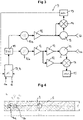
- the electronics 9 shown generate a first frequency-modulated electromagnetic wave with frequencies > 85 GHz (see e.g figure 5 with the signal form of the first wave in the frequency range over time t).
- the first wave generated by the signal generator 10a is amplified by amplifiers 12 and emitted by the first radar antenna 4a.
- the first wave thus emitted with a frequency between 99 and 102 GHz and a low bandwidth of 3 GHz is reflected from the upper edge of the layer 5 of the mold powder and fed from the radar antenna 4 to a rat-race coupler 16, which from the reflected first wave the emitted first wave separates.
- microcontroller 17 calculates in a known manner the height s P of the upper edge of layer 5 of the mold powder as a function of a delay between the first emitted wave and the first reflected wave, and on the other hand it receives the height s M of the upper edge of the mold level measuring device 7 via an input liquid metal in the mold 3. From the altitudes s P and s M the microcontroller 17 or the computing unit 8 calculates the thickness d of the layer of casting powder in the mold by taking the difference between s P and s M .
- the calculation of the layer thickness d can also be done by another system, such as a Level 1 PLC, which has access to s M and s P .
- the upper part of the in figure 3 Electronics 9 shown with the signal generator 10b is inactive when measuring the height s P of the upper edge of the layer of mold powder 5.
- Electronics 9 are in figure 1 arranged in a protected area away from the mold 3, so that the electronics are not exposed to high heat stress or the vibrations of the oscillating mold 3.
- the first wave 6 (see figure 5 ) is coupled by the electronics 9 into a waveguide protected by a steel tube 18 and is thus routed to the first radar antenna 4, 4a.
- the steel tube 18 protects the cable with the waveguide from heat, mechanical damage and steel spatter.
- the figure 2 shows a plan view of the mold 3 of the continuous casting plant figure 1 with the immersion tube 2 and the radar antenna 4 or 4a. From this it can be seen that the radar measurement for determining the height s P of the upper edge of the layer 5 of the mold powder is also suitable in the case of very cramped space conditions.
- the figure 4 shows a plan view of a mold 3 of a continuous slab casting plant with a centrally arranged immersion tube 2 and the radar antennas 4a and 4b.
- the height s M of the upper edge of the liquid metal in the mold 3 is also determined using radar technology. This functionality is in turn based on the electronics 9 in figure 3 explained.
- a signal generator 10b generates a second electromagnetic wave 6b with frequencies between 1 GHz and 4 GHz.
- the second wave is amplified by the amplifier 12 and conducted to the second radar antenna 4b by a circulator 13 and emitted by it. Since the second wave has very low frequencies compared to the first wave, it can pass through the cast powder layer and is reflected at the upper edge of the molten steel in mold 3 .
- the height s M of the upper edge of the molten steel is in turn determined in a manner known per se as a function of a delay between the second emitted wave and the second reflected wave.
- the input for s M of the electronics is 9 in figure 3 not used or not read out by the microcontroller 17.
- the figure 5 shows the signal form of a linearly polarized first frequency-modulated electromagnetic wave 6 in the frequency range as a function of time t.
- Wave 6 has the waveform of a sawtooth and performs a so-called frequency sweep between 99 and 102 GHz. After reaching the maximum frequency of 102 GHz, the frequency falls back to the minimum frequency of 99 GHz and the frequency again increases linearly as a function of time. It would also be conceivable to have a pause after the frequency has dropped not send a signal for a long time and then carry out another frequency sweep. This can be particularly useful when both the height s P of the upper edge of the layer of mold powder in the mold and the height s M of the upper edge of the liquid metal in the mold are measured by one and the same radar antenna.
- the figure 6 shows the signal forms of a linearly polarized first frequency-modulated electromagnetic wave 6a and a likewise linearly polarized second frequency-modulated electromagnetic wave 6b in the frequency range over time t.
- the first wave 6a is identical to the frequencies in the frequency sweep figure 5 .
- the signal pauses between two frequency sweeps, in which the second wave 6b is transmitted by the same radar antenna.
- the second wave 6b also carries out a frequency sweep, but between 1 and 4 GHz. After reaching the maximum frequency of 4 GHz, the signal pauses for a certain time, after which the frequency again increases linearly as a function of time.
- the first wave 6a can also be emitted at the same time as the second wave 6b. This is possible due to the separation of the frequency bands of the first wave 6a (frequencies between 99 and 102 GHz) and the second wave 6b (frequencies between 1 and 4 GHz). Accordingly, it is generally not necessary to send the first and second waves 6a, 6b sequentially or one after the other after a pause time. By sending out the first and second waves 6a, 6b at the same time, the sampling frequency for the thickness of the layer of mold powder can be increased without restricting the accuracy or reliability of the measuring system and measuring method.
Landscapes
- Physics & Mathematics (AREA)
- Engineering & Computer Science (AREA)
- Radar, Positioning & Navigation (AREA)
- Remote Sensing (AREA)
- General Physics & Mathematics (AREA)
- Electromagnetism (AREA)
- Fluid Mechanics (AREA)
- Mechanical Engineering (AREA)
- Thermal Sciences (AREA)
- Computer Networks & Wireless Communication (AREA)
- Measurement Of Levels Of Liquids Or Fluent Solid Materials (AREA)
- Continuous Casting (AREA)
- Length-Measuring Devices Using Wave Or Particle Radiation (AREA)
- Radar Systems Or Details Thereof (AREA)
Claims (15)
- Procédé destiné à la mesure d'une épaisseur d d'une couche d'une poudre de coulée (5) dans une lingotière (3) ; dans lequel la couche recouvre au moins en partie un métal en fusion dans la lingotière (3), le procédé comprenant les étapes opératoires dans lesquelles :on mesure une position en hauteur sP d'un bord supérieur de la couche, mesure au cours de laquelle une première onde électromagnétique modulée en fréquence (6, 6a) avec des fréquences > 85 GHz, de préférence < 135 GHz est générée, la première onde (6, 6a) est émise, le bord supérieur de la couche de la poudre de coulée (5) réfléchit la première onde (6, 6a), et la position en hauteur sp du bord supérieur de la couche est déterminée en fonction d'un retard entre la première onde (6, 6a) qui a été émise et la première onde qui a été réfléchie;on mesure une position en hauteur sM d'un bord supérieur du métal en fusion dans la lingotière (3); eton détermine l'épaisseur d de la couche de la poudre de coulée.
- Procédé selon la revendication 1, caractérisé en ce que, au cours de la mesure de la position en hauteur sM du bord supérieur du métal en fusion dans la lingotière (3), une deuxième onde électromagnétique modulée en fréquence (6b) avec des fréquences ≥ 1 GHz, de préférence < 13 GHz est générée, la deuxième onde (6b) est émise, le bord supérieur du métal en fusion réfléchit la deuxième onde (6b), et la position en hauteur sM du bord supérieur du métal en fusion est déterminée en fonction d'un retard entre la deuxième onde (6b) qui a été émise et la deuxième onde qui a été réfléchie.
- Procédé selon la revendication 1 ou 2, caractérisé en ce qu'un système électronique (9) est disposé dans une zone à l'écart de la lingotière (3), et une onde (6, 6a, 6b) qui a été émise est guidée à partir du système électronique (9) en direction d'une antenne radar (4, 4a, 4b) et vice versa et/ou une onde (6, 6a, 6b) qui a été émise est déviée à partir d'un miroir dans la direction de la poudre de coulée dans la lingotière (3) et vice versa.
- Procédé selon la revendication 1 ou 2, caractérisé en ce qu'un système électronique (9) est disposé au-dessus de la lingotière (3) ; dans lequel le système électronique (9) est de préférence refroidi par l'intermédiaire d'un milieu de refroidissement liquide ou gazeux.
- Procédé selon l'une quelconque des revendications 1 à 4, caractérisé en ce que la première onde (6, 6a) et/ou la deuxième onde (6b) qui a/ont été émise(s) est/sont guidée(s) dans un guide d'onde en direction de l'antenne radar (4, 4a, 4b) et/ou est/sont déviée(s) par l'intermédiaire d'un miroir dans la direction de la poudre de coulée dans la lingotière (3).
- Procédé selon la revendication 5, caractérisé en ce que la première (6, 6a) et la deuxième onde (6b) qui ont été émises, de même que la première onde et la deuxième onde qui ont été réfléchies sont guidées dans un guide d'onde unique et/ou sont déviées par l'intermédiaire d'un miroir unique.
- Procédé selon la revendication 1, caractérisé en ce que la mesure de la position en hauteur sM du métal en fusion dans la lingotière (3) a lieu par l'intermédiaire d'une mesure radiométrique ou d'une mesure électromagnétique.
- Dispositif destiné à la mesure d'une épaisseur d'une couche d'une poudre de coulée (5) dans une lingotière (3) à des fins de mise en œuvre du procédé selon l'une quelconque des revendications précédentes, qui comprend :un premier système électronique (9) qui est destiné à générer une première onde (6, 6a) qui a été émise avec une fréquence > 85 GHz, de préférence < 135 GHz, et à déterminer une position en hauteur sp d'un bord supérieur de la couche de la poudre de coulée dans la lingotière (3) en fonction d'un retard entre la première onde (6, 6a) qui a été émise et une première onde qui a été réfléchie;une première antenne radar (4, 4a) qui est destinée à émettre la première onde électromagnétique modulée en fréquence (6, 6a) et à recevoir la première onde électromagnétique qui a été réfléchie;un mécanisme (7) qui est destiné à la mesure d'une position en hauteur sM d'un bord supérieur du métal en fusion dans la lingotière (3); etune unité de calcul (8, 17) qui est destinée à déterminer l'épaisseur d de la couche de la poudre de coulée (5).
- Dispositif selon la revendication 8, caractérisé en ce que le mécanisme qui est destiné à la mesure de la position en hauteur sM du bord supérieur du métal en fusion dans la lingotière (3) comprend :une deuxième antenne radar (4b) qui est destinée à émettre une deuxième onde électromagnétique modulée en fréquence (6b) et à recevoir une deuxième onde électromagnétique qui a été réfléchie;un deuxième système électronique (9) qui est destiné à générer la deuxième onde (6b) qui a été réfléchie avec une fréquence ≥ 1 GHz, de préférence < 13 GHz et à déterminer une position en hauteur sM du bord supérieur du métal en fusion dans la lingotière (3) en fonction d'un retard entre la deuxième onde (6b) qui a été émise et la deuxième onde qui a été réfléchie.
- Dispositif selon la revendication 8 ou 9, caractérisé en ce que le premier et/ou le deuxième système électronique (9) est/sont disposé (s) dans une zone protégée à l'écart de la lingotière (3).
- Dispositif selon l'une quelconque des revendications 8 à 10, caractérisé en ce que le premier et/ou le deuxième système électronique (9) présente(nt) un mécanisme de refroidissement ; dans lequel le premier et/ou le deuxième système électronique (9) est/sont refroidi(s) par l'intermédiaire d'un milieu de refroidissement liquide ou gazeux.
- Dispositif selon la revendication 10, caractérisé en ce que, entre un système électronique (9) et une antenne radar (4, 4a, 4b), est disposé un guide d'onde qui est destiné au guidage d'une onde électromagnétique et/ou un miroir à des fins de déviation d'une onde électromagnétique.
- Dispositif selon l'une quelconque des revendications 8 à 12, caractérisé en ce qu'un câble qui guide la première et/ou la deuxième onde (6, 6a, 6b) est protégé par l'intermédiaire d'un tube, de préférence par l'intermédiaire d'un tube en acier (18) .
- Dispositif selon l'une quelconque des revendications 8 à 13, caractérisé en ce que la lingotière (3) présente plusieurs antennes radars (4, 4a, 4b) et/ou une antenne radar (4, 4a, 4b) est réalisée de manière à pouvoir être déplacée.
- Dispositif selon la revendication 8, caractérisé en ce que le mécanisme (7) qui est destiné à la mesure d'une position en hauteur sM d'un bord supérieur du métal en fusion dans la lingotière (3) est réalisé sous la forme d'un mécanisme de mesure (7) de type radiométrique ou électromagnétique.
Applications Claiming Priority (2)
| Application Number | Priority Date | Filing Date | Title |
|---|---|---|---|
| ATA51020/2018A AT521924B1 (de) | 2018-11-21 | 2018-11-21 | Dickenmessung einer Schicht eines Gieß- oder Abdeckpulvers in einer Kokille |
| PCT/EP2019/080691 WO2020104217A1 (fr) | 2018-11-21 | 2019-11-08 | Mesure de l'épaisseur d'une couche d'une poudre de coulée dans une lingotière |
Publications (2)
| Publication Number | Publication Date |
|---|---|
| EP3883706A1 EP3883706A1 (fr) | 2021-09-29 |
| EP3883706B1 true EP3883706B1 (fr) | 2022-04-20 |
Family
ID=68610169
Family Applications (1)
| Application Number | Title | Priority Date | Filing Date |
|---|---|---|---|
| EP19805560.0A Active EP3883706B1 (fr) | 2018-11-21 | 2019-11-08 | Mesure de l'épaisseur d'une couche d'une poudre de coulée dans une lingotière |
Country Status (3)
| Country | Link |
|---|---|
| EP (1) | EP3883706B1 (fr) |
| AT (1) | AT521924B1 (fr) |
| WO (1) | WO2020104217A1 (fr) |
Families Citing this family (1)
| Publication number | Priority date | Publication date | Assignee | Title |
|---|---|---|---|---|
| CN113000802B (zh) * | 2021-02-22 | 2023-04-21 | 内蒙古科技大学 | 一种连铸结晶器内保护渣厚度测量装置及方法 |
Family Cites Families (11)
| Publication number | Priority date | Publication date | Assignee | Title |
|---|---|---|---|---|
| SE501472C2 (sv) * | 1993-02-03 | 1995-02-27 | Stiftelsen Metallurg Forsk | Sätt att vid metallurgiska processer mäta positionerna av ytor mellan olika skikt |
| SE9501866L (sv) | 1995-05-19 | 1996-11-20 | Stiftelsen Metallurg Forsk | Sätt att stränggjuta metall |
| US6166681A (en) * | 1998-08-18 | 2000-12-26 | Usx Corporation | Measuring the thickness of materials |
| US6987481B2 (en) * | 2003-04-25 | 2006-01-17 | Vega Grieshaber Kg | Radar filling level measurement using circularly polarized waves |
| JP4765517B2 (ja) | 2005-09-27 | 2011-09-07 | Jfeスチール株式会社 | 連続鋳造用モールドパウダー自動供給装置 |
| EP2090387A1 (fr) * | 2008-01-18 | 2009-08-19 | Corus Staal BV | Procédé et appareil pour surveiller les surfaces de laitier et métal fondu dans un moule |
| DE102010015670A1 (de) | 2010-04-21 | 2011-10-27 | Sms Siemag Ag | Anordnung und Verfahren zur Steuerung einer Gießpulveraufgabe einer Stranggießanlage |
| JP5690230B2 (ja) | 2011-06-27 | 2015-03-25 | 新日鐵住金株式会社 | 連続鋳造用モールドパウダーの溶融層厚み測定方法 |
| JP5800241B2 (ja) | 2012-08-08 | 2015-10-28 | 新日鐵住金株式会社 | 連続鋳造用鋳型内の溶融金属の湯面レベル及びモールドパウダー厚の測定方法 |
| KR20170014002A (ko) * | 2014-07-30 | 2017-02-07 | 신닛테츠스미킨 카부시키카이샤 | 용융 금속의 탕면 상에 부유하는 슬래그의 두께 측정 방법 |
| AT517130A1 (de) | 2015-04-29 | 2016-11-15 | Primetals Technologies Austria GmbH | Schlackedetektion in einem Verteiler einer Stranggießanlage |
-
2018
- 2018-11-21 AT ATA51020/2018A patent/AT521924B1/de active
-
2019
- 2019-11-08 EP EP19805560.0A patent/EP3883706B1/fr active Active
- 2019-11-08 WO PCT/EP2019/080691 patent/WO2020104217A1/fr not_active Ceased
Also Published As
| Publication number | Publication date |
|---|---|
| AT521924B1 (de) | 2021-03-15 |
| AT521924A1 (de) | 2020-06-15 |
| EP3883706A1 (fr) | 2021-09-29 |
| WO2020104217A1 (fr) | 2020-05-28 |
Similar Documents
| Publication | Publication Date | Title |
|---|---|---|
| EP2128576B1 (fr) | Procédé de détection de double parole basé sur les propriétés acoustiques spectrales | |
| DE60034631T2 (de) | Erkennung der schnittstelle zwischen mehreren prozess-produkten für ein füllstandmess-radargerät mit niedriger leistung | |
| EP0198910A1 (fr) | Procede et dispositif de detection des scories. | |
| EP2861944B1 (fr) | Jauge de niveau et dispositif pour déterminer la constante diélectrique | |
| AT390680B (de) | Sonde zum leiten mechanischer ultraschallenergie | |
| EP1069438A1 (fr) | Procédé et dispositif pour la détermination du niveau de remplissage d'un produit dans un réservoir avec haute précision | |
| CN102036771A (zh) | 用于监测模具中的熔渣和熔融金属的表面的方法和设备 | |
| DE2107586A1 (de) | Ultraschall Durchflußmesser | |
| DE102011007372A1 (de) | Kalibrations- und/oder Überwachungsverfahren für FMCW-Radar Füllstandsmessgeräte | |
| WO2002010696A1 (fr) | Dispositif de mesure du niveau d'un materiau de remplissage dans un contenant | |
| EP1813940A2 (fr) | Dispositif pour déterminer la caractéristique d'un métal en fusion ou d'une couche de scories se trouvant sur le métal en fusion | |
| EP3883706B1 (fr) | Mesure de l'épaisseur d'une couche d'une poudre de coulée dans une lingotière | |
| DE2600154C2 (de) | Verfahren und Einrichtung zum Messen der Dicke flächigen Guts mittels Schallwellen | |
| DE102014112453A1 (de) | Radarfüllstandmessgerät | |
| DE102009059780A1 (de) | Einwurfsonde | |
| EP1955026B1 (fr) | Generation d'impulsions de reference | |
| EP0172394A1 (fr) | Procédé et appareil pour le contrôle du laitier dans un panier lors de la coulée continue de métal, en particulier d'acier | |
| DE69211532T2 (de) | Testsystem mit wechselfeldmessung | |
| EP1004858A1 (fr) | Jauge de niveau de remplissage | |
| WO2021104839A1 (fr) | Dispositif de mesure de distance basé sur une fmcw | |
| EP1965182A2 (fr) | Appareil de mesure du niveau de remplissage | |
| EP0158628A2 (fr) | Procédé pour couler du métal fondu ainsi que dispositif pour la mise en oeuvre de ce procédé | |
| EP0971213B1 (fr) | Appareil à micro-ondes de mesure de niveau de contenu avec qualité de signal améliorée | |
| DE3307393C2 (fr) | ||
| WO2001096900A1 (fr) | Procede et dispositif d'amelioration de la stabilite a la temperature et de la resistance au vieillissement de mesureurs de niveau a radar a l'aide d'une reference mecanique |
Legal Events
| Date | Code | Title | Description |
|---|---|---|---|
| STAA | Information on the status of an ep patent application or granted ep patent |
Free format text: STATUS: UNKNOWN |
|
| STAA | Information on the status of an ep patent application or granted ep patent |
Free format text: STATUS: THE INTERNATIONAL PUBLICATION HAS BEEN MADE |
|
| PUAI | Public reference made under article 153(3) epc to a published international application that has entered the european phase |
Free format text: ORIGINAL CODE: 0009012 |
|
| STAA | Information on the status of an ep patent application or granted ep patent |
Free format text: STATUS: REQUEST FOR EXAMINATION WAS MADE |
|
| 17P | Request for examination filed |
Effective date: 20210504 |
|
| AK | Designated contracting states |
Kind code of ref document: A1 Designated state(s): AL AT BE BG CH CY CZ DE DK EE ES FI FR GB GR HR HU IE IS IT LI LT LU LV MC MK MT NL NO PL PT RO RS SE SI SK SM TR |
|
| TPAC | Observations filed by third parties |
Free format text: ORIGINAL CODE: EPIDOSNTIPA |
|
| GRAP | Despatch of communication of intention to grant a patent |
Free format text: ORIGINAL CODE: EPIDOSNIGR1 |
|
| STAA | Information on the status of an ep patent application or granted ep patent |
Free format text: STATUS: GRANT OF PATENT IS INTENDED |
|
| INTG | Intention to grant announced |
Effective date: 20211215 |
|
| DAV | Request for validation of the european patent (deleted) | ||
| DAX | Request for extension of the european patent (deleted) | ||
| GRAS | Grant fee paid |
Free format text: ORIGINAL CODE: EPIDOSNIGR3 |
|
| GRAA | (expected) grant |
Free format text: ORIGINAL CODE: 0009210 |
|
| STAA | Information on the status of an ep patent application or granted ep patent |
Free format text: STATUS: THE PATENT HAS BEEN GRANTED |
|
| AK | Designated contracting states |
Kind code of ref document: B1 Designated state(s): AL AT BE BG CH CY CZ DE DK EE ES FI FR GB GR HR HU IE IS IT LI LT LU LV MC MK MT NL NO PL PT RO RS SE SI SK SM TR |
|
| REG | Reference to a national code |
Ref country code: GB Ref legal event code: FG4D Free format text: NOT ENGLISH |
|
| REG | Reference to a national code |
Ref country code: CH Ref legal event code: EP |
|
| REG | Reference to a national code |
Ref country code: DE Ref legal event code: R096 Ref document number: 502019004151 Country of ref document: DE |
|
| REG | Reference to a national code |
Ref country code: IE Ref legal event code: FG4D Free format text: LANGUAGE OF EP DOCUMENT: GERMAN |
|
| REG | Reference to a national code |
Ref country code: AT Ref legal event code: REF Ref document number: 1484771 Country of ref document: AT Kind code of ref document: T Effective date: 20220515 |
|
| REG | Reference to a national code |
Ref country code: LT Ref legal event code: MG9D |
|
| REG | Reference to a national code |
Ref country code: NL Ref legal event code: MP Effective date: 20220420 |
|
| PG25 | Lapsed in a contracting state [announced via postgrant information from national office to epo] |
Ref country code: NL Free format text: LAPSE BECAUSE OF FAILURE TO SUBMIT A TRANSLATION OF THE DESCRIPTION OR TO PAY THE FEE WITHIN THE PRESCRIBED TIME-LIMIT Effective date: 20220420 |
|
| PG25 | Lapsed in a contracting state [announced via postgrant information from national office to epo] |
Ref country code: SE Free format text: LAPSE BECAUSE OF FAILURE TO SUBMIT A TRANSLATION OF THE DESCRIPTION OR TO PAY THE FEE WITHIN THE PRESCRIBED TIME-LIMIT Effective date: 20220420 Ref country code: PT Free format text: LAPSE BECAUSE OF FAILURE TO SUBMIT A TRANSLATION OF THE DESCRIPTION OR TO PAY THE FEE WITHIN THE PRESCRIBED TIME-LIMIT Effective date: 20220822 Ref country code: NO Free format text: LAPSE BECAUSE OF FAILURE TO SUBMIT A TRANSLATION OF THE DESCRIPTION OR TO PAY THE FEE WITHIN THE PRESCRIBED TIME-LIMIT Effective date: 20220720 Ref country code: LT Free format text: LAPSE BECAUSE OF FAILURE TO SUBMIT A TRANSLATION OF THE DESCRIPTION OR TO PAY THE FEE WITHIN THE PRESCRIBED TIME-LIMIT Effective date: 20220420 Ref country code: HR Free format text: LAPSE BECAUSE OF FAILURE TO SUBMIT A TRANSLATION OF THE DESCRIPTION OR TO PAY THE FEE WITHIN THE PRESCRIBED TIME-LIMIT Effective date: 20220420 Ref country code: GR Free format text: LAPSE BECAUSE OF FAILURE TO SUBMIT A TRANSLATION OF THE DESCRIPTION OR TO PAY THE FEE WITHIN THE PRESCRIBED TIME-LIMIT Effective date: 20220721 Ref country code: FI Free format text: LAPSE BECAUSE OF FAILURE TO SUBMIT A TRANSLATION OF THE DESCRIPTION OR TO PAY THE FEE WITHIN THE PRESCRIBED TIME-LIMIT Effective date: 20220420 Ref country code: ES Free format text: LAPSE BECAUSE OF FAILURE TO SUBMIT A TRANSLATION OF THE DESCRIPTION OR TO PAY THE FEE WITHIN THE PRESCRIBED TIME-LIMIT Effective date: 20220420 Ref country code: BG Free format text: LAPSE BECAUSE OF FAILURE TO SUBMIT A TRANSLATION OF THE DESCRIPTION OR TO PAY THE FEE WITHIN THE PRESCRIBED TIME-LIMIT Effective date: 20220720 |
|
| PG25 | Lapsed in a contracting state [announced via postgrant information from national office to epo] |
Ref country code: RS Free format text: LAPSE BECAUSE OF FAILURE TO SUBMIT A TRANSLATION OF THE DESCRIPTION OR TO PAY THE FEE WITHIN THE PRESCRIBED TIME-LIMIT Effective date: 20220420 Ref country code: PL Free format text: LAPSE BECAUSE OF FAILURE TO SUBMIT A TRANSLATION OF THE DESCRIPTION OR TO PAY THE FEE WITHIN THE PRESCRIBED TIME-LIMIT Effective date: 20220420 Ref country code: LV Free format text: LAPSE BECAUSE OF FAILURE TO SUBMIT A TRANSLATION OF THE DESCRIPTION OR TO PAY THE FEE WITHIN THE PRESCRIBED TIME-LIMIT Effective date: 20220420 Ref country code: IS Free format text: LAPSE BECAUSE OF FAILURE TO SUBMIT A TRANSLATION OF THE DESCRIPTION OR TO PAY THE FEE WITHIN THE PRESCRIBED TIME-LIMIT Effective date: 20220820 |
|
| REG | Reference to a national code |
Ref country code: DE Ref legal event code: R097 Ref document number: 502019004151 Country of ref document: DE |
|
| PG25 | Lapsed in a contracting state [announced via postgrant information from national office to epo] |
Ref country code: SM Free format text: LAPSE BECAUSE OF FAILURE TO SUBMIT A TRANSLATION OF THE DESCRIPTION OR TO PAY THE FEE WITHIN THE PRESCRIBED TIME-LIMIT Effective date: 20220420 Ref country code: SK Free format text: LAPSE BECAUSE OF FAILURE TO SUBMIT A TRANSLATION OF THE DESCRIPTION OR TO PAY THE FEE WITHIN THE PRESCRIBED TIME-LIMIT Effective date: 20220420 Ref country code: RO Free format text: LAPSE BECAUSE OF FAILURE TO SUBMIT A TRANSLATION OF THE DESCRIPTION OR TO PAY THE FEE WITHIN THE PRESCRIBED TIME-LIMIT Effective date: 20220420 Ref country code: EE Free format text: LAPSE BECAUSE OF FAILURE TO SUBMIT A TRANSLATION OF THE DESCRIPTION OR TO PAY THE FEE WITHIN THE PRESCRIBED TIME-LIMIT Effective date: 20220420 Ref country code: DK Free format text: LAPSE BECAUSE OF FAILURE TO SUBMIT A TRANSLATION OF THE DESCRIPTION OR TO PAY THE FEE WITHIN THE PRESCRIBED TIME-LIMIT Effective date: 20220420 Ref country code: CZ Free format text: LAPSE BECAUSE OF FAILURE TO SUBMIT A TRANSLATION OF THE DESCRIPTION OR TO PAY THE FEE WITHIN THE PRESCRIBED TIME-LIMIT Effective date: 20220420 |
|
| PLBE | No opposition filed within time limit |
Free format text: ORIGINAL CODE: 0009261 |
|
| STAA | Information on the status of an ep patent application or granted ep patent |
Free format text: STATUS: NO OPPOSITION FILED WITHIN TIME LIMIT |
|
| 26N | No opposition filed |
Effective date: 20230123 |
|
| PG25 | Lapsed in a contracting state [announced via postgrant information from national office to epo] |
Ref country code: AL Free format text: LAPSE BECAUSE OF FAILURE TO SUBMIT A TRANSLATION OF THE DESCRIPTION OR TO PAY THE FEE WITHIN THE PRESCRIBED TIME-LIMIT Effective date: 20220420 |
|
| PG25 | Lapsed in a contracting state [announced via postgrant information from national office to epo] |
Ref country code: MC Free format text: LAPSE BECAUSE OF FAILURE TO SUBMIT A TRANSLATION OF THE DESCRIPTION OR TO PAY THE FEE WITHIN THE PRESCRIBED TIME-LIMIT Effective date: 20220420 |
|
| REG | Reference to a national code |
Ref country code: BE Ref legal event code: MM Effective date: 20221130 |
|
| PG25 | Lapsed in a contracting state [announced via postgrant information from national office to epo] |
Ref country code: LU Free format text: LAPSE BECAUSE OF NON-PAYMENT OF DUE FEES Effective date: 20221108 |
|
| PG25 | Lapsed in a contracting state [announced via postgrant information from national office to epo] |
Ref country code: IE Free format text: LAPSE BECAUSE OF NON-PAYMENT OF DUE FEES Effective date: 20221108 |
|
| PG25 | Lapsed in a contracting state [announced via postgrant information from national office to epo] |
Ref country code: FR Free format text: LAPSE BECAUSE OF NON-PAYMENT OF DUE FEES Effective date: 20221130 Ref country code: BE Free format text: LAPSE BECAUSE OF NON-PAYMENT OF DUE FEES Effective date: 20221130 |
|
| PG25 | Lapsed in a contracting state [announced via postgrant information from national office to epo] |
Ref country code: CY Free format text: LAPSE BECAUSE OF FAILURE TO SUBMIT A TRANSLATION OF THE DESCRIPTION OR TO PAY THE FEE WITHIN THE PRESCRIBED TIME-LIMIT Effective date: 20220420 |
|
| PG25 | Lapsed in a contracting state [announced via postgrant information from national office to epo] |
Ref country code: MK Free format text: LAPSE BECAUSE OF FAILURE TO SUBMIT A TRANSLATION OF THE DESCRIPTION OR TO PAY THE FEE WITHIN THE PRESCRIBED TIME-LIMIT Effective date: 20220420 Ref country code: HU Free format text: LAPSE BECAUSE OF FAILURE TO SUBMIT A TRANSLATION OF THE DESCRIPTION OR TO PAY THE FEE WITHIN THE PRESCRIBED TIME-LIMIT; INVALID AB INITIO Effective date: 20191108 |
|
| PG25 | Lapsed in a contracting state [announced via postgrant information from national office to epo] |
Ref country code: TR Free format text: LAPSE BECAUSE OF FAILURE TO SUBMIT A TRANSLATION OF THE DESCRIPTION OR TO PAY THE FEE WITHIN THE PRESCRIBED TIME-LIMIT Effective date: 20220420 |
|
| GBPC | Gb: european patent ceased through non-payment of renewal fee |
Effective date: 20231108 |
|
| PG25 | Lapsed in a contracting state [announced via postgrant information from national office to epo] |
Ref country code: MT Free format text: LAPSE BECAUSE OF FAILURE TO SUBMIT A TRANSLATION OF THE DESCRIPTION OR TO PAY THE FEE WITHIN THE PRESCRIBED TIME-LIMIT Effective date: 20220420 |
|
| PG25 | Lapsed in a contracting state [announced via postgrant information from national office to epo] |
Ref country code: GB Free format text: LAPSE BECAUSE OF NON-PAYMENT OF DUE FEES Effective date: 20231108 |
|
| PG25 | Lapsed in a contracting state [announced via postgrant information from national office to epo] |
Ref country code: GB Free format text: LAPSE BECAUSE OF NON-PAYMENT OF DUE FEES Effective date: 20231108 |
|
| PG25 | Lapsed in a contracting state [announced via postgrant information from national office to epo] |
Ref country code: BG Free format text: LAPSE BECAUSE OF FAILURE TO SUBMIT A TRANSLATION OF THE DESCRIPTION OR TO PAY THE FEE WITHIN THE PRESCRIBED TIME-LIMIT Effective date: 20220420 |
|
| PG25 | Lapsed in a contracting state [announced via postgrant information from national office to epo] |
Ref country code: BG Free format text: LAPSE BECAUSE OF FAILURE TO SUBMIT A TRANSLATION OF THE DESCRIPTION OR TO PAY THE FEE WITHIN THE PRESCRIBED TIME-LIMIT Effective date: 20220420 |
|
| REG | Reference to a national code |
Ref country code: CH Ref legal event code: U11 Free format text: ST27 STATUS EVENT CODE: U-0-0-U10-U11 (AS PROVIDED BY THE NATIONAL OFFICE) Effective date: 20251201 |
|
| PGFP | Annual fee paid to national office [announced via postgrant information from national office to epo] |
Ref country code: DE Payment date: 20251119 Year of fee payment: 7 |
|
| PG25 | Lapsed in a contracting state [announced via postgrant information from national office to epo] |
Ref country code: AT Free format text: LAPSE BECAUSE OF NON-PAYMENT OF DUE FEES Effective date: 20241108 |
|
| PGFP | Annual fee paid to national office [announced via postgrant information from national office to epo] |
Ref country code: IT Payment date: 20251125 Year of fee payment: 7 |
|
| REG | Reference to a national code |
Ref country code: AT Ref legal event code: MM01 Ref document number: 1484771 Country of ref document: AT Kind code of ref document: T Effective date: 20241108 |
|
| PGFP | Annual fee paid to national office [announced via postgrant information from national office to epo] |
Ref country code: CH Payment date: 20251201 Year of fee payment: 7 |
|
| PG25 | Lapsed in a contracting state [announced via postgrant information from national office to epo] |
Ref country code: SI Free format text: LAPSE BECAUSE OF FAILURE TO SUBMIT A TRANSLATION OF THE DESCRIPTION OR TO PAY THE FEE WITHIN THE PRESCRIBED TIME-LIMIT Effective date: 20220420 |
|
| PGFP | Annual fee paid to national office [announced via postgrant information from national office to epo] |
Ref country code: AT Payment date: 20260410 Year of fee payment: 5 |