EP3884239B1 - Capteur d'angle avec aimant multipole pour la direction d'un véhicule automobile - Google Patents
Capteur d'angle avec aimant multipole pour la direction d'un véhicule automobile Download PDFInfo
- Publication number
- EP3884239B1 EP3884239B1 EP19813430.6A EP19813430A EP3884239B1 EP 3884239 B1 EP3884239 B1 EP 3884239B1 EP 19813430 A EP19813430 A EP 19813430A EP 3884239 B1 EP3884239 B1 EP 3884239B1
- Authority
- EP
- European Patent Office
- Prior art keywords
- magnetic field
- magnetic
- angle
- multipole
- sensors
- Prior art date
- Legal status (The legal status is an assumption and is not a legal conclusion. Google has not performed a legal analysis and makes no representation as to the accuracy of the status listed.)
- Active
Links
Images


Classifications
-
- B—PERFORMING OPERATIONS; TRANSPORTING
- B62—LAND VEHICLES FOR TRAVELLING OTHERWISE THAN ON RAILS
- B62D—MOTOR VEHICLES; TRAILERS
- B62D15/00—Steering not otherwise provided for
- B62D15/02—Steering position indicators ; Steering position determination; Steering aids
- B62D15/021—Determination of steering angle
- B62D15/0215—Determination of steering angle by measuring on the steering column
-
- G—PHYSICS
- G01—MEASURING; TESTING
- G01D—MEASURING NOT SPECIALLY ADAPTED FOR A SPECIFIC VARIABLE; ARRANGEMENTS FOR MEASURING TWO OR MORE VARIABLES NOT COVERED IN A SINGLE OTHER SUBCLASS; TARIFF METERING APPARATUS; MEASURING OR TESTING NOT OTHERWISE PROVIDED FOR
- G01D5/00—Mechanical means for transferring the output of a sensing member; Means for converting the output of a sensing member to another variable where the form or nature of the sensing member does not constrain the means for converting; Transducers not specially adapted for a specific variable
- G01D5/12—Mechanical means for transferring the output of a sensing member; Means for converting the output of a sensing member to another variable where the form or nature of the sensing member does not constrain the means for converting; Transducers not specially adapted for a specific variable using electric or magnetic means
- G01D5/14—Mechanical means for transferring the output of a sensing member; Means for converting the output of a sensing member to another variable where the form or nature of the sensing member does not constrain the means for converting; Transducers not specially adapted for a specific variable using electric or magnetic means influencing the magnitude of a current or voltage
- G01D5/142—Mechanical means for transferring the output of a sensing member; Means for converting the output of a sensing member to another variable where the form or nature of the sensing member does not constrain the means for converting; Transducers not specially adapted for a specific variable using electric or magnetic means influencing the magnitude of a current or voltage using Hall-effect devices
- G01D5/145—Mechanical means for transferring the output of a sensing member; Means for converting the output of a sensing member to another variable where the form or nature of the sensing member does not constrain the means for converting; Transducers not specially adapted for a specific variable using electric or magnetic means influencing the magnitude of a current or voltage using Hall-effect devices influenced by the relative movement between the Hall device and magnetic fields
-
- G—PHYSICS
- G01—MEASURING; TESTING
- G01B—MEASURING LENGTH, THICKNESS OR SIMILAR LINEAR DIMENSIONS; MEASURING ANGLES; MEASURING AREAS; MEASURING IRREGULARITIES OF SURFACES OR CONTOURS
- G01B7/00—Measuring arrangements characterised by the use of electric or magnetic techniques
- G01B7/30—Measuring arrangements characterised by the use of electric or magnetic techniques for measuring angles or tapers; for testing the alignment of axes
-
- G—PHYSICS
- G01—MEASURING; TESTING
- G01D—MEASURING NOT SPECIALLY ADAPTED FOR A SPECIFIC VARIABLE; ARRANGEMENTS FOR MEASURING TWO OR MORE VARIABLES NOT COVERED IN A SINGLE OTHER SUBCLASS; TARIFF METERING APPARATUS; MEASURING OR TESTING NOT OTHERWISE PROVIDED FOR
- G01D5/00—Mechanical means for transferring the output of a sensing member; Means for converting the output of a sensing member to another variable where the form or nature of the sensing member does not constrain the means for converting; Transducers not specially adapted for a specific variable
- G01D5/12—Mechanical means for transferring the output of a sensing member; Means for converting the output of a sensing member to another variable where the form or nature of the sensing member does not constrain the means for converting; Transducers not specially adapted for a specific variable using electric or magnetic means
- G01D5/244—Mechanical means for transferring the output of a sensing member; Means for converting the output of a sensing member to another variable where the form or nature of the sensing member does not constrain the means for converting; Transducers not specially adapted for a specific variable using electric or magnetic means influencing characteristics of pulses or pulse trains; generating pulses or pulse trains
- G01D5/24471—Error correction
- G01D5/24485—Error correction using other sensors
-
- G—PHYSICS
- G01—MEASURING; TESTING
- G01R—MEASURING ELECTRIC VARIABLES; MEASURING MAGNETIC VARIABLES
- G01R33/00—Arrangements or instruments for measuring magnetic variables
- G01R33/02—Measuring direction or magnitude of magnetic fields or magnetic flux
- G01R33/06—Measuring direction or magnitude of magnetic fields or magnetic flux using galvano-magnetic devices
- G01R33/07—Hall effect devices
- G01R33/072—Constructional adaptation of the sensor to specific applications
Definitions
- the present invention relates to an angle sensor with the features of claim 1, an electromechanical power steering system and a steer-by-wire steering system for a motor vehicle having the corresponding angle sensors and a method for determining an angle of rotation of the rotational position of a rotatably mounted steering shaft of a motor vehicle with the features of claim 9.
- Angle sensors are used in a motor vehicle, among other things, to measure the steering angle of the steering wheel.
- Angle sensors currently in use are magnetic sensors whose measurements can be easily disturbed by external magnetic fields.
- motor vehicles will be fully or partially electrically operated, which can lead to high external field interference measurements from high-current cables, which are often located near the steering system. These disturbances to the magnetic sensors can therefore negatively affect the steering feel and robustness of the steering.
- EP 2 552 000 A2 discloses an electric motor with a rotor position sensor, which detects a stray magnetic field of the permanent magnet rotor and generates the rotor position signal depending on the stray magnetic field.
- the electric motor therefore advantageously does not need a separate rotor position magnet to detect the rotor position of the rotor. It is also clear from the publication EN 10 2008 043 265 A1 known to be caused by a To compensate for disturbances caused by a magnetic interference field, by determining the magnetic interference field and subtracting it vectorially from a magnetic field vector.
- the EP 1 777 501 A1 a position sensor for contactless position determination is known, which provides for the use of a multipole magnet ring with at least two magnetically sensitive sensor elements offset from each other for interference field compensation.
- the position sensor is also suitable for angle determination.
- a similarly designed sensor for determining an angle is known from US 5 568 048 A
- Another angle sensor with several sensors assigned to a magnet is known from the US 2012/161755 A1
- Other similar sensor systems, which provide two multipole magnet rings, with each of the magnet rings being assigned a magnetically sensitive sensor are known from EN 10 2015 114 608 A1 and from the EP 1 818 659 A1 known.
- US 2003/145663 A1 A sensor system with multipole magnetic rings and several sensor elements is described. For use in encoders and tachometers, the use of magnetic rings with a large number of poles and a sensor arrangement assigned to them is US 5 680 042 A known.
- an angle sensor unit for measuring a rotation angle of the rotational position of a steering shaft of a motor vehicle has a multipole magnet ring with a number of pole pairs, which can be connected to the steering shaft in a rotationally fixed manner, at least two magnetic field sensors which are assigned to the multipole magnet ring and an evaluation unit which is set up to use the signals of the at least two magnetic field sensors to determine a
- the at least two magnetic field sensors are arranged on the outside of the multipole magnet ring, offset in the circumferential direction, such that a magnetic field emanating from the multipole magnet ring has an approximately equal absolute value but opposite signs in the area of both magnetic field sensors. This arrangement makes it possible to eliminate stray field interference by differential measurements of the two magnetic field sensors and thus to determine an interference-free angle of rotation.
- the sensitive sensor surfaces of the two sensors are preferably located in a plane that extends tangentially to the outer surface of the multipole magnet ring, in the middle between the two sensors.
- the vectorial magnetic flux of the magnetic field generated by the multipole magnet ring forms the same angle with the plane of the sensor surface, i.e.
- An external magnetic interference field is preferably homogeneous in the area of the two sensors.
- the magnetic field sensors have a distance in the circumferential direction that is less than 45°, in particular less than 20°.
- the magnetic field sensors are arranged offset by one pole in the circumferential direction. This ensures that the interference field in the area of both sensors is homogeneous and can be calculated out using a differential measurement.
- the sensitive sensor surfaces of the magnetic field sensors lie in one plane and have a distance in a range between 40% and 90% of the diameter of the multipole magnet ring.
- the multipole magnet ring preferably has at least four pole pairs.
- the evaluation unit is preferably designed to determine an angle of rotation independently of an external magnetic interference field by subtracting the signals from the two magnetic field sensors.
- the invention provides a two-pole magnetic ring with associated magnetic field sensor to add to the arrangement.
- the poles of the multipole magnet ring are preferably formed by permanent magnets and/or the magnetic field sensors are Hall sensors or xMR sensors.
- the distance between the two magnetic field sensors and the magnetic field formed in the area of the sensors are thus designed in such a way that an interference-free angle of rotation can be measured via a differential measurement.
- the two multipole magnet rings are preferably identical and are arranged one behind the other in the axial direction, preferably in contact with one another.
- the multipole magnet rings each have an axial pole width and the distance between the magnetic field sensors is less than 110% of the axial pole width, and in particular greater than 90%.
- the distance between the magnetic field sensors is between 40% and 60% of the total extension of the two multipole magnet rings in axial direction.
- an electromechanical power steering system for a motor vehicle comprising a steering shaft which is mounted rotatably about a steering shaft rotation axis and can assume different rotational positions, an electric motor for Support of a steering movement and a previously mentioned angle sensor unit are provided.
- the aforementioned angle sensor unit can also be used in a steer-by-wire steering system for motor vehicles comprising a steering actuator acting on the steered wheels and electronically controlled depending on a driver's steering request, a feedback actuator transmitting road reactions to a steering wheel, and a control unit which controls the feedback actuator and the steering actuator.
- CORDIC Coordinate Rotation Digital Computer
- a weighting is carried out when forming the difference.
- the magnetic field sensors are arranged offset by one pole in the circumferential direction. Further preferred embodiments can be taken from the device described above.
- the multipole magnet rings each have an axial pole width and the axial distance between the magnetic field sensors is less than 110%, and in particular greater than 90%, of the axial pole width.
- the axial distance between the magnetic field sensors is between 40% and 60% of the total extension of the two multipole magnet rings in the axial direction. Further preferred embodiments can be taken from the device described above.
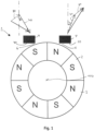
- a steering angle sensor unit 1 is shown schematically.
- a multipole magnet ring 2 concentrically surrounds a shaft (not shown) and is connected to this shaft in a rotationally fixed manner.
- the multipole magnet ring 2 has has a plurality of permanent magnets along its circumference.
- the arrangement of the magnets 3 is selected such that a north and a south pole are located alternately along the outer edge of the multipole magnet ring 2.
- a rotation of the multipole magnet ring 2 or the shaft leads to a magnetic field that changes over time, which is detected by two sensors 4, 5.
- the two sensors 4, 5 are preferably Hall sensors. They are arranged in a fixed space.
- the sensors 4, 5 are located on the outside of the multipole magnet ring 2 and are arranged radially spaced from it in relation to a longitudinal axis 100, across a small air gap 6 for measuring the magnetic field emanating from the multipole magnet ring 2.
- the two sensors 4, 5 are arranged in the circumferential direction around the longitudinal axis 100 at a distance of one pole. In other words, a first sensor 4 faces a south pole and a second sensor 5 faces a north pole immediately adjacent to the south pole.
- the sensors 4,5 therefore have a distance in the circumferential direction of 360°/(2*X) for X pole pairs.
- the signals from the two sensors 4,5 are evaluated in an evaluation unit.
- the evaluation unit is equipped with an incremental counter so that the periods of a generated periodic fluctuation in the magnetic field strength can be counted when the multipole magnet wheel 2 rotates more.
- the sensors are so close to each other in the circumferential direction that it can be assumed that an external magnetic interference field is homogeneous in the area of both sensors.
- the sensitive sensor surfaces of the two sensors 40,50 lie in a plane that extends tangentially to the outer surface of the multipole magnet ring 2, in the middle between the two sensors 4,5.
- the vectorial magnetic flux of the magnetic field generated by the multipole magnet ring 2 forms the same angle with the plane of the sensor surface 40,50, ie
- FIG. 1 is the magnetic field generated by the multipole magnet ring in the plane of the two sensor surfaces 40,50 Magnetic field shown as a dashed vector 70,71, where ⁇ is the angle that the vector 71 makes with the plumb line on the sensor surface 50 and ⁇ is the angle that the vector 70 makes with the plumb line on the sensor surface 40.
- An external interference field 80,81 (dotted vectors) and the resulting magnetic field 90,91 measured by the sensors (solid line) are also shown as a vector. As already explained, it can be assumed that the interference field 80,81 is the same for both sensors.
- the signals of the two sensors 4,5 are split into tangential components 41,51 and radial components 41,51, as shown in the block diagram for determining the angle of rotation of the Figure 2 is shown.
- the radial and tangential signal components of the two sensors 41,51,41,51 are weighted and subtracted from each other 61,72 in order to obtain an interference-free signal. It can be provided that a delay and an offset in the signals are set independently of each other. If xMR technology is used as a sensor, it is possible to create complete vectors with estimated strength so that a weight can be determined based on the nominal flux density.
- the corrected angle of rotation 10 is then determined using the interference-free radial and tangential components 61,72 using an arctan function 9.
- the angle of rotation 11,12 is determined from the signals of the two individual sensors for the counter test 13.
- the interference-free angle of rotation 10 is shifted by half a pole distance compared to the two angles of rotation 11,12 determined using a single sensor. If the interference-free, corrected angle of rotation 13 appears plausible in the counter test, it is passed on to a motor control 14 of an electric motor. If this is not the case, the conventionally determined angles of rotation 11,12 can also be used for the motor control.
- an auxiliary power assistance provided by the electric motor is determined depending on the angle of rotation. However, it can also be intended to use the steering angle sensor unit in a steer-by-wire steering system.
- a two-pole magnet ring is provided for absolute steering angle determination.
- the magnetic field of the multipole magnet ring is scanned by two sensors as described so that an interference-free angle of rotation can be determined. So that the angle can be determined absolutely over the entire measuring range from 0° to 360°, the magnetic field of the additional two-pole magnet ring is recorded by a third sensor.
- the third sensor is arranged in the immediate vicinity of the outer surface of the two-pole magnet ring.
- the two-pole magnet ring is arranged at a distance from the multipole magnet ring in the direction of the longitudinal axis so that the magnetic fields do not have an interfering influence on each other.
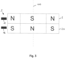
- FIG 3 shows a further example of the steering angle sensor unit 1, which is not part of the invention.
- Two multipole magnet rings 2,20 are provided, which have an equal number of pole pairs that are evenly distributed over the circumference.
- the magnet rings 2,20 are offset from one another by one pole in the circumferential direction and otherwise congruent with the longitudinal axis of the sensor 100.
- Each magnet ring 2,20 generates its own magnetic field, which is measured by a respective sensor 15,16, preferably Hall sensors.
- the two sensors 15,16 preferably lie with their sensor surfaces in a plane parallel to the longitudinal axis of the sensor unit 100 and each centered to the corresponding multipole magnet ring 2,20.
- Figure 4 shows an electrical circuit diagram of the corresponding steering angle sensor unit.
- the distance between the two sensors 15,16 is so small that the interference field in the area of the two sensors 15,16 is homogeneous. Since the vector magnetic field generated by the two multipole magnet rings in the area of the sensitive sensor surface of the respective sensor 2,20 is parallel and in opposite directions, an interference component of an external interference field can be determined by subtracting the two signals. To do this, the two sensor signals are again separated into a tangential and a radial component. The components are each subtracted from one another in a simple microcontroller 17 and the interference-free, corrected angle of rotation is calculated using an arctan function.
Landscapes
- Engineering & Computer Science (AREA)
- Physics & Mathematics (AREA)
- General Physics & Mathematics (AREA)
- Chemical & Material Sciences (AREA)
- Combustion & Propulsion (AREA)
- Transportation (AREA)
- Mechanical Engineering (AREA)
- Measurement Of Length, Angles, Or The Like Using Electric Or Magnetic Means (AREA)
- Power Steering Mechanism (AREA)
Claims (10)
- Une unité de capteur d'angle (1) pour mesurer un angle de rotation de la position de rotation d'un arbre de direction d'un véhicule à moteur comporte un anneau magnétique multipolaire (2) qui a un certain nombre de paires de pôles et peut être relié de manière étanche au couple à l'arbre de direction, deux capteurs de champ magnétique (4, 5) qui sont affectés à l'anneau magnétique multipolaire (2) et une unité d'évaluation qui est configurée pour déterminer un angle de rotation sur la base des signaux d'au moins deux capteurs de champ magnétique (4, 5), dans laquelle les deux capteurs de champ magnétique (4, 5) sont disposés de manière décalée dans la direction circonférentielle à l'extérieur de l'anneau magnétique multipolaire (2), de telle sorte qu'un champ magnétique provenant de l'anneau magnétique multipolaire (2), dans la zone des deux capteurs de champ magnétique (4, 5), a une valeur absolue approximativement égale mais des signes opposés, caractérisé en ce que l'unité de capteur d'angle possède en outre un anneau magnétique bipolaire avec un capteur de champ magnétique affecté pour la détermination absolue de l'angle de rotation, dans lequel l'anneau magnétique bipolaire est disposé à distance de l'anneau magnétique multipolaire dans la direction de l'axe longitudinal.
- L'unité de capteur d'angle selon la revendication 1, caractérisée par le fait que les capteurs de champ magnétique (4, 5) sont espacés d'une distance moins de 45° dans la direction circonférentielle.
- L'unité de capteur d'angle selon la revendication 1 ou 2, caractérisée par le fait que les capteurs de champ magnétique (4, 5) sont espacés d'une distance moins de 20° dans la direction circonférentielle.
- L'unité de capteur d'angle selon l'une des revendications précédentes, caractérisée par le fait que les capteurs de champ magnétique (4, 5) sont disposés en décalage d'un pôle dans la direction circonférentielle.
- L'unité de capteur d'angle selon l'une des revendications précédentes, caractérisée par le fait que les faces sensibles (40, 50) des capteurs de champ magnétique (4, 5) sont dans un plan et sont espacées d'une distance comprise entre 40% et 90% du diamètre de l'anneau magnétique multipolaire (2).
- L'unité de détection d'angle selon l'une des revendications précédentes, caractérisée en ce que l'unité d'évaluation est configurée pour déterminer un angle de rotation indépendamment d'un champ magnétique perturbateur externe, en formant des différences entre les signaux des deux capteurs de champ magnétique (4, 5).
- Système de direction assistée électromécanique pour un véhicule automobile, comprenant un arbre de direction pivotant autour d'un axe de rotation de l'arbre de direction et pouvant prendre différentes positions de rotation, un moteur électrique pour assister un mouvement de direction et une unité de capteur d'angle (1) telle que revendiquée dans l'une des revendications 1 à 6.
- Système de direction à commande électrique pour véhicules automobiles comportant un actionneur de direction qui agit sur les roues directrices et est régulé électroniquement en fonction de la demande du conducteur concernant le volant, un actionneur de rétroaction qui transmet les réactions de la route à un volant, une unité de commande qui contrôle l'actionneur de rétroaction et l'actionneur de direction, et une unité de capteur d'angle (1) comme indiqué dans l'une des revendications 1 à 6.
- Procédé de détermination d'un angle de rotation de la position de rotation d'un arbre de direction monté rotatif d'un véhicule à moteur avec une unité de capteur d'angle comportant un anneau magnétique multipolaire (2) ayant un certain nombre de paires de pôles et pouvant être relié de manière étanche au couple à l'arbre de direction, un premier et un second capteur de champ magnétique (4, 5) affectés à l'anneau magnétique multipolaire (2), et une unité d'évaluation configurée pour déterminer un angle de rotation sur la base des signaux des deux capteurs de champ magnétique (4, 5), comportant en outre un anneau magnétique bipolaire avec un capteur de champ magnétique affecté pour la détermination absolue de l'angle de rotation, dans lequel l'anneau magnétique bipolaire est disposé à l'écart de l'anneau magnétique multipolaire dans la direction de l'axe longitudinal, et dans lequel les deux capteurs de champ magnétique (4, 5) sont disposés de manière décalée dans la direction circonférentielle à l'extérieur de l'anneau magnétique multipolaire (2), et le procédé comprend les étapes suivantes:• en introduisant l'unité de détection d'angle dans un champ d'interférence magnétique,• disposer les deux capteurs de champ magnétique (4, 5) sur le côté extérieur de l'anneau magnétique multipolaire (2) de telle sorte que le champ d'interférence magnétique soit approximativement homogène dans la région des deux capteurs de champ magnétique (4, 5) et qu'un champ magnétique provenant de l'anneau magnétique multipolaire (2) ait, dans la région des deux capteurs de champ magnétique (4, 5), une valeur absolue approximativement égale, mais des signes opposés,• mesurer un champ magnétique au moyen du premier capteur de champ magnétique (4),• mesurer un champ magnétique au moyen du deuxième capteur de champ magnétique (5),• décomposition des deux signaux mesurés en composantes radiale et tangentielle (41,42,51,52),• former une différence entre les deux composantes radiales (61) et les deux composantes tangentielles (72), une pondération particulière pouvant être effectuée lors de la formation des différences,• déterminer l'angle de rotation indépendamment d'un champ d'interférence magnétique externe au moyen d'une fonction arctan (9), et• effectuer la détermination absolue de l'angle de rotation en utilisant l'anneau magnétique bipolaire avec le capteur de champ magnétique assigné.
- Procédé selon la revendication 9, caractérisé par le fait que les capteurs de champ magnétique (4, 5) sont décalés d'un pôle dans la direction circonférentielle.
Applications Claiming Priority (2)
| Application Number | Priority Date | Filing Date | Title |
|---|---|---|---|
| DE102018129487.5A DE102018129487A1 (de) | 2018-11-22 | 2018-11-22 | Winkelsensor mit mehrpoligem Magnet für eine Kraftfahrzeuglenkung |
| PCT/EP2019/082097 WO2020104593A2 (fr) | 2018-11-22 | 2019-11-21 | Capteur d'angle à aimant multipolaire pour un système de direction de véhicule automobile |
Publications (2)
| Publication Number | Publication Date |
|---|---|
| EP3884239A2 EP3884239A2 (fr) | 2021-09-29 |
| EP3884239B1 true EP3884239B1 (fr) | 2024-04-24 |
Family
ID=68766708
Family Applications (1)
| Application Number | Title | Priority Date | Filing Date |
|---|---|---|---|
| EP19813430.6A Active EP3884239B1 (fr) | 2018-11-22 | 2019-11-21 | Capteur d'angle avec aimant multipole pour la direction d'un véhicule automobile |
Country Status (5)
| Country | Link |
|---|---|
| US (1) | US12195080B2 (fr) |
| EP (1) | EP3884239B1 (fr) |
| CN (1) | CN113167598A (fr) |
| DE (1) | DE102018129487A1 (fr) |
| WO (1) | WO2020104593A2 (fr) |
Families Citing this family (10)
| Publication number | Priority date | Publication date | Assignee | Title |
|---|---|---|---|---|
| DE102020100297B4 (de) * | 2020-01-09 | 2023-01-19 | Schaeffler Technologies AG & Co. KG | Stromsensor und elektrisches System mit dem Stromsensor |
| DE102020210617A1 (de) * | 2020-08-20 | 2022-02-24 | Infineon Technologies Ag | Magnetfeldbasiertes winkelsensorsystem mit streufeldkompensation und verfahren zur streufeldkompensation |
| GB2601130B (en) * | 2020-11-18 | 2023-01-11 | Longvale Ltd | Sensor assembly |
| US11982526B2 (en) * | 2021-06-21 | 2024-05-14 | Infineon Technologies Ag | Safety mechanism for high availability angle sensor |
| EP4495552A3 (fr) * | 2021-11-25 | 2025-04-23 | Melexis Technologies SA | Capteur de position avec voies maitresses et nonius |
| DE102022200090A1 (de) | 2022-01-06 | 2023-07-06 | Volkswagen Aktiengesellschaft | Steer-by-wire-Lenksystem für ein Kraftfahrzeug |
| EP4235108B1 (fr) | 2022-02-25 | 2024-07-17 | Melexis Technologies SA | Système de capteur de position magnétique à haute précision |
| DE102023116302A1 (de) * | 2023-06-21 | 2024-12-24 | elobau GmbH & Co.KG | Verfahren zur Messung einer Position eines Magneten durch eine Sensor-Anordnung mit einer erhöhten magnetischen Fremdfeld-Robustheit unter Berücksichtigung des Signal-Rausch-Verhältnisses |
| BE1032017B1 (de) * | 2023-09-29 | 2025-04-28 | Thyssenkrupp Presta Ag | Steer-by-Wire-Lenksystem, Kraftfahrzeug und Verfahren zum Bestimmen eines absoluten Lenkwinkels |
| DE102024206776A1 (de) * | 2024-07-18 | 2026-01-22 | Robert Bosch Gesellschaft mit beschränkter Haftung | Lenkgetriebe mit einem hochintegrierten Lenkwinkelsensor und Verfahren zum Betreiben desselben |
Family Cites Families (31)
| Publication number | Priority date | Publication date | Assignee | Title |
|---|---|---|---|---|
| JPS5924970Y2 (ja) * | 1979-07-10 | 1984-07-23 | 株式会社デンソー | 回転位置検出装置 |
| JPH0665550B2 (ja) * | 1986-01-08 | 1994-08-24 | 株式会社日立製作所 | パワ−ステアリング制御装置 |
| US5568048A (en) * | 1994-12-14 | 1996-10-22 | General Motors Corporation | Three sensor rotational position and displacement detection apparatus with common mode noise rejection |
| US5680042A (en) * | 1994-12-30 | 1997-10-21 | Lake Shore Cryotronics, Inc. | Magnetoresistive sensor with reduced output signal jitter |
| DE19908361A1 (de) * | 1999-02-26 | 2000-09-21 | Klemens Gintner | Sensorvorrichtung zur Erfassung von Geschwindigkeit und Bewegungsrichtung eines Objektes, insbesondere von Drehzahl und -richtung eines rotierenden Objektes |
| AU775247B2 (en) * | 1999-12-06 | 2004-07-22 | Robert Bosch Gmbh | Device for measuring the angle and/or the angular velocity of a rotatable body and/or the torque acting upon said body |
| DE10042006A1 (de) * | 2000-08-26 | 2002-03-07 | Bosch Gmbh Robert | Vorrichtung und Verfahren zur Winkelmessung |
| DE10210372A1 (de) * | 2002-03-08 | 2003-09-25 | Siemens Ag | Drehwinkelsensor mit hoher Winkelauflösung |
| DE10331580A1 (de) * | 2003-07-11 | 2005-01-27 | Robert Bosch Gmbh | Vorrichtung zur Detektion der Drehzahl und/oder der Position eines rotierenden Bauteils |
| DE102004004024A1 (de) * | 2004-01-20 | 2004-11-18 | Valeo Schalter Und Sensoren Gmbh | Lenkwinkelsensor |
| WO2006085499A1 (fr) * | 2005-02-10 | 2006-08-17 | Matsushita Electric Industrial Co., Ltd. | Dispositif detecteur d'angle de rotation et de couple |
| EP1777501A1 (fr) * | 2005-10-24 | 2007-04-25 | Getrag Ford Transmissions GmbH | Agencement de capteurs de position destiné à la détermination de position sans contact à l aide d'éléments de capteur magnétiquement sensibles redondants |
| FR2893410B1 (fr) | 2005-11-15 | 2008-12-05 | Moving Magnet Tech Mmt | Capteur de position angulaire magnetique pour une course allant jusqu'a 360 |
| FR2904412B1 (fr) * | 2006-07-27 | 2008-10-17 | Snr Roulements Sa | Procede de determination de deux signaux en quadrature |
| US7502119B2 (en) * | 2007-01-29 | 2009-03-10 | Filmetrics, Inc. | Thin-film metrology using spectral reflectance with an intermediate in-line reference |
| JP4254868B2 (ja) * | 2007-01-31 | 2009-04-15 | 日立金属株式会社 | 磁気センサ及びこれを用いた磁気エンコーダ |
| FR2923903B1 (fr) * | 2007-11-20 | 2010-01-08 | Moving Magnet Tech | Capteur de position magnetique angulaire ou lineaire presentant une insensibilite aux champs exterieurs |
| DE102008043265A1 (de) | 2008-10-29 | 2010-05-06 | Zf Lenksysteme Gmbh | Verfahren und Vorrichtung zur Fehlerkompensation bei elektronischen Winkelmessungen |
| JP5062450B2 (ja) | 2010-08-11 | 2012-10-31 | Tdk株式会社 | 回転磁界センサ |
| FR2965347B1 (fr) * | 2010-09-29 | 2015-04-03 | Moving Magnet Tech | Capteur de position ameliore |
| DE102011079962A1 (de) | 2011-07-28 | 2013-01-31 | Robert Bosch Gmbh | Elektromotor mit einem Rotorpositionssensor |
| US9208134B2 (en) | 2012-01-10 | 2015-12-08 | King Abdulaziz City For Science And Technology | Methods and systems for tokenizing multilingual textual documents |
| JP2014142322A (ja) * | 2012-12-27 | 2014-08-07 | Jtekt Corp | 回転角検出装置 |
| JP2014199182A (ja) * | 2013-03-29 | 2014-10-23 | Tdk株式会社 | 磁気センサシステム |
| JP2014199184A (ja) * | 2013-03-29 | 2014-10-23 | Tdk株式会社 | 磁気センサシステム |
| DE202014002597U1 (de) | 2014-03-26 | 2014-06-12 | Balluff Gmbh | Magnetring und Positionssensor |
| US9618365B2 (en) * | 2014-09-02 | 2017-04-11 | Infineon Technologies Ag | Angle sensor system having a magnetic sensor |
| DE102016108846B4 (de) * | 2016-05-12 | 2024-05-08 | Infineon Technologies Ag | Winkelsensoranordnung und Verfahren für die Winkelsensoranordnung |
| WO2018008628A1 (fr) * | 2016-07-05 | 2018-01-11 | 日本精工株式会社 | Dispositif de détection et dispositif de direction assistée par voie électrique |
| JP6288482B1 (ja) | 2016-09-28 | 2018-03-07 | Tdk株式会社 | 角度センサおよび角度センサシステム |
| JP6323699B1 (ja) | 2017-03-22 | 2018-05-16 | Tdk株式会社 | 角度センサおよび角度センサシステム |
-
2018
- 2018-11-22 DE DE102018129487.5A patent/DE102018129487A1/de not_active Withdrawn
-
2019
- 2019-11-21 US US17/293,679 patent/US12195080B2/en active Active
- 2019-11-21 WO PCT/EP2019/082097 patent/WO2020104593A2/fr not_active Ceased
- 2019-11-21 CN CN201980076592.6A patent/CN113167598A/zh active Pending
- 2019-11-21 EP EP19813430.6A patent/EP3884239B1/fr active Active
Also Published As
| Publication number | Publication date |
|---|---|
| WO2020104593A3 (fr) | 2020-07-16 |
| CN113167598A (zh) | 2021-07-23 |
| WO2020104593A2 (fr) | 2020-05-28 |
| DE102018129487A1 (de) | 2020-05-28 |
| US20220001924A1 (en) | 2022-01-06 |
| EP3884239A2 (fr) | 2021-09-29 |
| US12195080B2 (en) | 2025-01-14 |
Similar Documents
| Publication | Publication Date | Title |
|---|---|---|
| EP3884239B1 (fr) | Capteur d'angle avec aimant multipole pour la direction d'un véhicule automobile | |
| DE112008003911B4 (de) | Magnetischer Encoder und Aktuator | |
| DE68917191T2 (de) | Gerät zur Drehmomentdetektion mit Fehlersignal. | |
| EP2979102B1 (fr) | Capteur à effet hall insensible aux champs magnétiques extérieurs | |
| EP3029427B1 (fr) | Dispositif et algorithme destines a la determination d'angle mecanique radial absolu d'un arbre | |
| DE102010040584B4 (de) | Verfahren und Vorrichtung zur Störfeldkompensation von magnetischen Winkelsensoren | |
| DE102015117763B4 (de) | Vorrichtung und Verfahren zur Bestimmung eines Drehwinkels eines Rotors | |
| DE102011055000A1 (de) | Drehwinkelerfassungseinrichtung und elektrische Lenkhilfevorrichtung, welche dieselbe verwendet | |
| EP2764340B1 (fr) | Ensemble de detection | |
| EP3601955B1 (fr) | Dispositif capteur d'angle à compensation des champs parasites et procédé de détermination d'angle à compensation des champs parasites | |
| DE102013224098A1 (de) | Sensoranordnung zur Erfassung von Drehwinkeln an einem rotierenden Bauteil in einem Fahrzeug | |
| DE102017222676A1 (de) | Wegsensor | |
| WO2014086525A1 (fr) | Dispositif à capteur pour la détermination d'au moins une propriété de rotation d'un élément en rotation | |
| DE102018115099A1 (de) | Drehwinkelgeber | |
| DE102018211216A1 (de) | Geberradanordnung und Verfahren zum Ermitteln einer Absolutwinkelposition und einer Drehrichtung | |
| DE102017111979A1 (de) | Winkelsensor, Korrekturverfahren zur Verwendung mit dem Winkelsensor und Winkelsensorsystem | |
| WO2007014599A1 (fr) | Dispositif pour detecter des rotations d'un arbre de direction | |
| DE102012016287B4 (de) | Verfahren und Wellenlagebestimmungsvorrichtung zum Bestimmen einer Drehposition einer Welle | |
| DE102016103518B4 (de) | Verfahren und Vorrichtung zur Rotorlagendiagnose in einem elektromotorischen Antrieb | |
| DE102017223091A1 (de) | Geberradanordnung und Verfahren zum Ermitteln einer Absolutwinkelposition und einer Drehrichtung | |
| DE102018200234A1 (de) | Sensorsystem zur Bestimmung mindestens einer Rotationseigenschaft eines rotierenden Elements | |
| EP3312566B1 (fr) | Transducteur rotatif destiné à mesurer une variable d'état d'un objet rotatif | |
| WO2019110183A1 (fr) | Ensemble capteur destiné à déterminer au moins une caractéristique de rotation d'un élément en rotation autour d'au moins un axe de rotation | |
| DE102019119672A1 (de) | Korrekturvorrichtung für einen winkelsensor und winkelsensor | |
| DE102014224295B3 (de) | Winkelgeber und Anordnung zur Ermittlung von Unwucht und/oder Last |
Legal Events
| Date | Code | Title | Description |
|---|---|---|---|
| STAA | Information on the status of an ep patent application or granted ep patent |
Free format text: STATUS: UNKNOWN |
|
| STAA | Information on the status of an ep patent application or granted ep patent |
Free format text: STATUS: THE INTERNATIONAL PUBLICATION HAS BEEN MADE |
|
| PUAI | Public reference made under article 153(3) epc to a published international application that has entered the european phase |
Free format text: ORIGINAL CODE: 0009012 |
|
| STAA | Information on the status of an ep patent application or granted ep patent |
Free format text: STATUS: REQUEST FOR EXAMINATION WAS MADE |
|
| 17P | Request for examination filed |
Effective date: 20210622 |
|
| AK | Designated contracting states |
Kind code of ref document: A2 Designated state(s): AL AT BE BG CH CY CZ DE DK EE ES FI FR GB GR HR HU IE IS IT LI LT LU LV MC MK MT NL NO PL PT RO RS SE SI SK SM TR |
|
| DAV | Request for validation of the european patent (deleted) | ||
| DAX | Request for extension of the european patent (deleted) | ||
| STAA | Information on the status of an ep patent application or granted ep patent |
Free format text: STATUS: EXAMINATION IS IN PROGRESS |
|
| 17Q | First examination report despatched |
Effective date: 20221129 |
|
| GRAP | Despatch of communication of intention to grant a patent |
Free format text: ORIGINAL CODE: EPIDOSNIGR1 |
|
| STAA | Information on the status of an ep patent application or granted ep patent |
Free format text: STATUS: GRANT OF PATENT IS INTENDED |
|
| RIC1 | Information provided on ipc code assigned before grant |
Ipc: B62D 15/02 20060101ALI20230911BHEP Ipc: G01D 5/244 20060101ALI20230911BHEP Ipc: G01D 5/14 20060101AFI20230911BHEP |
|
| INTG | Intention to grant announced |
Effective date: 20230929 |
|
| GRAJ | Information related to disapproval of communication of intention to grant by the applicant or resumption of examination proceedings by the epo deleted |
Free format text: ORIGINAL CODE: EPIDOSDIGR1 |
|
| STAA | Information on the status of an ep patent application or granted ep patent |
Free format text: STATUS: EXAMINATION IS IN PROGRESS |
|
| GRAP | Despatch of communication of intention to grant a patent |
Free format text: ORIGINAL CODE: EPIDOSNIGR1 |
|
| STAA | Information on the status of an ep patent application or granted ep patent |
Free format text: STATUS: GRANT OF PATENT IS INTENDED |
|
| INTC | Intention to grant announced (deleted) | ||
| INTG | Intention to grant announced |
Effective date: 20240104 |
|
| GRAS | Grant fee paid |
Free format text: ORIGINAL CODE: EPIDOSNIGR3 |
|
| GRAA | (expected) grant |
Free format text: ORIGINAL CODE: 0009210 |
|
| STAA | Information on the status of an ep patent application or granted ep patent |
Free format text: STATUS: THE PATENT HAS BEEN GRANTED |
|
| AK | Designated contracting states |
Kind code of ref document: B1 Designated state(s): AL AT BE BG CH CY CZ DE DK EE ES FI FR GB GR HR HU IE IS IT LI LT LU LV MC MK MT NL NO PL PT RO RS SE SI SK SM TR |
|
| REG | Reference to a national code |
Ref country code: GB Ref legal event code: FG4D Free format text: NOT ENGLISH |
|
| REG | Reference to a national code |
Ref country code: CH Ref legal event code: EP |
|
| REG | Reference to a national code |
Ref country code: DE Ref legal event code: R096 Ref document number: 502019011137 Country of ref document: DE |
|
| REG | Reference to a national code |
Ref country code: IE Ref legal event code: FG4D Free format text: LANGUAGE OF EP DOCUMENT: GERMAN |
|
| REG | Reference to a national code |
Ref country code: DE Ref legal event code: R084 Ref document number: 502019011137 Country of ref document: DE |
|
| REG | Reference to a national code |
Ref country code: LT Ref legal event code: MG9D |
|
| REG | Reference to a national code |
Ref country code: NL Ref legal event code: MP Effective date: 20240424 |
|
| PG25 | Lapsed in a contracting state [announced via postgrant information from national office to epo] |
Ref country code: NL Free format text: LAPSE BECAUSE OF FAILURE TO SUBMIT A TRANSLATION OF THE DESCRIPTION OR TO PAY THE FEE WITHIN THE PRESCRIBED TIME-LIMIT Effective date: 20240424 |
|
| PG25 | Lapsed in a contracting state [announced via postgrant information from national office to epo] |
Ref country code: NL Free format text: LAPSE BECAUSE OF FAILURE TO SUBMIT A TRANSLATION OF THE DESCRIPTION OR TO PAY THE FEE WITHIN THE PRESCRIBED TIME-LIMIT Effective date: 20240424 |
|
| PG25 | Lapsed in a contracting state [announced via postgrant information from national office to epo] |
Ref country code: IS Free format text: LAPSE BECAUSE OF FAILURE TO SUBMIT A TRANSLATION OF THE DESCRIPTION OR TO PAY THE FEE WITHIN THE PRESCRIBED TIME-LIMIT Effective date: 20240824 |
|
| PG25 | Lapsed in a contracting state [announced via postgrant information from national office to epo] |
Ref country code: BG Free format text: LAPSE BECAUSE OF FAILURE TO SUBMIT A TRANSLATION OF THE DESCRIPTION OR TO PAY THE FEE WITHIN THE PRESCRIBED TIME-LIMIT Effective date: 20240424 |
|
| PG25 | Lapsed in a contracting state [announced via postgrant information from national office to epo] |
Ref country code: FI Free format text: LAPSE BECAUSE OF FAILURE TO SUBMIT A TRANSLATION OF THE DESCRIPTION OR TO PAY THE FEE WITHIN THE PRESCRIBED TIME-LIMIT Effective date: 20240424 Ref country code: HR Free format text: LAPSE BECAUSE OF FAILURE TO SUBMIT A TRANSLATION OF THE DESCRIPTION OR TO PAY THE FEE WITHIN THE PRESCRIBED TIME-LIMIT Effective date: 20240424 |
|
| PG25 | Lapsed in a contracting state [announced via postgrant information from national office to epo] |
Ref country code: GR Free format text: LAPSE BECAUSE OF FAILURE TO SUBMIT A TRANSLATION OF THE DESCRIPTION OR TO PAY THE FEE WITHIN THE PRESCRIBED TIME-LIMIT Effective date: 20240725 |
|
| PG25 | Lapsed in a contracting state [announced via postgrant information from national office to epo] |
Ref country code: PT Free format text: LAPSE BECAUSE OF FAILURE TO SUBMIT A TRANSLATION OF THE DESCRIPTION OR TO PAY THE FEE WITHIN THE PRESCRIBED TIME-LIMIT Effective date: 20240826 |
|
| PG25 | Lapsed in a contracting state [announced via postgrant information from national office to epo] |
Ref country code: ES Free format text: LAPSE BECAUSE OF FAILURE TO SUBMIT A TRANSLATION OF THE DESCRIPTION OR TO PAY THE FEE WITHIN THE PRESCRIBED TIME-LIMIT Effective date: 20240424 |
|
| PG25 | Lapsed in a contracting state [announced via postgrant information from national office to epo] |
Ref country code: PL Free format text: LAPSE BECAUSE OF FAILURE TO SUBMIT A TRANSLATION OF THE DESCRIPTION OR TO PAY THE FEE WITHIN THE PRESCRIBED TIME-LIMIT Effective date: 20240424 |
|
| PG25 | Lapsed in a contracting state [announced via postgrant information from national office to epo] |
Ref country code: LV Free format text: LAPSE BECAUSE OF FAILURE TO SUBMIT A TRANSLATION OF THE DESCRIPTION OR TO PAY THE FEE WITHIN THE PRESCRIBED TIME-LIMIT Effective date: 20240424 |
|
| PG25 | Lapsed in a contracting state [announced via postgrant information from national office to epo] |
Ref country code: PT Free format text: LAPSE BECAUSE OF FAILURE TO SUBMIT A TRANSLATION OF THE DESCRIPTION OR TO PAY THE FEE WITHIN THE PRESCRIBED TIME-LIMIT Effective date: 20240826 Ref country code: PL Free format text: LAPSE BECAUSE OF FAILURE TO SUBMIT A TRANSLATION OF THE DESCRIPTION OR TO PAY THE FEE WITHIN THE PRESCRIBED TIME-LIMIT Effective date: 20240424 Ref country code: NO Free format text: LAPSE BECAUSE OF FAILURE TO SUBMIT A TRANSLATION OF THE DESCRIPTION OR TO PAY THE FEE WITHIN THE PRESCRIBED TIME-LIMIT Effective date: 20240724 Ref country code: LV Free format text: LAPSE BECAUSE OF FAILURE TO SUBMIT A TRANSLATION OF THE DESCRIPTION OR TO PAY THE FEE WITHIN THE PRESCRIBED TIME-LIMIT Effective date: 20240424 Ref country code: IS Free format text: LAPSE BECAUSE OF FAILURE TO SUBMIT A TRANSLATION OF THE DESCRIPTION OR TO PAY THE FEE WITHIN THE PRESCRIBED TIME-LIMIT Effective date: 20240824 Ref country code: HR Free format text: LAPSE BECAUSE OF FAILURE TO SUBMIT A TRANSLATION OF THE DESCRIPTION OR TO PAY THE FEE WITHIN THE PRESCRIBED TIME-LIMIT Effective date: 20240424 Ref country code: GR Free format text: LAPSE BECAUSE OF FAILURE TO SUBMIT A TRANSLATION OF THE DESCRIPTION OR TO PAY THE FEE WITHIN THE PRESCRIBED TIME-LIMIT Effective date: 20240725 Ref country code: FI Free format text: LAPSE BECAUSE OF FAILURE TO SUBMIT A TRANSLATION OF THE DESCRIPTION OR TO PAY THE FEE WITHIN THE PRESCRIBED TIME-LIMIT Effective date: 20240424 Ref country code: ES Free format text: LAPSE BECAUSE OF FAILURE TO SUBMIT A TRANSLATION OF THE DESCRIPTION OR TO PAY THE FEE WITHIN THE PRESCRIBED TIME-LIMIT Effective date: 20240424 Ref country code: BG Free format text: LAPSE BECAUSE OF FAILURE TO SUBMIT A TRANSLATION OF THE DESCRIPTION OR TO PAY THE FEE WITHIN THE PRESCRIBED TIME-LIMIT Effective date: 20240424 Ref country code: RS Free format text: LAPSE BECAUSE OF FAILURE TO SUBMIT A TRANSLATION OF THE DESCRIPTION OR TO PAY THE FEE WITHIN THE PRESCRIBED TIME-LIMIT Effective date: 20240724 |
|
| PG25 | Lapsed in a contracting state [announced via postgrant information from national office to epo] |
Ref country code: DK Free format text: LAPSE BECAUSE OF FAILURE TO SUBMIT A TRANSLATION OF THE DESCRIPTION OR TO PAY THE FEE WITHIN THE PRESCRIBED TIME-LIMIT Effective date: 20240424 |
|
| PG25 | Lapsed in a contracting state [announced via postgrant information from national office to epo] |
Ref country code: EE Free format text: LAPSE BECAUSE OF FAILURE TO SUBMIT A TRANSLATION OF THE DESCRIPTION OR TO PAY THE FEE WITHIN THE PRESCRIBED TIME-LIMIT Effective date: 20240424 |
|
| PG25 | Lapsed in a contracting state [announced via postgrant information from national office to epo] |
Ref country code: CZ Free format text: LAPSE BECAUSE OF FAILURE TO SUBMIT A TRANSLATION OF THE DESCRIPTION OR TO PAY THE FEE WITHIN THE PRESCRIBED TIME-LIMIT Effective date: 20240424 |
|
| PG25 | Lapsed in a contracting state [announced via postgrant information from national office to epo] |
Ref country code: SK Free format text: LAPSE BECAUSE OF FAILURE TO SUBMIT A TRANSLATION OF THE DESCRIPTION OR TO PAY THE FEE WITHIN THE PRESCRIBED TIME-LIMIT Effective date: 20240424 Ref country code: RO Free format text: LAPSE BECAUSE OF FAILURE TO SUBMIT A TRANSLATION OF THE DESCRIPTION OR TO PAY THE FEE WITHIN THE PRESCRIBED TIME-LIMIT Effective date: 20240424 |
|
| REG | Reference to a national code |
Ref country code: DE Ref legal event code: R097 Ref document number: 502019011137 Country of ref document: DE |
|
| PG25 | Lapsed in a contracting state [announced via postgrant information from national office to epo] |
Ref country code: SM Free format text: LAPSE BECAUSE OF FAILURE TO SUBMIT A TRANSLATION OF THE DESCRIPTION OR TO PAY THE FEE WITHIN THE PRESCRIBED TIME-LIMIT Effective date: 20240424 |
|
| PG25 | Lapsed in a contracting state [announced via postgrant information from national office to epo] |
Ref country code: SM Free format text: LAPSE BECAUSE OF FAILURE TO SUBMIT A TRANSLATION OF THE DESCRIPTION OR TO PAY THE FEE WITHIN THE PRESCRIBED TIME-LIMIT Effective date: 20240424 Ref country code: SK Free format text: LAPSE BECAUSE OF FAILURE TO SUBMIT A TRANSLATION OF THE DESCRIPTION OR TO PAY THE FEE WITHIN THE PRESCRIBED TIME-LIMIT Effective date: 20240424 Ref country code: RO Free format text: LAPSE BECAUSE OF FAILURE TO SUBMIT A TRANSLATION OF THE DESCRIPTION OR TO PAY THE FEE WITHIN THE PRESCRIBED TIME-LIMIT Effective date: 20240424 Ref country code: EE Free format text: LAPSE BECAUSE OF FAILURE TO SUBMIT A TRANSLATION OF THE DESCRIPTION OR TO PAY THE FEE WITHIN THE PRESCRIBED TIME-LIMIT Effective date: 20240424 Ref country code: DK Free format text: LAPSE BECAUSE OF FAILURE TO SUBMIT A TRANSLATION OF THE DESCRIPTION OR TO PAY THE FEE WITHIN THE PRESCRIBED TIME-LIMIT Effective date: 20240424 Ref country code: CZ Free format text: LAPSE BECAUSE OF FAILURE TO SUBMIT A TRANSLATION OF THE DESCRIPTION OR TO PAY THE FEE WITHIN THE PRESCRIBED TIME-LIMIT Effective date: 20240424 |
|
| PLBE | No opposition filed within time limit |
Free format text: ORIGINAL CODE: 0009261 |
|
| STAA | Information on the status of an ep patent application or granted ep patent |
Free format text: STATUS: NO OPPOSITION FILED WITHIN TIME LIMIT |
|
| 26N | No opposition filed |
Effective date: 20250127 |
|
| PG25 | Lapsed in a contracting state [announced via postgrant information from national office to epo] |
Ref country code: SI Free format text: LAPSE BECAUSE OF FAILURE TO SUBMIT A TRANSLATION OF THE DESCRIPTION OR TO PAY THE FEE WITHIN THE PRESCRIBED TIME-LIMIT Effective date: 20240424 |
|
| REG | Reference to a national code |
Ref country code: CH Ref legal event code: PL |
|
| PG25 | Lapsed in a contracting state [announced via postgrant information from national office to epo] |
Ref country code: MC Free format text: LAPSE BECAUSE OF FAILURE TO SUBMIT A TRANSLATION OF THE DESCRIPTION OR TO PAY THE FEE WITHIN THE PRESCRIBED TIME-LIMIT Effective date: 20240424 |
|
| PG25 | Lapsed in a contracting state [announced via postgrant information from national office to epo] |
Ref country code: LU Free format text: LAPSE BECAUSE OF NON-PAYMENT OF DUE FEES Effective date: 20241121 |
|
| REG | Reference to a national code |
Ref country code: CH Ref legal event code: PL |
|
| GBPC | Gb: european patent ceased through non-payment of renewal fee |
Effective date: 20241121 |
|
| PG25 | Lapsed in a contracting state [announced via postgrant information from national office to epo] |
Ref country code: CH Free format text: LAPSE BECAUSE OF NON-PAYMENT OF DUE FEES Effective date: 20241130 |
|
| REG | Reference to a national code |
Ref country code: BE Ref legal event code: MM Effective date: 20241130 |
|
| PG25 | Lapsed in a contracting state [announced via postgrant information from national office to epo] |
Ref country code: SE Free format text: LAPSE BECAUSE OF FAILURE TO SUBMIT A TRANSLATION OF THE DESCRIPTION OR TO PAY THE FEE WITHIN THE PRESCRIBED TIME-LIMIT Effective date: 20240424 |
|
| PG25 | Lapsed in a contracting state [announced via postgrant information from national office to epo] |
Ref country code: GB Free format text: LAPSE BECAUSE OF NON-PAYMENT OF DUE FEES Effective date: 20241121 Ref country code: BE Free format text: LAPSE BECAUSE OF NON-PAYMENT OF DUE FEES Effective date: 20241130 |
|
| PG25 | Lapsed in a contracting state [announced via postgrant information from national office to epo] |
Ref country code: FR Free format text: LAPSE BECAUSE OF NON-PAYMENT OF DUE FEES Effective date: 20241130 |
|
| PG25 | Lapsed in a contracting state [announced via postgrant information from national office to epo] |
Ref country code: IE Free format text: LAPSE BECAUSE OF NON-PAYMENT OF DUE FEES Effective date: 20241121 |
|
| PGFP | Annual fee paid to national office [announced via postgrant information from national office to epo] |
Ref country code: DE Payment date: 20251119 Year of fee payment: 7 |
|
| PG25 | Lapsed in a contracting state [announced via postgrant information from national office to epo] |
Ref country code: AT Free format text: LAPSE BECAUSE OF NON-PAYMENT OF DUE FEES Effective date: 20241121 |
|
| REG | Reference to a national code |
Ref country code: AT Ref legal event code: MM01 Ref document number: 1680040 Country of ref document: AT Kind code of ref document: T Effective date: 20241121 |
|
| PG25 | Lapsed in a contracting state [announced via postgrant information from national office to epo] |
Ref country code: IT Free format text: LAPSE BECAUSE OF FAILURE TO SUBMIT A TRANSLATION OF THE DESCRIPTION OR TO PAY THE FEE WITHIN THE PRESCRIBED TIME-LIMIT Effective date: 20240424 |
|
| PG25 | Lapsed in a contracting state [announced via postgrant information from national office to epo] |
Ref country code: HU Free format text: LAPSE BECAUSE OF FAILURE TO SUBMIT A TRANSLATION OF THE DESCRIPTION OR TO PAY THE FEE WITHIN THE PRESCRIBED TIME-LIMIT; INVALID AB INITIO Effective date: 20191121 |
|
| PG25 | Lapsed in a contracting state [announced via postgrant information from national office to epo] |
Ref country code: CY Free format text: LAPSE BECAUSE OF FAILURE TO SUBMIT A TRANSLATION OF THE DESCRIPTION OR TO PAY THE FEE WITHIN THE PRESCRIBED TIME-LIMIT; INVALID AB INITIO Effective date: 20191121 |