EP3884751B1 - Mécanisme de déploiement et système hydraulique pour tondeuse agricole - Google Patents
Mécanisme de déploiement et système hydraulique pour tondeuse agricole Download PDFInfo
- Publication number
- EP3884751B1 EP3884751B1 EP21164719.3A EP21164719A EP3884751B1 EP 3884751 B1 EP3884751 B1 EP 3884751B1 EP 21164719 A EP21164719 A EP 21164719A EP 3884751 B1 EP3884751 B1 EP 3884751B1
- Authority
- EP
- European Patent Office
- Prior art keywords
- frame
- transport
- trail
- actuator
- tongue
- Prior art date
- Legal status (The legal status is an assumption and is not a legal conclusion. Google has not performed a legal analysis and makes no representation as to the accuracy of the status listed.)
- Active
Links
Images

Classifications
-
- A—HUMAN NECESSITIES
- A01—AGRICULTURE; FORESTRY; ANIMAL HUSBANDRY; HUNTING; TRAPPING; FISHING
- A01D—HARVESTING; MOWING
- A01D34/00—Mowers; Mowing apparatus of harvesters
- A01D34/01—Mowers; Mowing apparatus of harvesters characterised by features relating to the type of cutting apparatus
- A01D34/412—Mowers; Mowing apparatus of harvesters characterised by features relating to the type of cutting apparatus having rotating cutters
- A01D34/63—Mowers; Mowing apparatus of harvesters characterised by features relating to the type of cutting apparatus having rotating cutters having cutters rotating about a vertical axis
- A01D34/64—Mowers; Mowing apparatus of harvesters characterised by features relating to the type of cutting apparatus having rotating cutters having cutters rotating about a vertical axis mounted on a vehicle, e.g. a tractor, or drawn by an animal or a vehicle
- A01D34/66—Mowers; Mowing apparatus of harvesters characterised by features relating to the type of cutting apparatus having rotating cutters having cutters rotating about a vertical axis mounted on a vehicle, e.g. a tractor, or drawn by an animal or a vehicle with two or more cutters
- A01D34/664—Disc cutter bars
-
- A—HUMAN NECESSITIES
- A01—AGRICULTURE; FORESTRY; ANIMAL HUSBANDRY; HUNTING; TRAPPING; FISHING
- A01B—SOIL WORKING IN AGRICULTURE OR FORESTRY; PARTS, DETAILS, OR ACCESSORIES OF AGRICULTURAL MACHINES OR IMPLEMENTS, IN GENERAL
- A01B73/00—Means or arrangements to facilitate transportation of agricultural machines or implements, e.g. folding frames to reduce overall width
- A01B73/005—Means or arrangements to facilitate transportation of agricultural machines or implements, e.g. folding frames to reduce overall width for endwise transportation, i.e. the direction of transport being substantially perpendicular to the direction of agricultural operation
-
- A—HUMAN NECESSITIES
- A01—AGRICULTURE; FORESTRY; ANIMAL HUSBANDRY; HUNTING; TRAPPING; FISHING
- A01D—HARVESTING; MOWING
- A01D75/00—Accessories for harvesters or mowers
- A01D75/002—Carriers for the transport of harvesters or mowers
- A01D75/004—Carriers for the transport of harvesters or mowers for mowers
Definitions
- the present invention pertains to an agricultural mowing device and, more specifically, to a transport system for the agricultural mowing device.
- a farmer may use an agricultural mowing device, such as mower or mower conditioner, to cut crop material like hay or grass and deposit the cut crop material onto the field in windrows or swaths.
- an agricultural mowing device such as mower or mower conditioner
- the mowing device is towed behind an agricultural vehicle, such as a tractor.
- many mowing assemblies include a driving vehicle that pushes a mower conditioner in front of the vehicle while simultaneously pulling another mower conditioner behind the vehicle.
- a mower generally includes a tongue connectable to the tractor, a subframe, i.e., trail frame, a cutting device, and a transport system.
- a mower conditioner additionally includes conditioning rollers for conditioning the cut crop material.
- the mower can be variously configured as a disc, sickle, or drum mower wherein the cutting device includes a series of rotatable discs, a sickle bar, or a rotating drum, respectively.
- the disc cutter bar may generally include multiple juxtaposed cutterheads for cutting the standing crop. Each cutterhead may consist of a rotating disc with diametrically opposed cutting blades or knives affixed to the body of the disc.
- the transport system of a pull-behind mowing device is used to reduce the overall profile of the mowing device for transportation thereof.
- the width of the mowing device in its operating orientation prevents the towed transportation of the mowing device on farm lanes, roadways, or through gates.
- the transport system may include a separate transport trailer or an integrated transport subframe with transport wheels that selectively support the mowing device.
- the separate transport trailer may reorient the mowing device and carry the mowing device with its width extending along the longitudinal length of the transport trailer.
- the mowing device is arranged parallel to the forward direction of travel of the towing vehicle.
- Such transport trailers may be useful; however, these transport trailers may add significant cost to the overall mowing operation. For instance, such transport trailers must be separately purchased, maintained, and transported between the various fields and farm headquarters, which increases the operating cost of a mowing operation.
- Integrated transport systems typically include a pivotable subframe with wheels for selectively supporting the mower and multiple actuators for pivoting the mower to be parallel with the forward direction of travel of the towing vehicle.
- Such an integrated transport system is shown in EP2 656 712 .
- Integrated transport systems can be more convenient than separate transport trailers; however, the added components may significantly increase the overall weight of the mower package.
- the weight of the mowing device may be unevenly distributed amongst the transport wheels. For instance, in the transport position, a traditional integrated transport system may unevenly balance the weight of the cutter bar such that the right wheel may carry more weight, such as 1.5-2 times more weight, than the left wheel.
- an agricultural mowing device configured for being towed behind an agricultural vehicle.
- the agricultural mowing device is configurable in a field position for cutting a crop material in a field and a transport position for transporting the agricultural mowing device.
- the agricultural mowing device includes a tongue configured for connecting to the agricultural vehicle, a trail frame rotatably connected to the tongue, a cutter bar connected to the trail frame and configured for cutting the crop material in the field position, a first trail-frame wheel and a second trail-frame wheel each being rotatably connected to the trail frame and configured for supporting the trail frame in the field position, and a first lift actuator operably connected in between the trail frame and the first trail-frame wheel and a second lift actuator operably connected in between the trail frame and the second trail-frame wheel.
- the first lift actuator and the second lift actuator are configured for lifting the trail frame.
- the agricultural mowing device also includes a trail-frame actuating mechanism operably connected in between the tongue and the trail frame and configured for rotating the trail frame, and a transport system.
- the transport system includes a transport frame, a first transport wheel and a second transport wheel each being rotatably connected to the transport frame and configured for supporting the tongue in the transport position, and a transport actuating mechanism rotatably connecting the transport frame to the tongue.
- the transport actuating mechanism includes a linkage assembly rotatably connected to a side of the tongue, in between the transport frame and the tongue and a transport actuator operably connected in between the tongue and the transport frame and configured for rotating the transport frame.
- One possible advantage of the exemplary embodiment of the agricultural mowing device is that the hydraulic system protects against accidental operation of the transport system during a field or transport operation through the use of position-based sequence and check valves.
- Another possible advantage of the exemplary embodiment of the agricultural mowing device is that the hydraulic system ensures that the operator cannot swing the trail frame in the wrong direction during the final stage of transport deployment, which would otherwise cause the trail frame to contact the transport frame.
- trail-frame actuating mechanism is streamlined for efficiently rotating the trail frame due to its two opposing swing actuators being operably connected to the tongue via the same rotating link.
- forward when used in connection with the agricultural mower and/or components thereof are usually determined with reference to the direction of forward operative travel of the towing vehicle, but they should not be construed as limiting.
- longitudinal and “transverse” are determined with reference to the fore-and-aft direction of the towing vehicle and are equally not to be construed as limiting.
- an agricultural mowing assembly 100 that includes an agricultural vehicle 110 and an agricultural mowing device 120, which is towed by the agricultural vehicle 110 in a forward direction of travel F.
- the agricultural vehicle 110 generally includes a chassis, a prime mover, wheels and/or tracts, and a cab for housing the operator.
- the vehicle 110 can be in the form of any desired agricultural vehicle, such as a tractor or self-propelled windrower.
- the mowing device 120 may be in the form of a center pivot mower or mower conditioner 120. As shown, the mowing device 120 is in the form of a center pivot mower conditioner 120. However, the mowing device 120 may be in the form of any desired mowing device.
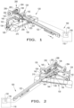
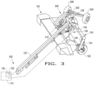
- the mowing device 120 is configurable in a field position for cutting a crop material in the field ( FIGS. 1-3 ) and a transport position for transporting the agricultural mowing device 120 ( FIG. 5 ).
- the mowing device 120 may also be positioned between various field positions, such as an intermediate field position ( FIG. 1 ), a full field left position ( FIG. 2 ), and a full field right position ( FIG. 3 ).
- the mowing device 120 may generally include a tongue 122 connected to the agricultural vehicle 110, a trail frame 124 rotatably connected to the tongue 122 about an axis of rotation A1, trail-frame wheels 126, 128, a cutter bar 130, a pair of conditioning rollers 132, a pair of lift actuators 134 operably connected in between the trail frame 124 and the trail-frame wheels 126, 128, a trail-frame actuating mechanism 136 for rotating the trail frame 124 and the cutter bar 130 therewith, and a lateral transport system 200 connected to the tongue 122 for selectively supporting the mowing device 120 in the transport position.
- the mowing device 120 may also include a controller 150, with a memory 152, for automatically controlling the trail-frame actuating mechanism 136 and the transport system 200.
- the tongue 122 removably connects to the agricultural vehicle 110.
- the tongue 122 has a first, proximal end and a second, distal end.
- the first end of the tongue 122 is connected to the agricultural vehicle 110.
- the second end of the tongue 122 rotatably mounts the trail frame 124 about the axis of rotation.
- the second end of the tongue 122 may rotatably mount the trail frame 124 via any desired mounting bracket 138.
- the tongue 122 may comprise any desired material, such as metal.
- the trail frame 124 is rotatably connected to the tongue 122 via the mounting bracket 138 and the trail frame 124 accordingly rotates about the vertical axis of rotation A1.
- the trail frame 124 has a horizontal main beam 140 and a pair of vertical side beams 142 which downwardly extend from the main beam 140.
- the main beam 140 is rotatably connected to the tongue 122 about the axis of rotation A1.
- the main beam 140 is located underneath the transport system 200.
- the side beams 142 respectively rotatably mount the trail-frame wheels 126, 128.
- the trail frame 124 supports the weight of the mowing device 120 in the field position but the trail frame 124 does not support the weight of the mowing device 120 in the transport position.
- the trail-frame wheels 126, 128 support the trail frame 124 in the field position but do not support the trail frame 124, or any other component of the mowing device 120, in the transport position ( FIG. 5 ).
- the trail frame 124 may comprise any desired shape and material.
- the rotational link 144 may be in the form of a flat plate.
- the rotational link 144 operably connects the first and second trail-frame actuators 146, 148 to the tongue 122 at a location which is distally located away from the tongue 122 so that the first and second trail-frame actuators 146, 148 may act in conjunction to swing the trail frame 124 between its field right and left positions and also rotate the trail frame 124 into and out of its lateral position in the transport position.
- the rotational link 144 is capable of rotating forwardly or rearwardly relative to the tongue 122 upon retraction or extension of the first and/or second trail-frame actuators 146, 148.
- the first trail-frame actuator 146 is connected to the trail frame 124, via a corresponding bracket (unnumbered), and the rotational link 144.
- the second trail-frame actuator 148 is connected to the tongue 122 and the rotational link 144.
- the first and/or second trail-frame actuator 146, 148 may be used to rotate the trail frame 124 throughout any desired position of the trail frame 124.
- the first trail-frame actuator 146 may be in the form of a field swing actuator 146 for rotating the trail frame 124 in between its field intermediate, right, and left positions.
- the second trail-frame actuator 148 may be in the form of a transport swing actuator 148 for rotating the trail frame 124 in between its lateral position for transport and its extended, e.g.
- the first and second trail-frame actuators 146, 148 may be in the form of any desired hydraulic and/or electric cylinders.
- the first and second trail-frame actuators 146, 148 may be in the form of hydraulic cylinders 146, 148 which are hydraulically connected to the hydraulic system of agricultural vehicle 110 via one or more fluid lines.
- the first and second trail-frame actuators 146, 148 may or may not be identical actuators.
- the transport system 200 supports the mowing device 120, e.g. the trail frame 124, the cutter bar 130, and/or the tongue 122, in the transport position ( FIG. 5 ) but does not support the mowing device 120 in the field position ( FIGS. 1-2 ).
- the transport system 200 includes a transport frame 202 rotatably connected to the tongue 122, transport wheels 204, 206 rotatably connected to the transport frame 202, and a transport actuating mechanism 208 for movably, i.e., rotatably, connecting the transport frame 202 to the tongue 122. Since the transport system 200 is connected to the side of the tongue 122, the transport system 200 does not move in conjunction with the trail frame 124. Also, the side or lateral location of the transport system 200 allows the weight of the mowing device 120 to be more evenly distributed between the transport wheels 204, 206.
- the transport frame 202 is rotatable in between a retracted stowed position in the field position wherein the transport frame 202 is located above the trail frame 124 ( FIGS. 1-3 ) and an extended support position in the transport position wherein the transport wheels 204, 206 support the trail frame 124 ( FIG. 5 ).
- the transport frame 202 is rotatably connected to the tongue 122, via the transport actuating mechanism 208, at a location which is forward of the axis of rotation A1 of the trail frame 124 in the direction of forward travel F.
- the transport frame 202 is at least partially located in front of the axis of rotation A1 of the trail frame 124 in the direction of forward travel F in the field position, and the transport frame 202 is located rearwardly of the axis of rotation A1 of the trail frame 124 in the direction of forward travel F in the transport position.
- the transport frame 202 rotates about a substantially horizontal axis of rotation, plus or minus 30 degrees.
- the connection point of the transport frame 202 is located vertically above the main beam 140 of the trail frame 124.
- the main beam 140 is located underneath the transport frame 202 in the field position such that the main beam 140 passes underneath the transport wheels 204, 206 when the transport frame 202 is in the retracted stowed position in the field position.
- the transport frame 202 may include one or more beams which define a bent, elongated member and an axle for mounting the transport wheels 204, 206. Hence, the transport wheels 204, 206 are jointly mounted on a common axle.
- the transport frame 202 may comprise any desired shape and material.
- the first and second transport wheels 204, 206 support the weight of the mowing device 120, e.g. the weight of the trail frame 124, the cutter bar 130, and/or the tongue 122, upon being fully deployed in the transport position of the mowing device 120.
- the first transport wheel 204 may be considered a front or left transport wheel 204
- the second transport wheel 206 may be considered a back or right transport wheel 206.
- the transport wheels 204, 206 may be identical and thus have the same material, size, and weight capacity.
- the transport wheels 204, 206 may comprise any desired wheels.
- the first transport wheel 204 is radially located closer to the axis of rotation A1 of the trail frame 124 than the front end of the cutter bar 130 in the transport position.
- both transport wheels 204, 206 are located behind the front longitudinal axis of the front end of the cutter bar 130, which in turn more evenly distributes the weight of the mowing device 120 between the front and rear transport wheels 204, 206.
- the transport actuating mechanism 208 includes a linkage assembly 210, with multiple links (unnumbered), and a transport actuator 220 operably connected in between the tongue 122 and the transport frame 202, via the linkage assembly 210.
- the transport actuating mechanism 208 may also include one or more brackets 222, 224 for mounting the linkage assembly 210 and the transport actuator 220 to the side of the tongue 122.
- one bracket 222 may be in the form of an elongated bracket that extends outwardly and perpendicularly from the side of the tongue 122
- another bracket 224 may be in the form of a shorter actuator bracket 224 that is connected to the side of the tongue 122 in front of the location point of the elongated bracket 222.
- the transport actuator 220 may be in the form of any desired hydraulic and/or electrical cylinder.
- the transport actuator 220 may be in the form of a hydraulic cylinder 220 which is hydraulically connected to the hydraulic system of agricultural vehicle 110 via one or more fluid lines.
- the transport actuator 220 may be the only actuator for moving the transport frame 202.
- the controller 150 is operably connected to the lift, trail-frame, and transport actuators 134, 146, 148, 220.
- the controller 150 may also be operably connected to a user interface within the cab of the agricultural vehicle 110.
- the controller 150 may automatically position the mowing device 120 in its transport position or field position upon the user inputting a corresponding command into the user interface.
- the controller 150 may be a standalone controller or integrated into the existing hardware and/or software of the agricultural vehicle 110 and/or mowing device 120.
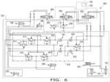
- the hydraulic system 600 may generally include the lift actuators 134, the field swing actuator 146, the transport swing actuator 148, the transport actuator 220, and directional control valves 602, 604, 606 respectively fluidly connected the lift actuators 134, field and transport swing actuators 146, 148, and the transport actuator 220.
- the directional control valves 602, 604, 606 may include a lift valve 602 fluidly connected to the lift actuators 134, a transport valve 604 fluidly connected to the transport actuator 220 and the transport swing actuator 148, and a swing valve 606 fluidly connected to the field swing actuator 146.
- the lift, transport, and swing valves 602, 604, 606 may be operably connected to the controller 150. Thereby, the controller 150 may selectively activate the lift, transport, and swing valves 602, 604, 606 to position the mowing device 120 in between its field and transport positions.
- the hydraulic system 600 may include a lift function, a swing function, a transport deployment function, and a transport stowage function for controlling the operation of the lift actuators 134, the field swing actuator 146, the transport swing actuator 148, and the transport actuator 220.
- the hydraulic system 600 may also include a hydraulic manifold 610 with multiple hydraulic fluid lines, sequence valves 611, 612, 613, 614, 615, 616 and pilot operated check valves 620, 621, 622, 623.
- the hydraulic manifold 610 is fluidly connected in between the actuators 134, 146, 148, 220 and their corresponding valves 602, 604, 606.
- the hydraulic system 600 may or may not include a windrow shield actuator 630, for folding the windrow shields in the transport position, and a tilt actuator 632 for tilting the mowing device 120.
- the hydraulic system 600 may include a relief valve 634, hydraulic pump 636, and multiple shuttle valves (unnumbered).
- the hydraulic system 600 may be incorporated as part of the agricultural vehicle 110 and/or the mowing device 120.
- the directional valves 602, 604, 606, hydraulic pump 636, and relief valve 634 may be positioned on the agricultural vehicle 110 and the hydraulic manifold 610 and actuators 134, 146, 148, 220 may be located on the mowing device 120.
- the hydraulic manifold 610 may be automatically and/or manually controlled.
- the hydraulic system 600 may include one or more hand-controlled inputs, e.g. levers, switches, etc., which the operator can manually operate to activate any desired component of the hydraulic system 600, such as the directional valves 602, 604, 606.
- the hydraulic system 600 has a built-in lockout feature wherein the transport hydraulics, e.g. the transport actuators 220, 148 and fluid lines thereof, are prevented from operating unless the field swing cylinder 146 is fully retracted in the full field right position of the mowing device 120 and the lift actuators 134 are fully extended in the fully elevated position of the mowing device 120.
- the check valves 620, 621, 622, 623 render the transport actuators 220, 148 non-functional at any time when the lift actuators 134 are not fully extended and the field swing actuator 146 is not fully retracted.
- this lockout feature prevents the use of the transport system 200 during field operation, such as when mowing, or during roadway transport.
- the hydraulic system 600 also ensures that the trail frame 124 cannot rotate in the wrong direction during the final stage of deploying the transport system 200, which may cause damage to the trail frame 124 and/or transport system 200.
- the lockout feature ensures that the trail frame 124 is located in its full field right position, as opposed to the field left or intermediate position, such that when the transport frame 202 is rotated downwardly it does not contact the trail frame 124, and once the transport frame 202 is fully deployed, the trail frame 124 is prevented from rotating in the wrong direction which would cause the trail frame 124 to contact the transport frame 202.
- the controller 150 will shift the lift valve 602 so that the lift actuators 134 start raising the trail frame 124. The extension of the actuators 134 will then trip the sequence valve 616 and opens the check valves 620, 622. It is noted that if the mowing device 120 includes a tilt actuator 632, then the tilt cylinder will also retract upon raising the mowing device 120.
- the controller 150 will shift the swing valve 606 to retract and/or extend the field swing actuator 146. This will then trip the sequence valve 611 and open the check valves 621, 623. It is noted that the sequence valve 611 will remain closed if the field swing actuator 146 fully extends.
- the controller 150 will fully extend the lift actuators 134, and lock the lift valve 602 therewith, and fully retract the field swing actuator 146, and lock the swing valve 606 therewith. Thereafter, the controller 150 will shift the transport valve 604 to extend the transport swing actuator 148. In so doing, the controller 150 will also lock the transport valve 604 in this position throughout deployment of the transport frame 202 so that a hydraulic fluid flow is provided through the check valves 620, 621 in order to extend the transport actuator 220.
- the lift, transport, and swing valves 602, 604, 606 will remain locked for transport, the transport swing actuator 148 has been completely extended, and now the sequence valve 612 will trip and allow hydraulic fluid flow to the windrow shield actuator 630, if equipped. If the mowing device 120 is not equipped with such a windrow shield actuator 630, then this stage of the sequence may be omitted.
- the swing valve 606, and transport valve 604 will remain locked for transport, the windrow shield actuator 630 will be fully extended, and now sequence valve 613 will trip and allow hydraulic fluid flow to the transport actuator 220.
- the controller 150 will shift the transport valve 604 to the blocked position and will shift the swing valve 606 to fully extend the field swing actuator 146 in order to place the trail frame 124 in its full lateral transport position, wherein the trail frame 124 is substantially parallel to the tongue 122.
- the controller 150 will shift the lift valve 602 to its lower position, and thereby the lift actuators 134 will retract and lift the field wheels 126, 128 upwardly to increase ground clearance.
- the check valves 620, 621, 622, 623 will be closed, which disables transport hydraulic function during transport of the mowing device 120.
- the controller 150 will shift the lift valve 602 to extend the lift actuators 134, tripping the sequence valve 616 and opening the check valves 620, 622.
- the controller 150 will also shift the swing valve 606 to retract and pressurize the field swing actuator 146, tripping sequence valve 611 and opening the check valves 621, 623.
- the controller 150 will shift the transport valve 604 to provide hydraulic fluid flow through the check valves 622, 623.
- the transport actuator 220 will retract.
- the transport valve 604 will remain locked in this position through stowage of the transport system 200.
- the lift valve 602 and the swing valve 606 will remain locked, to keep the check valves 620, 622, 621, 623 open, and the transport valve 604 will remain locked.
- the sequence valve 614 will trip, which allows hydraulic fluid flow to retract the windrow shield actuator 630, if equipped.
- the lift valve 602 and the swing valve 606 will remain locked, to keep the check valves 620, 622, 621, 623 open, and the transport valve 604 will remain locked.
- the sequence valve 615 will trip, which allows hydraulic fluid flow through to retract the transport swing actuator 148.
- the transport swing cylinder 148 has been completely retracted and the transport valve 604 shifts into its closed position by the controller 150.
- the controller 150 will also shift the lift valve 602 and the swing valve 606 to their respective closed position, thereby closing the check valves 620, 621, 622, 623 and locking out the transport hydraulics from operation.
- the mowing device 120 may be in its full field right position.
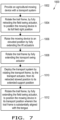
- the method 1000 initially includes the step of providing the mowing device 120 with the transport system 200 as described above (at block 1002).
- the transport hydraulics of the transport system 200 may be prevented from operation until the mowing device 120 is positioned in its full field right or left position and then in its fully lifted position.
- the method 1000 may include the initial steps of locking the transport actuator 220, by the check valves 620, 621, 622, 623, when the mowing device 120 is being moved in its field and/or transport positions, and unlocking the transport actuator 220, by the plurality of check valves 620, 621, 622, 623, by fully retracting the field swing actuator 146 and fully extending the lift actuators 134. Therefore, in order to engage the transport system 200, the mowing device 120 may be initially positioned in its full field right or left position by the field swing actuator 146 (at step 1004). For example, the mowing device 120 may be positioned in its full field right position by fully retracting the field swing actuator 146.
- the mowing device 120 may be raised, by the lift actuators 134, in order to lift or raise the mowing device 120 in a fully elevated position (at block 1006).
- This fully elevated position provides additional ground clearance that enables the deployment of the transport system 200.
- the method step 1006 may occur first before the method step 1004.
- the transport hydraulics of the transport system 200 may be unlocked for allowing the operation thereof.
- the trail frame 124 may be rotated once again by fully extending the transport swing actuator 148 (at block 1008).
- the trail frame 124 may be substantially perpendicular to the tongue 122, plus or minus 30 degrees, even though the field swing cylinder 146 has remained fully retracted. Then, to position the mowing device 120 in the transport position, the transport frame 202 may be fully deployed and the trail frame 124 may be rotated to accordingly reduce the overall width of the mowing device 120.
- the transport system 200 may be deployed by rotating the transport frame 202, by the transport actuator 220, from its retracted stowed position into its extended support position (at block 1010; FIG. 4 ). Thereby, the transport wheels 204, 206 are moved toward the ground, and the transport wheels 204, 206 accordingly lift the trail-frame wheels 126, 128 off the ground.
- the trail frame 124 When the transport wheels 204, 206 are fully deployed, the trail frame 124 may be rotated, by fully extending the field swing actuator 146, so that the trail frame 124 is substantially aligned with the tongue 122, for example substantially parallel to the tongue 122, plus or minus 30 degrees (at block 1012; FIG. 5 ). In this laterally aligned position of the trail frame 124, both of the field and transport cylinders 146, 148 may be fully extended. Thereafter, the mowing device 120, which now has a smaller overall width, may be towed by the agricultural vehicle 110. As can be appreciated, the mowing device 120 may be positioned in the field position by performing the method steps 1012, 1010, 1008, 1006 of the method 1000 in reverse order.
- the transport frame 202 may be rotated from its extended support position into its retracted position, the trail frame 124 may be rotated to be substantially perpendicular to tongue 122, plus or minus 30 degrees, for increasing the overall width of the mowing device 120, and the mowing device 120 may be lowered by the lift actuators 134.
- the operator may stay within the cab of the agricultural vehicle 110 while the method 1000 is conducted by the controller 150.
- the method 1000 may be conducted manually by the operator, wherein the operator activates the directional valves 602, 604, 606 by hand.
- the steps of the method 1000 are performed by the controller 150 upon loading and executing software code or instructions which are tangibly stored on a tangible computer readable medium, such as on a magnetic medium, e.g., a computer hard drive, an optical medium, e.g., an optical disc, solid-state memory, e.g., flash memory, or other storage media known in the art.
- a tangible computer readable medium such as on a magnetic medium, e.g., a computer hard drive, an optical medium, e.g., an optical disc, solid-state memory, e.g., flash memory, or other storage media known in the art.
- any of the functionality performed by the controller 150 described herein, such as the method 1000 is implemented in software code or instructions which are tangibly stored on a tangible computer readable medium.
- the controller 150 loads the software code or instructions via a direct interface with the computer readable medium or via a wired and/or wireless network. Upon loading and executing such software code or instructions by the controller 150, the controller 150
- software code or “code” used herein refers to any instructions or set of instructions that influence the operation of a computer or controller. They may exist in a computer-executable form, such as machine code, which is the set of instructions and data directly executed by a computer's central processing unit or by a controller, a human-understandable form, such as source code, which may be compiled in order to be executed by a computer's central processing unit or by a controller, or an intermediate form, such as object code, which is produced by a compiler.
- the term "software code” or “code” also includes any human-understandable computer instructions or set of instructions, e.g., a script, that may be executed on the fly with the aid of an interpreter executed by a computer's central processing unit or by a controller.
Landscapes
- Life Sciences & Earth Sciences (AREA)
- Environmental Sciences (AREA)
- Engineering & Computer Science (AREA)
- Mechanical Engineering (AREA)
- Soil Sciences (AREA)
- Harvester Elements (AREA)
- Zoology (AREA)
Claims (9)
- Un dispositif de fauchage agricole (120) configuré pour être tracté par un véhicule agricole (110), le dispositif de fauchage agricole (120) pouvant être configuré dans une position de champ pour couper un matériau récolté dans un champ et une position de transport pour transporter le dispositif de fauchage agricole (120), le dispositif de fauchage agricole (120) comprenant :une languette (122) configurée pour le raccordement au véhicule agricole (110) ;un châssis de remorquage (124) raccordé de manière rotative à la languette (122) ;une barre de coupe (130) raccordée au châssis de remorquage (124) et configurée pour couper le matériau récolté dans la position de champ ;une première roue (126) de châssis de remorquage et une seconde roue (128) de châssis de remorquage, chacune étant raccordée de manière rotative au châssis de remorquage (124) et configurée pour soutenir le châssis de remorquage (124) en position de champ ;un premier vérin de levage (134) raccordé de manière fonctionnelle entre le châssis de remorquage (124) et la première roue (126) de châssis de remorquage et un second vérin de levage (134) raccordé de manière fonctionnelle entre le châssis de remorquage (124) et la seconde roue (128) de châssis de remorquage, le premier vérin de levage (134) et le second vérin de levage (134) étant configurés pour lever le châssis de remorquage (124) ;un mécanisme d'actionnement du châssis de remorquage (136) raccordé de manière fonctionnelle entre la languette (122) et le châssis de remorquage (124) et configuré pour faire pivoter le châssis de remorquage (124) ; etun système de transport (200) comprenant :un châssis de transport (202) ;une première roue de transport (204) et une seconde roue de transport (206), chacune étant raccordée de manière rotative au châssis de transport (202) et configurée pour soutenir la languette (122) en position de transport ;caractérisé en ce queun mécanisme d'actionnement de transport (208) raccordant de manière rotative le châssis de transport (202) à la languette (122), et le mécanisme d'actionnement de transport (208) comprenant un ensemble tringlerie (210) raccordé de manière rotative à un côté de la languette (122), entre le châssis de transport (202) et la languette (122), et un actionneur de transport (220) raccordé de manière fonctionnelle entre la languette (122) et le châssis de transport (202) et configuré pour faire pivoter le châssis de transport (202).
- Le dispositif de fauchage agricole (120) selon la revendication 1, dans lequel le mécanisme d'actionnement du châssis de remorquage (136) comprend un maillon rotatif (144) raccordé de manière rotative à la languette (122) et s'étendant vers l'extérieur de la languette (122), un premier actionneur de châssis de remorquage (146) raccordé au châssis de remorquage (124) et au maillon rotatif (144), et un second actionneur de châssis de remorquage (148) raccordé à la languette (122) et au maillon rotatif (144).
- Le dispositif de fauchage agricole (120) selon la revendication 2, dans lequel le premier actionneur de châssis de remorquage (146) se présente sous la forme d'un actionneur à bascule en position de champ (146) configuré pour pivoter le châssis de remorquage (124) dans la position de champ et le second actionneur de châssis de remorquage (148) se présente sous la forme d'un actionneur à bascule en position de transport (148) configuré pour pivoter le châssis de remorquage (124) de manière à ce qu'il soit sensiblement parallèle à la languette (122) dans la position de transport.
- Le dispositif de fauchage agricole (120) selon la revendication 2 comprend en outre un système hydraulique (600) comprenant le premier vérin de levage (134), le second vérin de levage (134), le premier actionneur de châssis de remorquage (146), le second actionneur de châssis de remorquage (148), l'actionneur de transport (220), une vanne de levage (602) raccordée fluidiquement au premier vérin de levage (134) et au second vérin de levage (134), une vanne de transport (604) raccordée fluidiquement à l'actionneur de transport (220) et au second actionneur de châssis de remorquage (148), et une vanne oscillante (606) raccordée fluidiquement au premier actionneur de châssis de remorquage (146).
- Le dispositif de fauchage agricole (120) selon la revendication 4, dans lequel le système hydraulique (600) comprend en outre un collecteur hydraulique (610) raccordé fluidiquement entre la vanne de levage (602), la vanne de transport (604) et la vanne oscillante (606) et le premier vérin de levage (134), le second vérin de levage (134), l'actionneur de transport (220), le premier actionneur de châssis de remorquage (146) et le second actionneur de châssis de remorquage (148).
- Le dispositif de fauchage agricole (120) selon la revendication 5, dans lequel le collecteur hydraulique (610) comprend une pluralité de vannes de séquence (611, 612, 613, 614, 615, 616) et une pluralité de clapets anti-retour (620, 621, 622, 623).
- Le dispositif de fauchage agricole (120) selon la revendication 6, dans lequel le système hydraulique (600) comporte un dispositif de verrouillage intégré de sorte que le fonctionnement de l'actionneur de transport (220) est empêché par la pluralité de clapets anti-retour (620, 621, 622, 623) à moins que le premier actionneur de châssis de remorquage (146) soit en position rétractée complète et que le premier et le second vérin de levage (134) soient en position étendue complète.
- Le dispositif de fauchage agricole (120) selon la revendication 1, dans lequel l'actionneur de transport (220) est raccordé entre la languette (122) et l'ensemble tringlerie (210).
- Le dispositif de fauchage agricole (120) selon l'une quelconque des revendications précédentes, dans lequel le châssis de transport (202) est configuré pour être en position rétractée et rangée en position de champ dans laquelle le châssis de transport (202) est situé au-dessus du châssis de remorquage (124) et étendue dans la position de transport dans laquelle la première roue de transport (204) et la seconde roue de transport (206) soutiennent la languette (122).
Applications Claiming Priority (1)
| Application Number | Priority Date | Filing Date | Title |
|---|---|---|---|
| US16/831,034 US11690316B2 (en) | 2020-03-26 | 2020-03-26 | Deployment mechanism and hydraulic system for an agricultural mower |
Publications (2)
| Publication Number | Publication Date |
|---|---|
| EP3884751A1 EP3884751A1 (fr) | 2021-09-29 |
| EP3884751B1 true EP3884751B1 (fr) | 2025-04-09 |
Family
ID=75223081
Family Applications (1)
| Application Number | Title | Priority Date | Filing Date |
|---|---|---|---|
| EP21164719.3A Active EP3884751B1 (fr) | 2020-03-26 | 2021-03-24 | Mécanisme de déploiement et système hydraulique pour tondeuse agricole |
Country Status (2)
| Country | Link |
|---|---|
| US (1) | US11690316B2 (fr) |
| EP (1) | EP3884751B1 (fr) |
Families Citing this family (5)
| Publication number | Priority date | Publication date | Assignee | Title |
|---|---|---|---|---|
| US11497168B2 (en) * | 2020-03-26 | 2022-11-15 | Cnh Industrial America Llc | Lateral transport system for an agricultural mower with non-parallel axes of transport deployment and wheel rotation |
| US12035646B2 (en) * | 2020-12-11 | 2024-07-16 | Deere & Company | Integrated transport coupling system |
| PL246811B1 (pl) * | 2022-05-31 | 2025-03-10 | Adam Simkowski | Urządzenie koszące |
| US20240397872A1 (en) * | 2023-05-31 | 2024-12-05 | Cnh Industrial America Llc | Automated header retaining system for lateral transport center-pivot mower |
| US20250255208A1 (en) * | 2024-02-09 | 2025-08-14 | Great Plains Manufacturing, Inc. | Endwise transportable implement with sequential hydraulic circuit |
Family Cites Families (15)
| Publication number | Priority date | Publication date | Assignee | Title |
|---|---|---|---|---|
| US3791673A (en) | 1972-11-08 | 1974-02-12 | American Prod Inc | Folding means for implement frame structures |
| FR2567710B1 (fr) * | 1984-07-19 | 1987-05-07 | Kuhn Sa | Procede de transformation d'une machine de recolte pour l'amener d'une position de travail dans une position de transport, et machine de recolte utilisant ce procede |
| US4927165A (en) | 1989-02-27 | 1990-05-22 | Deutz-Allis Corporation | Master/slave hydraulic system for adjusting the support wheels of an articulated implement |
| HU203440B (en) * | 1989-04-07 | 1991-08-28 | Szolnoki Mezoegazdasagi Gepgya | Collapsible trailed underframe for plough-land implements particularly rotary scythes |
| FR2660518B1 (fr) * | 1990-04-05 | 1993-06-11 | Kuhn Sa | Machine agricole avec dispositif de detection de la position intermediaire du moyen de liaison. |
| DK144793D0 (da) * | 1993-06-09 | 1993-12-23 | Jf Fabriken J Freudendahl | Slaamaskine |
| US5806291A (en) * | 1995-06-26 | 1998-09-15 | New Holland North America, Inc. | Transport latch for pull-type harvesters |
| DE10029363A1 (de) * | 2000-06-15 | 2001-12-20 | Deere & Co | Gezogenes landwirtschaftliches Gerät |
| FR2840152B1 (fr) | 2002-05-29 | 2005-03-04 | Kuhn Sa | Machine agricole comportant un dispositif de mise en transport |
| US8112977B2 (en) * | 2010-02-18 | 2012-02-14 | Cnh America Llc | Disc mower narrow transport frame |
| CA2815427C (fr) * | 2012-04-26 | 2016-06-28 | Macdon Industries Ltd. | Systeme de transport de machine a recolter par traction pourvu d'une plaque de protection d'andains etales |
| US9622404B2 (en) * | 2013-09-11 | 2017-04-18 | Cnh Industrial America Llc | Integral lateral transport of a mower |
| US9596808B2 (en) * | 2014-04-30 | 2017-03-21 | Cnh Industrial America Llc | Transport system for a center pivot agricultural machine |
| US9565800B2 (en) * | 2014-09-08 | 2017-02-14 | Cnh Industrial America Llc | Windrow shield control system for a header of an agricultural harvester |
| US10631452B2 (en) * | 2018-01-02 | 2020-04-28 | Cnh Industrial America Llc | Lateral transport system for harvester |
-
2020
- 2020-03-26 US US16/831,034 patent/US11690316B2/en active Active
-
2021
- 2021-03-24 EP EP21164719.3A patent/EP3884751B1/fr active Active
Also Published As
| Publication number | Publication date |
|---|---|
| US20210298219A1 (en) | 2021-09-30 |
| US11690316B2 (en) | 2023-07-04 |
| EP3884751A1 (fr) | 2021-09-29 |
Similar Documents
| Publication | Publication Date | Title |
|---|---|---|
| EP3884751B1 (fr) | Mécanisme de déploiement et système hydraulique pour tondeuse agricole | |
| EP3884764B1 (fr) | Système de transport latéral pour tondeuse agricole | |
| CA1105517A (fr) | Verrouillage hydraulique sur attelage pivotable de machine tractee | |
| EP3504950B1 (fr) | Système de transport latéral pour une moissonneuse et procédé l'utilisant | |
| CA2306310C (fr) | Recolteuse a roues munie d'un outil de recolte | |
| EP3061333B1 (fr) | Système de transport pour une machine de récolte de cultures à traction | |
| US9622404B2 (en) | Integral lateral transport of a mower | |
| US10143138B2 (en) | Transport system for a center pivot agricultural machine | |
| US9603306B2 (en) | Agricultural machine with retaining elements for retaining a header in an elevated position | |
| US8112977B2 (en) | Disc mower narrow transport frame | |
| EP3884765B1 (fr) | Système de transport latéral pour tondeuse agricole avec axes non parallèles de déploiement de transport et de rotation de roue | |
| US20250000007A1 (en) | Concurrent field and transport cylinder actuation for mowing device transport | |
| US20250057065A1 (en) | Mower folding flail curtain | |
| US20250212715A1 (en) | Transport hydraulic pressure used to block retraction of header tilt cylinder | |
| US20250127071A1 (en) | Mowing assembly transport mechanical interlock | |
| US20240397872A1 (en) | Automated header retaining system for lateral transport center-pivot mower |
Legal Events
| Date | Code | Title | Description |
|---|---|---|---|
| PUAI | Public reference made under article 153(3) epc to a published international application that has entered the european phase |
Free format text: ORIGINAL CODE: 0009012 |
|
| STAA | Information on the status of an ep patent application or granted ep patent |
Free format text: STATUS: THE APPLICATION HAS BEEN PUBLISHED |
|
| AK | Designated contracting states |
Kind code of ref document: A1 Designated state(s): AL AT BE BG CH CY CZ DE DK EE ES FI FR GB GR HR HU IE IS IT LI LT LU LV MC MK MT NL NO PL PT RO RS SE SI SK SM TR |
|
| STAA | Information on the status of an ep patent application or granted ep patent |
Free format text: STATUS: REQUEST FOR EXAMINATION WAS MADE |
|
| 17P | Request for examination filed |
Effective date: 20220329 |
|
| RBV | Designated contracting states (corrected) |
Designated state(s): AL AT BE BG CH CY CZ DE DK EE ES FI FR GB GR HR HU IE IS IT LI LT LU LV MC MK MT NL NO PL PT RO RS SE SI SK SM TR |
|
| STAA | Information on the status of an ep patent application or granted ep patent |
Free format text: STATUS: EXAMINATION IS IN PROGRESS |
|
| 17Q | First examination report despatched |
Effective date: 20230323 |
|
| GRAP | Despatch of communication of intention to grant a patent |
Free format text: ORIGINAL CODE: EPIDOSNIGR1 |
|
| STAA | Information on the status of an ep patent application or granted ep patent |
Free format text: STATUS: GRANT OF PATENT IS INTENDED |
|
| INTG | Intention to grant announced |
Effective date: 20241029 |
|
| GRAS | Grant fee paid |
Free format text: ORIGINAL CODE: EPIDOSNIGR3 |
|
| GRAA | (expected) grant |
Free format text: ORIGINAL CODE: 0009210 |
|
| STAA | Information on the status of an ep patent application or granted ep patent |
Free format text: STATUS: THE PATENT HAS BEEN GRANTED |
|
| AK | Designated contracting states |
Kind code of ref document: B1 Designated state(s): AL AT BE BG CH CY CZ DE DK EE ES FI FR GB GR HR HU IE IS IT LI LT LU LV MC MK MT NL NO PL PT RO RS SE SI SK SM TR |
|
| REG | Reference to a national code |
Ref country code: GB Ref legal event code: FG4D |
|
| REG | Reference to a national code |
Ref country code: CH Ref legal event code: EP |
|
| REG | Reference to a national code |
Ref country code: DE Ref legal event code: R096 Ref document number: 602021028755 Country of ref document: DE |
|
| REG | Reference to a national code |
Ref country code: IE Ref legal event code: FG4D |
|
| REG | Reference to a national code |
Ref country code: NL Ref legal event code: MP Effective date: 20250409 |
|
| PG25 | Lapsed in a contracting state [announced via postgrant information from national office to epo] |
Ref country code: NL Free format text: LAPSE BECAUSE OF FAILURE TO SUBMIT A TRANSLATION OF THE DESCRIPTION OR TO PAY THE FEE WITHIN THE PRESCRIBED TIME-LIMIT Effective date: 20250409 |
|
| REG | Reference to a national code |
Ref country code: AT Ref legal event code: MK05 Ref document number: 1782631 Country of ref document: AT Kind code of ref document: T Effective date: 20250409 |
|
| PG25 | Lapsed in a contracting state [announced via postgrant information from national office to epo] |
Ref country code: ES Free format text: LAPSE BECAUSE OF FAILURE TO SUBMIT A TRANSLATION OF THE DESCRIPTION OR TO PAY THE FEE WITHIN THE PRESCRIBED TIME-LIMIT Effective date: 20250409 Ref country code: PT Free format text: LAPSE BECAUSE OF FAILURE TO SUBMIT A TRANSLATION OF THE DESCRIPTION OR TO PAY THE FEE WITHIN THE PRESCRIBED TIME-LIMIT Effective date: 20250811 Ref country code: FI Free format text: LAPSE BECAUSE OF FAILURE TO SUBMIT A TRANSLATION OF THE DESCRIPTION OR TO PAY THE FEE WITHIN THE PRESCRIBED TIME-LIMIT Effective date: 20250409 |
|
| REG | Reference to a national code |
Ref country code: LT Ref legal event code: MG9D |
|
| PG25 | Lapsed in a contracting state [announced via postgrant information from national office to epo] |
Ref country code: GR Free format text: LAPSE BECAUSE OF FAILURE TO SUBMIT A TRANSLATION OF THE DESCRIPTION OR TO PAY THE FEE WITHIN THE PRESCRIBED TIME-LIMIT Effective date: 20250710 Ref country code: NO Free format text: LAPSE BECAUSE OF FAILURE TO SUBMIT A TRANSLATION OF THE DESCRIPTION OR TO PAY THE FEE WITHIN THE PRESCRIBED TIME-LIMIT Effective date: 20250709 |
|
| PG25 | Lapsed in a contracting state [announced via postgrant information from national office to epo] |
Ref country code: PL Free format text: LAPSE BECAUSE OF FAILURE TO SUBMIT A TRANSLATION OF THE DESCRIPTION OR TO PAY THE FEE WITHIN THE PRESCRIBED TIME-LIMIT Effective date: 20250409 |
|
| PG25 | Lapsed in a contracting state [announced via postgrant information from national office to epo] |
Ref country code: BG Free format text: LAPSE BECAUSE OF FAILURE TO SUBMIT A TRANSLATION OF THE DESCRIPTION OR TO PAY THE FEE WITHIN THE PRESCRIBED TIME-LIMIT Effective date: 20250409 |
|
| PG25 | Lapsed in a contracting state [announced via postgrant information from national office to epo] |
Ref country code: HR Free format text: LAPSE BECAUSE OF FAILURE TO SUBMIT A TRANSLATION OF THE DESCRIPTION OR TO PAY THE FEE WITHIN THE PRESCRIBED TIME-LIMIT Effective date: 20250409 |
|
| PG25 | Lapsed in a contracting state [announced via postgrant information from national office to epo] |
Ref country code: AT Free format text: LAPSE BECAUSE OF FAILURE TO SUBMIT A TRANSLATION OF THE DESCRIPTION OR TO PAY THE FEE WITHIN THE PRESCRIBED TIME-LIMIT Effective date: 20250409 |
|
| PG25 | Lapsed in a contracting state [announced via postgrant information from national office to epo] |
Ref country code: RS Free format text: LAPSE BECAUSE OF FAILURE TO SUBMIT A TRANSLATION OF THE DESCRIPTION OR TO PAY THE FEE WITHIN THE PRESCRIBED TIME-LIMIT Effective date: 20250709 |
|
| PG25 | Lapsed in a contracting state [announced via postgrant information from national office to epo] |
Ref country code: IS Free format text: LAPSE BECAUSE OF FAILURE TO SUBMIT A TRANSLATION OF THE DESCRIPTION OR TO PAY THE FEE WITHIN THE PRESCRIBED TIME-LIMIT Effective date: 20250809 |
|
| PG25 | Lapsed in a contracting state [announced via postgrant information from national office to epo] |
Ref country code: LV Free format text: LAPSE BECAUSE OF FAILURE TO SUBMIT A TRANSLATION OF THE DESCRIPTION OR TO PAY THE FEE WITHIN THE PRESCRIBED TIME-LIMIT Effective date: 20250409 |
|
| REG | Reference to a national code |
Ref country code: DE Ref legal event code: R097 Ref document number: 602021028755 Country of ref document: DE |
|
| PG25 | Lapsed in a contracting state [announced via postgrant information from national office to epo] |
Ref country code: DK Free format text: LAPSE BECAUSE OF FAILURE TO SUBMIT A TRANSLATION OF THE DESCRIPTION OR TO PAY THE FEE WITHIN THE PRESCRIBED TIME-LIMIT Effective date: 20250409 Ref country code: SM Free format text: LAPSE BECAUSE OF FAILURE TO SUBMIT A TRANSLATION OF THE DESCRIPTION OR TO PAY THE FEE WITHIN THE PRESCRIBED TIME-LIMIT Effective date: 20250409 |
|
| PG25 | Lapsed in a contracting state [announced via postgrant information from national office to epo] |
Ref country code: CZ Free format text: LAPSE BECAUSE OF FAILURE TO SUBMIT A TRANSLATION OF THE DESCRIPTION OR TO PAY THE FEE WITHIN THE PRESCRIBED TIME-LIMIT Effective date: 20250409 |
|
| PG25 | Lapsed in a contracting state [announced via postgrant information from national office to epo] |
Ref country code: EE Free format text: LAPSE BECAUSE OF FAILURE TO SUBMIT A TRANSLATION OF THE DESCRIPTION OR TO PAY THE FEE WITHIN THE PRESCRIBED TIME-LIMIT Effective date: 20250409 |
|
| PG25 | Lapsed in a contracting state [announced via postgrant information from national office to epo] |
Ref country code: RO Free format text: LAPSE BECAUSE OF FAILURE TO SUBMIT A TRANSLATION OF THE DESCRIPTION OR TO PAY THE FEE WITHIN THE PRESCRIBED TIME-LIMIT Effective date: 20250409 Ref country code: SK Free format text: LAPSE BECAUSE OF FAILURE TO SUBMIT A TRANSLATION OF THE DESCRIPTION OR TO PAY THE FEE WITHIN THE PRESCRIBED TIME-LIMIT Effective date: 20250409 |
|
| PLBE | No opposition filed within time limit |
Free format text: ORIGINAL CODE: 0009261 |
|
| STAA | Information on the status of an ep patent application or granted ep patent |
Free format text: STATUS: NO OPPOSITION FILED WITHIN TIME LIMIT |
|
| REG | Reference to a national code |
Ref country code: CH Ref legal event code: L10 Free format text: ST27 STATUS EVENT CODE: U-0-0-L10-L00 (AS PROVIDED BY THE NATIONAL OFFICE) Effective date: 20260218 |
|
| 26N | No opposition filed |
Effective date: 20260112 |
|
| PGFP | Annual fee paid to national office [announced via postgrant information from national office to epo] |
Ref country code: GB Payment date: 20260319 Year of fee payment: 6 |
|
| PGFP | Annual fee paid to national office [announced via postgrant information from national office to epo] |
Ref country code: IE Payment date: 20260318 Year of fee payment: 6 |
|
| PGFP | Annual fee paid to national office [announced via postgrant information from national office to epo] |
Ref country code: IT Payment date: 20260320 Year of fee payment: 6 |
|
| PGFP | Annual fee paid to national office [announced via postgrant information from national office to epo] |
Ref country code: FR Payment date: 20260323 Year of fee payment: 6 |