EP3885067B9 - Outil de coupe et unité de coupe comprenant ledit outil de coupe - Google Patents
Outil de coupe et unité de coupe comprenant ledit outil de coupe Download PDFInfo
- Publication number
- EP3885067B9 EP3885067B9 EP21163672.5A EP21163672A EP3885067B9 EP 3885067 B9 EP3885067 B9 EP 3885067B9 EP 21163672 A EP21163672 A EP 21163672A EP 3885067 B9 EP3885067 B9 EP 3885067B9
- Authority
- EP
- European Patent Office
- Prior art keywords
- lateral surface
- tool
- tool holder
- support body
- respect
- Prior art date
- Legal status (The legal status is an assumption and is not a legal conclusion. Google has not performed a legal analysis and makes no representation as to the accuracy of the status listed.)
- Active
Links
Images




Classifications
-
- B—PERFORMING OPERATIONS; TRANSPORTING
- B23—MACHINE TOOLS; METAL-WORKING NOT OTHERWISE PROVIDED FOR
- B23B—TURNING; BORING
- B23B29/00—Holders for non-rotary cutting tools; Boring bars or boring heads; Accessories for tool holders
- B23B29/04—Tool holders for a single cutting tool
- B23B29/046—Tool holders for a single cutting tool with an intermediary toolholder
-
- B—PERFORMING OPERATIONS; TRANSPORTING
- B23—MACHINE TOOLS; METAL-WORKING NOT OTHERWISE PROVIDED FOR
- B23B—TURNING; BORING
- B23B2250/00—Compensating adverse effects during turning, boring or drilling
- B23B2250/12—Cooling and lubrication
-
- B—PERFORMING OPERATIONS; TRANSPORTING
- B23—MACHINE TOOLS; METAL-WORKING NOT OTHERWISE PROVIDED FOR
- B23B—TURNING; BORING
- B23B2270/00—Details of turning, boring or drilling machines, processes or tools not otherwise provided for
- B23B2270/06—Use of elastic deformation
Definitions
- the present invention refers to the field of subtractive manufacturing. More specifically, the present invention refers to a tool for removal machining and a related tool-holder cutting unit for machine tools.
- each such tool - also referred to as cartridges in the jargon - comprises a support body, a cutting element - also referred to as an insert in the jargon -, fastening elements - for example, screws and brackets - and any ancillary elements - for example, gaskets, underplates, etc..
- a tool holder is provided for attaching the tool to the machine tool, which is attached to the machine tool and the tool, in order to ensure the correct positioning of the required tool and enable the desired machining of a workpiece.
- the coupling between the tool and the tool holder is a critical aspect, as on the one hand it must be stable and reliable to ensure precise machining of workpieces, and on the other hand the assembly and disassembly of tools from the tool holder must be simple and quick to ensure effective replacement of tools or components thereof.
- the Applicant presented a tool and tool holder pair provided with matching surfaces having complementary abutting elements.
- Such abutting elements allow the tool to be simply and accurately coupled to the tool holder and, in addition, allow a single screw to be used to obtain a stable and reliable attachment of the tool to the tool holder.
- the tool is capable of withstanding mechanical stress for extended periods, remaining stable while machining a workpiece, and still allows for quick and easy replacement of the tool as needed.
- the present invention is directed to a cutting tool, for example a turning, blanking, milling, and/or threading tool.
- the tool includes a cutting element configured to contact a body to be machined, and a support body configured to support the cutting element in a working position and to be coupled to a tool holder mounted on a processing machine.
- the support body includes a first side surface configured to be coupled to a first surface of the tool holder, the first side surface comprising at least one abutting surface configured to be coupled to a complementary abutting surface of the first surface of the tool holder, and at least one fastening element configured to be coupled to a complementary fastening element included in the first surface of the tool holder to secure the tool to the tool holder.
- the support body includes a second lateral surface configured to abut at least partially against a second surface of the tool holder.
- the second lateral surface is adjacent to the first lateral surface, and includes at least one portion inclined relative thereto.
- the second side surface includes an abutting portion configured to abut against the second surface of the tool holder.
- the second lateral surface delimits an elastic element of the support body.
- the elastic element is configured to generate a resilient elastic force substantially orthogonal to the abutting portion when the abutting portion is abutting against the second surface of the tool holder.
- the second lateral surface allows the forces associated with machining vibrations to be unloaded onto the tool holder, thereby conferring greater stability to the tool and substantially reducing the stresses on the one or more fastening elements used to couple the tool to the tool holder.
- both an increase in tool life and improved machining accuracy of workpieces by the machine tool are achieved.
- This structure also ensures optimal coupling between the second lateral surface of the tool body and the tool holder.
- the elasticity of the elastic element allows to compensate for machining tolerances that would limit the uniformity of the coupling of the second lateral surface of the tool body with a corresponding surface of the tool holder.
- the elastic element may be sized to exert a further cushioning function with respect to mechanical stresses to which the tool is subjected during operation of the machine tool.
- the abutting portion is consecutive to the inclined portion.
- the first lateral surface comprises two or more positioning elements configured to correspond to respective two or more complementary positioning elements formed on the first surface of the tool holder.
- at least three of the coupling elements are arranged to delimit a triangular region of the first lateral surface.
- at least part of the surface of the positioning elements defines the abutting surface of the lateral surface.
- the inclined portion of the second lateral surface and the first lateral surface define an angle ⁇ of less than 180°, preferably less than 90°, with respect to a plane orthogonal to both the first lateral surface and the second lateral surface.
- the abutting portion may comprise a dampening element, for example, a deformable element - such as an O-ring - configured to abut against the tool holder.
- a dampening element for example, a deformable element - such as an O-ring - configured to abut against the tool holder.
- the second lateral surface is delimited by a free edge of the support body.
- the elastic element of the support body is further delimited by a slot, referred to as slot, which develops:
- This conformation of the tool body allows the elastic element to be defined and, at same time, allows the tool to be highly robust.
- the elastic element is subjected to a deformation force greater than a limiting value, the walls delimiting the slot come into contact with each other, with the effect of making the elastic element substantially integral with the rest of the tool support body thus ensuring the robustness and stability of the tool.
- the second lateral surface is conformed such that a free end thereof - being distal from the first lateral surface - is at a distance from the first lateral surface of between 0.2 and 0.4 times, preferably between 0.25 and 0.3 times, a length of the first lateral surface, both calculated in the plane orthogonal to both abutting surfaces.
- This ratio allows to obtain a particularly robust and reliable structure.
- the slot has a length along a direction parallel to or inclined with respect to the inclined portion of the second lateral surface of between 0.5 and 1.5, preferably 0.9 times the length of the second lateral surface calculated in the plane orthogonal to both the first lateral surface and the second lateral surface.
- the slot preferably has a distance from the second lateral surface such that a thickness of the elastic element - calculated with respect to the orthogonal plane - is substantially constant or within an acceptable range of values throughout the extension of the slot within the body.
- said range is between 0.2 and 0.4 times the length of the slot, even more preferably between 0.25 and 0.35 times the length of the slot, calculated in the plane orthogonal to both abutting surfaces.
- said elastic element is a protruding appendage of the support body, said protruding appendage, projecting from the support body in a direction orthogonal or inclined to the first support surface, preferably, such that a free end of the appendage - being distal from the first lateral surface of the body - is at a distance from the first lateral surface of between 0.2 and 0.4 times, preferably between 0.25 and 0.3 times, a length of the first lateral surface where both the distance and the length are calculated in a plane orthogonal to both abutting surfaces.
- the appendage has a width of between 0.2 and 0.4 times, preferably between 0.25 and 0.35 times the distance between the free end of the appendage and the first lateral surface of the body calculated in the plane orthogonal to both abutting surfaces.
- the inclined portion of the second lateral surface is proximal to the first lateral surface. Further, the abutting portion is substantially orthogonal to the first lateral surface.
- the second lateral surface includes a connecting portion adjacent to the first lateral surface and the inclined portion of the second lateral surface, said connecting portion being concave.
- the connecting portion defines a circumferential arc profile with respect to a plane orthogonal to the first lateral surface and the second lateral surface.
- This cutting unit allows to obtain the above-mentioned advantages with reference to the cutting tool according to the present invention. Further, a plurality of tools having a support body with the above-mentioned features can be provided, with a cutting element suitable for performing different machining or cutting operations all of which are suitable for being coupled to the same tool holder.
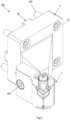
- a tool 1 also referred to as a 'cartridge', in accordance with one embodiment of the present invention.
- the tool 1 includes a support body 10 on which a cutting element 20 is mounted also referred to by the term 'insert' in the jargon.
- the body 10 includes a housing 11 in which the cutting element 20 is inserted, preferably together with a spacer element 30, also referred to as a 'subplate' in the jargon.
- the cutting element 20 and the spacer element 30 are locked in position by a screw (not visible in the Figures) and, even more preferably, by a bracket 40, which is in turn screwed to the body 10 by means of a screw 50.
- the housing is formed at one end of the body 10 and is conformed such that at least one portion of the cutting element 20 projects outwardly.
- the body 10 and the bracket 40 include one or more nozzles (four of which are visible in Figure 1 ) configured to emit a lubrication/cleaning fluid - for example, a jet of water - to the cutting element 20 so as to remove machining swarf and maintain a reduced temperature of the cutting element 20 that would otherwise become frictionally hot during machining.
- a lubrication/cleaning fluid - for example, a jet of water - to the cutting element 20 so as to remove machining swarf and maintain a reduced temperature of the cutting element 20 that would otherwise become frictionally hot during machining.
- the body 10 further includes a through-hole 13 configured to receive a fastening screw 101 - visible in Figure 5 - for attachment to a tool holder - for example, the tool holder 2 illustrated in Figures 5-7 and described below.
- the tool 1 is provided with a first lateral surface 15, which is configured to be associated with a first lateral surface 81 of the tool holder 2 - as visible in Figures 6-9 .
- the first lateral surface 15 is, preferably, exposed on the body in a direction substantially opposite to the direction towards which the cutting element 20 is exposed.
- the body 10 comprises a plurality of positioning elements, three recesses 151 - substantially hemispherical in the example of the Figures -, each of which is suitable for receiving a complementary positioning element 813 of the tool holder 2 as appreciable in Figures 6-9 .
- the recesses 151 are arranged on the first lateral surface 15 so as to delimit a triangular region.
- the three recesses 151 are arranged at the vertices of said triangular region. Even more preferably, the recesses 151 are arranged at 120° to each other with respect to the through-hole 13.
- the body 10 comprised an inlet port 153 exposed on the first lateral surface 15, which is configured to hydraulically match tightly with a corresponding outlet port 815 of the tool holder 2 - as visible in Figure 6 - in order to receive the aforementioned lubrication/cleaning fluid.
- the body 10 also comprises a second lateral surface 17, which is configured to abut at least partially against a corresponding second lateral surface 83 of the tool holder 2 - as appreciable in Figures 6-9 .
- the second lateral surface 17 is adjacent to the first lateral surface 15 and comprises, as it moves away from the first lateral surface 15, a connecting portion 171, an inclined portion 173, and an abutting portion 175.
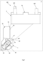
- the connecting portion 171 follows one end of the first lateral surface 15 and the inclined portion 173 of the second lateral surface 17 and defines a circumferential arc profile with respect to a plane ⁇ (illustrated in Figure 3 ) orthogonal to both the first lateral surface 15 and the second lateral surface 17.
- the inclined portion 173 is configured to define an angle ⁇ with the first lateral surface 15 with respect to the plane ⁇ - as illustrated in Figure 4 - that is less than an angle ⁇ defined between the first lateral surface 81 and the second lateral surface 83 of the tool holder 2.
- the inclined portion 173 of the second lateral surface 17 and the first lateral surface 15 define an angle ⁇ that is acute, i.e., less than 90° ( ⁇ ⁇ 90°), preferably between 60° and 80°, such as 70°.
- the abutting portion 175 is configured to abut against the second lateral surface 83 of the tool holder 2, and, preferably, follows the inclined portion 173. Even more preferably, the abutting portion 175 is substantially orthogonal to the first lateral surface 15 with respect to the plane ⁇ .
- the second lateral surface 17 is conformed such that a free end thereof - distal from the first lateral surface 15 - included in the abutting portion 175 in the example considered is at a distance w from the first lateral surface 15 of between 0.2 and 0.4 times, preferably between 0.25 and 0.3 times a length l of the first lateral surface, both calculated in the plane ⁇ .
- the second lateral surface 17 delimits an elastic element 60 of the support body 10.
- the elastic member 60 is configured to generate an elastic resisting force which has an orientation substantially orthogonal - and, preferably, substantially parallel to the plane ⁇ - to said abutting portion 175 of the second support surface when the abutting portion 175 is abutting against the second lateral surface 83 of the tool holder 2.
- the elastic element 60 is configured to elastically deform along a direction substantially parallel to the first lateral surface 15 when the tool body 10 of the tool 1 contacts and/or is constrained to the tool holder 2.
- the elastic element 60 is a portion of the body 10 delimited by the second lateral surface 17, a slot 19 extending into the body 10 and a free edge of the support body 10 between the first two.
- the slot 19 has a length along a direction parallel to or inclined with respect to the inclined portion of the second lateral surface between 0.5 and 1.5, preferably between 0.9 and 1 times the length of the second lateral surface calculated in the plane ⁇ . Further, the slot 19 has a distance from the second lateral surface between 0.2 and 0.4 times the length of the slot 19, preferably between 0.25 and 0.35 times the length of the slot 19 calculated in the plane ⁇ .
- the tool 1 couples to the tool holder 2 to form a cutting unit 100 according to one embodiment of the present invention.
- the tool holder 2 configured to couple to a machine tool (not shown) to the tool 1.
- the tool holder 2 comprises a machine connecting portion 70 configured to couple to the machine tool and a tool connecting portion 80 configured to couple to the tool 1.
- the machine connecting portion 70 comprises a plurality of through-holes 71 each adapted to receive a corresponding fastening screw 103 - as visible in Figure 6 - and, optionally a hydraulic inlet port (not visible in the figures) to receive lubrication/cleaning fluid from the machine tool.
- the tool connecting portion 80 comprises a first lateral surface 81 and a second lateral surface 83 adjacent to each other.
- the tool holder 2 comprises a threaded hole 811 exposed on the first lateral surface 81 and configured to receive the screw 101 passing through the through-hole 13 of the tool 1 such that the tool 1 can be attached to the tool holder 2 by screwing said screw.
- the tool holder 2 comprises a plurality of complementary positioning elements, three hemispheres 813 in the example of the Figures, each of which is adapted to be received by a corresponding abutting element 151 of the tool 1 as appreciable in Figures 6 - 9 .
- the hemispheres 813 are arranged to define a triangular region on the first lateral surface 81 of the tool holder 2 corresponding to the triangular region defined by the recesses 151 on the first abutting region 15 of the tool.
- the hemispheres 813 are arranged at 120° to each other with respect to the threaded hole 811 in a manner corresponding to the arrangement of the abutting elements 151 - as best appreciated in the detail of Figure 8 .
- the tool holder 2 comprises an outlet port 815 exposed on the first lateral surface 81, which is configured to be sealingly coupled hydraulically with the corresponding tool inlet port 1 in order to transmit the aforementioned lubrication/cleaning fluid.
- the tool holder 2 also comprises a sealing/ dampening element 817, for example an O-ring, projecting from the first lateral surface 81, preferably, so as to surround the threaded hole 811.
- a sealing/ dampening element 817 for example an O-ring, projecting from the first lateral surface 81, preferably, so as to surround the threaded hole 811.
- the second lateral surface 83 of the tool holder is substantially a flat surface orthogonal to the first lateral surface 81 and preferably, orthogonal to the plane ⁇ to which the first lateral surface 81 is also orthogonal.
- the tool holder 2 is mounted to the machine tool and then the tool 1 is attached to the tool holder 2 with the screws 103 being secured to the machine tool, which screws are passing through the holes 71.
- the first lateral surface 15 of the tool 1 is juxtaposed to the first lateral surface 81 of the tool holder 2 so that the through-hole 13 and the threaded hole 81 are coaxial to each other and each of the recesses 151 receives a corresponding hemisphere 813 by mechanically coupling to the same.
- the surfaces 151' of the recesses 151 shown in Figure 8 define an abutting surface of the first lateral surface 15 of the body 10, which surface, when the tool 1 is coupled to the tool holder 2, contacts a complementary abutting surface 813' of the first lateral surface 81 of the tool holder 2, which surface is defined by the surfaces 813' of the hemispheres 813.
- the first lateral surface 15 of the tool 1 remains spaced apart from the first lateral surface 81 of the tool holder 2 when the hemispheres 813 are coupled to the recesses 151 and the sealing/ dampening element 817 on the first lateral surface 81 of the tool holder 2 abuts against the first lateral surface 15 of the body 10.
- the second lateral surface 17 of the tool 1 couples to the second lateral surface 83 of the tool holder 2, in particular, the abutting portion 175 of the second lateral surface 17 of the tool 1 abuts against the second lateral surface 83 of the tool holder 2.
- the screw 101 is then threaded through the through-hole 13 of the tool 1 and through the threaded hole 81, thereby securing the tool 1 to the tool holder 2.
- the through-hole 13, the threaded hole 81, and the screw 101 are fastening elements that form a fastening unit for securing the tool 1 to the tool holder 2.
- the elastic element 60 deforms - at the limit to the point of contact of the body walls 10 delimiting the slot 19 - thereby compensating for manufacturing tolerances of the tool 1 and/or the tool holder 2.
- the connecting portion of the second side surface of the tool is omitted.
- the inclined portion of the second lateral surface is adjacent to the first side surface of the tool.
- the abutting portion has a minimum size, in particular, the abutting portion may correspond to a substantially linear portion - for example, an edge of the body.
- the direction of the elastic force is to be considered orthogonal to the abutting portion when orthogonal or inclined to the second lateral surface of the tool holder.
- the abutting portion may be provided with a sealing/dampening element (not shown) - such as an O-ring - so as to ensure greater stability of the coupling between the secondary surfaces of the tool and the tool holder.
- the connecting portion has a concave shape other than a circumferential arc - for example, a sequence of broken lines - preferably, suitable for receiving an edge defined by the first lateral surface and the second lateral surface of the tool holder.
- the elastic element is a protruding appendage of the support body.
- the appendage protrudes from the body in a direction orthogonal or inclined to the first support surface, preferably, such that a free end of the appendage - distal from the first lateral surface of the body - is at a distance from the first lateral surface of between 0.2 and 0.4 times, preferably between 0.25 and 0.3 times, a length of the first lateral surface, where both the distance and the length are calculated in a plane orthogonal to both abutting surfaces.
- the appendage has a width of between 0.2 and 0.4 times, preferably between 0.25 and 0.35 times a distance between the free end of the appendage and the first lateral surface of the body calculated in a plane orthogonal to both abutting surfaces.
- the tool and the tool holder are devoid of any abutting elements - such as the recesses and hemispheres considered above - in which case the tool abutting surface corresponds substantially to the first lateral surface of the tool body and, similarly, the complementary abutting surface corresponds to the first major surface of the tool holder.
- the screws may be replaced by other fastening elements of the known type, wherein there may be provided complementary fastening units formed and/or coupable to the first lateral surface of the tool and the first lateral surface of the tool holder, for example fastening units comprising one or more snap-on or bayonet fastening elements.
- the materials employed and, a fortiori, the contingent shapes and dimensions of the tool and tool holder according to various embodiments of the present invention may be any according to specific implementation requirements, in particular, according to the type of machining to be performed on the workpieces (turning, blanking, milling, threading, etc.), the characteristics of the workpieces to be machined (in particular, the material used), the characteristics of the product to be manufactured (in particular, the dimensions of the desired tolerances), the characteristics of the machine tool on which the cutting unit is mounted and/ or the characteristics of the environment in which the machine tool is installed without, however, going beyond the scope of protection of the following claims.
Landscapes
- Engineering & Computer Science (AREA)
- Mechanical Engineering (AREA)
- Cutting Tools, Boring Holders, And Turrets (AREA)
- Jigs For Machine Tools (AREA)
Claims (15)
- Outil de coupe (1) comprenant :- un élément de coupe (20) configuré pour entrer en contact avec un corps à usiner, et- un corps de support (10) configuré pour supporter l'élément de coupe (20) dans une position de travail et pour être couplé à un porte-outil (2) monté sur une machine d'usinage, caractérisé en ce que le corps de support (10) comprend une première surface latérale (15) configurée pour être amenée à côté d'une première surface (81) du porte-outil (2), la première surface latérale (15) comprenant :- une surface d'adaptation (151) configurée pour s'adapter à une surface d'adaptation complémentaire (813) de la première surface (81) du porte-outil (2), et- au moins un élément de fixation (13) configuré pour s'adapter à un élément de fixation correspondant (811) compris dans la première surface (81) du porte-outil (2) pour fixer l'outil au porte-outil (2),caractérisé en ce que le corps de support (10) comprend une deuxième surface latérale (17) configurée pour s'appuyer au moins partiellement contre une deuxième surface (83) du porte-outil (2), ladite deuxième surface latérale (17) étant adjacente à la première surface latérale (15) et comprenant au moins une partie inclinée (173) par rapport à celle-ci et une partie de butée (175) configurée pour s'appuyer contre la deuxième surface (83) du porte-outil (2),caractérisée en ce que la deuxième surface latérale (17) délimite un élément élastique (60) du corps de support (10), ledit élément élastique (60) étant configuré pour générer une force élastique résistante sensiblement orthogonale à ladite partie de butée (175), lorsque la partie de butée (175) est en contact avec la deuxième surface (83) du porte-outil (2).
- Outil (1) selon la revendication 1, caractérisé en ce que la partie de butée (175) de la deuxième surface latérale (17) est consécutive à la partie inclinée (173).
- Outil selon la revendication 1 ou 2, caractérisé en ce que la partie inclinée (173) de la deuxième surface latérale (17) et la première surface latérale (15) définissent un angle inférieur à 180°, de préférence inférieur à 90°, par rapport à un plan orthogonal à la première surface latérale (15) ainsi qu'à la deuxième surface latérale (17).
- Outil (1) selon l'une quelconque des revendications 1 à 3, caractérisé en ce que la deuxième surface latérale (17) est délimitée par un bord libre du corps de support (10), et
caractérisé en ce que ledit élément élastique (60) du corps de support (10) est en outre délimité par une fente (19), ladite fente (19) s'étendant :- à proximité dudit bord libre vers l'intérieur du corps de support (10), avec une orientation parallèle ou inclinée par rapport à la partie inclinée (173) de la deuxième surface latérale (10), et- transversalement par rapport à un plan orthogonal à la première surface latérale (15) ainsi qu'à la deuxième surface latérale (17). - Outil (1) selon la revendication 4, caractérisé en ce que la fente (19) a une longueur le long d'une direction parallèle ou inclinée par rapport à la partie inclinée (173) de la deuxième surface latérale (17) comprise entre 0,5 et 1,5, de préférence égale à 0,9, fois la longueur de la deuxième surface latérale (17), calculée sur le plan orthogonal à la première surface latérale (15) ainsi qu'à la deuxième surface latérale (17).
- Outil (1) selon la revendication 4 ou 5, caractérisé en ce que la deuxième surface latérale (17) est façonnée de sorte que l'une de ses extrémités libres se trouve à une distance de la première surface latérale comprise entre 0,2 et 0,4 fois, de préférence entre 0,25 et 0,3 fois, la longueur de la première surface latérale, ladite distance et ladite longueur étant calculées dans le plan orthogonal à la première surface latérale (15) et à la deuxième surface latérale (17), et ladite fente (19) étant à une distance de la deuxième surface latérale (17) comprise entre 0,2 et 0,4 fois la longueur de la fente, idéalement entre 0,25 et 0,35 fois la longueur de la fente, calculée dans le plan orthogonal à la première surface latérale (15) ainsi qu'à la deuxième surface latérale (17).
- Outil (1) selon l'une quelconque des revendications 1 à 3, caractérisé en ce que ledit élément élastique (60) est un appendice en saillie du corps de support (10), ledit appendice en saillie faisant saillie depuis le corps de support (10) dans une direction orthogonale ou inclinée par rapport à la première surface de support (15) de sorte qu'une extrémité libre de l'appendice en saillie se trouve à une distance de la première surface latérale (15) comprise entre 0,2 et 0,4 fois, de préférence entre 0,25 et 0,3 fois, la longueur de la première surface latérale (15), ladite distance et ladite longueur étant calculées dans le plan orthogonal à la première surface latérale (15) ainsi qu'à la deuxième surface latérale (17), et ledit appendice en saillie ayant une largeur comprise entre 0,2 et 0,4 fois, de préférence entre 0,25 et 0,35 fois, la distance entre l'extrémité libre de l'appendice et la première surface latérale.
- Outil (1) selon l'une quelconque des revendications précédentes, caractérisé en ce que la partie de butée (175) est sensiblement orthogonale à la première surface latérale (15) par rapport à un plan orthogonal à la première surface latérale (15) ainsi qu'à la deuxième surface latérale (17).
- Outil (1) selon l'une quelconque des revendications précédentes, caractérisé en ce que la deuxième surface latérale (17) comprend une partie de connexion (171) adjacente à la première surface latérale (15) et à la partie inclinée (173) de la deuxième surface latérale (17), ladite partie de connexion (171) étant concave.
- Outil (1) selon la revendication 9, caractérisé en ce que la partie de connexion (171) définit un arc de cercle par rapport à un plan orthogonal à la première surface latérale (15) et à la deuxième surface latérale (17).
- Outil (1) selon l'une quelconque des revendications précédentes, caractérisé en ce que la première surface latérale (15) comprend deux ou plusieurs éléments de positionnement (151) configurés pour correspondre à deux ou plusieurs éléments de positionnement complémentaires (813) respectifs formés sur la première surface (81) du porte-outil (2), caractérisés en ce qu'au moins une partie de la surface des éléments de positionnement (151) définit ladite surface d'adaptation (151) de la première surface latérale (15).
- Outil (1) selon l'une quelconque des revendications précédentes, caractérisé en ce que la partie de butée (175) comprend un élément amortisseur, tel qu'un élément déformable, configuré pour venir en butée contre le porte-outil (2).
- Unité de coupe (100), configurée pour être couplée à une machine-outil, comprenant :- un outil de coupe (1) selon l'une quelconque des revendications précédentes, et- un porte-outil (2) configuré pour être couplé à la machine-outil et à l'outil (1), caractérisé en ce que ledit porte-outil (2) comprend :- une première surface (81) dotée d' :- une surface d'adaptation complémentaire (813) configurée pour s'adapter à la surface d'adaptation (151) de l'outil (1), et- au moins un élément de fixation (811) complémentaire configuré pour correspondre à un élément de fixation (13) respectif comprenant la première surface latérale (15) de l'outil (1), et- une deuxième surface (83) adjacente à la première surface (81), ladite deuxième surface (83) comprenant au moins une partie inclinée par rapport à la première surface (81) d'un angle supérieur à un angle d'inclinaison entre la partie inclinée (173) de la deuxième surface latérale (17) et la première surface latérale (15) de l'outil (1).
- Unité de coupe (100) selon la revendication 13, caractérisée en ce que la première surface latérale (15) comprend deux ou plusieurs éléments de positionnement (813) configurés pour correspondre à deux ou plusieurs éléments de positionnement complémentaires (151) respectifs formés sur la première surface (15) du porte-outil (1).
- Unité de coupe (100) selon la revendication 13 ou 14, caractérisée en ce que le porte-outil (2) comprend un élément d'étanchéité ou d'amortissement (817) faisant saillie depuis la première surface latérale.
Applications Claiming Priority (1)
| Application Number | Priority Date | Filing Date | Title |
|---|---|---|---|
| IT202000006520 | 2020-03-27 |
Publications (4)
| Publication Number | Publication Date |
|---|---|
| EP3885067A1 EP3885067A1 (fr) | 2021-09-29 |
| EP3885067C0 EP3885067C0 (fr) | 2024-12-25 |
| EP3885067B1 EP3885067B1 (fr) | 2024-12-25 |
| EP3885067B9 true EP3885067B9 (fr) | 2025-02-26 |
Family
ID=70918903
Family Applications (1)
| Application Number | Title | Priority Date | Filing Date |
|---|---|---|---|
| EP21163672.5A Active EP3885067B9 (fr) | 2020-03-27 | 2021-03-19 | Outil de coupe et unité de coupe comprenant ledit outil de coupe |
Country Status (1)
| Country | Link |
|---|---|
| EP (1) | EP3885067B9 (fr) |
Family Cites Families (4)
| Publication number | Priority date | Publication date | Assignee | Title |
|---|---|---|---|---|
| DE2102237B2 (de) * | 1971-01-19 | 1974-08-22 | Karl 8500 Nuernberg Hertel | Drehwerkzeug |
| DE2548072C2 (de) * | 1975-10-28 | 1985-02-28 | Leistritz Werkzeugfabrik GmbH, 8873 Ichenhausen | Schneidwerkzeug, insbesondere Ein- und Abstechwerkzeug |
| DE60041930D1 (de) * | 2000-04-10 | 2009-05-14 | Pascal Eng Corp | Montagestruktur für werkzeughalter |
| DE202009009848U1 (de) * | 2009-07-14 | 2009-12-03 | SYNTEC MACHINERY CO., LTD., Ching Shui | Bohrmeißel |
-
2021
- 2021-03-19 EP EP21163672.5A patent/EP3885067B9/fr active Active
Also Published As
| Publication number | Publication date |
|---|---|
| EP3885067C0 (fr) | 2024-12-25 |
| EP3885067B1 (fr) | 2024-12-25 |
| EP3885067A1 (fr) | 2021-09-29 |
Similar Documents
| Publication | Publication Date | Title |
|---|---|---|
| JP4709855B2 (ja) | チゼルホルダシステム | |
| CA2652672C (fr) | Boulon a tete fraisee | |
| KR101564789B1 (ko) | 절삭 공구 | |
| KR101064639B1 (ko) | 절삭 인서트 및 이를 포함하는 절삭 툴 | |
| CN108778582B (zh) | 切削工具 | |
| US11311948B2 (en) | Rotary drill tool with insert centring surfaces | |
| KR20110005252A (ko) | 선반 공구, 특히 보링 공구 | |
| EP2883636B1 (fr) | Outil de tournage sur tour | |
| EP3885067B9 (fr) | Outil de coupe et unité de coupe comprenant ledit outil de coupe | |
| EP4349513A1 (fr) | Outil de coupe remplaçable sur la tête et sa partie de projection de fixation | |
| KR101684492B1 (ko) | 탈착가능하게 고정된 절삭체를 구비한 공구 | |
| CN101249613A (zh) | 切削工具 | |
| TW201908034A (zh) | 切削刀具及具有一固持構件以固持一耦合螺絲的切削刀具本體 | |
| US7396196B2 (en) | Cutting machining tool | |
| US20090090226A1 (en) | Tool revolver | |
| KR20170094127A (ko) | 기계 가공 공구 | |
| JP3579016B2 (ja) | 切削機械加工用工具 | |
| JP4610824B2 (ja) | チップ直接搭載切削工具 | |
| KR102036975B1 (ko) | 리머 | |
| KR100961546B1 (ko) | 절삭공구 체결홀더 | |
| KR20070061385A (ko) | 핀 밀링 커터 | |
| KR102189450B1 (ko) | 선단 교환식 절삭 공구의 본체부 및 선단 교환식 절삭 공구 | |
| EP0213847B1 (fr) | Outil de coupe de métal | |
| CA2699351C (fr) | Broche d'appui axiale | |
| US12296505B2 (en) | Rotor with anti-wear device and fixation system |
Legal Events
| Date | Code | Title | Description |
|---|---|---|---|
| PUAI | Public reference made under article 153(3) epc to a published international application that has entered the european phase |
Free format text: ORIGINAL CODE: 0009012 |
|
| STAA | Information on the status of an ep patent application or granted ep patent |
Free format text: STATUS: THE APPLICATION HAS BEEN PUBLISHED |
|
| AK | Designated contracting states |
Kind code of ref document: A1 Designated state(s): AL AT BE BG CH CY CZ DE DK EE ES FI FR GB GR HR HU IE IS IT LI LT LU LV MC MK MT NL NO PL PT RO RS SE SI SK SM TR |
|
| STAA | Information on the status of an ep patent application or granted ep patent |
Free format text: STATUS: REQUEST FOR EXAMINATION WAS MADE |
|
| 17P | Request for examination filed |
Effective date: 20220203 |
|
| RBV | Designated contracting states (corrected) |
Designated state(s): AL AT BE BG CH CY CZ DE DK EE ES FI FR GB GR HR HU IE IS IT LI LT LU LV MC MK MT NL NO PL PT RO RS SE SI SK SM TR |
|
| STAA | Information on the status of an ep patent application or granted ep patent |
Free format text: STATUS: EXAMINATION IS IN PROGRESS |
|
| 17Q | First examination report despatched |
Effective date: 20231128 |
|
| GRAP | Despatch of communication of intention to grant a patent |
Free format text: ORIGINAL CODE: EPIDOSNIGR1 |
|
| STAA | Information on the status of an ep patent application or granted ep patent |
Free format text: STATUS: GRANT OF PATENT IS INTENDED |
|
| INTG | Intention to grant announced |
Effective date: 20240802 |
|
| GRAS | Grant fee paid |
Free format text: ORIGINAL CODE: EPIDOSNIGR3 |
|
| GRAA | (expected) grant |
Free format text: ORIGINAL CODE: 0009210 |
|
| STAA | Information on the status of an ep patent application or granted ep patent |
Free format text: STATUS: THE PATENT HAS BEEN GRANTED |
|
| AK | Designated contracting states |
Kind code of ref document: B1 Designated state(s): AL AT BE BG CH CY CZ DE DK EE ES FI FR GB GR HR HU IE IS IT LI LT LU LV MC MK MT NL NO PL PT RO RS SE SI SK SM TR |
|
| REG | Reference to a national code |
Ref country code: GB Ref legal event code: FG4D |
|
| REG | Reference to a national code |
Ref country code: CH Ref legal event code: EP |
|
| REG | Reference to a national code |
Ref country code: DE Ref legal event code: R096 Ref document number: 602021023756 Country of ref document: DE |
|
| GRAT | Correction requested after decision to grant or after decision to maintain patent in amended form |
Free format text: ORIGINAL CODE: EPIDOSNCDEC |
|
| REG | Reference to a national code |
Ref country code: IE Ref legal event code: FG4D |
|
| REG | Reference to a national code |
Ref country code: CH Ref legal event code: PK Free format text: BERICHTIGUNG B9 |
|
| U01 | Request for unitary effect filed |
Effective date: 20250123 |
|
| U07 | Unitary effect registered |
Designated state(s): AT BE BG DE DK EE FI FR IT LT LU LV MT NL PT RO SE SI Effective date: 20250130 |
|
| U20 | Renewal fee for the european patent with unitary effect paid |
Year of fee payment: 5 Effective date: 20250207 |
|
| PG25 | Lapsed in a contracting state [announced via postgrant information from national office to epo] |
Ref country code: NO Free format text: LAPSE BECAUSE OF FAILURE TO SUBMIT A TRANSLATION OF THE DESCRIPTION OR TO PAY THE FEE WITHIN THE PRESCRIBED TIME-LIMIT Effective date: 20250325 |
|
| PG25 | Lapsed in a contracting state [announced via postgrant information from national office to epo] |
Ref country code: GR Free format text: LAPSE BECAUSE OF FAILURE TO SUBMIT A TRANSLATION OF THE DESCRIPTION OR TO PAY THE FEE WITHIN THE PRESCRIBED TIME-LIMIT Effective date: 20250326 |
|
| PG25 | Lapsed in a contracting state [announced via postgrant information from national office to epo] |
Ref country code: RS Free format text: LAPSE BECAUSE OF FAILURE TO SUBMIT A TRANSLATION OF THE DESCRIPTION OR TO PAY THE FEE WITHIN THE PRESCRIBED TIME-LIMIT Effective date: 20250325 |
|
| PG25 | Lapsed in a contracting state [announced via postgrant information from national office to epo] |
Ref country code: SM Free format text: LAPSE BECAUSE OF FAILURE TO SUBMIT A TRANSLATION OF THE DESCRIPTION OR TO PAY THE FEE WITHIN THE PRESCRIBED TIME-LIMIT Effective date: 20241225 |
|
| PG25 | Lapsed in a contracting state [announced via postgrant information from national office to epo] |
Ref country code: PL Free format text: LAPSE BECAUSE OF FAILURE TO SUBMIT A TRANSLATION OF THE DESCRIPTION OR TO PAY THE FEE WITHIN THE PRESCRIBED TIME-LIMIT Effective date: 20241225 |
|
| PG25 | Lapsed in a contracting state [announced via postgrant information from national office to epo] |
Ref country code: ES Free format text: LAPSE BECAUSE OF FAILURE TO SUBMIT A TRANSLATION OF THE DESCRIPTION OR TO PAY THE FEE WITHIN THE PRESCRIBED TIME-LIMIT Effective date: 20241225 |
|
| PG25 | Lapsed in a contracting state [announced via postgrant information from national office to epo] |
Ref country code: IS Free format text: LAPSE BECAUSE OF FAILURE TO SUBMIT A TRANSLATION OF THE DESCRIPTION OR TO PAY THE FEE WITHIN THE PRESCRIBED TIME-LIMIT Effective date: 20250425 |
|
| PG25 | Lapsed in a contracting state [announced via postgrant information from national office to epo] |
Ref country code: SK Free format text: LAPSE BECAUSE OF FAILURE TO SUBMIT A TRANSLATION OF THE DESCRIPTION OR TO PAY THE FEE WITHIN THE PRESCRIBED TIME-LIMIT Effective date: 20241225 |
|
| PG25 | Lapsed in a contracting state [announced via postgrant information from national office to epo] |
Ref country code: CZ Free format text: LAPSE BECAUSE OF FAILURE TO SUBMIT A TRANSLATION OF THE DESCRIPTION OR TO PAY THE FEE WITHIN THE PRESCRIBED TIME-LIMIT Effective date: 20241225 |
|
| PG25 | Lapsed in a contracting state [announced via postgrant information from national office to epo] |
Ref country code: MC Free format text: LAPSE BECAUSE OF FAILURE TO SUBMIT A TRANSLATION OF THE DESCRIPTION OR TO PAY THE FEE WITHIN THE PRESCRIBED TIME-LIMIT Effective date: 20241225 |
|
| REG | Reference to a national code |
Ref country code: CH Ref legal event code: H13 Free format text: ST27 STATUS EVENT CODE: U-0-0-H10-H13 (AS PROVIDED BY THE NATIONAL OFFICE) Effective date: 20251024 |
|
| PLBE | No opposition filed within time limit |
Free format text: ORIGINAL CODE: 0009261 |
|
| STAA | Information on the status of an ep patent application or granted ep patent |
Free format text: STATUS: NO OPPOSITION FILED WITHIN TIME LIMIT |
|
| GBPC | Gb: european patent ceased through non-payment of renewal fee |
Effective date: 20250325 |
|
| 26N | No opposition filed |
Effective date: 20250926 |
|
| PG25 | Lapsed in a contracting state [announced via postgrant information from national office to epo] |
Ref country code: GB Free format text: LAPSE BECAUSE OF NON-PAYMENT OF DUE FEES Effective date: 20250325 |
|
| PG25 | Lapsed in a contracting state [announced via postgrant information from national office to epo] |
Ref country code: CH Free format text: LAPSE BECAUSE OF NON-PAYMENT OF DUE FEES Effective date: 20250331 |
|
| PG25 | Lapsed in a contracting state [announced via postgrant information from national office to epo] |
Ref country code: IE Free format text: LAPSE BECAUSE OF NON-PAYMENT OF DUE FEES Effective date: 20250319 |
|
| U20 | Renewal fee for the european patent with unitary effect paid |
Year of fee payment: 6 Effective date: 20260114 |
|
| PG25 | Lapsed in a contracting state [announced via postgrant information from national office to epo] |
Ref country code: HR Free format text: LAPSE BECAUSE OF FAILURE TO SUBMIT A TRANSLATION OF THE DESCRIPTION OR TO PAY THE FEE WITHIN THE PRESCRIBED TIME-LIMIT Effective date: 20241225 |