EP3885124B1 - Procédé de fabrication d'un panneau d'absorption sonore utilisant des nids d'abeilles et panneau d'absorption sonore utilisant des nids d'abeilles fabriqué selon ce procédé - Google Patents
Procédé de fabrication d'un panneau d'absorption sonore utilisant des nids d'abeilles et panneau d'absorption sonore utilisant des nids d'abeilles fabriqué selon ce procédé Download PDFInfo
- Publication number
- EP3885124B1 EP3885124B1 EP21153505.9A EP21153505A EP3885124B1 EP 3885124 B1 EP3885124 B1 EP 3885124B1 EP 21153505 A EP21153505 A EP 21153505A EP 3885124 B1 EP3885124 B1 EP 3885124B1
- Authority
- EP
- European Patent Office
- Prior art keywords
- perforations
- honeycomb
- sound absorbing
- sound absorption
- absorbing board
- Prior art date
- Legal status (The legal status is an assumption and is not a legal conclusion. Google has not performed a legal analysis and makes no representation as to the accuracy of the status listed.)
- Active
Links
Images



Classifications
-
- B—PERFORMING OPERATIONS; TRANSPORTING
- B32—LAYERED PRODUCTS
- B32B—LAYERED PRODUCTS, i.e. PRODUCTS BUILT-UP OF STRATA OF FLAT OR NON-FLAT, e.g. CELLULAR OR HONEYCOMB, FORM
- B32B3/00—Layered products comprising a layer with external or internal discontinuities or unevennesses, or a layer of non-planar shape; Layered products comprising a layer having particular features of form
- B32B3/10—Layered products comprising a layer with external or internal discontinuities or unevennesses, or a layer of non-planar shape; Layered products comprising a layer having particular features of form characterised by a discontinuous layer, i.e. formed of separate pieces of material
- B32B3/12—Layered products comprising a layer with external or internal discontinuities or unevennesses, or a layer of non-planar shape; Layered products comprising a layer having particular features of form characterised by a discontinuous layer, i.e. formed of separate pieces of material characterised by a layer of regularly- arranged cells, e.g. a honeycomb structure
-
- B—PERFORMING OPERATIONS; TRANSPORTING
- B32—LAYERED PRODUCTS
- B32B—LAYERED PRODUCTS, i.e. PRODUCTS BUILT-UP OF STRATA OF FLAT OR NON-FLAT, e.g. CELLULAR OR HONEYCOMB, FORM
- B32B17/00—Layered products essentially comprising sheet glass, or glass, slag, or like fibres
- B32B17/02—Layered products essentially comprising sheet glass, or glass, slag, or like fibres in the form of fibres or filaments
-
- B—PERFORMING OPERATIONS; TRANSPORTING
- B32—LAYERED PRODUCTS
- B32B—LAYERED PRODUCTS, i.e. PRODUCTS BUILT-UP OF STRATA OF FLAT OR NON-FLAT, e.g. CELLULAR OR HONEYCOMB, FORM
- B32B27/00—Layered products comprising a layer of synthetic resin
- B32B27/40—Layered products comprising a layer of synthetic resin comprising polyurethanes
-
- B—PERFORMING OPERATIONS; TRANSPORTING
- B32—LAYERED PRODUCTS
- B32B—LAYERED PRODUCTS, i.e. PRODUCTS BUILT-UP OF STRATA OF FLAT OR NON-FLAT, e.g. CELLULAR OR HONEYCOMB, FORM
- B32B3/00—Layered products comprising a layer with external or internal discontinuities or unevennesses, or a layer of non-planar shape; Layered products comprising a layer having particular features of form
- B32B3/26—Layered products comprising a layer with external or internal discontinuities or unevennesses, or a layer of non-planar shape; Layered products comprising a layer having particular features of form characterised by a particular shape of the outline of the cross-section of a continuous layer; characterised by a layer with cavities or internal voids ; characterised by an apertured layer
- B32B3/266—Layered products comprising a layer with external or internal discontinuities or unevennesses, or a layer of non-planar shape; Layered products comprising a layer having particular features of form characterised by a particular shape of the outline of the cross-section of a continuous layer; characterised by a layer with cavities or internal voids ; characterised by an apertured layer characterised by an apertured layer, the apertures going through the whole thickness of the layer, e.g. expanded metal, perforated layer, slit layer regular cells B32B3/12
-
- B—PERFORMING OPERATIONS; TRANSPORTING
- B32—LAYERED PRODUCTS
- B32B—LAYERED PRODUCTS, i.e. PRODUCTS BUILT-UP OF STRATA OF FLAT OR NON-FLAT, e.g. CELLULAR OR HONEYCOMB, FORM
- B32B37/00—Methods or apparatus for laminating, e.g. by curing or by ultrasonic bonding
- B32B37/14—Methods or apparatus for laminating, e.g. by curing or by ultrasonic bonding characterised by the properties of the layers
- B32B37/146—Methods or apparatus for laminating, e.g. by curing or by ultrasonic bonding characterised by the properties of the layers whereby one or more of the layers is a honeycomb structure
-
- B—PERFORMING OPERATIONS; TRANSPORTING
- B32—LAYERED PRODUCTS
- B32B—LAYERED PRODUCTS, i.e. PRODUCTS BUILT-UP OF STRATA OF FLAT OR NON-FLAT, e.g. CELLULAR OR HONEYCOMB, FORM
- B32B38/00—Ancillary operations in connection with laminating processes
- B32B38/04—Punching, slitting or perforating
-
- B—PERFORMING OPERATIONS; TRANSPORTING
- B32—LAYERED PRODUCTS
- B32B—LAYERED PRODUCTS, i.e. PRODUCTS BUILT-UP OF STRATA OF FLAT OR NON-FLAT, e.g. CELLULAR OR HONEYCOMB, FORM
- B32B5/00—Layered products characterised by the non- homogeneity or physical structure, i.e. comprising a fibrous, filamentary, particulate or foam layer; Layered products characterised by having a layer differing constitutionally or physically in different parts
- B32B5/02—Layered products characterised by the non- homogeneity or physical structure, i.e. comprising a fibrous, filamentary, particulate or foam layer; Layered products characterised by having a layer differing constitutionally or physically in different parts characterised by structural features of a fibrous or filamentary layer
-
- B—PERFORMING OPERATIONS; TRANSPORTING
- B32—LAYERED PRODUCTS
- B32B—LAYERED PRODUCTS, i.e. PRODUCTS BUILT-UP OF STRATA OF FLAT OR NON-FLAT, e.g. CELLULAR OR HONEYCOMB, FORM
- B32B5/00—Layered products characterised by the non- homogeneity or physical structure, i.e. comprising a fibrous, filamentary, particulate or foam layer; Layered products characterised by having a layer differing constitutionally or physically in different parts
- B32B5/18—Layered products characterised by the non- homogeneity or physical structure, i.e. comprising a fibrous, filamentary, particulate or foam layer; Layered products characterised by having a layer differing constitutionally or physically in different parts characterised by features of a layer of foamed material
-
- B—PERFORMING OPERATIONS; TRANSPORTING
- B32—LAYERED PRODUCTS
- B32B—LAYERED PRODUCTS, i.e. PRODUCTS BUILT-UP OF STRATA OF FLAT OR NON-FLAT, e.g. CELLULAR OR HONEYCOMB, FORM
- B32B5/00—Layered products characterised by the non- homogeneity or physical structure, i.e. comprising a fibrous, filamentary, particulate or foam layer; Layered products characterised by having a layer differing constitutionally or physically in different parts
- B32B5/18—Layered products characterised by the non- homogeneity or physical structure, i.e. comprising a fibrous, filamentary, particulate or foam layer; Layered products characterised by having a layer differing constitutionally or physically in different parts characterised by features of a layer of foamed material
- B32B5/20—Layered products characterised by the non- homogeneity or physical structure, i.e. comprising a fibrous, filamentary, particulate or foam layer; Layered products characterised by having a layer differing constitutionally or physically in different parts characterised by features of a layer of foamed material foamed in situ
-
- B—PERFORMING OPERATIONS; TRANSPORTING
- B60—VEHICLES IN GENERAL
- B60R—VEHICLES, VEHICLE FITTINGS, OR VEHICLE PARTS, NOT OTHERWISE PROVIDED FOR
- B60R13/00—Elements for body-finishing, identifying, or decorating; Arrangements or adaptations for advertising purposes
- B60R13/01—Liners for load platforms or load compartments
- B60R13/011—Liners for load platforms or load compartments for internal load compartments, e.g. car trunks
-
- B—PERFORMING OPERATIONS; TRANSPORTING
- B60—VEHICLES IN GENERAL
- B60R—VEHICLES, VEHICLE FITTINGS, OR VEHICLE PARTS, NOT OTHERWISE PROVIDED FOR
- B60R13/00—Elements for body-finishing, identifying, or decorating; Arrangements or adaptations for advertising purposes
- B60R13/08—Insulating elements, e.g. for sound insulation
-
- B—PERFORMING OPERATIONS; TRANSPORTING
- B60—VEHICLES IN GENERAL
- B60R—VEHICLES, VEHICLE FITTINGS, OR VEHICLE PARTS, NOT OTHERWISE PROVIDED FOR
- B60R5/00—Compartments within vehicle body primarily intended or sufficiently spacious for trunks, suit-cases, or the like
- B60R5/04—Compartments within vehicle body primarily intended or sufficiently spacious for trunks, suit-cases, or the like arranged at rear of vehicle
-
- B—PERFORMING OPERATIONS; TRANSPORTING
- B32—LAYERED PRODUCTS
- B32B—LAYERED PRODUCTS, i.e. PRODUCTS BUILT-UP OF STRATA OF FLAT OR NON-FLAT, e.g. CELLULAR OR HONEYCOMB, FORM
- B32B38/00—Ancillary operations in connection with laminating processes
- B32B38/04—Punching, slitting or perforating
- B32B2038/042—Punching
-
- B—PERFORMING OPERATIONS; TRANSPORTING
- B32—LAYERED PRODUCTS
- B32B—LAYERED PRODUCTS, i.e. PRODUCTS BUILT-UP OF STRATA OF FLAT OR NON-FLAT, e.g. CELLULAR OR HONEYCOMB, FORM
- B32B38/00—Ancillary operations in connection with laminating processes
- B32B38/04—Punching, slitting or perforating
- B32B2038/047—Perforating
-
- B—PERFORMING OPERATIONS; TRANSPORTING
- B32—LAYERED PRODUCTS
- B32B—LAYERED PRODUCTS, i.e. PRODUCTS BUILT-UP OF STRATA OF FLAT OR NON-FLAT, e.g. CELLULAR OR HONEYCOMB, FORM
- B32B2262/00—Composition or structural features of fibres which form a fibrous or filamentary layer or are present as additives
- B32B2262/10—Inorganic fibres
- B32B2262/101—Glass fibres
-
- B—PERFORMING OPERATIONS; TRANSPORTING
- B32—LAYERED PRODUCTS
- B32B—LAYERED PRODUCTS, i.e. PRODUCTS BUILT-UP OF STRATA OF FLAT OR NON-FLAT, e.g. CELLULAR OR HONEYCOMB, FORM
- B32B2307/00—Properties of the layers or laminate
- B32B2307/10—Properties of the layers or laminate having particular acoustical properties
- B32B2307/102—Insulating
-
- B—PERFORMING OPERATIONS; TRANSPORTING
- B32—LAYERED PRODUCTS
- B32B—LAYERED PRODUCTS, i.e. PRODUCTS BUILT-UP OF STRATA OF FLAT OR NON-FLAT, e.g. CELLULAR OR HONEYCOMB, FORM
- B32B2605/00—Vehicles
- B32B2605/08—Cars
Definitions
- the present disclosure relates to a method of manufacturing a sound absorbing board using a honeycomb and a sound absorbing board using a honeycomb manufactured using the same, and more particularly, to forming a perforation through which optimal sound absorption performance is obtained by calculating a sound absorption coefficient in advance according to the diameter of the perforation that is formed to pass through a polyurethane sheet. Accordingly, a sound absorbing board even having the same or similar sound absorption performance and having a smaller thickness as compared to a sound absorbing board according to the related art can be manufactured.
- boards used while objects are placed thereon are configured to support the load of the objects even while having sound absorption performance by itself.
- sound absorbing boards are manufactured in a multi-layered structure or are made in a honeycomb structure that not only can reinforce structural rigidity, but also is lightweight and can be easily manufactured and used.
- US 2017225425 A1 discloses a load floor having sound absorption and insulation performances for a vehicle, including: a honeycomb structure manufactured in a sheet form; two glass mesh mats respectively installed on both side surfaces of the honeycomb structure; polyurethane sheets formed of a hard material and respectively provided to overlap the glass mesh mats; and two wall papers respectively provided to overlap the polyurethane sheets, wherein punched holes having a predetermined gap may be formed in at least one of the polyurethane sheets, wherein the punched hole may have a diameter in a range of 2 to 4 mm.
- noise of a specific frequency band that enters into a trunk and is different according to a model of a vehicle can be removed through changing the number of gaps between and the diameter of the punched holes in the polyurethane sheets.
- KR 2018 0107424 discloses a method of forming an undercover for a vehicle using a honeycomb according by sequentially stacking polyurethane foam and glass mat on both sides of a honeycomb structure, and forming a plurality of through holes in the polyurethane foam and the glass mat provided on the opposite side so as to communicate with the honeycomb structure.
- Patent Document 1 Further examples of the prior art are disclosed in Patent Document 1 to Patent Document 3.
- Patent Document 1 Korean Patent Application Publication No. 10-2017-0093423
- An objective of this invention is to provide a luggage board for a vehicle having sound absorption and insulation performance, in which since the luggage board is manufactured by producing a honeycomb structure using paper and adding polyurethane sheets to both surfaces thereof, lightweightness, sufficient structural rigidity, and a sound absorption effect can be obtained through the honeycomb structure, and the polyurethane sheet is formed on each of the both surfaces of the honeycomb structure so that a sound absorption and insulation effect can be further improved.
- Another objective of this invention is to provide a luggage board for a vehicle, in which since a plurality of perforations are formed in at least one of the two polyurethane sheets, the non-perforated polyurethane sheet blocks external noise introduced from the outside of a vehicle, sounds are absorbed through the perforated polyurethane sheet and the honeycomb structure, and thus the sound absorption and insulation performance can be improved.
- still another objective of this invention is to provide a luggage board for a vehicle having sound absorption and insulation performance, in which a frequency range of other specific bands which enter a trunk from the outside of the trunk for each vehicle model can be removed through the number of perforations, an interval between the perforations, and the diameter of respectively provided to overlap the glass mesh mats; and two wall papers respectively provided to overlap the polyurethane sheets, wherein punched holes having a predetermined gap may be formed in at least one of the polyurethane sheets, wherein the punched hole may have a diameter in a range of 2 to 4 mm.
- noise of a specific frequency band that enters into a trunk and is different according to a model of a vehicle can be removed through changing the number of gaps between and the diameter of the punched holes in the polyurethane sheets.
- KR 2018 0107424 discloses a method of forming an undercover for a vehicle using a honeycomb according by sequentially stacking polyurethane foam and glass mat on both sides of a honeycomb structure, and forming a plurality of through holes in the polyurethane foam and the glass mat provided on the opposite side so as to communicate with the honeycomb structure.
- Patent Document 1 Further examples of the prior art are disclosed in Patent Document 1 to Patent Document 3.
- Patent Document 1 Korean Patent Application Publication No. 10-2017-0093423
- An objective of this invention is to provide a luggage board for a vehicle having sound absorption and insulation performance, in which since the luggage board is manufactured by producing a honeycomb structure using paper and adding polyurethane sheets to both surfaces thereof, lightweightness, sufficient structural rigidity, and a sound absorption effect can be obtained through the honeycomb structure, and the polyurethane sheet is formed on each of the both surfaces of the honeycomb structure so that a sound absorption and insulation effect can be further improved.
- another objective of this invention is to provide a luggage board for a vehicle, in which since a plurality of perforations are formed in at least one of the two polyurethane sheets, the non-perforated polyurethane sheet blocks external noise introduced from the outside of a vehicle, sounds are absorbed through the perforated polyurethane sheet and the honeycomb structure, and thus the sound absorption and insulation performance can be improved.
- the perforations and thus optimal noise improvement performance can be obtained depending on the vehicle model.
- Patent Document 2 Korean Patent No. 10-1952485
- This invention relates to a sandwich panel for a luggage board of a vehicle and a method of manufacturing the same, in which as first and second bonding reinforcement layers are formed between first and second skin layers and a core layer, and an adhesive force between the first and second skin layers and the core layer is improved to prevent the first and second skin layers and the core layer from peeling, the lifetime of the luggage board is increased so that maintenance costs are reduced, and as the first and second rigidity reinforcement layers and the support part aim to reduce the weight of the sandwich panel for a luggage board while reinforcing the rigidity, the safety and reliability of the vehicle can be improved, fuel efficiency of the vehicle can be enhanced, and user convenience can be achieved.
- Patent Document 3 Korean Patent No. 10-2073212
- This invention relates to a luggage board for a vehicle and relates to a luggage board for a vehicle, which is installed in a trunk of a vehicle as one of the interior panels for the vehicle.
- a luggage board for a vehicle includes: a lower panel installed in the trunk of the vehicle; a raising and lowering panel located on the lower panel; and an a raising and lowering device that raises and lowers the raising and lowering panel, wherein each of the lower panel and the raising and lowering panel includes a paper honeycomb member, chop mats laminated on both surfaces of the honeycomb member, polyurethane layers foam-molded on the surfaces of the chop mats, and surface materials adhering to the surfaces of the polyurethane layers.
- a sound absorbing board used for the existing luggage board or the like is made of, in addition to the honeycomb, various materials such as a natural fiber reinforced board, melt-blown polypropylene (PP), and a bubble sheet used for suppressing the dissipation of hydration heat generated inside poured concrete when the concrete is curing while the surface of the concrete is covered. Accordingly, the following problems occur.
- an objective of the present disclosure is to provide a method of manufacturing a sound absorbing board using a honeycomb and a sound absorbing board using a honeycomb manufactured using the same, in which when a sound absorbing board, which manufactured by laminating glass fiber mats on both sides of a honeycomb structure that is light and has structural rigidity and foaming polyurethane sheets, is manufactured, a sound absorption coefficient is calculated using the diameter, the number, and the porosity of perforations, and the perforations having a diameter at which a sound absorption effect is obtained in a predetermined frequency band are formed in the polyurethane sheets, thereby further improving sound absorption performance in the predetermined frequency band and reducing the weight by making the thickness of the sound absorbing board small.
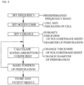
- a method of manufacturing a sound absorbing board using a honeycomb in which the sound absorbing board is formed by laminating glass fiber mats (20) on both surfaces of the honeycomb (10) and foam-molding polyurethane sheets (30) on surfaces, which are exposed to the outside, of the glass fiber mats (20) according to the present disclosure, includes: a first step of setting a frequency band; a second step of setting the cell size (S) and the thickness (t) of the honeycomb (10); a third step of setting a range of the thickness (t) of the polyurethane sheets (30), a range of the diameter d of perforations (31) to be formed in the polyurethane sheets (30), and the porosity of the perforations (31); a fourth step of obtaining a sound absorption coefficient according to a frequency change by calculating an inherent acoustic impedance of the perforations (31) using variables in the third step while at least the diameter (d) among the thickness (t) of the polyurethane sheets (30)
- the honeycomb (10) may be made of paper, aluminum, or synthetic resin.
- the cell size (S) may be in the range of 5 mm to 15 mm.
- the glass fiber mats (20) may have a surface density of 150 g/m 2 to 1,500 g/m 2 .
- the polyurethane sheets (30) may have a surface density of 150 g/m 2 to 1,500 g/m 2 .
- the diameter (d) of the perforations (31) may be in the range of 0.2 mm to 4 mm.
- An interval between the perforations (31) may be the same as the cell size (S).
- the present disclosure includes a sound absorbing board using a honeycomb, which is manufactured by perforating the polyurethane sheets (30) with the marked diameter (d) of the perforations (31) in the above-described method of manufacturing a sound absorbing board using a honeycomb.
- the perforations (31) may be formed using a laser, a roller or press equipped with several needles, or needles equipped with a servo or cylinder.
- the sound absorbing board using a honeycomb may be a luggage board for a vehicle.
- the objective of a manufacturing method according to the present disclosure is to perforate polyurethane sheets 30 to achieve optimal sound absorption performance in a set frequency band when a sound absorbing board B formed by laminating glass fiber mats 20 on both surfaces of a honeycomb 10 and foam-molding the polyurethane sheets 30 on the surfaces of the glass fiber mats 20, the surfaces being exposed to the outside, is designed.
- a sound absorption coefficient is calculated using a cell size S and a thickness T of a cell 11 of the honeycomb 10, the number, a diameter d, and the porosity of perforations 31 formed in the polyurethane sheets 30 to pass through the cell 11, a position having excellent sound absorption performance in a preset frequency band is perforated, and thus the sound absorption performance can be optimized.
- the perforations 31 are designed to have the same diameter d or at least two types of perforations 31 having different diameters are designed in some cases, and thus the optimal sound absorption performance can be obtained in the preset frequency band.
- the manufacturing method includes five steps, the manufacturing method will be described in detail for each step.
- the sound absorbing board may be used wherever sound absorption performance and structural rigidity are required.
- an example of the sound absorbing board used as a luggage board will be described.
- a first step is a step of setting a frequency band as illustrated in FIG. 3 . That is, since a frequency band varies depending on a place where the sound absorbing board B manufactured according to the present disclosure is to be used, the frequency band for enhancing a sound absorption effect is set among frequency bands generated at the place of use. For example, when the sound absorbing board B is applied to and used in a trunk lid, a frequency band to be removed among frequencies generated in a trunk is the same or similar when the vehicle model is the same but is different when the vehicle model is different. Thus, in this way, the frequency band for obtaining the sound absorption effect in the other frequency bands is set so that the sound absorption performance obtained as the perforations 31, which will be described below, are formed is optimized in this frequency band.
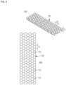
- a second step is a step of setting a cell size S and a thickness T of the honeycomb 10 as illustrated in FIGS. 2 to 4 .
- This is a step of setting the size and the height of each cell 11 constituting the honeycomb 10.
- the cell size S represents a length between facing sides of the cell 11
- the thickness T of the cell 11 represents the thickness of the honeycomb 10.
- the cell size S and the thickness T are set such that the honeycomb 10 is configured to have a thickness T that meets a constraint having occurred in this way. Further, the cell size S is used as an interval between adjacent perforations 31 when the perforations 31, which will be described below, are formed.
- the honeycomb 10 may be made of various materials and used, it is preferable that the honeycomb 10 is manufactured using paper, aluminum, or synthetic resin that is light, is easily formed and may be manufactured and used in a desired size.
- the cell size S is in the range of 5 mm to 15 mm. This is for obtaining sufficient sound absorption performance in a specific frequency band, for example, medium frequency pattern noise (800 Hz), through an inner space of each cell 11 without weakening the structural rigidity of the honeycomb 10.
- a specific frequency band for example, medium frequency pattern noise (800 Hz)
- a third step as illustrated in FIGS. 3 and 4 , the range of the thickness t of the polyurethane sheet 30, the range of the diameter d of the perforation 31 formed in the polyurethane sheet 30, and the porosity of the perforations 31 are set.
- the optimal sound absorption coefficient may be calculated while changing the thickness t and the diameter d.
- the diameter d of the perforation 31 is in the range of 0.2 mm to 4 mm. As described above, this is for further increasing the sound absorption effect by dissipating incident sound energy into thermal energy in each perforation 31 as at least one perforation 31 having a small diameter d is formed in the cell 11 corresponding to one space. In this case, it is preferable that an interval between adjacent perforations 31 is formed to have the cell size S of the cells 11 constituting the honeycomb 10.
- a fourth step is a step of calculating and obtaining the sound absorption performance, as illustrated in FIGS. 3 , 5, and 6 .
- the sound absorption performance in this case is obtained through an inherent acoustic impedance of the perforation 31 used for calculating the sound absorption coefficient based on the variables input in the above-described steps.
- the inherent acoustic impedance of the perforation 31 may be obtained by Equation 1 based on Rao & Munjal's impedance model.
- ⁇ denotes an impedance
- R denotes a real part of the impedance
- X denotes an imaginary part of the impedance
- M denotes the Mach number
- ⁇ denotes the porosity
- t denotes the thickness (the thickness of the polyurethane sheet) of the perforation
- d denotes the diameter of the perforation.
- the sound absorption coefficient using the inherent acoustic impedance ⁇ of the perforation 31 is calculated by repeatedly inputting at least a different diameter d among the thickness t of the polyurethane sheet 30 and the diameter d of the perforation 31.
- This is, for example, for forming only the perforation 31 having the diameter d of 1 mm in the polyurethane sheet 30 having a constant thickness t of 8 mm, for forming perforations 31 having diameters d of 1 mm and 1.5 mm, or forming the perforation 31 having a different larger diameter d.
- the perforation 31 having this diameter d should be marked in a design process such that the perforation 31 may be processed in the polyurethane sheet 30.
- the perforation 31 is formed in the surface of one of the polyurethane sheets 30 formed on both sides based on the honeycomb 10.
- the perforation 31 is formed to pass through the polyurethane sheet 30, and at least one perforation 31 is formed to communicate with the above-described cell 11. This is for sometimes forming at least one perforation 31 in one cell 11 since even in a space having the same porosity, the sound absorption performance becomes more excellent as the number of fine perforations becomes larger.
- the perforation 31 causes the incident sound energy to be dissipated into the thermal energy due to friction, thereby achieving the sound absorption effect.
- the polyurethane sheets 30 are formed by foaming on both sides of the above-described honeycomb 10, preferably, by foaming in a spraying method, and in this case, the sound absorption performance varies depending on the thickness t. Accordingly, the present disclosure is designed such that the range of the thickness t of the polyurethane sheet 30 is determined in advance, and the polyurethane sheet 30 is manufactured with a selected value within the range.
- the polyurethane sheets 30 are formed by foam-molding on surfaces of the glass fiber mats 20 integrally laminated on both sides of the above-described honeycomb 10, the surfaces being exposed to the outside.
- the glass fiber mats 20 are formed in a long fiber state by melting glass in a platinum furnace and dropping the melted glass into a small hole and are made of, in a mat shape, glass fibers which are well known to be used as insulators, air filter media, electrical insulation materials, and sound absorbing materials because the glass fibers have excellent heat resistance, excellent durability, excellent sound absorption, and excellent electrical insulation. It is most preferable that the glass fiber mats 20 having a surface density of 150 g/m 2 to 1,500 g/m 2 are used.
- the perforations 31 are formed in a desired number in a desired position by using a laser, a roller or press equipped with several needles, or a needle equipped with a servo or cylinder when the sound absorbing board B according to the present disclosure is manufactured.
- the polyurethane sheet 30 having the surface density of 150 g/m 2 to 1,500 g/m 2 is used so that a sound absorbing board B that is lightweight and has maximized sound absorption performance is manufactured.
- a fifth step is a step of marking and processing the perforation 31 in the polyurethane sheet 30 based on the above-described sound absorption coefficient obtained in the fourth step, as illustrated in FIGS. 3 and 5 .
- the position marking of the perforation 31 the position of the perforation 31 having a diameter d at which the sound absorption performance is high in the frequency band set in the above-described first step is marked.
- the diameter d of the perforation 31 as described above, one kind of perforation 31 having the same diameter d may be formed or two kinds of perforations 31 having different diameters d may be formed, depending on the frequency band, the thickness t of the polyurethane sheet 30, and the layer configuration of the sound absorbing board B.
- FIG. 5 illustrates an example where one perforation 31 having the same diameter d is formed at the center of each cell 11.
- the sound absorption coefficient is calculated in advance using the variables such as the diameter of the perforation, the thickness of the polyurethane sheet, and the porosity, and the diameter and the thickness of the perforation are determined such that this sound absorption coefficient can increase the sound absorption efficiency in a predetermined frequency band.
- the sound absorbing board having optimal sound absorption performance can be designed.
- the present disclosure includes a sound absorbing board manufactured based on the sound absorption performance obtained by the above-described method of manufacturing a sound absorbing board using a honeycomb.
- the sound absorbing board is manufactured with a variable value having the most excellent sound absorption performance in the predetermined frequency band. Further, it is preferable that such a sound absorbing board is used as a luggage board for a vehicle.
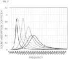
- FIG. 7 is a graph illustrating a result of calculating the sound absorption coefficient through input of a variable using the method of manufacturing a sound absorbing board using a honeycomb according to the present disclosure, wherein a horizontal axis represents a frequency (Hz) and a vertical axis represents the sound absorption coefficient. Further, the graph in FIG. 7 illustrates that the sound absorption coefficient varies depending on the variable used in design.
- FIGs. 8 to 10 illustrate a result of comparing the sound absorption coefficients of three types of luggage boards having different thicknesses according to a frequency change.
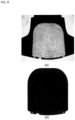
- FIG. 8A illustrates a luggage board.
- FIG. 8B is an enlarged image of a bright part of the center of the luggage board of FIG. 8A , wherein the thickness of an edge was 5 mm, the thickness of a small square part in the center was 6 mm, and the thickness of the remaining part was 8 mm.
- the part having the thickness of 5 mm was not perforated, and the part having the thickness of 6 mm and the part having the thickness of 8 mm were perforated with diameters of 1 mm and 1.5 mm, respectively.
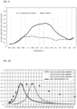
- FIG. 9 is a graph illustrating the comparison between the sound absorption coefficients according to the example in which the actually used luggage board manufactured to have the thicknesses of 5 mm, 6 mm, and 8 mm is perforated as in FIG. 8 and a comparative example in which the luggage board is not perforated, wherein a horizontal axis represents the frequency, a vertical axis represents the sound absorption coefficient, a solid line represents a graph of the sound absorption coefficient according to the embodiment, and a dotted line represents a graph of the sound absorption coefficient according to the comparative example.
- the sound absorption coefficient according to the embodiment is higher than that according to the comparative example in a specific frequency range of about 1 kHz to 8 kHz. This means that, by setting the frequency band, the sound absorption coefficient can be improved in the corresponding frequency band.
- FIG. 10 is a graph obtained by measuring the sound absorption coefficient of the luggage board as in FIG. 8 according to the frequency change and is a graph illustrating a comparison between an actual vehicle test and the sound absorption coefficient obtained by applying three peaks using the perforations having the diameters of 1 mm and 1.5 mm for the parts having the thickness of 6 mm and the thickness of 8 mm.
- a horizontal axis represents the frequency
- a vertical axis represents the sound absorption coefficient
- dots marked in light blue corresponds to a graph of the sound absorption coefficient directly detected using sound absorption coefficient measurement equipment (Alpha Cabin)
- a red line graph and a light green line graph are obtained by theoretically calculating the sound absorption coefficient, wherein the thickness was 8 mm
- a pink line graph was obtained by theoretically calculating the sound absorption coefficient, wherein the perforation had the thickness of 6 mm.
- FIG. 11 illustrates a result a result of an actual vehicle test in a state in which the perforated luggage board according to the example and the non-perforated luggage board according the comparative example are actually mounted in a vehicle.
- a horizontal axis represents a frequency (Hz)
- a vertical axis represents a power based noise reduction (PBNR) (dB)
- a dotted line represents a graph according to the comparative example
- a solid line represents a graph according to the embodiment.
- an excitation point was set as a volume source (Q-SOURCE) in the trunk, and a measurement position was the center of a rear seat.
- Q-SOURCE volume source
- FIG. 12 is a graph obtained by comparing the sound absorption coefficients according to the presence or absence of the perforation in a state in which the perforated luggage board according to the example and the non-perforated luggage board according to the comparative example are manufactured to have the same thickness of 17 mm.
- a horizontal axis represents the frequency (Hz)
- a vertical axis represents the sound absorption coefficient
- a solid line represents the embodiment
- a dotted line represents the comparative example.
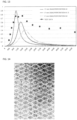
- FIG. 13 is a graph obtained by measuring the sound absorption coefficient in a state in which the perforated luggage board according to the example and the non-perforated luggage board according to the comparative example have the same thickness (17 mm), but the diameters of the perforations are different from each other.
- a horizontal axis represents the frequency (Hz)
- a vertical axis represents the sound absorption coefficient
- a dotted line represents the actually measured sound absorption coefficient
- a blue line represents an example where the luggage board was perforated with a diameter of 1 mm
- a light red line represents an example where the luggage board was perforated with a diameter of 0.5 mm
- a green line represents an example where the luggage board was perforated with a diameter of 2 mm.
- FIG. 14 is a picture illustrating the sound absorbing board manufactured according to the present disclosure.
- a small perforation had a diameter of 1 mm and a large perforation had a diameter of 1.5 mm.
- the method of manufacturing a sound absorbing board using a honeycomb and the sound absorbing board using a honeycomb manufactured using the same according to the present disclosure have the following effects.
Landscapes
- Engineering & Computer Science (AREA)
- Mechanical Engineering (AREA)
- Physics & Mathematics (AREA)
- Acoustics & Sound (AREA)
- Soundproofing, Sound Blocking, And Sound Damping (AREA)
- Vehicle Interior And Exterior Ornaments, Soundproofing, And Insulation (AREA)
- Laminated Bodies (AREA)
Claims (10)
- Procédé de fabrication d'un panneau d'absorption acoustique utilisant un nid d'abeille (10) dans lequel le panneau d'absorption acoustique est formé en laminant des mats de fibre de verre (20) sur les deux surfaces du nid d'abeille (10) et en moulant par mousse des feuilles de polyuréthane (30) sur les surfaces, qui sont exposées à l'extérieur, des mats de fibre de verre (20), le procédé comprenant :une première étape consistant à fixer une bande de fréquence pour l'absorption acoustique ;une deuxième étape consistant à définir la taille des cellules (S) et l'épaisseur (T) du nid d'abeilles (10) ;une troisième étape consistant à définir une plage d'épaisseur (t) des feuilles de polyuréthane (30), une plage de diamètre (d) des perforations (31) à former dans les feuilles de polyuréthane (30), et une porosité des perforations (31) ;une quatrième étape consistant à obtenir une pluralité de coefficients d'absorption acoustique en fonction d'un changement de fréquence en calculant une impédance acoustique inhérente respective des perforations (31) à l'aide de l'équation 1 suivante :
 Où ζ désigne l'impédance acoustique inhérente, R désigne une partie réelle de l'impédance, X désigne une partie imaginaire de l'impédance, M désigne un nombre de Mach, σ désigne la porosité des perforations, t désigne une épaisseur des feuilles de polyuréthane et donc des perforations, et d désigne le diamètre des perforations,tandis que, pour obtenir ladite pluralité de coefficients d'absorption acoustique, au moins l'une des variables suivantes : l'épaisseur (t) des feuilles de polyuréthane (30) et le diamètre (d) des perforations (31), est introduite différemment dans la plage respective fixée à la troisième étape ; etune cinquième étape consistant à marquer les positions des perforations (31) sur au moins une des feuilles de polyuréthane (30) avec au moins un diamètre (d) des perforations (31) pour lequel le coefficient d'absorption acoustique est élevé dans la bande de fréquences définie lors de la première étape parmi les coefficients d'absorption acoustique obtenus lors de la quatrième étape.
 - Procédé de la revendication 1, dans lequel le nid d'abeille (10) est fait de papier, d'aluminium ou de résine synthétique.
- Procédé de la revendication 1, dans lequel la taille des cellules (S) est comprise dans une plage allant de 5 mm à 15 mm.
- Procédé de la revendication 1, dans lequel les mats de fibres de verre (20) ont une densité de surface de 150 g/m2 à 1 500 g/m2.
- Procédé de la revendication 1, dans lequel les feuilles de polyuréthane (30) ont une densité de surface de 150 g/m2 à 1 500 g/m2.
- Procédé de la revendication 1, dans lequel le diamètre des perforations (31) est compris dans une plage allant de 0,2 mm à 4 mm.
- Procédé de la revendication 1, dans lequel l'intervalle entre les perforations (31) est identique à la taille de la cellule (S).
- Procédé de fabrication d'un panneau insonorisant utilisant un nid d'abeille de l'une quelconque des revendications 1 à 7, comprenant la perforation de l'au moins une feuille de polyuréthane (30) pour former des perforations avec un diamètre marqué des perforations (31) selon le marquage de la cinquième étape.
- Procédé de fabrication d'un panneau absorbant acoustique selon la revendication 8, dans lequel les perforations (31) sont formées à l'aide d'un laser, d'un rouleau ou d'une presse équipée de plusieurs aiguilles, ou d'une aiguille équipée d'un servo ou d'un cylindre.
- Procédé de fabrication d'un panneau d'absorption acoustique selon l'une des revendications 1 à 8, dans lequel le panneau d'absorption acoustique en nid d'abeille est un panneau de bagages pour un véhicule.
Applications Claiming Priority (1)
| Application Number | Priority Date | Filing Date | Title |
|---|---|---|---|
| KR1020200035366A KR102162653B1 (ko) | 2020-03-24 | 2020-03-24 | 허니컴을 이용한 흡음 보드의 제조 방법 및 이를 이용한 허니컴을 이용한 흡음 보드 |
Publications (3)
| Publication Number | Publication Date |
|---|---|
| EP3885124A1 EP3885124A1 (fr) | 2021-09-29 |
| EP3885124C0 EP3885124C0 (fr) | 2025-06-18 |
| EP3885124B1 true EP3885124B1 (fr) | 2025-06-18 |
Family
ID=72884639
Family Applications (1)
| Application Number | Title | Priority Date | Filing Date |
|---|---|---|---|
| EP21153505.9A Active EP3885124B1 (fr) | 2020-03-24 | 2021-01-26 | Procédé de fabrication d'un panneau d'absorption sonore utilisant des nids d'abeilles et panneau d'absorption sonore utilisant des nids d'abeilles fabriqué selon ce procédé |
Country Status (3)
| Country | Link |
|---|---|
| EP (1) | EP3885124B1 (fr) |
| JP (1) | JP7330522B2 (fr) |
| KR (1) | KR102162653B1 (fr) |
Families Citing this family (4)
| Publication number | Priority date | Publication date | Assignee | Title |
|---|---|---|---|---|
| KR102502845B1 (ko) * | 2022-03-04 | 2023-02-24 | 주식회사 대솔오시스 | 전기차용 흡음 보드 |
| CN115985277A (zh) * | 2022-10-13 | 2023-04-18 | 哈尔滨工程大学 | 一种含空腔的薄膜型吸声多孔超结构及制备方法 |
| KR102789817B1 (ko) * | 2023-05-30 | 2025-04-03 | (주)대한솔루션 | 복합 인슐레이션 패널 및 그 제조방법 |
| CN118789897A (zh) * | 2024-09-03 | 2024-10-18 | 福州大学 | 一种表面穿孔的蜂窝铝芯吸声板 |
Family Cites Families (10)
| Publication number | Priority date | Publication date | Assignee | Title |
|---|---|---|---|---|
| JP3119192B2 (ja) * | 1997-03-07 | 2000-12-18 | 日産自動車株式会社 | 遮音板構造 |
| BR0110032A (pt) * | 2000-05-29 | 2003-05-27 | Rieter Automotive Int Ag | Estrutura para piso de veìculo leve |
| EP2302620B1 (fr) * | 2008-07-17 | 2021-03-03 | Nagoya Oilchemical Co., Ltd. | Matériau absorbant l'impact et le son et structure absorbant le son |
| JP2015102593A (ja) * | 2013-11-21 | 2015-06-04 | リンテック株式会社 | 吸音材 |
| KR20170093423A (ko) | 2016-02-05 | 2017-08-16 | 주식회사 대솔오시스 | 흡차음 성능을 가진 자동차용 러기지 보드 |
| JP6292339B1 (ja) * | 2016-12-25 | 2018-03-14 | 株式会社 静科 | 吸音パネル |
| KR101952485B1 (ko) | 2016-12-29 | 2019-05-10 | 한화큐셀앤드첨단소재 주식회사 | 자동차의 러기지 보드용 샌드위치 판넬 |
| KR20180107424A (ko) * | 2017-03-21 | 2018-10-02 | (주)대한솔루션 | 허니컴을 이용한 자동차용 언더 커버 |
| KR102073212B1 (ko) | 2017-11-24 | 2020-02-05 | 씨아이티 주식회사 | 차량용 러기지 보드 |
| JP7114044B2 (ja) * | 2018-02-07 | 2022-08-08 | 岐阜プラスチック工業株式会社 | 吸音構造体 |
-
2020
- 2020-03-24 KR KR1020200035366A patent/KR102162653B1/ko active Active
-
2021
- 2021-01-07 JP JP2021001399A patent/JP7330522B2/ja active Active
- 2021-01-26 EP EP21153505.9A patent/EP3885124B1/fr active Active
Also Published As
| Publication number | Publication date |
|---|---|
| JP2021152638A (ja) | 2021-09-30 |
| EP3885124C0 (fr) | 2025-06-18 |
| EP3885124A1 (fr) | 2021-09-29 |
| KR102162653B1 (ko) | 2020-10-07 |
| JP7330522B2 (ja) | 2023-08-22 |
Similar Documents
| Publication | Publication Date | Title |
|---|---|---|
| EP3885124B1 (fr) | Procédé de fabrication d'un panneau d'absorption sonore utilisant des nids d'abeilles et panneau d'absorption sonore utilisant des nids d'abeilles fabriqué selon ce procédé | |
| US7743884B2 (en) | Sandwich panel for sound absorption | |
| US8499887B2 (en) | Acoustically optimized cabin wall element | |
| US7631727B2 (en) | Sandwich structure with frequency-selective double wall behavior | |
| US8579079B2 (en) | Soundproofing panel | |
| US9284727B2 (en) | Acoustic barrier support structure | |
| KR102157758B1 (ko) | 방음재 | |
| JP7326649B2 (ja) | 自動車用遮音材 | |
| KR20160130859A (ko) | 다층 흡음 시트 | |
| CN103443372A (zh) | 波纹隔音面板和生产方法 | |
| EP3679232B1 (fr) | Fabrication de panneau de réduction acoustique | |
| CN110588683A (zh) | 一种面向厢体结构低频宽带降噪的复合板 | |
| WO2008053997A1 (fr) | Structure d'absorption du son | |
| CN101228572B (zh) | 具有频率选择双层壁特性的夹层结构 | |
| US20090173572A1 (en) | Sandwich panel for sound absorption | |
| EP3499499B1 (fr) | Panneau anti-résonant et son procédé de fabrication | |
| JP2010085818A (ja) | 吸音材 | |
| JP2009538746A (ja) | 輸送手段の吸音内側クラッディングのためのサンドイッチ部材、特に、航空機胴体部のセルの吸音内側クラッディングのためのサンドイッチ部材 | |
| JP7706175B2 (ja) | 電気自動車用の吸音ボード | |
| CN113593512A (zh) | 多腔复合吸声结构 | |
| WO2020165619A1 (fr) | Structure d'insonorisation | |
| JP2000274472A (ja) | 緩衝装置 | |
| WO2020165647A1 (fr) | Structure de réflexion sonore | |
| AU2010233057A1 (en) | An acoustic panel and a method of manufacturing acoustic panels | |
| DE102019118591B4 (de) | Schallabsorberanordnung |
Legal Events
| Date | Code | Title | Description |
|---|---|---|---|
| PUAI | Public reference made under article 153(3) epc to a published international application that has entered the european phase |
Free format text: ORIGINAL CODE: 0009012 |
|
| STAA | Information on the status of an ep patent application or granted ep patent |
Free format text: STATUS: THE APPLICATION HAS BEEN PUBLISHED |
|
| AK | Designated contracting states |
Kind code of ref document: A1 Designated state(s): AL AT BE BG CH CY CZ DE DK EE ES FI FR GB GR HR HU IE IS IT LI LT LU LV MC MK MT NL NO PL PT RO RS SE SI SK SM TR |
|
| STAA | Information on the status of an ep patent application or granted ep patent |
Free format text: STATUS: REQUEST FOR EXAMINATION WAS MADE |
|
| 17P | Request for examination filed |
Effective date: 20220324 |
|
| RBV | Designated contracting states (corrected) |
Designated state(s): AL AT BE BG CH CY CZ DE DK EE ES FI FR GB GR HR HU IE IS IT LI LT LU LV MC MK MT NL NO PL PT RO RS SE SI SK SM TR |
|
| STAA | Information on the status of an ep patent application or granted ep patent |
Free format text: STATUS: EXAMINATION IS IN PROGRESS |
|
| 17Q | First examination report despatched |
Effective date: 20220601 |
|
| GRAP | Despatch of communication of intention to grant a patent |
Free format text: ORIGINAL CODE: EPIDOSNIGR1 |
|
| STAA | Information on the status of an ep patent application or granted ep patent |
Free format text: STATUS: GRANT OF PATENT IS INTENDED |
|
| INTG | Intention to grant announced |
Effective date: 20250211 |
|
| RIN1 | Information on inventor provided before grant (corrected) |
Inventor name: NAMGUNG, JAEKYUN Inventor name: KWON, MIN HO |
|
| GRAS | Grant fee paid |
Free format text: ORIGINAL CODE: EPIDOSNIGR3 |
|
| GRAA | (expected) grant |
Free format text: ORIGINAL CODE: 0009210 |
|
| STAA | Information on the status of an ep patent application or granted ep patent |
Free format text: STATUS: THE PATENT HAS BEEN GRANTED |
|
| AK | Designated contracting states |
Kind code of ref document: B1 Designated state(s): AL AT BE BG CH CY CZ DE DK EE ES FI FR GB GR HR HU IE IS IT LI LT LU LV MC MK MT NL NO PL PT RO RS SE SI SK SM TR |
|
| REG | Reference to a national code |
Ref country code: GB Ref legal event code: FG4D |
|
| REG | Reference to a national code |
Ref country code: CH Ref legal event code: EP |
|
| REG | Reference to a national code |
Ref country code: DE Ref legal event code: R096 Ref document number: 602021032315 Country of ref document: DE |
|
| REG | Reference to a national code |
Ref country code: CH Ref legal event code: EP |
|
| REG | Reference to a national code |
Ref country code: IE Ref legal event code: FG4D |
|
| U01 | Request for unitary effect filed |
Effective date: 20250708 |
|
| U07 | Unitary effect registered |
Designated state(s): AT BE BG DE DK EE FI FR IT LT LU LV MT NL PT RO SE SI Effective date: 20250714 |
|
| PG25 | Lapsed in a contracting state [announced via postgrant information from national office to epo] |
Ref country code: GR Free format text: LAPSE BECAUSE OF FAILURE TO SUBMIT A TRANSLATION OF THE DESCRIPTION OR TO PAY THE FEE WITHIN THE PRESCRIBED TIME-LIMIT Effective date: 20250919 Ref country code: NO Free format text: LAPSE BECAUSE OF FAILURE TO SUBMIT A TRANSLATION OF THE DESCRIPTION OR TO PAY THE FEE WITHIN THE PRESCRIBED TIME-LIMIT Effective date: 20250918 |
|
| PG25 | Lapsed in a contracting state [announced via postgrant information from national office to epo] |
Ref country code: HR Free format text: LAPSE BECAUSE OF FAILURE TO SUBMIT A TRANSLATION OF THE DESCRIPTION OR TO PAY THE FEE WITHIN THE PRESCRIBED TIME-LIMIT Effective date: 20250618 |
|
| PG25 | Lapsed in a contracting state [announced via postgrant information from national office to epo] |
Ref country code: RS Free format text: LAPSE BECAUSE OF FAILURE TO SUBMIT A TRANSLATION OF THE DESCRIPTION OR TO PAY THE FEE WITHIN THE PRESCRIBED TIME-LIMIT Effective date: 20250918 |
|
| PG25 | Lapsed in a contracting state [announced via postgrant information from national office to epo] |
Ref country code: IS Free format text: LAPSE BECAUSE OF FAILURE TO SUBMIT A TRANSLATION OF THE DESCRIPTION OR TO PAY THE FEE WITHIN THE PRESCRIBED TIME-LIMIT Effective date: 20251018 |
|
| PG25 | Lapsed in a contracting state [announced via postgrant information from national office to epo] |
Ref country code: SM Free format text: LAPSE BECAUSE OF FAILURE TO SUBMIT A TRANSLATION OF THE DESCRIPTION OR TO PAY THE FEE WITHIN THE PRESCRIBED TIME-LIMIT Effective date: 20250618 |
|
| PG25 | Lapsed in a contracting state [announced via postgrant information from national office to epo] |
Ref country code: CZ Free format text: LAPSE BECAUSE OF FAILURE TO SUBMIT A TRANSLATION OF THE DESCRIPTION OR TO PAY THE FEE WITHIN THE PRESCRIBED TIME-LIMIT Effective date: 20250618 |
|
| PG25 | Lapsed in a contracting state [announced via postgrant information from national office to epo] |
Ref country code: PL Free format text: LAPSE BECAUSE OF FAILURE TO SUBMIT A TRANSLATION OF THE DESCRIPTION OR TO PAY THE FEE WITHIN THE PRESCRIBED TIME-LIMIT Effective date: 20250618 |
|
| PG25 | Lapsed in a contracting state [announced via postgrant information from national office to epo] |
Ref country code: SK Free format text: LAPSE BECAUSE OF FAILURE TO SUBMIT A TRANSLATION OF THE DESCRIPTION OR TO PAY THE FEE WITHIN THE PRESCRIBED TIME-LIMIT Effective date: 20250618 |
|
| PG25 | Lapsed in a contracting state [announced via postgrant information from national office to epo] |
Ref country code: ES Free format text: LAPSE BECAUSE OF FAILURE TO SUBMIT A TRANSLATION OF THE DESCRIPTION OR TO PAY THE FEE WITHIN THE PRESCRIBED TIME-LIMIT Effective date: 20250618 |
|
| U20 | Renewal fee for the european patent with unitary effect paid |
Year of fee payment: 6 Effective date: 20260123 |
|
| PLBE | No opposition filed within time limit |
Free format text: ORIGINAL CODE: 0009261 |
|
| STAA | Information on the status of an ep patent application or granted ep patent |
Free format text: STATUS: NO OPPOSITION FILED WITHIN TIME LIMIT |
|
| REG | Reference to a national code |
Ref country code: CH Ref legal event code: L10 Free format text: ST27 STATUS EVENT CODE: U-0-0-L10-L00 (AS PROVIDED BY THE NATIONAL OFFICE) Effective date: 20260430 |