EP3885198B1 - Antriebsanordnung für ein fahrzeug - Google Patents
Antriebsanordnung für ein fahrzeug Download PDFInfo
- Publication number
- EP3885198B1 EP3885198B1 EP20460018.3A EP20460018A EP3885198B1 EP 3885198 B1 EP3885198 B1 EP 3885198B1 EP 20460018 A EP20460018 A EP 20460018A EP 3885198 B1 EP3885198 B1 EP 3885198B1
- Authority
- EP
- European Patent Office
- Prior art keywords
- sealing
- driving arrangement
- housing
- carrier
- arrangement according
- Prior art date
- Legal status (The legal status is an assumption and is not a legal conclusion. Google has not performed a legal analysis and makes no representation as to the accuracy of the status listed.)
- Active
Links
Images




Classifications
-
- B—PERFORMING OPERATIONS; TRANSPORTING
- B60—VEHICLES IN GENERAL
- B60R—VEHICLES, VEHICLE FITTINGS, OR VEHICLE PARTS, NOT OTHERWISE PROVIDED FOR
- B60R16/00—Electric or fluid circuits specially adapted for vehicles and not otherwise provided for; Arrangement of elements of electric or fluid circuits specially adapted for vehicles and not otherwise provided for
- B60R16/02—Electric or fluid circuits specially adapted for vehicles and not otherwise provided for; Arrangement of elements of electric or fluid circuits specially adapted for vehicles and not otherwise provided for electric constitutive elements
- B60R16/0207—Wire harnesses
- B60R16/0215—Protecting, fastening and routing means therefor
- B60R16/0222—Grommets
-
- H—ELECTRICITY
- H02—GENERATION; CONVERSION OR DISTRIBUTION OF ELECTRIC POWER
- H02G—INSTALLATION OF ELECTRIC CABLES OR LINES, OR OF COMBINED OPTICAL AND ELECTRIC CABLES OR LINES
- H02G15/00—Cable fittings
- H02G15/013—Sealing means for cable inlets
-
- H—ELECTRICITY
- H02—GENERATION; CONVERSION OR DISTRIBUTION OF ELECTRIC POWER
- H02G—INSTALLATION OF ELECTRIC CABLES OR LINES, OR OF COMBINED OPTICAL AND ELECTRIC CABLES OR LINES
- H02G3/00—Installations of electric cables or lines or protective tubing therefor in or on buildings, equivalent structures or vehicles
- H02G3/02—Details
- H02G3/06—Joints for connecting lengths of protective tubing or channels, to each other or to casings, e.g. to distribution boxes; Ensuring electrical continuity in the joint
- H02G3/0616—Joints for connecting tubing to casing
- H02G3/0625—Joints for connecting tubing to casing with means for preventing disengagement of conductors
- H02G3/0633—Joints for connecting tubing to casing with means for preventing disengagement of conductors with means urging the conductors to follow a non-straight line
-
- H—ELECTRICITY
- H02—GENERATION; CONVERSION OR DISTRIBUTION OF ELECTRIC POWER
- H02G—INSTALLATION OF ELECTRIC CABLES OR LINES, OR OF COMBINED OPTICAL AND ELECTRIC CABLES OR LINES
- H02G3/00—Installations of electric cables or lines or protective tubing therefor in or on buildings, equivalent structures or vehicles
- H02G3/22—Installations of cables or lines through walls, floors or ceilings, e.g. into buildings
-
- H—ELECTRICITY
- H02—GENERATION; CONVERSION OR DISTRIBUTION OF ELECTRIC POWER
- H02K—DYNAMO-ELECTRIC MACHINES
- H02K5/00—Casings; Enclosures; Supports
- H02K5/04—Casings or enclosures characterised by the shape, form or construction thereof
- H02K5/22—Auxiliary parts of casings not covered by groups H02K5/06-H02K5/20, e.g. shaped to form connection boxes or terminal boxes
-
- B—PERFORMING OPERATIONS; TRANSPORTING
- B60—VEHICLES IN GENERAL
- B60Y—INDEXING SCHEME RELATING TO ASPECTS CROSS-CUTTING VEHICLE TECHNOLOGY
- B60Y2410/00—Constructional features of vehicle sub-units
- B60Y2410/115—Electric wiring; Electric connectors
Definitions
- the present invention refers to a driving arrangement, particularly for driving a vehicle, comprising an electric machine and a housing, in which the electric machine is arranged, the housing having an opening, through which a supply cable for the electric machine extends.
- Driving arrangements that comprise an electric machine arranged within the housing have to be supplied with an electric current provided by one or multiple supply cables. Therefore, it is generally known to provide an opening in the housing, through which the supply cable extends.
- a inside of the housing needs be protected against the ingress of water and/or dust.
- potting is a difficult step of a manufacturing process of the driving arrangement and causes dirt when handling the compound.
- US 2016/163423 discloses a driving arrangement for driving a vehicle according to the preamble of claim 1.
- the invention is based upon the consideration to seal the opening of the housing by means of the carrier, that can be adjusted to the specific shape of the opening, and to realize a sealing between the carrier and the supply cable by means of the sealing sleeve, through which the supply cable extends.
- the feed-through of the supply cable through the opening is simplified since the carrier can be mounted on the wire and attached to the housing.
- the sleeve can be slid over the supply cable and arranged in the through-hole of the carrier in order to form the sealing device. Thereby, dirt and hardly automatable assembly steps that come along with conventional potting technologies can be avoided.
- the sealing sleeve is less rigid than the carrier. This allows to realize the mechanical stability of the feedthrough by means of the carrier on the one hand and to realize the function of sealing the supply cable against the carrier by means of the sealing sleeve on the other hand. Additionally or alternatively, the sealing sleeve may be less rigid than the supply cable. This allows to provide the sealing to rather rigid supply cables that are capable of conducting large amounts of current, particular when using the driving arrangement to drive the vehicle.
- the sealing sleeve is made of rubber and/or the carrier is made of plastic, e.g. polyamide.
- the sealing sleeve comprises an angled portion on its side facing the outside of the housing.
- the supply cable can be bent directly after passing through the opening in order to save mounting space within the driving arrangement.
- the angle portion may have an angle between 30° and 90°.
- the sealing sleeve comprises a sealing lip that extends circumferentially around the supply cable.
- the sealing lip may be arranged at a free end of the sealing sleeve.
- the angled portion is arranged between the sealing lip and the housing.
- the sealing sleeve comprises a circumferential detent that overlaps the carrier on its side facing the inside of the housing. This allows an simplified fixation of the sealing sleeve at the carrier.
- the sealing sleeve comprises a circumferential collar overlapping the carrier on its side facing the outside of the housing.
- the carrier comprises a plate portion that covers an edge of the opening.
- the through-hole may be surrounded by a cylindrical surface of the carrier that extends from the plate portion towards the inside of the housing.
- the sealing sleeve may comprise one or multiple circumferential sealing projections that abut the cylindrical surface. This realizes an effective axial sealing between the carrier and the sealing sleeve.
- the sealing projections are elastically deformed between the supply cable and the carrier.
- the sealing device comprises a sealing ring arranged between the carrier and the opening.
- the sealing ring provides an effective axial sealing between the opening and the carrier.
- the sealing ring extends along an outside surface that is opposite to the cylindrical surface surrounding the through-hole.
- the carrier is fixed to the housing by means of a snap-fit.
- one or multiple snapping means may extend from the carrier, particular from the plate portion, towards the inside of the housing.
- the carrier and/or the opening has or have the shape of the radiused triangle. This allows an optimized shape of the feedthrough when using three supply cables with respect to provide a three- or six-phase alternating current of the electric machine, as described in detail below.
- the carrier has one or two further through-holes.
- a further sealing sleeve is arranged in each further through-hole and a further supply cable extends through the further sealing sleeve.
- a further sealing sleeve is arranged in one of the further through-holes and a further supply cable extends through the further sealing sleeve, wherein the other through-hole is closed.
- the further through-hole or the further through-holes is or are closed. Thereby, a uniform housing may be adapted to different phase configurations of the electric machine.
- the through-hole may be closed by a plug.
- each through-hole is arranged within corner portions of the radiused triangle.
- the housing comprises a further opening through which a supply cable for the electric machine extends, wherein a further sealing device is mounted in the further opening.
- a further sealing device is mounted in the further opening.
- six supply cables may be provided, wherein three supply cables extend through the first opening and three supply cables extend to further opening. Thereby, a six-phase electric machine can be supplied.
- three supply cables are provided, wherein one supply cable may extend though one of the openings and two supply cables extend through the other opening. Thereby, a three-phase electric machine can be supplied.
- the driving arrangement may further comprise an inverter, wherein the or each supply cable is part of an electrical connection between the inverter and the electric machine.
- the sealing device or the sealing devices are arranged within a maintenance box, formed by an outer surface the housing and a removable cover element.
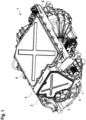
- Fig. 1 is a perspective view of a first embodiment of a driving arrangement 1.
- the driving arrangement 1 is configured to drive the vehicle, such as battery electric vehicle or hybrid vehicle.
- the driving arrangement 1 comprises an electric machine (hidden in fig. 1 ) and a housing 2, in which the electric machine is arranged.
- a shaft 3 that connects the electric machine with the gearbox (hidden in fig. 1 ) is visible in Fig. 1 , which is supported by a bearing arranged within an end shield portion 4 of the housing 2.
- a maintenance box 5 of the driving arrangement 1 is formed by an outer surface 6 (see Fig. 3 ) of the housing 2 and a removable cover 7.
- the driving arrangement 1 comprises an inverter box 8, which is formed by a further outer surface (hidden in Fig. 1 ) of the housing 2 and a further removable cover 9.
- an inverter (hidden in fig. 1 ) is disposed that provides a multiphase AC current for supplying stator windings of the electric machine.
- Fig. 2 is a detailed view of openings 9, 10 of the housing 2 according to the first embodiment.
- the housing has a first opening 9 and a second opening 10 that have the shape of a radiused triangle.
- supply cables (not shown in Fig. 1 to Fig. 8 ) for the electric machine extend.
- the supply cables are a part of an electric connection between the inverter and the electric machine.
- the electric machine in a six-phase synchronous machine, so that six supply cables are provided.
- Fig. 3 is a frontal view of the housing 2 according to the first embodiment.
- the drive arrangement 1 comprises a first sealing device 11 mounted within the first opening 9 (see Fig. 2 ) and the second sealing device 12 mounted within the second opening 10.
- the sealing devices 11, 12 are substantially identical so that they are described in detail with reference to the first sealing device 11 only.
- the sealing device 11 comprises a carrier 13, a first sealing sleeve 14, a second sealing sleep 15 and a third sealing sleeve 16.
- a supply cable extends from the outside of the housing 2 into the inside of the housing 2 in order to connect the electric machine.
- Each sealing sleeve 14, 15, 16 is arranged within one of three through-holes 17a, 17b, 17c (see Fig. 6 ) of the sealing device 11.
- the sealing sleeves 14, 15, 16 and made of rubber, whereas the carrier 13 is made of polyamide and, thus, more rigid than the sealing sleeves 14, 15, 16.
- Fig. 4 is cross-sectional view of the sealing device 11.
- the sealing sleeve 14 also shown in a perspective view in Fig. 5 , is described representatively for the other sealing sleeves 15, 16 of the sealing device 11.
- the sealing sleeve 14 comprises an angled portion 19 which allows the sealing sleeve 14 to follow are corresponding angled shape of the highly rigid cable that extends therethrough.
- the sealing sleeve 14 of the comprises a sealing lip 20 on its free and on the side of the housing to being opposite to the electric machine. Therein, the angled portion 19 is arranged between the sealing lip 20 and the housing 2.
- the other free end of the sealing sleeve 14 comprises a circumferential detent that overlaps the carrier 13 on its side facing the inside of the housing 2. Furthermore, the sealing sleeve 14 comprises two circumferential sealing projections 22 that about a cylindrical surface 23 of the carrier 13. Additionally, the sealing sleeve 14 comprises a circumferential collar 24 overlapping the carrier 13 on its side facing the outside of the housing 2.
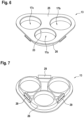
- Fig. 6 and fig. 7 are each a perspective view of the carrier 13.
- the carrier 13 comprises a plate portion 25 from which for each through-hole 17a, 17b, 17c the cylindrical surface 23 extends into the inside of the housing 2.
- the carrier 13 On its side facing the inside of the housing 2 the carrier 13 comprises outside surfaces 26 that the surround of the through-holes 17a, 17b, 17c partially.
- a sealing ring 27 which is shown in a perspective view in Fig. 8 , is arranged between the carrier 13 and an edge 28 of the opening 9.
- the sealing ring 27 is disposed along the outer surfaces 26 of the sealing device 11.
- the sealing device 11 is fixed to the housing 2 by means of a snap-fit that is realized by 3 snapping means 29 (see Fig. 7 ) that are arranged between the outer surfaces 26.
- Fig. 9 is a perspective view of the sealing devices 11, 12 according to a second embodiment of a driving arrangement 1. As far as nothing else is mentioned in the following, the second embodiment corresponds to the first embodiment.
- the electric machine is a three-phase synchronous machine, so that three supply cables 30, 31, 32 are provided.
- the supply cable 30 extends through the first through-hole 17a and the supply cable 31 extends through the second through-hole 17b of the first sealing device 11.
- the third through-hole 17c is closed by means of a plug 33.
- the supply cable 32 extends through the first through-hole 17a of the second sealing device 12.
- the second through-hole 17b and the third through-hole 17c of the second sealing device 12 are closed by means of plugs 33.
- Fig. 10 is a perspective view of the sealing devices 11, 12 according to a third embodiment of a driving arrangement 1. As far as nothing else is mentioned in the following, the second embodiment corresponds to the first embodiment.
- the number of through-holes 17a, 17b of a respective sealing device 11, 12 corresponds to the number of supply cables 30, 31, 22 that extend through the opening 9, 10, in which the sealing device 11, 12 is mounted.
- the plate portion 25 of a respective carrier 13 extends closed in a respective corner portions, where no through-hole is provided.
Landscapes
- Engineering & Computer Science (AREA)
- Architecture (AREA)
- Civil Engineering (AREA)
- Structural Engineering (AREA)
- Mechanical Engineering (AREA)
- Power Engineering (AREA)
- Motor Or Generator Frames (AREA)
- Inverter Devices (AREA)
Claims (15)
- Antriebsanordnung (1), insbesondere zum Antreiben eines Fahrzeugs, umfassend:- eine elektrische Maschine,- ein Gehäuse (2), in dem die elektrische Maschine angeordnet ist, wobei das Gehäuse (2) eine Öffnung (9) aufweist, durch die ein Versorgungskabel (30) für die elektrische Maschine hindurchgeführt ist, und- eine Dichtungseinrichtung (11), die umfasst:- einen Träger (13) mit einer Durchgangsöffnung (17a) und- eine Dichtungshülse (14), die innerhalb der Durchgangsöffnung (17a) angeordnet ist,wobei das Versorgungskabel (30) durch die Dichtungshülse (14) hindurchgeführt ist,dadurch gekennzeichnet, dassder Träger (13) innerhalb der Öffnung (9) angebracht ist und einen Plattenabschnitt (25) umfasst, der einen Rand (28) der Öffnung (9) abdeckt, wobei die Durchgangsöffnung (17a) von einer zylindrischen Fläche (23) des Trägers (13) umgeben ist, die sich von dem Plattenabschnitt (25) in Richtung des Inneren des Gehäuses (2) erstreckt, wobei die Dichtungshülse (14) einen oder mehrere umlaufende Dichtvorsprünge (22) umfasst, die an der zylindrischen Fläche (23) anliegen.
- Antriebsanordnung nach Anspruch 1, wobei die Dichtungshülse (14) weniger steif ist als der Träger (13) und/oder das Versorgungskabel (30).
- Antriebsanordnung nach Anspruch 1 oder 2, wobei die Dichtungshülse einen abgewinkelten Abschnitt (19) auf ihrer der Außenseite des Gehäuses (2) zugewandten Seite umfasst.
- Antriebsanordnung nach einem der vorhergehenden Ansprüche, wobei die Dichtungshülse (14) eine Dichtlippe (20) umfasst, die sich umlaufend um das Versorgungskabel (30) erstreckt.
- Antriebsanordnung nach den Ansprüchen 3 und 4, wobei der abgewinkelte Abschnitt (19) zwischen der Dichtlippe (20) und dem Gehäuse (2) angeordnet ist.
- Antriebsanordnung nach einem der vorhergehenden Ansprüche, wobei die Dichtungshülse (14) eine umlaufende Rastnase (21) umfasst, die auf ihrer dem Inneren des Gehäuses (2) zugewandten Seite den Träger (13) überlappt.
- Antriebsanordnung nach einem der vorhergehenden Ansprüche, wobei der Dichtvorsprung (22) oder die jeweiligen Dichtvorsprünge (22) zwischen dem Versorgungskabel (30) und der Dichtungshülse (14) elastisch verformt ist bzw. sind.
- Antriebsanordnung nach einem der vorhergehenden Ansprüche, wobei die Dichtungseinrichtung (11) einen Dichtungsring (27) umfasst, der zwischen dem Träger (13) und der Öffnung (9) angeordnet ist.
- Antriebsanordnung nach einem der vorhergehenden Ansprüche, wobei der Träger (13) mittels Schnappverbindung an dem Gehäuse befestigt ist.
- Antriebsanordnung nach einem der vorhergehenden Ansprüche, wobei der Träger (13) und/oder die Öffnung (9) die Form eines abgerundeten Dreiecks aufweist bzw. aufweisen.
- Antriebsanordnung nach einem der vorhergehenden Ansprüche, wobei der Träger (13) eine oder zwei weitere Durchgangsöffnungen (17b, 17c) aufweist.
- Antriebsanordnung nach Anspruch 11, wobei:- in jeder weiteren Durchgangsöffnung (17b, 17c) eine weitere Dichtungshülse (15, 16) angeordnet ist und ein weiteres Versorgungskabel (31) durch die weitere Dichtungshülse (15, 16) hindurchgeführt ist,- in einer der zwei weiteren Durchgangsöffnungen (17b) eine weitere Dichtungshülse (15) angeordnet ist und ein weiteres Versorgungskabel (31) durch die weitere Dichtungshülse (15) hindurchgeführt ist, wobei die andere der zwei weiteren Durchgangsöffnungen (17c) verschlossen ist, oder- die weitere Durchgangsöffnung (17b) oder die weiteren Durchgangsöffnungen (17b, 17c) verschlossen ist bzw. sind.
- Antriebsanordnung nach einem der vorhergehenden Ansprüche, wobei das Gehäuse (2) eine weitere Öffnung (10) umfasst, durch die ein Versorgungskabel (32) für die elektrische Maschine hindurchgeführt ist, wobei in der weiteren Öffnung (10) eine weitere Dichtungseinrichtung (12) angebracht ist.
- Antriebsanordnung nach einem der vorhergehenden Ansprüche, wobei die Öffnung (9) oder die Öffnungen (9, 10) innerhalb eines Endschildabschnitts (4) des Gehäuses (2) angeordnet ist bzw. sind.
- Antriebsanordnung nach einem der vorhergehenden Ansprüche, ferner umfassend einen Wechselrichter, wobei das oder jedes Versorgungskabel (30, 31, 32) Teil einer elektrischen Verbindung zwischen dem Wechselrichter und der elektrischen Maschine ist.
Priority Applications (6)
| Application Number | Priority Date | Filing Date | Title |
|---|---|---|---|
| EP20460018.3A EP3885198B1 (de) | 2020-03-27 | 2020-03-27 | Antriebsanordnung für ein fahrzeug |
| US17/914,950 US20230150443A1 (en) | 2020-03-27 | 2021-03-25 | Driving arrangement, particularly for driving the vehicle |
| JP2022552634A JP2023519146A (ja) | 2020-03-27 | 2021-03-25 | 車両のための駆動装置 |
| CN202180025080.4A CN115335262A (zh) | 2020-03-27 | 2021-03-25 | 用于车辆的驱动装置 |
| PCT/EP2021/057685 WO2021191332A1 (en) | 2020-03-27 | 2021-03-25 | Driving arrangement for a vehicle |
| KR1020227033210A KR20220158724A (ko) | 2020-03-27 | 2021-03-25 | 차량용 구동 장치 |
Applications Claiming Priority (1)
| Application Number | Priority Date | Filing Date | Title |
|---|---|---|---|
| EP20460018.3A EP3885198B1 (de) | 2020-03-27 | 2020-03-27 | Antriebsanordnung für ein fahrzeug |
Publications (2)
| Publication Number | Publication Date |
|---|---|
| EP3885198A1 EP3885198A1 (de) | 2021-09-29 |
| EP3885198B1 true EP3885198B1 (de) | 2025-06-18 |
Family
ID=70740563
Family Applications (1)
| Application Number | Title | Priority Date | Filing Date |
|---|---|---|---|
| EP20460018.3A Active EP3885198B1 (de) | 2020-03-27 | 2020-03-27 | Antriebsanordnung für ein fahrzeug |
Country Status (6)
| Country | Link |
|---|---|
| US (1) | US20230150443A1 (de) |
| EP (1) | EP3885198B1 (de) |
| JP (1) | JP2023519146A (de) |
| KR (1) | KR20220158724A (de) |
| CN (1) | CN115335262A (de) |
| WO (1) | WO2021191332A1 (de) |
Families Citing this family (2)
| Publication number | Priority date | Publication date | Assignee | Title |
|---|---|---|---|---|
| DE102022125494A1 (de) * | 2022-10-04 | 2024-04-04 | Liebherr-Werk Nenzing Gmbh | Schutzvorrichtung und Arbeitsmaschine |
| DE102024133627A1 (de) * | 2024-11-18 | 2026-05-21 | Valeo Eautomotive Germany Gmbh | Antriebseinheit für ein Fahrzeug mit einem elastischen Dichtungseinsatz |
Family Cites Families (30)
| Publication number | Priority date | Publication date | Assignee | Title |
|---|---|---|---|---|
| JP3085190B2 (ja) * | 1996-04-22 | 2000-09-04 | 住友電装株式会社 | グロメット |
| JP3684836B2 (ja) * | 1998-04-27 | 2005-08-17 | 矢崎総業株式会社 | グロメット |
| DE19911649A1 (de) * | 1999-03-16 | 2000-09-21 | Volkswagen Ag | Wanddurchführung für strangförmige Körper |
| DE10140714C2 (de) * | 2001-08-24 | 2003-08-14 | Woco Franz Josef Wolf & Co Gmbh | Tülle |
| JP2003226346A (ja) * | 2001-11-30 | 2003-08-12 | Yazaki Corp | 電子部品収納箱の防水構造 |
| US6815615B1 (en) * | 2003-08-29 | 2004-11-09 | Yazaki North America, Inc. | Two-part grommet |
| DE102007015110A1 (de) * | 2007-03-29 | 2008-10-02 | Volkswagen Ag | Dichtendes Durchführungsteil für Leitungen und Kabel |
| US7641271B1 (en) * | 2008-07-03 | 2010-01-05 | Nissan Technical Center North America, Inc. | Vehicle body pass-through structure |
| KR200454270Y1 (ko) * | 2009-07-23 | 2011-06-24 | 주식회사 유라코퍼레이션 | 차량용 그로밋 장치 |
| DE102009056043A1 (de) * | 2009-11-27 | 2011-06-01 | GM Global Technology Operations LLC, ( n. d. Ges. d. Staates Delaware ), Detroit | Dichtungsanordnung für die Kraftfahrzeugstirnwand |
| CN102971465A (zh) * | 2010-06-29 | 2013-03-13 | 沃尔沃建造设备有限公司 | 用于建筑机械驾驶室顶的防水垫圈 |
| US9030063B2 (en) * | 2010-12-17 | 2015-05-12 | Tesla Motors, Inc. | Thermal management system for use with an integrated motor assembly |
| JP5617706B2 (ja) * | 2011-03-14 | 2014-11-05 | 住友電装株式会社 | グロメットのシール構造 |
| JP5747694B2 (ja) * | 2011-07-06 | 2015-07-15 | 住友電装株式会社 | グロメット |
| KR101929586B1 (ko) * | 2012-03-12 | 2019-03-14 | 엘에스전선 주식회사 | 광접속함 |
| DE102012011449A1 (de) * | 2012-06-11 | 2013-12-12 | GM Global Technology Operations LLC (n. d. Ges. d. Staates Delaware) | Kabeldurchführung zur Hindurchführung eines Kabels durch eine Öffnung in einer Wand |
| SE537907C2 (sv) * | 2012-06-29 | 2015-11-17 | Foolproof Ab | Anordning för införing av slang, rör, kabel och liknande i ett mot läckage skyddat utrymme. |
| US8867210B2 (en) * | 2012-10-31 | 2014-10-21 | Deere & Company | Cooling apparatus for an electrical substrate |
| WO2015030012A1 (ja) * | 2013-08-26 | 2015-03-05 | 矢崎総業株式会社 | シールド電線及びワイヤハーネス |
| JP6152822B2 (ja) * | 2014-04-02 | 2017-06-28 | 住友電装株式会社 | グロメット |
| JP2016019436A (ja) * | 2014-07-11 | 2016-02-01 | Ntn株式会社 | 車両用モータ駆動装置のブリーザ構造 |
| US9450327B1 (en) * | 2015-03-13 | 2016-09-20 | Technologies Holdings Corp. | Connector plug with flexible ridges and having a hook with a beveled surface |
| FI127627B (fi) * | 2015-04-08 | 2018-10-31 | Jakotec Oy | Läpivientitiiviste putken läpivientiä varten seinämärakenteessa ja lämmitys- ja/tai käyttövesijärjestelmän kytkentäyksikkö |
| DE102015212593A1 (de) * | 2015-07-06 | 2017-01-12 | Mahle International Gmbh | Dichtungsanordnung und Belüftungs-, Heizungs- oder Klimaanlage mit einer solchen Dichtungsanordnung |
| DE102015012505B4 (de) * | 2015-09-24 | 2017-08-03 | Audi Ag | Dichtungsanordnung für eine Anschlussvorrichtung und Anschlussvorrichtung für eine Klimaanlage |
| JP6642353B2 (ja) * | 2016-09-16 | 2020-02-05 | 住友電装株式会社 | グロメットの車体取付け構造 |
| KR102435827B1 (ko) * | 2017-09-18 | 2022-08-25 | 로베르트 보쉬 게엠베하 | 전기 구동 시스템 |
| FR3086232B1 (fr) * | 2018-09-21 | 2020-10-16 | Psa Automobiles Sa | Manchon de passage d''un faisceau de cables a travers une cloison, notamment un tablier de vehicule automobile. |
| US11420512B2 (en) * | 2019-12-09 | 2022-08-23 | Deere & Company | Integrated transmission with CVP and power electronics apparatus |
| DE102020104994A1 (de) * | 2020-02-26 | 2021-08-26 | Harting Electric Gmbh & Co. Kg | Kabeleinlassvorrichtung für einen Schaltschrank sowie Anordnung und Verfahren zum Betrieb derselben |
-
2020
- 2020-03-27 EP EP20460018.3A patent/EP3885198B1/de active Active
-
2021
- 2021-03-25 JP JP2022552634A patent/JP2023519146A/ja active Pending
- 2021-03-25 WO PCT/EP2021/057685 patent/WO2021191332A1/en not_active Ceased
- 2021-03-25 US US17/914,950 patent/US20230150443A1/en not_active Abandoned
- 2021-03-25 KR KR1020227033210A patent/KR20220158724A/ko not_active Withdrawn
- 2021-03-25 CN CN202180025080.4A patent/CN115335262A/zh active Pending
Also Published As
| Publication number | Publication date |
|---|---|
| WO2021191332A1 (en) | 2021-09-30 |
| JP2023519146A (ja) | 2023-05-10 |
| EP3885198A1 (de) | 2021-09-29 |
| CN115335262A (zh) | 2022-11-11 |
| KR20220158724A (ko) | 2022-12-01 |
| US20230150443A1 (en) | 2023-05-18 |
Similar Documents
| Publication | Publication Date | Title |
|---|---|---|
| US8648507B2 (en) | Stator assembly including a terminal block for an electric machine | |
| CN101884157A (zh) | 驱动装置 | |
| CN114552895B (zh) | 驱动装置 | |
| CN113826311B (zh) | 变速器单元以及具有接线盒的变速器单元的安装 | |
| US7545063B2 (en) | Wire-connection structure of motor | |
| WO2014129288A1 (ja) | モータの集中配電部材 | |
| US20230043493A1 (en) | Electric Machine and Motor Vehicle | |
| US20140062234A1 (en) | Rotating electrical machine | |
| JP4089623B2 (ja) | 回転電機 | |
| US20220311305A1 (en) | Electrical machine comprising a high-voltage connection arrangement and a safety locking device | |
| US20230150443A1 (en) | Driving arrangement, particularly for driving the vehicle | |
| EP3133720B1 (de) | Fahrzeugsteuerungsvorrichtung | |
| CA2444796A1 (en) | Method and apparatus for mounting electronic motor controls | |
| US7687967B2 (en) | Brush assembly for alternator easy to install and capable of reliably preventing entrance of foreign matters | |
| US20130147293A1 (en) | Motor | |
| JP6329835B2 (ja) | 配電部品の端子構造 | |
| WO2018003052A1 (ja) | 回転電機の固定子構造、及び回転電機の固定子構造の組み付け方法 | |
| US11368069B2 (en) | Rotary electric machine unit | |
| JP2005318742A (ja) | 電動モータ | |
| KR102814879B1 (ko) | 전기 구동 모터의 하우징 상에 있는 밀봉 어셈블리 | |
| EP4346070B1 (de) | Elektrische drehmaschine | |
| US20260012058A1 (en) | Enclosed rotating electric machine | |
| CN103026599B (zh) | 带有过滤元件固定部的电动机 | |
| JP2022153953A (ja) | コネクタ、駆動モータモジュール及び車両 | |
| CN115336147A (zh) | 电机 |
Legal Events
| Date | Code | Title | Description |
|---|---|---|---|
| PUAI | Public reference made under article 153(3) epc to a published international application that has entered the european phase |
Free format text: ORIGINAL CODE: 0009012 |
|
| STAA | Information on the status of an ep patent application or granted ep patent |
Free format text: STATUS: THE APPLICATION HAS BEEN PUBLISHED |
|
| AK | Designated contracting states |
Kind code of ref document: A1 Designated state(s): AL AT BE BG CH CY CZ DE DK EE ES FI FR GB GR HR HU IE IS IT LI LT LU LV MC MK MT NL NO PL PT RO RS SE SI SK SM TR |
|
| STAA | Information on the status of an ep patent application or granted ep patent |
Free format text: STATUS: REQUEST FOR EXAMINATION WAS MADE |
|
| 17P | Request for examination filed |
Effective date: 20220328 |
|
| RBV | Designated contracting states (corrected) |
Designated state(s): AL AT BE BG CH CY CZ DE DK EE ES FI FR GB GR HR HU IE IS IT LI LT LU LV MC MK MT NL NO PL PT RO RS SE SI SK SM TR |
|
| GRAP | Despatch of communication of intention to grant a patent |
Free format text: ORIGINAL CODE: EPIDOSNIGR1 |
|
| STAA | Information on the status of an ep patent application or granted ep patent |
Free format text: STATUS: GRANT OF PATENT IS INTENDED |
|
| INTG | Intention to grant announced |
Effective date: 20250129 |
|
| GRAS | Grant fee paid |
Free format text: ORIGINAL CODE: EPIDOSNIGR3 |
|
| GRAA | (expected) grant |
Free format text: ORIGINAL CODE: 0009210 |
|
| STAA | Information on the status of an ep patent application or granted ep patent |
Free format text: STATUS: THE PATENT HAS BEEN GRANTED |
|
| AK | Designated contracting states |
Kind code of ref document: B1 Designated state(s): AL AT BE BG CH CY CZ DE DK EE ES FI FR GB GR HR HU IE IS IT LI LT LU LV MC MK MT NL NO PL PT RO RS SE SI SK SM TR |
|
| REG | Reference to a national code |
Ref country code: GB Ref legal event code: FG4D |
|
| REG | Reference to a national code |
Ref country code: CH Ref legal event code: EP |
|
| REG | Reference to a national code |
Ref country code: DE Ref legal event code: R096 Ref document number: 602020052881 Country of ref document: DE |
|
| REG | Reference to a national code |
Ref country code: CH Ref legal event code: EP |
|
| REG | Reference to a national code |
Ref country code: IE Ref legal event code: FG4D |
|
| PG25 | Lapsed in a contracting state [announced via postgrant information from national office to epo] |
Ref country code: FI Free format text: LAPSE BECAUSE OF FAILURE TO SUBMIT A TRANSLATION OF THE DESCRIPTION OR TO PAY THE FEE WITHIN THE PRESCRIBED TIME-LIMIT Effective date: 20250618 |
|
| REG | Reference to a national code |
Ref country code: LT Ref legal event code: MG9D |
|
| PG25 | Lapsed in a contracting state [announced via postgrant information from national office to epo] |
Ref country code: GR Free format text: LAPSE BECAUSE OF FAILURE TO SUBMIT A TRANSLATION OF THE DESCRIPTION OR TO PAY THE FEE WITHIN THE PRESCRIBED TIME-LIMIT Effective date: 20250919 Ref country code: NO Free format text: LAPSE BECAUSE OF FAILURE TO SUBMIT A TRANSLATION OF THE DESCRIPTION OR TO PAY THE FEE WITHIN THE PRESCRIBED TIME-LIMIT Effective date: 20250918 |
|
| PG25 | Lapsed in a contracting state [announced via postgrant information from national office to epo] |
Ref country code: BG Free format text: LAPSE BECAUSE OF FAILURE TO SUBMIT A TRANSLATION OF THE DESCRIPTION OR TO PAY THE FEE WITHIN THE PRESCRIBED TIME-LIMIT Effective date: 20250618 |
|
| PG25 | Lapsed in a contracting state [announced via postgrant information from national office to epo] |
Ref country code: HR Free format text: LAPSE BECAUSE OF FAILURE TO SUBMIT A TRANSLATION OF THE DESCRIPTION OR TO PAY THE FEE WITHIN THE PRESCRIBED TIME-LIMIT Effective date: 20250618 |
|
| PG25 | Lapsed in a contracting state [announced via postgrant information from national office to epo] |
Ref country code: RS Free format text: LAPSE BECAUSE OF FAILURE TO SUBMIT A TRANSLATION OF THE DESCRIPTION OR TO PAY THE FEE WITHIN THE PRESCRIBED TIME-LIMIT Effective date: 20250918 |
|
| REG | Reference to a national code |
Ref country code: NL Ref legal event code: MP Effective date: 20250618 |
|
| PG25 | Lapsed in a contracting state [announced via postgrant information from national office to epo] |
Ref country code: LV Free format text: LAPSE BECAUSE OF FAILURE TO SUBMIT A TRANSLATION OF THE DESCRIPTION OR TO PAY THE FEE WITHIN THE PRESCRIBED TIME-LIMIT Effective date: 20250618 |
|
| PG25 | Lapsed in a contracting state [announced via postgrant information from national office to epo] |
Ref country code: NL Free format text: LAPSE BECAUSE OF FAILURE TO SUBMIT A TRANSLATION OF THE DESCRIPTION OR TO PAY THE FEE WITHIN THE PRESCRIBED TIME-LIMIT Effective date: 20250618 |
|
| PG25 | Lapsed in a contracting state [announced via postgrant information from national office to epo] |
Ref country code: PT Free format text: LAPSE BECAUSE OF FAILURE TO SUBMIT A TRANSLATION OF THE DESCRIPTION OR TO PAY THE FEE WITHIN THE PRESCRIBED TIME-LIMIT Effective date: 20251020 |
|
| REG | Reference to a national code |
Ref country code: AT Ref legal event code: MK05 Ref document number: 1803929 Country of ref document: AT Kind code of ref document: T Effective date: 20250618 |
|
| PG25 | Lapsed in a contracting state [announced via postgrant information from national office to epo] |
Ref country code: IS Free format text: LAPSE BECAUSE OF FAILURE TO SUBMIT A TRANSLATION OF THE DESCRIPTION OR TO PAY THE FEE WITHIN THE PRESCRIBED TIME-LIMIT Effective date: 20251018 |
|
| PG25 | Lapsed in a contracting state [announced via postgrant information from national office to epo] |
Ref country code: AT Free format text: LAPSE BECAUSE OF FAILURE TO SUBMIT A TRANSLATION OF THE DESCRIPTION OR TO PAY THE FEE WITHIN THE PRESCRIBED TIME-LIMIT Effective date: 20250618 Ref country code: SM Free format text: LAPSE BECAUSE OF FAILURE TO SUBMIT A TRANSLATION OF THE DESCRIPTION OR TO PAY THE FEE WITHIN THE PRESCRIBED TIME-LIMIT Effective date: 20250618 |
|
| PG25 | Lapsed in a contracting state [announced via postgrant information from national office to epo] |
Ref country code: CZ Free format text: LAPSE BECAUSE OF FAILURE TO SUBMIT A TRANSLATION OF THE DESCRIPTION OR TO PAY THE FEE WITHIN THE PRESCRIBED TIME-LIMIT Effective date: 20250618 |
|
| PG25 | Lapsed in a contracting state [announced via postgrant information from national office to epo] |
Ref country code: PL Free format text: LAPSE BECAUSE OF FAILURE TO SUBMIT A TRANSLATION OF THE DESCRIPTION OR TO PAY THE FEE WITHIN THE PRESCRIBED TIME-LIMIT Effective date: 20250618 |
|
| PG25 | Lapsed in a contracting state [announced via postgrant information from national office to epo] |
Ref country code: EE Free format text: LAPSE BECAUSE OF FAILURE TO SUBMIT A TRANSLATION OF THE DESCRIPTION OR TO PAY THE FEE WITHIN THE PRESCRIBED TIME-LIMIT Effective date: 20250618 |
|
| PG25 | Lapsed in a contracting state [announced via postgrant information from national office to epo] |
Ref country code: RO Free format text: LAPSE BECAUSE OF FAILURE TO SUBMIT A TRANSLATION OF THE DESCRIPTION OR TO PAY THE FEE WITHIN THE PRESCRIBED TIME-LIMIT Effective date: 20250618 Ref country code: SK Free format text: LAPSE BECAUSE OF FAILURE TO SUBMIT A TRANSLATION OF THE DESCRIPTION OR TO PAY THE FEE WITHIN THE PRESCRIBED TIME-LIMIT Effective date: 20250618 |
|
| PG25 | Lapsed in a contracting state [announced via postgrant information from national office to epo] |
Ref country code: ES Free format text: LAPSE BECAUSE OF FAILURE TO SUBMIT A TRANSLATION OF THE DESCRIPTION OR TO PAY THE FEE WITHIN THE PRESCRIBED TIME-LIMIT Effective date: 20250618 |
|
| REG | Reference to a national code |
Ref country code: DE Ref legal event code: R097 Ref document number: 602020052881 Country of ref document: DE |
|
| PG25 | Lapsed in a contracting state [announced via postgrant information from national office to epo] |
Ref country code: DK Free format text: LAPSE BECAUSE OF FAILURE TO SUBMIT A TRANSLATION OF THE DESCRIPTION OR TO PAY THE FEE WITHIN THE PRESCRIBED TIME-LIMIT Effective date: 20250618 |
|
| PG25 | Lapsed in a contracting state [announced via postgrant information from national office to epo] |
Ref country code: IT Free format text: LAPSE BECAUSE OF FAILURE TO SUBMIT A TRANSLATION OF THE DESCRIPTION OR TO PAY THE FEE WITHIN THE PRESCRIBED TIME-LIMIT Effective date: 20250618 |
|
| PLBE | No opposition filed within time limit |
Free format text: ORIGINAL CODE: 0009261 |
|
| STAA | Information on the status of an ep patent application or granted ep patent |
Free format text: STATUS: NO OPPOSITION FILED WITHIN TIME LIMIT |
|
| REG | Reference to a national code |
Ref country code: CH Ref legal event code: L10 Free format text: ST27 STATUS EVENT CODE: U-0-0-L10-L00 (AS PROVIDED BY THE NATIONAL OFFICE) Effective date: 20260430 |