EP3885201B1 - Fahrzeug mit einem gesicherten rückfahrsensor - Google Patents
Fahrzeug mit einem gesicherten rückfahrsensor Download PDFInfo
- Publication number
- EP3885201B1 EP3885201B1 EP21159037.7A EP21159037A EP3885201B1 EP 3885201 B1 EP3885201 B1 EP 3885201B1 EP 21159037 A EP21159037 A EP 21159037A EP 3885201 B1 EP3885201 B1 EP 3885201B1
- Authority
- EP
- European Patent Office
- Prior art keywords
- opening
- sensor
- guide element
- vehicle
- crossmember
- Prior art date
- Legal status (The legal status is an assumption and is not a legal conclusion. Google has not performed a legal analysis and makes no representation as to the accuracy of the status listed.)
- Active
Links
Images


Classifications
-
- B—PERFORMING OPERATIONS; TRANSPORTING
- B60—VEHICLES IN GENERAL
- B60R—VEHICLES, VEHICLE FITTINGS, OR VEHICLE PARTS, NOT OTHERWISE PROVIDED FOR
- B60R19/00—Wheel guards; Radiator guards, e.g. grilles; Obstruction removers; Fittings damping bouncing force in collisions
- B60R19/02—Bumpers, i.e. impact receiving or absorbing members for protecting vehicles or fending off blows from other vehicles or objects
- B60R19/48—Bumpers, i.e. impact receiving or absorbing members for protecting vehicles or fending off blows from other vehicles or objects combined with, or convertible into, other devices or objects, e.g. bumpers combined with road brushes, bumpers convertible into beds
- B60R19/483—Bumpers, i.e. impact receiving or absorbing members for protecting vehicles or fending off blows from other vehicles or objects combined with, or convertible into, other devices or objects, e.g. bumpers combined with road brushes, bumpers convertible into beds with obstacle sensors of electric or electronic type
-
- B—PERFORMING OPERATIONS; TRANSPORTING
- B60—VEHICLES IN GENERAL
- B60R—VEHICLES, VEHICLE FITTINGS, OR VEHICLE PARTS, NOT OTHERWISE PROVIDED FOR
- B60R21/00—Arrangements or fittings on vehicles for protecting or preventing injuries to occupants or pedestrians in case of accidents or other traffic risks
- B60R21/01—Electrical circuits for triggering passive safety arrangements, e.g. airbags, safety belt tighteners, in case of vehicle accidents or impending vehicle accidents
- B60R21/013—Electrical circuits for triggering passive safety arrangements, e.g. airbags, safety belt tighteners, in case of vehicle accidents or impending vehicle accidents including means for detecting collisions, impending collisions or roll-over
- B60R21/0136—Electrical circuits for triggering passive safety arrangements, e.g. airbags, safety belt tighteners, in case of vehicle accidents or impending vehicle accidents including means for detecting collisions, impending collisions or roll-over responsive to actual contact with an obstacle, e.g. to vehicle deformation, bumper displacement or bumper velocity relative to the vehicle
-
- B—PERFORMING OPERATIONS; TRANSPORTING
- B60—VEHICLES IN GENERAL
- B60R—VEHICLES, VEHICLE FITTINGS, OR VEHICLE PARTS, NOT OTHERWISE PROVIDED FOR
- B60R19/00—Wheel guards; Radiator guards, e.g. grilles; Obstruction removers; Fittings damping bouncing force in collisions
- B60R19/02—Bumpers, i.e. impact receiving or absorbing members for protecting vehicles or fending off blows from other vehicles or objects
- B60R19/18—Bumpers, i.e. impact receiving or absorbing members for protecting vehicles or fending off blows from other vehicles or objects characterised by the cross-section; Means within the bumper to absorb impact
- B60R2019/1806—Structural beams therefor, e.g. shock-absorbing
Definitions
- the present invention relates to a vehicle provided with a secure reversing sensor.
- X is a front-rear longitudinal axis of the vehicle oriented towards the vehicle.
- Y is a transverse axis directed towards the right of the vehicle and Z is a vertical axis directed upwards.
- US 7,607,705 discloses a vehicle according to the preamble of claim 1.
- Some vehicles have a reversing sensor placed in a rear bumper and intended to inform the driver of the distance that remains to be covered before impacting an object located at the rear of the vehicle. This information is transmitted by means of a beep emitted in the passenger compartment of the vehicle, the frequency of which increases as the vehicle approaches the object, becoming continuous when the vehicle is about to to touch that object.
- this sensor is placed behind a rigid rear cross member of the vehicle, which has been sized to absorb the energy produced during a rear impact of the vehicle against an external object.
- the consequences of such positioning are that, during an accidental impact at very low speed, typically less than 4 km/h, produced against the rear bumper, for example by a driver wishing to park his vehicle by carrying out small maneuvers, the reversing sensor will impact the rear cross member. It may then be damaged and it will have to be changed.
- a first solution to solve this problem was to create an opening in the rear crossmember, placed in front of the sensor, so that the latter could enter said opening while avoiding impacting the rear crossmember, during small shocks produced against the bumper. - rear shocks.
- this opening is not extensible and must have a maximum size, otherwise the damping function of the rear cross member will be impaired.
- the small shocks produced on the rear bumper are not made in a horizontal direction along which the sensor and the opening are aligned, the sensor risks impacting an edge of the crosspiece delimiting said opening. It will then be damaged and will need to be replaced.
- a vehicle according to the invention has a rear cross member designed so that the sensor never comes to impact it during small shocks produced on the rear bumper, including when these shocks are not strictly produced along an axis joining the center of the sensor to the center of the aperture.
- the subject of the invention is a vehicle comprising a rear shock-absorbing crossmember, a rear bumper and a reversing sensor, said sensor being supported by the bumper.
- the crosspiece has an opening located in front of the sensor, and a guide element is fixed to the crosspiece, so as to guide the movement of the sensor towards the opening in the event of an accidental shock at reduced speed caused on the rear bumper by an external object.
- the reversing sensor is moved towards the front of the vehicle in the direction of the rear crossmember, said sensor then coming into contact with a wall of the vehicle. guide element to slide along it, in order to be conveyed to the opening of the rear crosspiece.
- the guide element is configured to prevent a sudden impact of the sensor against the crosspiece by deflecting it towards the opening of said crosspiece. Thanks to the presence of the guide element, the sensor will always be deviated towards the opening of the crosspiece, without the risk of hitting said crosspiece and therefore being damaged.
- the guide element can either form an integral part of the crosspiece and constitute with the latter one and the same piece manufactured in one piece, or constitute an added part which is fixed to the said crosspiece, for example by means of a screwing or clipping.
- the sensor is fixed to a support which is itself secured to the rear bumper, and when small shocks occur on the rear bumper, it is the support which moves towards the rear crossmember.
- the cross member is a part which extends along a transverse axis Y of the vehicle, and which is intended to deform under the effect of a significant impact of an object against the rear bumper in order to protect people who would be seated in a row of rear seats of that vehicle.
- the guide piece comprises at least one wall opening into the opening of the rear crosspiece.
- the opening of the crosspiece has dimensions which are greater than those of the sensor.
- the guide element is configured in such a way that the sensor cannot impact it brutally but can slide along it without a hitch and with a certain smoothness.
- the guide element is a solid part comprising a side wall delimiting a first end opening and a second end opening widened with respect to said first opening, said part being positioned on the crosses so that the first opening is inserted into the opening of said cross and the second opening is placed vis-à-vis the sensor.
- the guide element is a converging hollow part, allowing the reversing sensor, caused to penetrate into the second opening under the effect of small shocks produced on the rear bumper, to slide along the wall side to reach the first opening and thus end up in the opening of the crosspiece.
- the two openings of the guide element are each oblong in shape and are arranged relative to each other while being coaxial.
- the two end openings are inscribed in two parallel planes, and the axis joining the center of said openings is perpendicular to said planes.
- the guide element has a marked character of symmetry and is therefore easy and quick to manufacture.
- it is easy to provide elements for attaching said guide element to said crosspiece.
- the oblong shape of the guide element makes it possible to create an extended space which can advantageously be occupied by equipment, such as for example wiring.
- each of the two openings of the guide element is delimited by two parallel edges connected to each other by two rounded edges.
- This is a particular embodiment of a guide element which is easy to machine.
- the longitudinal axes of the two openings of the guide element are horizontal. This characteristic is true if the vehicle itself rests on level ground.
- the guide element is fixed to the rear crosspiece by clipping.
- This is a simple fixing means, requiring neither specific tools nor complicated manipulations. It can be removed from the crosspiece just as easily, for example by a simple elastic deformation.
- the guide element is made of a hard plastic. In this way, this element is light, while having good mechanical strength. It is also compatible to be elastically deformed in order to be fixed by clipping on the crosspiece or to be removed therefrom.
- the senor is fixed to a support part which is itself secured to the rear bumper.
- this support part to which the sensor is attached which moves towards the rear crossmember.
- the rear crosspiece is made of sheet metal.
- Another object of the invention is a guide element for producing a vehicle according to the invention.
- the invention comprises a side wall delimiting a first end opening and a second end opening widened with respect to said first opening, said two openings each being of oblong shape and being disposed one with respect to being coaxial.
- the two end openings are inscribed in two parallel planes, and the axis joining the center of said openings is perpendicular to said planes.
- a vehicle according to the invention has the advantage of being able to preserve, easily and safely, the reversing sensor when small shocks occur on the rear bumper, thanks to a judicious fixing of a light guide element and simple geometry. It follows that this function safety of the reversing sensor is ensured in the vehicle with mastery, without incurring significant additional costs.
- some vehicle 1 generally comprise a rear cross member 2, a rear bumper and a reversing sensor 3 placed on said rear bumper. More specifically, the sensor 3 is inserted into a support, which is itself secured to the rear bumper. This sensor 3 is activated when the vehicle initiates a reverse gear and approaches an external obstacle, located at the rear of said vehicle 1. This sensor 3 emits beeps, the frequency of which increases when the vehicle approaches the obstacle outside, to turn into a continuous sound when said vehicle 1 is about to touch said obstacle.
- a problem commonly encountered with this type of sensor 3 is that, when for example a second vehicle performs maneuvers behind the present vehicle in an attempt to park, it is likely to impact at least once the rear bumper of said vehicle . It The result is that the reversing sensor 3, which is secured to this rear bumper, risks colliding with the rear crossmember 2 located just in front of it, under the effect of these impacts generally carried out at low speed, typically less than 4 km/h. It is then very likely that sensor 3 will be damaged following this percussion and that it will have to be changed.
- the rear crossmember 2 is preferably made of sheet metal and is configured to be able to deform and thus absorb the energy produced during a significant accidental impact generated at the rear of the vehicle 1, for example by a second vehicle, in order to preserve the physical integrity of people who would be seated inside said vehicle 1.
- This crosspiece 2 is a part which extends along a transverse axis Y of the vehicle, being substantially horizontal.
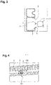
- a first solution considered to prevent the reversing sensor 3 from colliding with the rear crossmember 2 when small shocks occur against the rear bumper was to make an opening 4 in the crossmember 2, located in front of said sensor 3.
- the center of this opening 4 and the center of the sensor 3 are aligned along a longitudinal axis X and horizontal of the vehicle 1.
- this solution is only valid when the sensor 3 is moved horizontally along the along said axis as illustrated by the arrow 5.
- the small shocks against the rear bumper are no longer made in a direction horizontal but in an oblique direction directed downwards, as illustrated by the arrow 6.
- the sensor 3 tends to move downwards and risks coming into contact with a b ord 7 of the crosspiece 2 delimiting the opening 4. The sensor 3 will therefore be damaged and it will have to be changed.
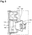
- a vehicle according to the invention implements a second solution to prevent the reversing sensor 3 from colliding with the rear crossmember 2 when small shocks occur against the rear bumper of said vehicle. This involves attaching to the rear crossmember 2 a guide element 100 so as to always orient the movement of the sensor 3 towards the opening 4 of the rear crossmember 2, regardless of the direction of the small shocks produced on the visor. rear shocks.
- the guide element 100 comprises a diverging side wall 101 delimiting an internal channel having a first end opening 102 and a second end opening 103 widened with respect to said first opening 102.
- the cross section of the internal channel gradually increases from the first end opening 102 towards the second end opening 103.
- the two end openings 102, 103 are each delimited by two rectilinear edges 104, 105, 106 , 107 and by two rounded edges 108, 109, 110, 111 connecting said two rectilinear edges 104, 105, 106, 107, said two openings 102, 103 being coaxial.
- the side wall 101 of the guide element 100 has an external bead 112 located on the side of the first end 102, said bead 112 originating on the edge of the wall 101 delimiting the first end 102, and extending over less half the length of said wall and preferably over less than a quarter of said length.
- One end of this bead 112 located on the side of the second end opening 103 defines with said wall 101 a shoulder 113.
- This guide element 100 is advantageously made of a hard plastic, giving said element 100 good mechanical strength and a certain propensity to elastic deformation.
- the guide element 100 is fixed to the crosspiece 2 by clipping. Indeed, this element 100 is introduced into the opening 4 of the rear crosspiece 2 through the first end opening 102. It is then pushed into said opening 4 by deforming elastically until the shoulder 113 has exceeded the wall of said crosspiece 2 delimiting said opening. The bead 112, which was compressed, relaxes behind said wall, then trapping the guide element 100 in the opening 4 of the crosspiece 2.
- the guide element 100 is clipped to the rear crosspiece 2 so that the rectilinear edges 104, 105, 106, 107 of the two end openings 102, 103 extend parallel to a longitudinal axis of said crosspiece 2.
- first end opening 102 is found in front of the second end opening 103, and the reversing sensor 3 which is secured to the rear bumper is placed opposite and behind said second end opening 103.
- the reversing sensor 3 will move forwards and will systematically enter the second end opening 103 of the guide element.
- the dimensions of said second end opening 103 and the arrangement of the recoil sensor 3 with respect to said second opening 103 mean that the sensor 3 can only penetrate into said second end opening 103, whatever the direction of forward movement of said sensor 3.
- Sensor 3 can then either continue its forward progression inside guide element 100 without touching side wall 101, or come into contact with said wall side 101 and then slide along it while being directed towards the first end opening 102 of said guide element. Due to the slope of the side wall 101 of the guide element 100, the bringing into contact of the recoil sensor 3 with said side wall 101 takes place gently, without generating the slightest shock, thus preserving the integrity of said sensor 3.
- Sensor 3 will then end up in opening 4 of crosspiece 2 without ever having impacted said crosspiece 2.
Landscapes
- Engineering & Computer Science (AREA)
- Mechanical Engineering (AREA)
- Air Bags (AREA)
- Body Structure For Vehicles (AREA)
Claims (10)
- Fahrzeug (1), das einen stoßdämpfenden hinteren Querträger (2), einen hinteren Stoßfänger und einen Rückfahrsensor (3) aufweist, wobei der Sensor (3) von dem Stoßfänger getragen wird, dadurch gekennzeichnet, dass der Querträger (2) eine Öffnung (4) aufweist, die vor dem Sensor (3) angeordnet ist, und dass ein Führungselement (100) an dem Querträger (2) befestigt ist, um die Bewegung des Sensors (3) in Richtung der Öffnung (4) zu führen, falls es zu einem unbeabsichtigten Aufprall mit niedriger Geschwindigkeit kommt, der durch ein externes Objekt auf den hinteren Stoßfänger verursacht wird.
- Fahrzeug nach Anspruch 1, dadurch gekennzeichnet, dass das Führungselement (100) ein festes Teil ist, das eine Seitenwand (101) aufweist, die eine erste Endöffnung (102) und eine zweite Endöffnung (103) begrenzt, die in Bezug auf die erste Öffnung (102) erweitert ist, und dass das Teil (100) auf dem Querträger (2) so positioniert ist, dass die erste Öffnung (102) in die Öffnung (4) des Querträgers (2) eingeführt wird und die zweite Öffnung (103) gegenüber dem Sensor (3) angeordnet ist.
- Fahrzeug nach Anspruch 2, dadurch gekennzeichnet, dass die beiden Öffnungen (102, 103) des Führungselements (100) jeweils eine längliche Form aufweisen und koaxial zueinander angeordnet sind.
- Fahrzeug nach Anspruch 3, dadurch gekennzeichnet, dass jede der beiden Öffnungen (102, 103) des Führungselements (100) von zwei parallelen Rändern (104, 105, 106, 107) begrenzt wird, die durch zwei abgerundete Ränder (108, 109, 110, 111) miteinander verbunden sind.
- Fahrzeug nach einem der Ansprüche 3 oder 4, dadurch gekennzeichnet, dass die Längsachsen der beiden Öffnungen (102, 103) des Führungselements (100) horizontal verlaufen.
- Fahrzeug nach einem der Ansprüche 1 bis 5, dadurch gekennzeichnet, dass das Führungselement (100) durch Clipsen an dem hinteren Querträger befestigt ist.
- Fahrzeug nach einem der Ansprüche 1 bis 6, dadurch gekennzeichnet, dass das Führungselement (100) aus einem harten Kunststoff hergestellt ist.
- Fahrzeug nach einem der Ansprüche 1 bis 7, dadurch gekennzeichnet, dass der Sensor (3) an einem Trägerteil befestigt ist, das seinerseits fest mit dem hinteren Stoßfänger verbunden ist.
- Fahrzeug nach einem der Ansprüche 1 bis 8, dadurch gekennzeichnet, dass der hintere Querträger (2) aus Blech besteht.
- Führungselement (100) zur Realisierung eines Fahrzeugs (1) nach einem der Ansprüche 1 bis 9, dadurch gekennzeichnet, dass es eine Seitenwand (101) aufweist, die eine erste Endöffnung (102) und eine zweite Endöffnung (103) begrenzt, die in Bezug auf die erste Öffnung (102) erweitert ist, und dass die beiden Öffnungen (102, 103) jeweils eine längliche Form aufweisen und koaxial zueinander angeordnet sind.
Applications Claiming Priority (1)
| Application Number | Priority Date | Filing Date | Title |
|---|---|---|---|
| FR2002913A FR3108570B1 (fr) | 2020-03-25 | 2020-03-25 | Véhicule doté d’un capteur de recul sécurisé |
Publications (2)
| Publication Number | Publication Date |
|---|---|
| EP3885201A1 EP3885201A1 (de) | 2021-09-29 |
| EP3885201B1 true EP3885201B1 (de) | 2023-01-25 |
Family
ID=70918632
Family Applications (1)
| Application Number | Title | Priority Date | Filing Date |
|---|---|---|---|
| EP21159037.7A Active EP3885201B1 (de) | 2020-03-25 | 2021-02-24 | Fahrzeug mit einem gesicherten rückfahrsensor |
Country Status (2)
| Country | Link |
|---|---|
| EP (1) | EP3885201B1 (de) |
| FR (1) | FR3108570B1 (de) |
Families Citing this family (1)
| Publication number | Priority date | Publication date | Assignee | Title |
|---|---|---|---|---|
| CN115195652A (zh) * | 2022-07-29 | 2022-10-18 | 重庆长安汽车股份有限公司 | 一种汽车前碰撞横梁总成及其加工工艺 |
Family Cites Families (5)
| Publication number | Priority date | Publication date | Assignee | Title |
|---|---|---|---|---|
| DE102004037257A1 (de) * | 2004-07-31 | 2006-02-16 | Robert Bosch Gmbh | Einbauvorrichtung für einen Sensor |
| DE102005032082B3 (de) * | 2005-07-08 | 2006-12-21 | Siemens Ag | Trägerprofil für ein Sensorband zum Einbau in den Stoßfänger eines Kraftfahrzeugs und Sensoranordnung |
| US7607705B1 (en) * | 2008-10-27 | 2009-10-27 | Honda Motor Co., Ltd. | Rear bumper assembly with step garnish |
| KR20130071154A (ko) * | 2011-12-20 | 2013-06-28 | 현대모비스 주식회사 | 자동차의 센서 장치 |
| DE102015209904B4 (de) * | 2015-05-29 | 2020-02-13 | Volkswagen Aktiengesellschaft | Überwachungsvorrichtung für eine Sensoranordnung in einem Kraftfahrzeug |
-
2020
- 2020-03-25 FR FR2002913A patent/FR3108570B1/fr not_active Expired - Fee Related
-
2021
- 2021-02-24 EP EP21159037.7A patent/EP3885201B1/de active Active
Also Published As
| Publication number | Publication date |
|---|---|
| FR3108570B1 (fr) | 2022-04-15 |
| FR3108570A1 (fr) | 2021-10-01 |
| EP3885201A1 (de) | 2021-09-29 |
Similar Documents
| Publication | Publication Date | Title |
|---|---|---|
| EP3927570B1 (de) | Schutzvorrichtung für ein unterhalb einer karosserie angeordnetes kraftfahrzeugbauteil | |
| EP0949092A1 (de) | Stossdämpfer für Kraftfahrzeug | |
| FR3072925B1 (fr) | Dispositif d'amortissement de choc avant d'un vehicule automobile, comprenant un deflecteur d'air basculant et un amortisseur deformable fixes l'un a l''autre. | |
| FR3081820A1 (fr) | Diffuseur arriere mobile de vehicule a panneau escamotable | |
| EP3885201B1 (de) | Fahrzeug mit einem gesicherten rückfahrsensor | |
| EP1595755A1 (de) | Halter für einen Stopper für eine Fahrzeugfronthaube | |
| WO2020011550A1 (fr) | Guide d'air pour vehicule automobile realise d'une piece en materiau polymere expanse et comportant des zones d'absorption de choc | |
| EP3085554B1 (de) | Stossdämpfereinheit, die eine abschleppbuchse umfasst, und fahrzeug, das eine solche stossdämpfereinheit umfasst | |
| EP0719671B1 (de) | Positionierungseinrichtung einer optischen Einheit auf die Fahrzeugskarosserie | |
| EP1755936B1 (de) | Anordnung für ein ersatzrad bei einem kraftfahrzeug | |
| FR3105151A1 (fr) | Structure arriere de caisse de vehicule automobile a plancher polymere et support de batterie | |
| EP3676115B1 (de) | Fahrzeug mit einem hinteren radsatz mit gesteuerter längsverschiebung im falle eines heckaufpralls | |
| EP4001060B1 (de) | Frontstruktur eines kraftfahrzeugs mit frontalaufprallsteuerung mit geringer abdeckung | |
| EP1568552B1 (de) | Anordnung eines Funktionsmoduls auf einem Vorderbau eines Fahrzeugs. | |
| FR2832110A1 (fr) | Poutre de pare-chocs a structure d'entretoise amelioree, module d'extremite longitudinale et vehicule automobile correspondants | |
| EP3199409B1 (de) | Formelement eines belüftungsgitters für die frontseite eines kraftfahrzeugs | |
| EP2108570B1 (de) | Frontteil eines Fahrzeugs, das mit einer Halterung für einen abgeschrägten Kühlergrill ausgestattet ist | |
| EP3009305B1 (de) | Automobil-stossfänger | |
| FR3024969A1 (fr) | Ensemble comportant une traverse de planche de bord et des supports pour fixer cette traverse a la caisse d' vehicule automobile | |
| FR3139524A1 (fr) | Dispositif pour l’assemblage d’un PARECHOC ARRIÈRE de VÉHICULE AUTOMOBILE | |
| WO2015052391A1 (fr) | Dispositif de fixation d'une traverse de poste de conduite d'un vehicule automobile | |
| FR3145326A1 (fr) | Ensemble pour pare-chocs avant de véhicule automobile | |
| FR3125490A1 (fr) | Véhicule automobile avec une structure de caisse comportant un pare-chocs avant | |
| FR3009256A1 (fr) | Voie basse pour vehicule automobile | |
| WO2016012659A1 (fr) | Dispositif de voie basse pour véhicule automobile |
Legal Events
| Date | Code | Title | Description |
|---|---|---|---|
| PUAI | Public reference made under article 153(3) epc to a published international application that has entered the european phase |
Free format text: ORIGINAL CODE: 0009012 |
|
| STAA | Information on the status of an ep patent application or granted ep patent |
Free format text: STATUS: THE APPLICATION HAS BEEN PUBLISHED |
|
| AK | Designated contracting states |
Kind code of ref document: A1 Designated state(s): AL AT BE BG CH CY CZ DE DK EE ES FI FR GB GR HR HU IE IS IT LI LT LU LV MC MK MT NL NO PL PT RO RS SE SI SK SM TR |
|
| RAP3 | Party data changed (applicant data changed or rights of an application transferred) |
Owner name: RENAULT S.A.S |
|
| STAA | Information on the status of an ep patent application or granted ep patent |
Free format text: STATUS: REQUEST FOR EXAMINATION WAS MADE |
|
| 17P | Request for examination filed |
Effective date: 20220323 |
|
| RBV | Designated contracting states (corrected) |
Designated state(s): AL AT BE BG CH CY CZ DE DK EE ES FI FR GB GR HR HU IE IS IT LI LT LU LV MC MK MT NL NO PL PT RO RS SE SI SK SM TR |
|
| RAP3 | Party data changed (applicant data changed or rights of an application transferred) |
Owner name: RENAULT S.A.S |
|
| GRAP | Despatch of communication of intention to grant a patent |
Free format text: ORIGINAL CODE: EPIDOSNIGR1 |
|
| STAA | Information on the status of an ep patent application or granted ep patent |
Free format text: STATUS: GRANT OF PATENT IS INTENDED |
|
| INTG | Intention to grant announced |
Effective date: 20220822 |
|
| GRAS | Grant fee paid |
Free format text: ORIGINAL CODE: EPIDOSNIGR3 |
|
| GRAA | (expected) grant |
Free format text: ORIGINAL CODE: 0009210 |
|
| STAA | Information on the status of an ep patent application or granted ep patent |
Free format text: STATUS: THE PATENT HAS BEEN GRANTED |
|
| AK | Designated contracting states |
Kind code of ref document: B1 Designated state(s): AL AT BE BG CH CY CZ DE DK EE ES FI FR GB GR HR HU IE IS IT LI LT LU LV MC MK MT NL NO PL PT RO RS SE SI SK SM TR |
|
| REG | Reference to a national code |
Ref country code: GB Ref legal event code: FG4D Free format text: NOT ENGLISH |
|
| REG | Reference to a national code |
Ref country code: CH Ref legal event code: EP |
|
| REG | Reference to a national code |
Ref country code: DE Ref legal event code: R096 Ref document number: 602021001288 Country of ref document: DE |
|
| REG | Reference to a national code |
Ref country code: AT Ref legal event code: REF Ref document number: 1545705 Country of ref document: AT Kind code of ref document: T Effective date: 20230215 Ref country code: IE Ref legal event code: FG4D Free format text: LANGUAGE OF EP DOCUMENT: FRENCH |
|
| REG | Reference to a national code |
Ref country code: LT Ref legal event code: MG9D |
|
| REG | Reference to a national code |
Ref country code: NL Ref legal event code: MP Effective date: 20230125 |
|
| REG | Reference to a national code |
Ref country code: AT Ref legal event code: MK05 Ref document number: 1545705 Country of ref document: AT Kind code of ref document: T Effective date: 20230125 |
|
| PG25 | Lapsed in a contracting state [announced via postgrant information from national office to epo] |
Ref country code: NL Free format text: LAPSE BECAUSE OF FAILURE TO SUBMIT A TRANSLATION OF THE DESCRIPTION OR TO PAY THE FEE WITHIN THE PRESCRIBED TIME-LIMIT Effective date: 20230125 |
|
| P01 | Opt-out of the competence of the unified patent court (upc) registered |
Effective date: 20230608 |
|
| PG25 | Lapsed in a contracting state [announced via postgrant information from national office to epo] |
Ref country code: RS Free format text: LAPSE BECAUSE OF FAILURE TO SUBMIT A TRANSLATION OF THE DESCRIPTION OR TO PAY THE FEE WITHIN THE PRESCRIBED TIME-LIMIT Effective date: 20230125 Ref country code: PT Free format text: LAPSE BECAUSE OF FAILURE TO SUBMIT A TRANSLATION OF THE DESCRIPTION OR TO PAY THE FEE WITHIN THE PRESCRIBED TIME-LIMIT Effective date: 20230525 Ref country code: NO Free format text: LAPSE BECAUSE OF FAILURE TO SUBMIT A TRANSLATION OF THE DESCRIPTION OR TO PAY THE FEE WITHIN THE PRESCRIBED TIME-LIMIT Effective date: 20230425 Ref country code: LV Free format text: LAPSE BECAUSE OF FAILURE TO SUBMIT A TRANSLATION OF THE DESCRIPTION OR TO PAY THE FEE WITHIN THE PRESCRIBED TIME-LIMIT Effective date: 20230125 Ref country code: LT Free format text: LAPSE BECAUSE OF FAILURE TO SUBMIT A TRANSLATION OF THE DESCRIPTION OR TO PAY THE FEE WITHIN THE PRESCRIBED TIME-LIMIT Effective date: 20230125 Ref country code: HR Free format text: LAPSE BECAUSE OF FAILURE TO SUBMIT A TRANSLATION OF THE DESCRIPTION OR TO PAY THE FEE WITHIN THE PRESCRIBED TIME-LIMIT Effective date: 20230125 Ref country code: ES Free format text: LAPSE BECAUSE OF FAILURE TO SUBMIT A TRANSLATION OF THE DESCRIPTION OR TO PAY THE FEE WITHIN THE PRESCRIBED TIME-LIMIT Effective date: 20230125 Ref country code: AT Free format text: LAPSE BECAUSE OF FAILURE TO SUBMIT A TRANSLATION OF THE DESCRIPTION OR TO PAY THE FEE WITHIN THE PRESCRIBED TIME-LIMIT Effective date: 20230125 |
|
| PG25 | Lapsed in a contracting state [announced via postgrant information from national office to epo] |
Ref country code: SE Free format text: LAPSE BECAUSE OF FAILURE TO SUBMIT A TRANSLATION OF THE DESCRIPTION OR TO PAY THE FEE WITHIN THE PRESCRIBED TIME-LIMIT Effective date: 20230125 Ref country code: PL Free format text: LAPSE BECAUSE OF FAILURE TO SUBMIT A TRANSLATION OF THE DESCRIPTION OR TO PAY THE FEE WITHIN THE PRESCRIBED TIME-LIMIT Effective date: 20230125 Ref country code: IS Free format text: LAPSE BECAUSE OF FAILURE TO SUBMIT A TRANSLATION OF THE DESCRIPTION OR TO PAY THE FEE WITHIN THE PRESCRIBED TIME-LIMIT Effective date: 20230525 Ref country code: GR Free format text: LAPSE BECAUSE OF FAILURE TO SUBMIT A TRANSLATION OF THE DESCRIPTION OR TO PAY THE FEE WITHIN THE PRESCRIBED TIME-LIMIT Effective date: 20230426 Ref country code: FI Free format text: LAPSE BECAUSE OF FAILURE TO SUBMIT A TRANSLATION OF THE DESCRIPTION OR TO PAY THE FEE WITHIN THE PRESCRIBED TIME-LIMIT Effective date: 20230125 |
|
| REG | Reference to a national code |
Ref country code: BE Ref legal event code: MM Effective date: 20230228 |
|
| REG | Reference to a national code |
Ref country code: DE Ref legal event code: R097 Ref document number: 602021001288 Country of ref document: DE |
|
| PG25 | Lapsed in a contracting state [announced via postgrant information from national office to epo] |
Ref country code: SM Free format text: LAPSE BECAUSE OF FAILURE TO SUBMIT A TRANSLATION OF THE DESCRIPTION OR TO PAY THE FEE WITHIN THE PRESCRIBED TIME-LIMIT Effective date: 20230125 Ref country code: RO Free format text: LAPSE BECAUSE OF FAILURE TO SUBMIT A TRANSLATION OF THE DESCRIPTION OR TO PAY THE FEE WITHIN THE PRESCRIBED TIME-LIMIT Effective date: 20230125 Ref country code: MC Free format text: LAPSE BECAUSE OF FAILURE TO SUBMIT A TRANSLATION OF THE DESCRIPTION OR TO PAY THE FEE WITHIN THE PRESCRIBED TIME-LIMIT Effective date: 20230125 Ref country code: LU Free format text: LAPSE BECAUSE OF NON-PAYMENT OF DUE FEES Effective date: 20230224 Ref country code: EE Free format text: LAPSE BECAUSE OF FAILURE TO SUBMIT A TRANSLATION OF THE DESCRIPTION OR TO PAY THE FEE WITHIN THE PRESCRIBED TIME-LIMIT Effective date: 20230125 Ref country code: DK Free format text: LAPSE BECAUSE OF FAILURE TO SUBMIT A TRANSLATION OF THE DESCRIPTION OR TO PAY THE FEE WITHIN THE PRESCRIBED TIME-LIMIT Effective date: 20230125 Ref country code: CZ Free format text: LAPSE BECAUSE OF FAILURE TO SUBMIT A TRANSLATION OF THE DESCRIPTION OR TO PAY THE FEE WITHIN THE PRESCRIBED TIME-LIMIT Effective date: 20230125 |
|
| PG25 | Lapsed in a contracting state [announced via postgrant information from national office to epo] |
Ref country code: SK Free format text: LAPSE BECAUSE OF FAILURE TO SUBMIT A TRANSLATION OF THE DESCRIPTION OR TO PAY THE FEE WITHIN THE PRESCRIBED TIME-LIMIT Effective date: 20230125 |
|
| PLBE | No opposition filed within time limit |
Free format text: ORIGINAL CODE: 0009261 |
|
| STAA | Information on the status of an ep patent application or granted ep patent |
Free format text: STATUS: NO OPPOSITION FILED WITHIN TIME LIMIT |
|
| REG | Reference to a national code |
Ref country code: IE Ref legal event code: MM4A |
|
| 26N | No opposition filed |
Effective date: 20231026 |
|
| PG25 | Lapsed in a contracting state [announced via postgrant information from national office to epo] |
Ref country code: SI Free format text: LAPSE BECAUSE OF FAILURE TO SUBMIT A TRANSLATION OF THE DESCRIPTION OR TO PAY THE FEE WITHIN THE PRESCRIBED TIME-LIMIT Effective date: 20230125 Ref country code: IE Free format text: LAPSE BECAUSE OF NON-PAYMENT OF DUE FEES Effective date: 20230224 |
|
| PG25 | Lapsed in a contracting state [announced via postgrant information from national office to epo] |
Ref country code: BE Free format text: LAPSE BECAUSE OF NON-PAYMENT OF DUE FEES Effective date: 20230228 |
|
| PG25 | Lapsed in a contracting state [announced via postgrant information from national office to epo] |
Ref country code: IT Free format text: LAPSE BECAUSE OF FAILURE TO SUBMIT A TRANSLATION OF THE DESCRIPTION OR TO PAY THE FEE WITHIN THE PRESCRIBED TIME-LIMIT Effective date: 20230125 |
|
| REG | Reference to a national code |
Ref country code: CH Ref legal event code: PL |
|
| PG25 | Lapsed in a contracting state [announced via postgrant information from national office to epo] |
Ref country code: CH Free format text: LAPSE BECAUSE OF NON-PAYMENT OF DUE FEES Effective date: 20240229 |
|
| PG25 | Lapsed in a contracting state [announced via postgrant information from national office to epo] |
Ref country code: CH Free format text: LAPSE BECAUSE OF NON-PAYMENT OF DUE FEES Effective date: 20240229 |
|
| PG25 | Lapsed in a contracting state [announced via postgrant information from national office to epo] |
Ref country code: BG Free format text: LAPSE BECAUSE OF FAILURE TO SUBMIT A TRANSLATION OF THE DESCRIPTION OR TO PAY THE FEE WITHIN THE PRESCRIBED TIME-LIMIT Effective date: 20230125 |
|
| PG25 | Lapsed in a contracting state [announced via postgrant information from national office to epo] |
Ref country code: BG Free format text: LAPSE BECAUSE OF FAILURE TO SUBMIT A TRANSLATION OF THE DESCRIPTION OR TO PAY THE FEE WITHIN THE PRESCRIBED TIME-LIMIT Effective date: 20230125 |
|
| PG25 | Lapsed in a contracting state [announced via postgrant information from national office to epo] |
Ref country code: CY Free format text: LAPSE BECAUSE OF FAILURE TO SUBMIT A TRANSLATION OF THE DESCRIPTION OR TO PAY THE FEE WITHIN THE PRESCRIBED TIME-LIMIT; INVALID AB INITIO Effective date: 20210224 |
|
| PG25 | Lapsed in a contracting state [announced via postgrant information from national office to epo] |
Ref country code: HU Free format text: LAPSE BECAUSE OF FAILURE TO SUBMIT A TRANSLATION OF THE DESCRIPTION OR TO PAY THE FEE WITHIN THE PRESCRIBED TIME-LIMIT; INVALID AB INITIO Effective date: 20210224 |
|
| PG25 | Lapsed in a contracting state [announced via postgrant information from national office to epo] |
Ref country code: TR Free format text: LAPSE BECAUSE OF FAILURE TO SUBMIT A TRANSLATION OF THE DESCRIPTION OR TO PAY THE FEE WITHIN THE PRESCRIBED TIME-LIMIT Effective date: 20230125 |
|
| PGFP | Annual fee paid to national office [announced via postgrant information from national office to epo] |
Ref country code: GB Payment date: 20260220 Year of fee payment: 6 |
|
| PGFP | Annual fee paid to national office [announced via postgrant information from national office to epo] |
Ref country code: DE Payment date: 20260218 Year of fee payment: 6 |
|
| PGFP | Annual fee paid to national office [announced via postgrant information from national office to epo] |
Ref country code: FR Payment date: 20260218 Year of fee payment: 6 |