EP3885231A1 - Schienenfahrzeug und entsprechendes verfahren - Google Patents
Schienenfahrzeug und entsprechendes verfahren Download PDFInfo
- Publication number
- EP3885231A1 EP3885231A1 EP21163907.5A EP21163907A EP3885231A1 EP 3885231 A1 EP3885231 A1 EP 3885231A1 EP 21163907 A EP21163907 A EP 21163907A EP 3885231 A1 EP3885231 A1 EP 3885231A1
- Authority
- EP
- European Patent Office
- Prior art keywords
- proximity sensor
- distance
- bogie
- spacing
- rail vehicle
- Prior art date
- Legal status (The legal status is an assumption and is not a legal conclusion. Google has not performed a legal analysis and makes no representation as to the accuracy of the status listed.)
- Granted
Links
Images
Classifications
-
- B—PERFORMING OPERATIONS; TRANSPORTING
- B61—RAILWAYS
- B61F—RAIL VEHICLE SUSPENSIONS, e.g. UNDERFRAMES, BOGIES OR ARRANGEMENTS OF WHEEL AXLES; RAIL VEHICLES FOR USE ON TRACKS OF DIFFERENT WIDTH; PREVENTING DERAILING OF RAIL VEHICLES; WHEEL GUARDS, OBSTRUCTION REMOVERS OR THE LIKE FOR RAIL VEHICLES
- B61F5/00—Constructional details of bogies; Connections between bogies and vehicle underframes; Arrangements or devices for adjusting or allowing self-adjustment of wheel axles or bogies when rounding curves
- B61F5/02—Arrangements permitting limited transverse relative movements between vehicle underframe or bolster and bogie; Connections between underframes and bogies
- B61F5/22—Guiding of the vehicle underframes with respect to the bogies
-
- B—PERFORMING OPERATIONS; TRANSPORTING
- B60—VEHICLES IN GENERAL
- B60G—VEHICLE SUSPENSION ARRANGEMENTS
- B60G17/00—Resilient suspensions having means for adjusting the spring or vibration-damper characteristics, for regulating the distance between a supporting surface and a sprung part of vehicle or for locking suspension during use to meet varying vehicular or surface conditions, e.g. due to speed or load
- B60G17/015—Resilient suspensions having means for adjusting the spring or vibration-damper characteristics, for regulating the distance between a supporting surface and a sprung part of vehicle or for locking suspension during use to meet varying vehicular or surface conditions, e.g. due to speed or load the regulating means comprising electric or electronic elements
- B60G17/019—Resilient suspensions having means for adjusting the spring or vibration-damper characteristics, for regulating the distance between a supporting surface and a sprung part of vehicle or for locking suspension during use to meet varying vehicular or surface conditions, e.g. due to speed or load the regulating means comprising electric or electronic elements characterised by the type of sensor or the arrangement thereof
-
- B—PERFORMING OPERATIONS; TRANSPORTING
- B60—VEHICLES IN GENERAL
- B60G—VEHICLE SUSPENSION ARRANGEMENTS
- B60G17/00—Resilient suspensions having means for adjusting the spring or vibration-damper characteristics, for regulating the distance between a supporting surface and a sprung part of vehicle or for locking suspension during use to meet varying vehicular or surface conditions, e.g. due to speed or load
- B60G17/02—Spring characteristics, e.g. mechanical springs and mechanical adjusting means
- B60G17/04—Spring characteristics, e.g. mechanical springs and mechanical adjusting means fluid spring characteristics
- B60G17/052—Pneumatic spring characteristics
-
- B—PERFORMING OPERATIONS; TRANSPORTING
- B60—VEHICLES IN GENERAL
- B60G—VEHICLE SUSPENSION ARRANGEMENTS
- B60G2204/00—Indexing codes related to suspensions per se or to auxiliary parts
- B60G2204/10—Mounting of suspension elements
- B60G2204/11—Mounting of sensors thereon
-
- B—PERFORMING OPERATIONS; TRANSPORTING
- B60—VEHICLES IN GENERAL
- B60G—VEHICLE SUSPENSION ARRANGEMENTS
- B60G2300/00—Indexing codes relating to the type of vehicle
- B60G2300/10—Railway vehicles
-
- B—PERFORMING OPERATIONS; TRANSPORTING
- B60—VEHICLES IN GENERAL
- B60G—VEHICLE SUSPENSION ARRANGEMENTS
- B60G2401/00—Indexing codes relating to the type of sensors based on the principle of their operation
-
- B—PERFORMING OPERATIONS; TRANSPORTING
- B60—VEHICLES IN GENERAL
- B60G—VEHICLE SUSPENSION ARRANGEMENTS
- B60G2401/00—Indexing codes relating to the type of sensors based on the principle of their operation
- B60G2401/17—Magnetic/Electromagnetic
- B60G2401/172—Hall effect
-
- B—PERFORMING OPERATIONS; TRANSPORTING
- B60—VEHICLES IN GENERAL
- B60G—VEHICLE SUSPENSION ARRANGEMENTS
- B60G2500/00—Indexing codes relating to the regulated action or device
- B60G2500/30—Height or ground clearance
-
- B—PERFORMING OPERATIONS; TRANSPORTING
- B60—VEHICLES IN GENERAL
- B60G—VEHICLE SUSPENSION ARRANGEMENTS
- B60G2600/00—Indexing codes relating to particular elements, systems or processes used on suspension systems or suspension control systems
- B60G2600/02—Retarders, delaying means, dead zones, threshold values, cut-off frequency, timer interruption
Definitions
- the present invention relates to a railway vehicle comprising at least one bogie, at least one body, and at least one secondary suspension connecting the body and the bogie, the body and the bogie defining a variable spacing in a direction of elevation of the rail vehicle.
- the present invention also relates to a method implementing such a vehicle.
- the present invention relates in particular to the arrangement of the body relative to the bogie.
- the spacing between the body and the bogie is typically variable. For example, when the rail vehicle is carrying a high load, the body transmits a high force through the secondary suspensions to the bogie and the spacing is reduced accordingly. It is thus necessary to control the spacing.
- mechanical devices comprising a measuring arm capable of moving with one of the body and the bogie.
- the arm includes a graduation allowing, for example, an operator to note the spacing.
- the spacing is for example modified by filling air in air cushions of the secondary suspensions or by purging part of the air included in air cushions.
- An object of the present invention is thus to obtain a railway vehicle allowing a simpler way of controlling the spacing between the body and the bogie, while being reliable.
- the invention relates to a railway vehicle of the type described above, in which the railway vehicle comprises at least a first proximity sensor connected to one of the body and of the bogie, the first proximity sensor being configured to detect, in particular by induction, the presence of a first surface of the other of the bogie and of the body when the spacing is less than or equal to a first threshold, and in which the rail vehicle comprises at least a second proximity sensor connected to one of the body and to the bogie, the second proximity sensor being configured to detect, in particular by induction, the presence of a second surface of the other the bogie and the body when the spacing is less than or equal to a second threshold, distinct from the first threshold.
- the rail vehicle 1 is for example a high speed train, a suburban train, a metro or a tram.
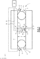
- the rail vehicle 1 comprises a bogie 2, a body 4, and two secondary suspensions 6 connecting the body 4 and the bogie 2.
- the rail vehicle 1 comprises several bogies and / or several boxes.
- the rail vehicle 1 comprises a single secondary suspension or at least three secondary suspensions.
- the bogie 2 is configured to hold the axles and wheels via primary suspensions, not shown.
- the bogie 2 is configured to support the body 4 via the secondary suspensions 6.
- the direction of elevation E is vertical when the rail vehicle 1 is traveling on horizontal rails.
- a longitudinal direction L is also defined which is substantially perpendicular to the direction of elevation E and corresponds to the direction of movement of the rail vehicle 1.
- transverse direction T substantially perpendicular to the direction of elevation E and to the longitudinal direction L.
- Each secondary suspension 6 comprises for example an air cushion 10 maintaining the spacing between the bogie 2 and the body 4.
- Each air cushion 10 has for example an opening 12, provided with an air control device 14, such as a solenoid valve.
- the air control device 14 is configured to supply air to the air bag 10 or to release air from the air bag 10.
- the spacing 8 is increased.
- the distance between the body 4 and the bogie 2 in the direction of elevation E is thus increased.
- the rail vehicle 1 comprises a first proximity sensor 16 and a second proximity sensor 18.
- each proximity sensor 16, 18 is an induction sensor.
- proximity sensor and in particular by “induction sensor”, is meant a device configured to generate a magnetic field and to detect the presence of a metal part in the magnetic field, in particular by induction.
- each proximity sensor 16, 18 is configured to detect a surface of the metal part, such as part of the bogie 2 or of the body 4.
- the first proximity sensor 16 and the second proximity sensor 18 are attached to the body 4.
- the first proximity sensor 16 is configured to detect, for example by induction, the presence of a first surface 20 when the spacing 8 is less than or equal to a first threshold.
- the second proximity sensor 18 is configured to detect, for example by induction, the presence of a second surface 22 when the spacing 8 is less than or equal to a second threshold distinct from the first threshold.
- the first threshold is for example a predetermined maximum threshold of the spacing 8 and the second threshold is for example a predetermined minimum threshold of the spacing 8.
- the predetermined maximum threshold is between 45 mm and 55 mm and the threshold predetermined minimum is between 25 mm and 35 mm.
- the first threshold is a single predetermined minimum and the second threshold is a predetermined maximum threshold of the spacing 8.
- first surface 20 and the second surface 22 are surfaces of the bogie 2.
- first surface 20 coincides with the second surface 22.
- the first surface 20 differs from the second surface 22.
- the first surface 20 is a surface of the bogie 2 and the second surface 22 is a surface of the body 4 or vice versa.
- At least one of the first and second sensors 16, 18 is fixed to the bogie 2.
- the first and / or the second surface 20, 22 are in particular surfaces of the body 4.
- the first proximity sensor 16 and the second proximity sensor 18 are directly attached to the body 4.
- the first proximity sensor 16 and the second proximity sensor 18 are arranged inside the space 8.
- At least one of the first proximity sensor 16 and the second proximity sensor 18 is fixed inside the air cushion 10.
- This proximity sensor 16, 18 is for example connected to one of the body 4 and of the bogie 2 via the air cushion 10.
- the proximity sensor 16, 18, according to the example, is configured to detect the presence of one surface of the other of the bogie 2 and of the body 4, via a part of the air cushion 10 covering this surface.
- the first and the second proximity sensor 16, 18 form a set of sensors.
- the railway vehicle 1 comprises a set of sensors per secondary suspension 6.
- the railway vehicle 1 comprises a set of sensors per bogie 2.
- the railway vehicle 1 comprises several sets of sensors. by secondary suspension 6 and / or by bogie 2.
- the first and / or the second surface 20, 22 are substantially perpendicular to the direction of elevation E.
- substantially perpendicular is meant a relation of perpendicularity to plus or minus 10 degrees, preferably plus or minus 5 degrees.
- the first proximity sensor 16 is arranged at a first distance 24 from the first surface 20, and the second proximity sensor 18 is arranged at a second distance 26 from the second surface 22.
- the first and the second distance 24 , 26 are for example defined according to the direction of elevation E.
- Each proximity sensor 16, 18 has for example an emitting surface 27.
- the first distance 24 is for example the distance between the emitting surface 27 of the first proximity sensor 16 and the first surface 20.
- the second distance 26 is for example the distance between the emitting surface 27 of the second proximity sensor 18 and the second surface. 22.
- the second distance 26 is distinct from the first distance 24.
- the first proximity sensor 16 is for example configured to generate a magnetic field C1 having a first frequency.
- the second proximity sensor 18 is for example configured to generate a magnetic field C2 having a second frequency, for example distinct from the first frequency. The fact that the second frequency is distinct from the first frequency makes it possible to avoid interference between the magnetic field C1 generated by the first proximity sensor 16 and the magnetic field C2 generated by the second proximity sensor 18.
- the first frequency is equal to the second frequency.
- the first proximity sensor 16 is configured to generate the magnetic field C1 at different times from the generation of the magnetic field C2 by the second proximity sensor 18. This also makes it possible to avoid interference.
- Each proximity sensor 16, 18 has for example a detection range.
- detection range is meant the range of distances in which the proximity sensor 16, 18 is capable of detecting the first or second surface 20, 22.
- the detection range is for example between 0 cm and 50 cm, preferably between 0 cm and 5 cm.
- Each proximity sensor 16, 18 has for example a maximum detection range.
- maximum detection range is meant the maximum distance at which the proximity sensor 16, 18 is capable of detecting the first or second surface 20, 22.
- each proximity sensor 16, 18 is configured to detect the first or second surface 20, 22, in particular a metal surface, by induction when this surface is present at a distance 24, 26 with respect to the proximity sensor 16, 18 which is less than the maximum detection range of the sensor.
- the maximum detection range is for example between 1 cm and 50 cm, preferably between 1 cm and 5 cm.
- each proximity sensor 16, 18 is not able to measure the distance between this proximity sensor and the surface 20, 22, but only to detect the presence of the surface 20, 22.
- the induction generated by the surface 20, 22 is less than a threshold of a minimum induction for detection, and the surface 20 , 22 is thus not detected by the proximity sensor 16, 18.
- the first proximity sensor 16 has a first maximum detection range according to the direction of elevation E.
- the first proximity sensor 16 is thus configured to detect the presence of the first surface 20, when the distance between this surface 20 and the first proximity sensor 16 is less than or equal to the first maximum detection range.
- the second proximity sensor 18 has for example a second maximum detection range in the direction of elevation E.
- the second proximity sensor 18 is thus configured to detect the presence of the second surface 22, when the distance between this surface 22 and the second proximity sensor 18 is less than or equal to the second maximum detection range.
- the first maximum detection range is substantially equal to the second maximum detection range.
- substantially equal it is understood a relation of equality at plus or minus 10%, preferably at plus or minus 5%.
- the rail vehicle 1 further comprises for example a controller 28 configured to receive, for example by a link 30, at least a first detection signal from the first proximity sensor 16 and / or to receive, for example by a link 32, a second detection signal from the second proximity sensor 18.
- the first detection signal 16 comprises information relating to the detection of the first surface 20
- the second detection signal comprises information relating to the detection of the second surface 22.
- Each link 30, 32 is a data link, for example a wireless data link or a wired data link.
- the first and the second detection signal are for example binary signals. For example, when the first proximity sensor 16 detects the first surface 20, the first detection signal is equal to "1", otherwise the first detection signal is equal to "0". When the second proximity sensor 18 detects the second surface 22, the second detection signal is equal to "1", otherwise the second detection signal is equal to "0".
- Controller 28 is further configured to send a control signal to each air controller 14, based on the first detection signal and the second detection signal.
- Each air control device 14 is thus configured to introduce air into the air cushions 10 or to let air escape from the air cushions according to the control signal received.
- controller 28 is configured to determine that the spacing is less than the first threshold and the second threshold when the first and second sense signals are "1".
- the controller 28 is thus configured to emit the control signal comprising a command for introducing air into the air bags 10, so that each air control device 14 introduces air into the air bag. 10 respective.
- the controller 28 is configured to determine that the gap 8 is greater than the first threshold and greater than the second threshold when the first and second sense signals are "0".
- the controller 28 is thus configured to emit the control signal comprising a command to exhaust air from the air bags 10 so that each air control device 14 thus allows air to escape from the air bag 10. respective.
- a method of controlling the spacing 8 will now be described.
- the method is implemented by the rail vehicle 1.
- the method comprises a first detection step, a second detection step and a spacing control step.
- the first proximity sensor 16 detects, by induction, the presence of the first surface 20 when the spacing 8 is less than or equal to the first threshold, to obtain the first detection signal.
- the first proximity sensor 16 When the first proximity sensor 16 detects the first surface 20, it sends for example the signal “1" to the controller 28, and otherwise the signal "0".
- the second proximity sensor 18 detects, by induction, the presence of the second surface 22 when the spacing 8 is less than or equal to the second threshold, distinct from the first threshold, to obtain the second signal of detection.
- the second proximity sensor 18 When the second proximity sensor 18 detects the second surface 22, it sends for example the signal “1” to the controller, and otherwise the signal “0”.
- the controller 28 controls the spacing 8 as a function of the first detection signal and the second detection signal.
- the controller 28 determines that the spacing is less than the first threshold and the second threshold when the first and second sense signals are "1".
- the first proximity sensor 16 detects the first surface 20 and the second proximity sensor 18 detects the second surface 22.
- the controller 28 thus emits the control signal comprising a command to introduce air into the cushions. air 10.
- Each air control device 14 thus introduces air into the respective air bag 10.
- the controller 28 determines that the gap 8 is greater than the first threshold and greater than the second threshold. For example, neither of the first and second proximity sensors 16, 18 detects the respective surface 20, 22. The controller 28 thus issues the control signal comprising an air control exhaust control of the air bags 10. Each air control device 14 thus allows air to escape from the respective air bag 10.
- the controller 28 determines that the spacing 8 is less than or equal to the first threshold and greater than the second threshold. or vice versa.
- the spacing 8 thus has a distance between the bogie and the body which is within a predefined range for the operation of the rail vehicle, namely between the first and the second threshold. In this case, the controller 28 does not for example emit the control signal.
- the spacing between the body 4 and the bogie 2 is controlled more simply, while being reliable.
- the first proximity sensor 16 and the second proximity sensor 18 in fact make it possible to determine the spacing 8 by detecting the presence of the first surface 20 or of the second surface 22.
- the control is thus very simple.
- control of the spacing 8 is reliable, in particular because the detection by induction is independent of environmental impacts, such as dirt or snow on the first or the second proximity sensor 16, 18.
- the first proximity sensor 16 and the second proximity sensor 18 together make it possible to determine whether the spacing 8 is between the first threshold and the second threshold.
- the second distance 26 is distinct from the first distance 24 makes it possible for example to use sensors 16, 18 having identical operation, for example having a maximum detection range of the first proximity sensor 16 equal to that of the second sensor. proximity 18. This thus facilitates the choice and / or the parameterization of the proximity sensors 16, 18.
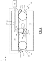
- the first proximity sensor 116 is located at a first distance 124 from the first surface 120
- the second proximity sensor 118 is located at a second distance 126 from the second surface 122.
- the second distance 126 is substantially equal. at the first distance 124 according to the present embodiment.
- the installation of the first and second proximity sensor 116, 118 is facilitated when the first distance 124 is equal to the second distance 126.
- the installation is quick and easy, because no distance measurement, for example of the difference of the first distance 124 relative to the second distance 126, for example in view of a calibration, is required.
- the first maximum detection range is different from the second maximum detection range.
- the difference between the first and the second maximum detection range is substantially equal to the difference between the first threshold and the second threshold of the separation.
- the difference is between 10mm and 30mm.
- the difference of the first relative to the second maximum detection range according to the second embodiment is substantially equal to the difference between the first distance 24 and the second distance 26 of the figure 1 .
- a method of checking the spacing 108 is implemented by the railway vehicle 100.
- the monitoring method is identical to the monitoring method implemented by the railway vehicle 1 of the first embodiment. The method is thus not described again.
- the first distance 24 and the second distance are different from each other.
- the first maximum detection range is different from the second maximum detection range.
Landscapes
- Engineering & Computer Science (AREA)
- Mechanical Engineering (AREA)
- Electric Propulsion And Braking For Vehicles (AREA)
- Vehicle Body Suspensions (AREA)
Applications Claiming Priority (1)
| Application Number | Priority Date | Filing Date | Title |
|---|---|---|---|
| FR2002792A FR3108300B1 (fr) | 2020-03-23 | 2020-03-23 | Véhicule ferroviaire et procédé associé |
Publications (2)
| Publication Number | Publication Date |
|---|---|
| EP3885231A1 true EP3885231A1 (de) | 2021-09-29 |
| EP3885231B1 EP3885231B1 (de) | 2023-01-25 |
Family
ID=70918630
Family Applications (1)
| Application Number | Title | Priority Date | Filing Date |
|---|---|---|---|
| EP21163907.5A Active EP3885231B1 (de) | 2020-03-23 | 2021-03-22 | Schienenfahrzeug und entsprechendes verfahren |
Country Status (4)
| Country | Link |
|---|---|
| EP (1) | EP3885231B1 (de) |
| ES (1) | ES2942218T3 (de) |
| FR (1) | FR3108300B1 (de) |
| PT (1) | PT3885231T (de) |
Citations (6)
| Publication number | Priority date | Publication date | Assignee | Title |
|---|---|---|---|---|
| JP2004182000A (ja) * | 2002-11-29 | 2004-07-02 | Sumitomo Metal Ind Ltd | 車体傾斜制御のフェールセーフ方法及び装置、鉄道車両並びにこの方法に使用する曲線判定方法 |
| JP2006231968A (ja) * | 2005-02-22 | 2006-09-07 | Nippon Sharyo Seizo Kaisha Ltd | 鉄道車両 |
| JP2007131125A (ja) * | 2005-11-10 | 2007-05-31 | Central Japan Railway Co | 車体傾斜装置の異常検出方法 |
| EP2692608A1 (de) * | 2011-03-31 | 2014-02-05 | Nippon Steel & Sumitomo Metal Corporation | Verfahren zur steuerung der karosserieneigung von eisenbahnwagen |
| EP3053803A1 (de) * | 2013-10-04 | 2016-08-10 | Nippon Steel & Sumitomo Metal Corporation | Fehlererkennungsverfahren für eine fahrzeugkarosserie-neigungssteuerungsvorrichtung |
| DE102016222663A1 (de) * | 2016-11-17 | 2018-05-17 | Contitech Luftfedersysteme Gmbh | Schienenfahrzeugfederung und Federsystem für ein Schienenfahrzeug |
-
2020
- 2020-03-23 FR FR2002792A patent/FR3108300B1/fr not_active Expired - Fee Related
-
2021
- 2021-03-22 EP EP21163907.5A patent/EP3885231B1/de active Active
- 2021-03-22 ES ES21163907T patent/ES2942218T3/es active Active
- 2021-03-22 PT PT211639075T patent/PT3885231T/pt unknown
Patent Citations (6)
| Publication number | Priority date | Publication date | Assignee | Title |
|---|---|---|---|---|
| JP2004182000A (ja) * | 2002-11-29 | 2004-07-02 | Sumitomo Metal Ind Ltd | 車体傾斜制御のフェールセーフ方法及び装置、鉄道車両並びにこの方法に使用する曲線判定方法 |
| JP2006231968A (ja) * | 2005-02-22 | 2006-09-07 | Nippon Sharyo Seizo Kaisha Ltd | 鉄道車両 |
| JP2007131125A (ja) * | 2005-11-10 | 2007-05-31 | Central Japan Railway Co | 車体傾斜装置の異常検出方法 |
| EP2692608A1 (de) * | 2011-03-31 | 2014-02-05 | Nippon Steel & Sumitomo Metal Corporation | Verfahren zur steuerung der karosserieneigung von eisenbahnwagen |
| EP3053803A1 (de) * | 2013-10-04 | 2016-08-10 | Nippon Steel & Sumitomo Metal Corporation | Fehlererkennungsverfahren für eine fahrzeugkarosserie-neigungssteuerungsvorrichtung |
| DE102016222663A1 (de) * | 2016-11-17 | 2018-05-17 | Contitech Luftfedersysteme Gmbh | Schienenfahrzeugfederung und Federsystem für ein Schienenfahrzeug |
Also Published As
| Publication number | Publication date |
|---|---|
| FR3108300A1 (fr) | 2021-09-24 |
| FR3108300B1 (fr) | 2022-04-01 |
| PT3885231T (pt) | 2023-04-14 |
| EP3885231B1 (de) | 2023-01-25 |
| ES2942218T3 (es) | 2023-05-30 |
Similar Documents
| Publication | Publication Date | Title |
|---|---|---|
| EP0461628B1 (de) | Schienenfahrzeug zum Messen von geometrischen Parametern des Gleises | |
| EP3792213A1 (de) | Pendelachse für eine hubmaschine, eine solche achse umfassende hubmaschine und steuerungsverfahren | |
| KR102424193B1 (ko) | 레일 검사 장치 및 레일 검사 시스템 | |
| EP3608195B1 (de) | Verfahren zur höhensteuerung eines fahrzeugs, und entsprechendes fahrzeug | |
| FR2683627A1 (fr) | Dispositif de mesure pour la mesure continue de denivellations ondulatoires d'un rail. | |
| EP0160591A1 (de) | Verfahren und Vorrichtung zur zerstörungsfreien Prüfung von Eisenbahnschienen | |
| EP0374395A2 (de) | Verfahren und Vorrichtung zur genauen Einstellung eines Teiles, das quer entlang einer Schiene versetzt ist | |
| EP0808758A1 (de) | Neigungsvorrichtung für Gelenkfahrzeuge,Zug bestehend aus Fahrzeugen und Fahrzeuge mit solch einer Vorrichtung | |
| EP3885231B1 (de) | Schienenfahrzeug und entsprechendes verfahren | |
| EP3241785A1 (de) | Bandförderer mit einer auswertevorrichtung der spannung des bandes | |
| EP3273214A1 (de) | Messverfahren des reifendrucks von reifen eines fahrzeugs in bewegung auf einer fahrspur | |
| CA2443588C (fr) | Procede et dispositif pour la localisation d`un rebord dispose a la jonction de deux surfaces globalement planes | |
| FR3017137A1 (fr) | Dispositif de mesure de l'etat d'une voie de circulation d'un vehicule guide | |
| EP2691780B1 (de) | Verfahren und system zur messung der geschwindigkeitsvariationen eines beweglichen körpers | |
| EP1676721A1 (de) | Eisenbahnrad und und solche Räder enthaltendes Eisenbahndrehgestell | |
| EP0439401A1 (de) | Scherenstromabnehmer mit gedämpfter Kopfaufhängung | |
| JP2013203094A (ja) | 検測車動揺状態補正方法及び装置、並びに検測方法及び装置 | |
| FR3010517A1 (fr) | Chariot de manutention | |
| FR3099724A1 (fr) | Véhicule ferroviaire comprenant un organe de réglage d’un système de suspension secondaire | |
| EP2316706A1 (de) | Wahrnehmungvorrichtung und Wahrnehmungsverfahren eines Bahnsteiges und Eisenbahnfahrzeug mit einer solchen Vorrichtung | |
| CH635283A5 (fr) | Dispositif de signalisation pour vehicules passant par des points fixes. | |
| JP5802560B2 (ja) | 検測車動揺補正方法及び装置、並びに検測方法及び装置 | |
| EP3403897B1 (de) | Befestigungsvorrichtung eines betätigungszylinders eines magnetischen gleitkörpers des drehgestells eines schienenfahrzeugs, entsprechendes drehgestell und entsprechendes schienenfahrzeug | |
| FR3141474A1 (fr) | Chariot de mesure pour une voie ferrée comprenant un dispositif de correction de dévers | |
| FR3025192A1 (fr) | Chariot de manutention comprenant au moins un galet d'appui |
Legal Events
| Date | Code | Title | Description |
|---|---|---|---|
| PUAI | Public reference made under article 153(3) epc to a published international application that has entered the european phase |
Free format text: ORIGINAL CODE: 0009012 |
|
| STAA | Information on the status of an ep patent application or granted ep patent |
Free format text: STATUS: THE APPLICATION HAS BEEN PUBLISHED |
|
| STAA | Information on the status of an ep patent application or granted ep patent |
Free format text: STATUS: REQUEST FOR EXAMINATION WAS MADE |
|
| AK | Designated contracting states |
Kind code of ref document: A1 Designated state(s): AL AT BE BG CH CY CZ DE DK EE ES FI FR GB GR HR HU IE IS IT LI LT LU LV MC MK MT NL NO PL PT RO RS SE SI SK SM TR |
|
| 17P | Request for examination filed |
Effective date: 20210913 |
|
| RBV | Designated contracting states (corrected) |
Designated state(s): AL AT BE BG CH CY CZ DE DK EE ES FI FR GB GR HR HU IE IS IT LI LT LU LV MC MK MT NL NO PL PT RO RS SE SI SK SM TR |
|
| GRAP | Despatch of communication of intention to grant a patent |
Free format text: ORIGINAL CODE: EPIDOSNIGR1 |
|
| STAA | Information on the status of an ep patent application or granted ep patent |
Free format text: STATUS: GRANT OF PATENT IS INTENDED |
|
| INTG | Intention to grant announced |
Effective date: 20220824 |
|
| GRAS | Grant fee paid |
Free format text: ORIGINAL CODE: EPIDOSNIGR3 |
|
| GRAA | (expected) grant |
Free format text: ORIGINAL CODE: 0009210 |
|
| STAA | Information on the status of an ep patent application or granted ep patent |
Free format text: STATUS: THE PATENT HAS BEEN GRANTED |
|
| AK | Designated contracting states |
Kind code of ref document: B1 Designated state(s): AL AT BE BG CH CY CZ DE DK EE ES FI FR GB GR HR HU IE IS IT LI LT LU LV MC MK MT NL NO PL PT RO RS SE SI SK SM TR |
|
| REG | Reference to a national code |
Ref country code: GB Ref legal event code: FG4D Free format text: NOT ENGLISH |
|
| RIN1 | Information on inventor provided before grant (corrected) |
Inventor name: NICOLEAU, GREGOIRE Inventor name: ESSOH, FABRICE |
|
| REG | Reference to a national code |
Ref country code: CH Ref legal event code: EP |
|
| REG | Reference to a national code |
Ref country code: AT Ref legal event code: REF Ref document number: 1545724 Country of ref document: AT Kind code of ref document: T Effective date: 20230215 Ref country code: IE Ref legal event code: FG4D Free format text: LANGUAGE OF EP DOCUMENT: FRENCH |
|
| REG | Reference to a national code |
Ref country code: DE Ref legal event code: R096 Ref document number: 602021001295 Country of ref document: DE |
|
| REG | Reference to a national code |
Ref country code: PT Ref legal event code: SC4A Ref document number: 3885231 Country of ref document: PT Date of ref document: 20230414 Kind code of ref document: T Free format text: AVAILABILITY OF NATIONAL TRANSLATION Effective date: 20230410 |
|
| REG | Reference to a national code |
Ref country code: LT Ref legal event code: MG9D |
|
| REG | Reference to a national code |
Ref country code: ES Ref legal event code: FG2A Ref document number: 2942218 Country of ref document: ES Kind code of ref document: T3 Effective date: 20230530 |
|
| REG | Reference to a national code |
Ref country code: NL Ref legal event code: MP Effective date: 20230125 |
|
| REG | Reference to a national code |
Ref country code: AT Ref legal event code: MK05 Ref document number: 1545724 Country of ref document: AT Kind code of ref document: T Effective date: 20230125 |
|
| PG25 | Lapsed in a contracting state [announced via postgrant information from national office to epo] |
Ref country code: NL Free format text: LAPSE BECAUSE OF FAILURE TO SUBMIT A TRANSLATION OF THE DESCRIPTION OR TO PAY THE FEE WITHIN THE PRESCRIBED TIME-LIMIT Effective date: 20230125 |
|
| PG25 | Lapsed in a contracting state [announced via postgrant information from national office to epo] |
Ref country code: RS Free format text: LAPSE BECAUSE OF FAILURE TO SUBMIT A TRANSLATION OF THE DESCRIPTION OR TO PAY THE FEE WITHIN THE PRESCRIBED TIME-LIMIT Effective date: 20230125 Ref country code: NO Free format text: LAPSE BECAUSE OF FAILURE TO SUBMIT A TRANSLATION OF THE DESCRIPTION OR TO PAY THE FEE WITHIN THE PRESCRIBED TIME-LIMIT Effective date: 20230425 Ref country code: LV Free format text: LAPSE BECAUSE OF FAILURE TO SUBMIT A TRANSLATION OF THE DESCRIPTION OR TO PAY THE FEE WITHIN THE PRESCRIBED TIME-LIMIT Effective date: 20230125 Ref country code: LT Free format text: LAPSE BECAUSE OF FAILURE TO SUBMIT A TRANSLATION OF THE DESCRIPTION OR TO PAY THE FEE WITHIN THE PRESCRIBED TIME-LIMIT Effective date: 20230125 Ref country code: HR Free format text: LAPSE BECAUSE OF FAILURE TO SUBMIT A TRANSLATION OF THE DESCRIPTION OR TO PAY THE FEE WITHIN THE PRESCRIBED TIME-LIMIT Effective date: 20230125 Ref country code: AT Free format text: LAPSE BECAUSE OF FAILURE TO SUBMIT A TRANSLATION OF THE DESCRIPTION OR TO PAY THE FEE WITHIN THE PRESCRIBED TIME-LIMIT Effective date: 20230125 |
|
| PG25 | Lapsed in a contracting state [announced via postgrant information from national office to epo] |
Ref country code: SE Free format text: LAPSE BECAUSE OF FAILURE TO SUBMIT A TRANSLATION OF THE DESCRIPTION OR TO PAY THE FEE WITHIN THE PRESCRIBED TIME-LIMIT Effective date: 20230125 Ref country code: PL Free format text: LAPSE BECAUSE OF FAILURE TO SUBMIT A TRANSLATION OF THE DESCRIPTION OR TO PAY THE FEE WITHIN THE PRESCRIBED TIME-LIMIT Effective date: 20230125 Ref country code: IS Free format text: LAPSE BECAUSE OF FAILURE TO SUBMIT A TRANSLATION OF THE DESCRIPTION OR TO PAY THE FEE WITHIN THE PRESCRIBED TIME-LIMIT Effective date: 20230525 Ref country code: GR Free format text: LAPSE BECAUSE OF FAILURE TO SUBMIT A TRANSLATION OF THE DESCRIPTION OR TO PAY THE FEE WITHIN THE PRESCRIBED TIME-LIMIT Effective date: 20230426 Ref country code: FI Free format text: LAPSE BECAUSE OF FAILURE TO SUBMIT A TRANSLATION OF THE DESCRIPTION OR TO PAY THE FEE WITHIN THE PRESCRIBED TIME-LIMIT Effective date: 20230125 |
|
| P01 | Opt-out of the competence of the unified patent court (upc) registered |
Effective date: 20230823 |
|
| RAP2 | Party data changed (patent owner data changed or rights of a patent transferred) |
Owner name: ALSTOM HOLDINGS |
|
| REG | Reference to a national code |
Ref country code: DE Ref legal event code: R097 Ref document number: 602021001295 Country of ref document: DE |
|
| PG25 | Lapsed in a contracting state [announced via postgrant information from national office to epo] |
Ref country code: SM Free format text: LAPSE BECAUSE OF FAILURE TO SUBMIT A TRANSLATION OF THE DESCRIPTION OR TO PAY THE FEE WITHIN THE PRESCRIBED TIME-LIMIT Effective date: 20230125 Ref country code: RO Free format text: LAPSE BECAUSE OF FAILURE TO SUBMIT A TRANSLATION OF THE DESCRIPTION OR TO PAY THE FEE WITHIN THE PRESCRIBED TIME-LIMIT Effective date: 20230125 Ref country code: MC Free format text: LAPSE BECAUSE OF FAILURE TO SUBMIT A TRANSLATION OF THE DESCRIPTION OR TO PAY THE FEE WITHIN THE PRESCRIBED TIME-LIMIT Effective date: 20230125 Ref country code: EE Free format text: LAPSE BECAUSE OF FAILURE TO SUBMIT A TRANSLATION OF THE DESCRIPTION OR TO PAY THE FEE WITHIN THE PRESCRIBED TIME-LIMIT Effective date: 20230125 Ref country code: DK Free format text: LAPSE BECAUSE OF FAILURE TO SUBMIT A TRANSLATION OF THE DESCRIPTION OR TO PAY THE FEE WITHIN THE PRESCRIBED TIME-LIMIT Effective date: 20230125 Ref country code: CZ Free format text: LAPSE BECAUSE OF FAILURE TO SUBMIT A TRANSLATION OF THE DESCRIPTION OR TO PAY THE FEE WITHIN THE PRESCRIBED TIME-LIMIT Effective date: 20230125 |
|
| PG25 | Lapsed in a contracting state [announced via postgrant information from national office to epo] |
Ref country code: SK Free format text: LAPSE BECAUSE OF FAILURE TO SUBMIT A TRANSLATION OF THE DESCRIPTION OR TO PAY THE FEE WITHIN THE PRESCRIBED TIME-LIMIT Effective date: 20230125 |
|
| PLBE | No opposition filed within time limit |
Free format text: ORIGINAL CODE: 0009261 |
|
| STAA | Information on the status of an ep patent application or granted ep patent |
Free format text: STATUS: NO OPPOSITION FILED WITHIN TIME LIMIT |
|
| PG25 | Lapsed in a contracting state [announced via postgrant information from national office to epo] |
Ref country code: LU Free format text: LAPSE BECAUSE OF NON-PAYMENT OF DUE FEES Effective date: 20230322 |
|
| 26N | No opposition filed |
Effective date: 20231026 |
|
| REG | Reference to a national code |
Ref country code: IE Ref legal event code: MM4A |
|
| PG25 | Lapsed in a contracting state [announced via postgrant information from national office to epo] |
Ref country code: SI Free format text: LAPSE BECAUSE OF FAILURE TO SUBMIT A TRANSLATION OF THE DESCRIPTION OR TO PAY THE FEE WITHIN THE PRESCRIBED TIME-LIMIT Effective date: 20230125 Ref country code: IE Free format text: LAPSE BECAUSE OF NON-PAYMENT OF DUE FEES Effective date: 20230322 |
|
| REG | Reference to a national code |
Ref country code: CH Ref legal event code: PL |
|
| PG25 | Lapsed in a contracting state [announced via postgrant information from national office to epo] |
Ref country code: BG Free format text: LAPSE BECAUSE OF FAILURE TO SUBMIT A TRANSLATION OF THE DESCRIPTION OR TO PAY THE FEE WITHIN THE PRESCRIBED TIME-LIMIT Effective date: 20230125 |
|
| PG25 | Lapsed in a contracting state [announced via postgrant information from national office to epo] |
Ref country code: BG Free format text: LAPSE BECAUSE OF FAILURE TO SUBMIT A TRANSLATION OF THE DESCRIPTION OR TO PAY THE FEE WITHIN THE PRESCRIBED TIME-LIMIT Effective date: 20230125 |
|
| PG25 | Lapsed in a contracting state [announced via postgrant information from national office to epo] |
Ref country code: CH Free format text: LAPSE BECAUSE OF NON-PAYMENT OF DUE FEES Effective date: 20240331 |
|
| REG | Reference to a national code |
Ref country code: GB Ref legal event code: 732E Free format text: REGISTERED BETWEEN 20250213 AND 20250219 |
|
| REG | Reference to a national code |
Ref country code: BE Ref legal event code: PD Owner name: ALSTOM HOLDINGS; FR Free format text: DETAILS ASSIGNMENT: CHANGE OF OWNER(S), ASSIGNMENT; FORMER OWNER NAME: ALSTOM TRANSPORT TECHNOLOGIES Effective date: 20241025 |
|
| PGFP | Annual fee paid to national office [announced via postgrant information from national office to epo] |
Ref country code: ES Payment date: 20250429 Year of fee payment: 5 |
|
| PG25 | Lapsed in a contracting state [announced via postgrant information from national office to epo] |
Ref country code: CY Free format text: LAPSE BECAUSE OF FAILURE TO SUBMIT A TRANSLATION OF THE DESCRIPTION OR TO PAY THE FEE WITHIN THE PRESCRIBED TIME-LIMIT; INVALID AB INITIO Effective date: 20210322 |
|
| PG25 | Lapsed in a contracting state [announced via postgrant information from national office to epo] |
Ref country code: HU Free format text: LAPSE BECAUSE OF FAILURE TO SUBMIT A TRANSLATION OF THE DESCRIPTION OR TO PAY THE FEE WITHIN THE PRESCRIBED TIME-LIMIT; INVALID AB INITIO Effective date: 20210322 |
|
| PG25 | Lapsed in a contracting state [announced via postgrant information from national office to epo] |
Ref country code: TR Free format text: LAPSE BECAUSE OF FAILURE TO SUBMIT A TRANSLATION OF THE DESCRIPTION OR TO PAY THE FEE WITHIN THE PRESCRIBED TIME-LIMIT Effective date: 20230125 |
|
| PGFP | Annual fee paid to national office [announced via postgrant information from national office to epo] |
Ref country code: GB Payment date: 20260324 Year of fee payment: 6 |
|
| PGFP | Annual fee paid to national office [announced via postgrant information from national office to epo] |
Ref country code: DE Payment date: 20260319 Year of fee payment: 6 |
|
| PGFP | Annual fee paid to national office [announced via postgrant information from national office to epo] |
Ref country code: BE Payment date: 20260319 Year of fee payment: 6 Ref country code: IT Payment date: 20260324 Year of fee payment: 6 |
|
| PGFP | Annual fee paid to national office [announced via postgrant information from national office to epo] |
Ref country code: FR Payment date: 20260323 Year of fee payment: 6 |
|
| PGFP | Annual fee paid to national office [announced via postgrant information from national office to epo] |
Ref country code: PT Payment date: 20260312 Year of fee payment: 6 |