EP3885256B1 - Energieabsorbierendes fahrwerkssystem für eine vorrichtung zum vertikalen landen und verfahren zur verwendung davon - Google Patents
Energieabsorbierendes fahrwerkssystem für eine vorrichtung zum vertikalen landen und verfahren zur verwendung davon Download PDFInfo
- Publication number
- EP3885256B1 EP3885256B1 EP21163934.9A EP21163934A EP3885256B1 EP 3885256 B1 EP3885256 B1 EP 3885256B1 EP 21163934 A EP21163934 A EP 21163934A EP 3885256 B1 EP3885256 B1 EP 3885256B1
- Authority
- EP
- European Patent Office
- Prior art keywords
- see
- landing
- assembly
- energy absorbing
- linear damper
- Prior art date
- Legal status (The legal status is an assumption and is not a legal conclusion. Google has not performed a legal analysis and makes no representation as to the accuracy of the status listed.)
- Active
Links
Images




Classifications
-
- B—PERFORMING OPERATIONS; TRANSPORTING
- B64—AIRCRAFT; AVIATION; COSMONAUTICS
- B64C—AEROPLANES; HELICOPTERS
- B64C25/00—Alighting gear
- B64C25/32—Alighting gear characterised by elements which contact the ground or similar surface
- B64C25/58—Arrangements or adaptations of shock-absorbers or springs
- B64C25/60—Oleo legs
-
- B—PERFORMING OPERATIONS; TRANSPORTING
- B64—AIRCRAFT; AVIATION; COSMONAUTICS
- B64C—AEROPLANES; HELICOPTERS
- B64C25/00—Alighting gear
- B64C25/32—Alighting gear characterised by elements which contact the ground or similar surface
- B64C25/58—Arrangements or adaptations of shock-absorbers or springs
-
- B—PERFORMING OPERATIONS; TRANSPORTING
- B64—AIRCRAFT; AVIATION; COSMONAUTICS
- B64D—EQUIPMENT FOR FITTING IN OR TO AIRCRAFT; FLIGHT SUITS; PARACHUTES; ARRANGEMENT OR MOUNTING OF POWER PLANTS OR PROPULSION TRANSMISSIONS IN AIRCRAFT
- B64D1/00—Dropping, ejecting, releasing or receiving articles, liquids, or the like, in flight
- B64D1/02—Dropping, ejecting, or releasing articles
- B64D1/08—Dropping, ejecting, or releasing articles the articles being load-carrying devices
- B64D1/14—Absorbing landing shocks
-
- F—MECHANICAL ENGINEERING; LIGHTING; HEATING; WEAPONS; BLASTING
- F16—ENGINEERING ELEMENTS AND UNITS; GENERAL MEASURES FOR PRODUCING AND MAINTAINING EFFECTIVE FUNCTIONING OF MACHINES OR INSTALLATIONS; THERMAL INSULATION IN GENERAL
- F16F—SPRINGS; SHOCK-ABSORBERS; MEANS FOR DAMPING VIBRATION
- F16F7/00—Vibration-dampers; Shock-absorbers
- F16F7/12—Vibration-dampers; Shock-absorbers using plastic deformation of members
- F16F7/121—Vibration-dampers; Shock-absorbers using plastic deformation of members the members having a cellular, e.g. honeycomb, structure
-
- F—MECHANICAL ENGINEERING; LIGHTING; HEATING; WEAPONS; BLASTING
- F16—ENGINEERING ELEMENTS AND UNITS; GENERAL MEASURES FOR PRODUCING AND MAINTAINING EFFECTIVE FUNCTIONING OF MACHINES OR INSTALLATIONS; THERMAL INSULATION IN GENERAL
- F16F—SPRINGS; SHOCK-ABSORBERS; MEANS FOR DAMPING VIBRATION
- F16F7/00—Vibration-dampers; Shock-absorbers
- F16F7/12—Vibration-dampers; Shock-absorbers using plastic deformation of members
- F16F7/125—Units with a telescopic-like action as one member moves into, or out of a second member
- F16F7/126—Units with a telescopic-like action as one member moves into, or out of a second member against the action of shear pins; one member having protuberances, e.g. dimples, ball bearings which cause the other member to deform
-
- B—PERFORMING OPERATIONS; TRANSPORTING
- B64—AIRCRAFT; AVIATION; COSMONAUTICS
- B64C—AEROPLANES; HELICOPTERS
- B64C25/00—Alighting gear
- B64C25/32—Alighting gear characterised by elements which contact the ground or similar surface
- B64C2025/325—Alighting gear characterised by elements which contact the ground or similar surface specially adapted for helicopters
-
- F—MECHANICAL ENGINEERING; LIGHTING; HEATING; WEAPONS; BLASTING
- F16—ENGINEERING ELEMENTS AND UNITS; GENERAL MEASURES FOR PRODUCING AND MAINTAINING EFFECTIVE FUNCTIONING OF MACHINES OR INSTALLATIONS; THERMAL INSULATION IN GENERAL
- F16F—SPRINGS; SHOCK-ABSORBERS; MEANS FOR DAMPING VIBRATION
- F16F2222/00—Special physical effects, e.g. nature of damping effects
- F16F2222/12—Fluid damping
-
- F—MECHANICAL ENGINEERING; LIGHTING; HEATING; WEAPONS; BLASTING
- F16—ENGINEERING ELEMENTS AND UNITS; GENERAL MEASURES FOR PRODUCING AND MAINTAINING EFFECTIVE FUNCTIONING OF MACHINES OR INSTALLATIONS; THERMAL INSULATION IN GENERAL
- F16F—SPRINGS; SHOCK-ABSORBERS; MEANS FOR DAMPING VIBRATION
- F16F9/00—Springs, vibration-dampers, shock-absorbers, or similarly-constructed movement-dampers using a fluid or the equivalent as damping medium
- F16F9/02—Springs, vibration-dampers, shock-absorbers, or similarly-constructed movement-dampers using a fluid or the equivalent as damping medium using gas only or vacuum
- F16F9/0209—Telescopic
- F16F9/0218—Mono-tubular units
-
- F—MECHANICAL ENGINEERING; LIGHTING; HEATING; WEAPONS; BLASTING
- F16—ENGINEERING ELEMENTS AND UNITS; GENERAL MEASURES FOR PRODUCING AND MAINTAINING EFFECTIVE FUNCTIONING OF MACHINES OR INSTALLATIONS; THERMAL INSULATION IN GENERAL
- F16F—SPRINGS; SHOCK-ABSORBERS; MEANS FOR DAMPING VIBRATION
- F16F9/00—Springs, vibration-dampers, shock-absorbers, or similarly-constructed movement-dampers using a fluid or the equivalent as damping medium
- F16F9/06—Springs, vibration-dampers, shock-absorbers, or similarly-constructed movement-dampers using a fluid or the equivalent as damping medium using both gas and liquid
- F16F9/061—Mono-tubular units
-
- F—MECHANICAL ENGINEERING; LIGHTING; HEATING; WEAPONS; BLASTING
- F16—ENGINEERING ELEMENTS AND UNITS; GENERAL MEASURES FOR PRODUCING AND MAINTAINING EFFECTIVE FUNCTIONING OF MACHINES OR INSTALLATIONS; THERMAL INSULATION IN GENERAL
- F16F—SPRINGS; SHOCK-ABSORBERS; MEANS FOR DAMPING VIBRATION
- F16F9/00—Springs, vibration-dampers, shock-absorbers, or similarly-constructed movement-dampers using a fluid or the equivalent as damping medium
- F16F9/10—Springs, vibration-dampers, shock-absorbers, or similarly-constructed movement-dampers using a fluid or the equivalent as damping medium using liquid only; using a fluid of which the nature is immaterial
- F16F9/14—Devices with one or more members, e.g. pistons, vanes, moving to and fro in chambers and using throttling effect
- F16F9/16—Devices with one or more members, e.g. pistons, vanes, moving to and fro in chambers and using throttling effect involving only straight-line movement of the effective parts
- F16F9/18—Devices with one or more members, e.g. pistons, vanes, moving to and fro in chambers and using throttling effect involving only straight-line movement of the effective parts with a closed cylinder and a piston separating two or more working spaces therein
- F16F9/19—Devices with one or more members, e.g. pistons, vanes, moving to and fro in chambers and using throttling effect involving only straight-line movement of the effective parts with a closed cylinder and a piston separating two or more working spaces therein with a single cylinder and of single-tube type
Definitions
- the disclosure relates generally to landing gear systems and methods for a vertical landing apparatus, and more particularly, to energy absorbing landing gear systems and methods for a vertical landing apparatus, such as a vertical landing aircraft.
- vertical landing apparatus such as vertical landing aircraft, for example, vertical take-off and landing (VTOL) aircraft, and electric and hybrid-electric vertical take-off and landing aircraft (eVTOLs), has grown in recent years, and such vertical landing aircraft are used in a variety of applications, including both civilian and military uses.
- VTOL vertical take-off and landing
- eVTOLs electric and hybrid-electric vertical take-off and landing aircraft
- Known landing gear systems used with such vertical landing aircraft may include oil-gas dampers or shock absorber systems mounted to the airframe of the vertical landing aircraft. The main purpose of such known landing gear systems is to absorb the impact energy resulting from a vertical landing motion.
- the buffering landing leg comprises an outer sleeve, an inner lining cylinder, a concave type cylinder, a rotating motor, a pushing rod, a floating piston, a piston cylinder, a gasket, a honeycomb-like buffering material, a spherical hinge, a foot pad and an end cover.
- the buffering landing leg is characterized by combining three buffering modes which are the oil buffering mode, the damping rubber buffering mode and the honeycomb-like buffering mode, and multi-level buffering can be conducted.
- a shock absorber comprising a strut, a sliding rod slidably mounted relative to the strut and co-operating therewith to define both a shock absorbing chamber and a raising chamber which is connected to a member for feeding it with raising liquid, a dip tube defining a lowering chamber and connected to a member for feeding it with a lowering liquid, and in which a lowering piston is disposed, which piston has one face in contact with the shock absorbing liquid, and an anti-crash tube mounted to slide relative to the sliding rod and including an energy-absorbing member.
- FR 3 062 112 according to its abstract states a landing gear for an aircraft comprising at least one device for landing equipped with a cushion and a system for limiting the friction effort.
- Said limiting system comprises a friction force energy absorption device capable of deforming in compression under the application of a force greater than a threshold of deformation, a support which is bonded said energy absorption device friction and a device arranged between said support and the said cushion.
- Said device friction generates a friction force so that said device energy absorption deforms when an effort in compression greater than a threshold of slip equal to the sum of said threshold of deformation and friction of said threshold is applied to said system for limiting the friction force causing a relative movement between said support and the said cushion.
- EP0 275 735 according to its abstract states a damper-jack that essentially comprises a rod in which a sliding piston delimits an outlet chamber, and which itself slides in a body by a piston delimiting a retraction chamber.
- the body contains a rolling device and, on the side opposite the rod, two gas chambers at low and high pressure. These two gas chambers are separated by a membrane resting, at rest, against a support with a perforated hemispherical bottom.
- the shock absorber-cylinder is provided with swivel end pieces and mounted in an elastic strut, bracing and maneuvering, a landing gear leg in balance whose shock-absorber cylinder allows the descent and the lifting in flight, as well as lifting and lowering on the ground.
- JP 2018 040120 according to its abstract states a damper system provided between two different structural members constituting a structure that are relatively displaced, and includes: a damper absorbing energy from relative displacement between a superstructure and a substructure; a fitting part fitted respectively on the superstructure and the substructure for supporting an edge part of the damper; an elastic member generating reactive force in response to relative displacement between the damper and the fitting part; a slit provided on either of an edge part or the fitting part; and a shaft provided on the other of the edge part or the fitting part, to be engaged with the slit.
- the slit includes a contact part coming in contact as the shaft is displaced along the slit.
- the elastic member is disposed between the shaft and the contact part.
- CN 106 986 006 A according to its abstract states a reusable angle-changing length-changing self-adaptation buffering landing mechanism comprising a landing leg, a ball hinge, a power device and a swing driving mechanism body which is matched with the power device to drive the landing leg to swing relative to the center of the ball hinge so as to change the angle;
- the landing leg comprises a leg main body and a rotary type magneto-rheological damper
- the leg main body comprises a main cylinder tube and a lead screw rod, wherein the main cylinder tube is matched with the ball hinge in the mode that the main cylinder tube can rotate around the axis of the main cylinder tube, the lead screw rod is sleeved with the main cylinder tube, the lead screw rod and the main cylinder tube form a lead screw nut pair so as to be used for changing the length, and the upper end of the main cylinder tube is in transmission connection with the rotary type magneto-rheological damper;
- the swing driving mechanism body comprises an arc-
- the load-initiating element is arranged in a load-transmitting manner in a recess, widened to an excessive degree in the load direction, of the basic body, and the fiber-composite web is arranged in a load-transmitting manner in the widened part of the recess and, at least at the web margins running in the load direction, has a fiber bond extending continuously into the adjacent marginal areas of the basic body and tearing open progressively in the event of overload.
- CN 206 900 639 U provides a damping landing gear of unmanned plane relates to VTOL formula unmanned aerial vehicle undercarriage field, including unmanned aerial vehicle frame and buffering undercarriage, the buffering undercarriage is connected in the unmanned aerial vehicle frame, the buffering undercarriage includes that cylinder type bounce cylinder and nestification are in but the sliding plunger foot rest in the bounce cylinder, be provided with the card cap that the antiskid is taken off on the piston foot rest, still be provided with tiny gas vent on the piston of piston foot rest.
- the utility model discloses set up current unmanned aerial vehicle undercarriage into complex bounce cylinder and piston foot rest, utilize ground reaction force to overcome the resistance acting, make the piston foot rest in compression, discharge when bounce cylinder is interior gaseous, eliminate the impact of ground reaction force to the unmanned aerial vehicle fuselage, realized the impact force when buffering unmanned aerial vehicle descends.
- the vertical landing aircraft makes a hard landing, for example, when it hits the ground at a vertical speed of greater than 2 m/s (two meters per second) and/or with a force greater than the vertical landing aircraft is designed to handle, such known landing gear systems mounted to the vertical landing aircraft, are not designed to absorb excess load due to the hard landing, and this may result in damage to the vertical landing aircraft. After the hard landing incident, the vertical landing aircraft may need to be temporarily or fully grounded until it can be proven that no damage to the vertical landing aircraft has occurred. This may be a time consuming and costly process.
- Example implementations of this disclosure provide energy absorbing landing gear systems and a method of using one or more energy absorbing landing gear systems on a vertical landing apparatus, to enhance an energy absorption capability during a landing phase.
- versions of the energy absorbing landing gear systems and method may provide significant advantages over existing systems and methods.
- an energy absorbing landing gear system for attachment to a vertical landing apparatus is an energy absorbing landing gear system according to claim 1.
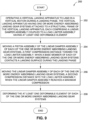
- a method of using one or more energy absorbing landing gear systems attached to a vertical landing apparatus during a landing phase of a vertical landing apparatus according to claim 12.
- the method may also comprise the step given by claims 13 and 14.
- “configured to” means various parts or components may be described or claimed as “configured to” perform a task or tasks.
- “configured to” is used to connote structure by indicating that the parts or components include structure that performs those task or tasks during operation. As such, the parts or components can be said to be configured to perform the task even when the specified part or component is not currently operational (e.g., is not on).
- first As used herein, the terms “first”, “second”, etc., are used as labels for nouns that they precede, and do not imply any type of ordering (e.g., spatial, temporal, logical, etc.).
- the term "or” is used as an inclusive or and not as an exclusive or.
- the phrase "at least one of x, y, or z” means any one of x, y, and z, as well as any combination thereof.
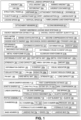
- FIG. 1 is an illustration of a functional block diagram showing exemplary versions of an energy absorbing landing gear system 10 of the disclosure, for attachment to a vertical landing apparatus 20.
- the blocks in FIG. 1 represent elements, and lines connecting the various blocks do not imply any particular dependency of the elements.
- the connecting lines shown in the various Figures contained herein are intended to represent example functional relationships and/or physical couplings between the various elements, but it is noted that other alternative or additional functional relationships or physical connections may be present in versions disclosed herein.
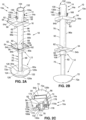
- FIGS. 2A-2C show one version of the energy absorbing landing gear system 10, such as in the form of energy absorbing landing gear system 10a.
- FIG. 2A is an illustration of a front perspective view of a version of the energy absorbing landing gear system 10, such as in the form of energy absorbing landing gear system 10a, of the disclosure.
- FIG. 2B is an illustration of a back perspective view of the energy absorbing landing gear system 10, such as in the form of energy absorbing landing gear system 10a, of FIG. 2A.
- FIG. 2C is an illustration of a top perspective view of the energy absorbing landing gear system 10, such as in the form of energy absorbing landing gear system 10a, of FIG. 2A .
- FIGS. 3A-3B show an exemplary version of an energy absorbing landing gear system 10, such as in the form of energy absorbing landing gear system 10b.
- FIG. 3A is an illustration of a front perspective view of another version of the energy absorbing landing gear system 10, such as in the form of energy absorbing landing gear system 10b.
- FIG. 3B is an illustration of a back perspective view of the energy absorbing landing gear system 10, such as in the form of energy absorbing landing gear system 10b, of FIG. 3A .
- the energy absorbing landing gear system 10 comprises a linear damper assembly 12 and a load limiter assembly 14.
- the load limiter assembly 14 is coupled or mounted to the linear damper assembly 12.
- the load limiter assembly 14 is coupled or mounted, in a series configuration 16 (see FIGS. 1 , 2A , 3A ), for example, a stacked series configuration, to the linear damper assembly 12.
- the load limiter assembly 14 is positioned atop, or over, the load limiter assembly 14, such as when the energy absorbing landing gear system 10 is in a vertical upright position 18 (see FIGS. 2A , 3A ) during landing.
- the energy absorbing landing gear system 10 is attached to, or is configured for attachment to, a vertical landing apparatus 20 (see FIGS. 1 , 7 , 8 ).
- the vertical landing apparatus 20 may have one, two, three, four, or more than four, energy absorbing landing gear systems 10 attached to, and/or installed in, the vertical landing apparatus 20.
- the vertical landing apparatus 20 has four energy absorbing landing gear systems 10 attached to, and installed in, the vertical landing apparatus 20.
- the energy absorbing landing gear systems 10 are in a vertical alignment 22 (see FIG. 8 ) with respect to each other.
- the vertical landing apparatus 20 may comprise an aircraft 20a, including a vertical take-off and landing (VTOL) aircraft 20b, a manned aircraft 20c, an unmanned aerial vehicle (UAV) 20d, a rotorcraft 20e, or another suitable type of aircraft.
- VTOL vertical take-off and landing
- UAV unmanned aerial vehicle
- rotorcraft 20e a rotorcraft 20e, or another suitable type of aircraft.
- VTOL vertical take-off and landing
- VTOL means an aircraft that can take off vertically and land vertically, and includes VTOL aircraft with powered rotors, VTOL aircraft with jet engines, electric VTOL (eVTOL) aircraft, and hybrid-electric VTOL aircraft.
- unmanned aircraft means an aircraft operated by a human pilot on board the aircraft
- unmanned aerial vehicle (UAV) means an aircraft operated without a human pilot on board the aircraft.
- the unmanned aerial vehicle (UAV) 20d may include a drone, a remote controlled aircraft, an unmanned aircraft system, an unmanned combat aerial vehicle, or another suitable UAV.
- the vertical landing apparatus 20 may further comprise an airdrop container 20f, such as an airdrop package or an airdrop vessel, configured to land vertically with one or more energy absorbing landing gear systems 10 attached.
- the vertical landing apparatus 20 comprises a structural frame 24 (see FIGS. 1 , 7 , 8 ), such as an airframe 24a (see FIGS. 1 , 7 , 8 ), or another suitable structural frame.
- Each energy absorbing landing gear system 10 is attached to, and/or installed in, the structural frame 24 of the vertical landing apparatus 20.
- the structural frame 24 may include one or more attachment portions 26 (see FIGS. 1 , 8 ), such as one or more booms 28 (see FIGS. 1 , 8 ), or other suitable attachment portions, for attachment or installation of the one or more energy absorbing landing gear systems 10 to the vertical landing apparatus 20.
- the energy absorbing landing gear systems 10 are attached to attachment portions 26, in the form of booms 28, of the structural frame 24 of the vertical landing apparatus 20.
- the vertical landing apparatus 20 takes off and flies, or is configured to take off and fly, during a flight phase 30 (see FIG. 1 ).
- the vertical landing apparatus 20 lands, or is configured to land, in a landing phase 32 (see FIG. 1 ), in a vertical landing motion 34 (see FIG. 1 ), on a landing surface 36 (see FIGS. 1 , 6B ), such as ground 36a (see FIGS. 1 , 6B ).
- the vertical landing apparatus 20 lands at a landing speed 38 (see FIG. 1 ), such as a vertical speed 40 (see FIG. 1 ), and upon landing, during the landing phase 32, the linear damper assembly 12 absorbs kinetic energy 42 (see FIG. 1 ) of the vertical landing apparatus 20.
- the linear damper assembly 12 can reach a load threshold 44 (see FIG. 1 ) in a hard-landing load condition 46 (see FIG. 1 ) during a hard landing of the vertical landing apparatus 20.
- hard-landing load condition means when a vertical landing apparatus hits a landing surface, such as the ground, with a vertical speed and a force that is greater than a force the vertical landing apparatus is designed to handle, for example, a vertical speed of greater than 2 m/s (two meters per second).
- the use of the one or more energy absorbing landing gear systems 10 with the vertical landing apparatus 20 enhances an energy absorption capability 48 (see FIG. 1 ) and an increase in an overall energy absorption quantity 50 (see FIG. 1 ) for energy absorption during landing, including a hard-landing load condition 46 during a hard landing.
- each of the one or more energy absorbing landing gear systems 10 is configured to be attached, and attaches, to the structural frame 24 of the vertical landing apparatus 20, via one or more attachment members 52.
- the one or more attachment members 52 may comprise one or more structural attachment fittings 54 (see FIGS. 1 , 2A-2C , 3A-3B ), attachment brackets, attachment couplings, or other suitable attachment members for attaching and securing the one or more energy absorbing landing gear systems 10 to the structural frame 24 of the vertical landing apparatus 20.
- Each attachment member 52 may be attached to the structural frame 24 of the vertical landing apparatus 20 with a means of attachment, such as by fastening with one or more fastening elements, for example, bolts, rivets, screws, or other suitable fastening elements, or by welding, or by adhesive bonding, or by another suitable means of attachment.
- a means of attachment such as by fastening with one or more fastening elements, for example, bolts, rivets, screws, or other suitable fastening elements, or by welding, or by adhesive bonding, or by another suitable means of attachment.
- the one or more attachment members 52 comprise two structural attachment fittings 54, such as in the form of a first structural attachment fitting 54a (see FIGS. 2A-2C , 3A-3B ), and a second structural attachment fitting 54b (see FIGS. 2A-2C , 3A-3B ).
- first structural attachment fitting 54a see FIGS. 2A-2C , 3A-3B
- second structural attachment fitting 54b see FIGS. 2A-2C , 3A-3B
- each structural attachment fitting 54 comprises a planar surface portion 56 (see FIGS. 2A, 2C , 3A ) having a through opening 58 (see FIGS.
- each structural attachment fitting 54 further comprises one or more sides 62 (see FIGS. 2A-2C , 3A-3B ) extending from the planar surface portion 56, for example, one or more sides 62 extending substantially perpendicular to the planar surface portion 56.
- each structural attachment fitting 54 has four sides 62.
- each structural attachment fitting 54 may have less than four sides or more than four sides, depending on the chosen shape and configuration of the structural attachment fitting used.
- At least one of the one or more sides 62 of the structural attachment fitting 54 is configured to be attached or secured, and attaches or secures, to the structural frame 24 (see FIGS. 1 , 7 ) of the vertical landing apparatus 20 (see FIGS. 1 , 7 ).
- another portion or portions of the attachment member 52, such as the structural attachment fitting 54 may be attached, or secured, to the structural frame 24 of the vertical landing apparatus 20.
- the one or more attachment members 52 may also be used with one or more sliding bearings 64 (see FIGS. 1 , 4A , 5A-5C ).
- the one or more sliding bearings 64 are preferably disposed or positioned in a space 66 (see FIGS. 5B-5C ) between, and in contact with, one or more interior portions 68 (see FIGS. 5B-5C ) of each of the one or more attachment members 52 (see FIGS. 5B-5C ), such as each of the one or more structural attachment fittings 54 (see FIGS. 5B-5C ), and in contact with the one or more exterior portions 60 (see FIGS.
- the one or more sliding bearings 64 preferably comprise one or more low friction sliding bearings positioned in the space 66 between the attachment member 52, such as the structural attachment fitting 54, and the linear damper assembly 12.
- each energy absorbing landing gear system 10 comprises the linear damper assembly 12.
- the linear damper assembly 12 comprises a linear damper 70 (see FIGS. 2A-2B , 3A-3B ) coupled to a base member 72 (see FIGS. 2A-2C , 3A-3B ).
- the linear damper 70 comprises one of, an oil-gas damper 70a, a gas spring 70b, a hydraulic shock absorber 70c, an elastic damper 70d, or another suitable linear damper.
- linear damper means a mechanical or hydraulic device designed to absorb and damp shock impacts, by converting kinetic energy of the shock impact into another form of energy, such as deformation energy or heat.
- the linear damper 70 may also be referred to as a linear shock absorber.
- the linear damper 70 comprises at least a piston assembly 74 (see FIGS. 1 , 2A , 3A-3B ), a cylinder assembly 76 (see FIGS. 1 , 2A-2B , 3A-3B ) coupled to the piston assembly 74, and a cap element 78 (see FIGS. 1 , 4A , 5A ) coupled to, and atop, the cylinder assembly 76.
- a piston assembly 74 see FIGS. 1 , 2A , 3A-3B
- a cylinder assembly 76 see FIGS. 1 , 2A-2B , 3A-3B
- cap element 78 see FIGS. 1 , 4A , 5A
- the piston assembly 74 of the linear damper 70 comprises a first end 80a and a second end 80b, and comprises a piston rod 82 having a first end 84a, a second end 84b, and a body 86 formed between the first end 84a and the second end 84b.
- the first end 84a of the piston rod 82 is coupled, or attached, to the base member 72 (see FIGS. 2A , 3A ).
- the piston assembly 74 further comprises a piston 88 having a first end face 90a and a second end face 90b.
- the first end face 90a of the piston 88 is coupled, or attached, to the second end 84b of the piston rod 82.
- the second end face 90b of the piston 88 is configured to interact, and interacts, with the cap element 78 (see FIGS. 4A , 5A ).
- the piston 88 may be in the form of a disk, a cylinder, or another suitable form or configuration.
- the piston 88 and the piston rod 82 are preferably made of a metal material, such as aluminum, aluminum alloy, or another suitable metal material.
- the piston rod 82 is configured to translate or move, and translates or moves, in and out of the cylinder assembly 76, and the piston rod 82 is configured to move, and moves, the piston 88 up and down within the cylinder assembly 76.
- the piston assembly 74 may further comprise one or more of, valves, valve shims, ports, seals including O-rings, or other piston assembly components known in the art.
- the cylinder assembly 76 of the linear damper 70 comprises a cylinder 92, such as a shock cylinder.
- the cylinder 92 has a first end 94a (see FIGS. 2B , 3B ), a second end 94b (see FIGS. 2B , 3B ), an exterior 96a (see FIGS. 2A-2B , 3A-3B ), an interior 96b (see FIGS. 2A , 3A ), and one or more chambers 98 (see FIGS. 1 , 2A , 3A ) disposed in the interior 96b.
- the linear damper 70 comprises an oil-gas damper 70a (see FIG.
- the chambers 98 comprise an oil chamber 98a (see FIG. 1 ) filled with an oil 100 (see FIG. 1 ), for example, silicone oil, and a gas chamber 98b (see FIG. 1 ) filled with a pressurized gas 102 (see FIG. 1 ), or compressed gas, for example, nitrogen gas.
- the linear damper 70 comprises a gas spring 70b (see FIG. 1 )
- the chamber 98 comprises the gas chamber 98b filled with the pressurized gas 102, or compressed gas, for example, nitrogen gas.
- the gas spring 70b uses pressurized gas 102, or compressed gas, contained within the gas chamber 98b of the cylinder 92 sealed by the piston 88 that translates, or moves, up and down within the cylinder 92, to pneumatically store potential kinetic energy and withstand external force applied parallel to the direction of the piston rod 82.
- the linear damper 70 comprises a hydraulic shock absorber 70c (see FIG. 1 )
- the chamber 98 comprises a hydraulic fluid chamber 98c (see FIG. 1 ) filled with a hydraulic fluid 104 (see FIG. 1 ).
- the cylinder 92 houses the piston 88 and the second end 84b of the piston rod 82 in the interior 96b of the cylinder 92.
- the first end 94a (see FIGS. 2B , 3B ) of the cylinder 92 has an opening 106 (see FIGS. 2B , 3B ) configured to receive, and receiving, substantially the piston rod 82, when the piston rod 82 translates, or moves, into the interior 96b of the cylinder 92, during the landing phase 32 of the vertical landing apparatus 20.
- first compression distance means a distance that the piston assembly 74, including the piston rod 82 and the piston 88, moves and compresses upwardly into the interior 96b of the cylinder 92 of the cylinder assembly 76 toward the load limiter assembly 14.
- the cylinder 92 is preferably made of a metal material, such as aluminum, aluminum alloy, stainless steel, or another suitable metal material.
- the cylinder assembly 76 may further comprise a sleeve 108 (see FIG. 1 ), for example, a carbon tube sleeve, surrounding or enclosing a portion, or all of, the exterior 96a of the cylinder 92.
- the cylinder assembly 76 may further comprise one or more of, valves, valve shims, ports, seals including O-rings, or other cylinder assembly components known in the art.
- the cap element 78 (see FIGS. 1 , 4A , 5A , 6A ) of the linear damper 70 (see FIGS. 1 , 6A ) is attached to, or mounted on, the second end 94b (see FIGS. 4A , 5A-5B ) of the cylinder 92.
- the cap element 78 of the linear damper 70 comprises a first end 110a, a second end 110b, and a body 112 formed between the first end 110a and the second end 110b.
- the second end 110b of the cap element 78 comprises a curved portion 114 with a through opening 116.
- the second end 110b of the cap element 78 comprises a flat surface interface 118.
- the first end 110a of the cap element 78 is configured to interface, and interfaces, with the second end 94b of the cylinder 92, and the first end 110a of the cap element 78 is also configured to interface, and interfaces, with the second end 80b (see FIGS. 2A , 3A ) of the piston assembly 74 (see FIGS. 2A , 3A ), for example, the second end face 90b (see FIGS.
- the first end 110a of the cap element 78 may also be configured to interface, and interfaces, with a top portion of the sleeve 108.
- the cap element 78 (see FIGS. 4A , 5A ) is coupled to, and positioned within, the load limiter assembly 14.
- the base member 72 comprises one of, a landing pad 72a, a wheel 72b, a landing skid 72c, or another suitable base member.
- the base member 72 comprises a landing pad 72a having a bottom end 120a, a top end 120b, a body 122 formed between the bottom end 120a and the top end 120b, an exterior 124, and an interior 126.
- a central hole 128 is formed through the top end 120b into the interior 126 of the base member 72. The central hole 128 is configured to receive, and receives, the first end 80a (see FIGS.
- the bottom end 120a (see FIGS. 2A , 3A , 6B ) of the base member 72 of the energy absorbing landing gear system 10 is configured to interface, and interfaces, with the landing surface 36 (see FIG. 6B ), such as the ground 36a (see FIG. 6B ), during the landing phase 32 (see FIGS. 1 , 6B ) of the vertical landing apparatus 20 (see FIG. 1 ).
- the energy absorbing landing gear system 10 further comprises the load limiter assembly 14 (see FIGS. 1 , 2A-2C , 3A-3B ).
- the load limiter assembly 14 is coupled to the cylinder 92 (see FIGS. 2A , 3A ).
- the load limiter assembly 14 is coupled in the series configuration 16 (see FIGS. 1 , 2A , 3A ) to the cylinder 92 (see FIGS. 2A , 3A ) of the linear damper assembly 12 (see FIGS. 1 , 2A , 3A ).
- the load limiter assembly 14 is attached to, or integrated into, the attachment member 52, such as the structural attachment fitting 54, for example, the first structural attachment fitting 54a.
- the load limiter assembly 14 comprises at least one deformable element 130 (see FIGS. 1 , 2A-2B , 4A , 5A ), to enhance the energy absorption capability 48 (see FIG. 1 ).
- the load limiter assembly 14 further comprises a tubular fitting 132 (see FIGS. 1 , 2A-2B , 3A-3B , 4A , 5A-5C ) incorporating the at least one deformable element 130, or housing the at least one deformable element 130, or otherwise coupled to, the at least one deformable element 130.
- FIGS. 1 , 2A-2C , 4A show one version of the load limiter assembly 14, such as in the form of a first load limiter assembly 14a.
- FIGS. 1 , 3A-3B , 5A-5B show another example of the load limiter assembly 14, such as in the form of a second load limiter assembly 14b.
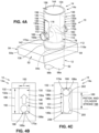
- FIGS. 4A-4C show in further detail the load limiter assembly 14, such as in the form of the load limiter assembly 14a.
- FIG. 4A is an illustration of a front perspective view of a version of the load limiter assembly 14, such as in the form of the first load limiter assembly 14a, that may be used in a version of the energy absorbing landing gear system 10 of the disclosure.
- the load limiter assembly 14, such as in the form of the load limiter assembly 14a comprises the tubular fitting 132, such as in the form of an open tubular fitting 132a, having an open top 134 (see also FIG. 2A ).
- FIG. 2A shows an open top 134 (see also FIG. 2A ).
- the tubular fitting 132 such as the open tubular fitting 132a, has a first end 136, a second end 138, a tubular body 140 formed between the first end 136 and the second end 138, an exterior 142, and an interior 144.
- the interior 144 of the tubular fitting 132 is open or hollow, and when the load limiter assembly 14 is coupled, or attached, to the linear damper assembly 12, the tubular fitting 132 is configured to receive and house, and receives and houses, the cap element 78 (see FIG. 4A ) of the linear damper assembly 12.
- the interior 144 of the tubular fitting 132 is further configured to receive, and receives, the second end 80b (see FIG. 2A ) of the piston assembly 74 (see FIG.
- the tubular fitting 132 incorporates the at least one deformable element 130 formed in and/or on the tubular body 140.
- the at least one deformable element 130 comprises two deformable elements 130a (see FIGS. 2A , 4A ), 130b (see FIGS. 2B , 4A ), formed in and on the tubular body 140, and aligned opposite each other on the tubular body 140 of the tubular fitting 132.
- Each of the two deformable elements 130a, 130b may be in the form of a machined feature 148 (see FIGS. 1 , 4A-4B ), for example, a machined vertical rectangle, or another suitable machined feature shape.
- the two deformable elements 130a, 130b are preferably the same shape and size, and each deformable element 130, such as the machined feature 148, has a length 150 (see FIG. 4B ), a width 152 (see FIG. 4B ), and a thickness 154 (see FIG. 4A ). It is preferable to have the length 150 of the deformable element 130 be sufficiently long so as to maximize the amount of energy absorbed by the deformable element 130 and to provide a longest possible deformation length. The length 150 and geometry of the deformable element 130 is determined and balanced against a desired weight of the energy absorbing landing gear system 10.
- each deformable element 130a, 130b is less than, or thinner than, a thickness 156 (see FIG. 4A ) of a remaining portion 158 (see FIG. 4A ) of the tubular body 140 (see FIG. 4A ) that does not comprise the two deformable elements 130a, 130b.
- a thickness 156 see FIG. 4A
- a remaining portion 158 see FIG. 4A
- the tubular body 140 see FIG. 4A
- each of the two deformable elements 130a, 130b have a through opening 160 formed through a portion of each of the two deformable elements 130a, 130b.
- the at least one deformable element 130 is preferably made of a deformable element material 162 (see FIG. 1 ) having a strength 164 (see FIG. 1 ) and a load capacity 166 (see FIG. 1 ).
- the deformable element material 162 comprises a soft metal material 162a (see FIG. 1 ), that is easily deformable and cut, for example, aluminum, copper, or another suitably soft metal material.
- the remaining portion 158 of the tubular body 140 that does not comprise the two deformable elements 130a, 130b, is preferably made of the same soft metal material 162a as the deformable element material 162, for example, aluminum, copper, or another suitably soft metal material, except that the thickness 156 of the remaining portion 158 of the tubular body 140 is greater than the thickness 154 of each of the two deformable elements 130a, 130b, which are preferably machined to be made thinner.
- the load limiter assembly 14 such as in the form of the load limiter assembly 14a, further comprises a pin 168 configured for insertion, and inserted, through each through opening 160 of the two deformable elements 130a, 130b.
- the pin 168 is also configured for insertion, and inserted, through the through opening 116 of the cap element 78, so that that pin 168 is coupled to the two deformable elements 130a, 130b of the tubular fitting 132, and is further coupled to the cap element 78 of the linear damper assembly 12.
- the pin 168 may comprise a shear pin 168a (see FIGS. 2A-2B , 4A-4C ), or another suitable type of pin.
- a bolt, a rod, or another suitable cylindrical mechanical element that is configured for insertion, and inserted, through each through opening 160 of the two deformable elements 130a, 130b, and through the through opening 116 of the cap element 78, may be used.
- the pin 168 such as in the form of the shear pin 168a, is designed to shear, or tear, through the two deformable elements 130a, 130b.
- the pin 168 such as the shear pin 168a, comprises a head end 170a, a tail end 170b, and a cylindrical shaft 172 formed between the head end 170a and the tail end 170b.
- the cylindrical shaft 172 has an exterior 174 (see FIG. 2C ) and a diameter 176 (see FIG. 2C ).
- the cylindrical shaft 172 of the pin 168 is inserted through the through opening 160 of the deformable element 130a, is then inserted through the through opening 116 of the cap element 78, and is then inserted through the through opening 160 of the deformable element 130b.
- a retaining element 178 may optionally be coupled or attached to the tail end 170b (see FIG. 2C ) of the pin 168 (see FIG. 2C ), if desired, to further facilitate retaining or securing the pin 168 in place.
- the retaining element 178 may be in the form of a cotter pin, a clip, or another suitable retaining element.
- the pin 168 such as the shear pin 168a, is made of a pin material 180 (see FIG. 1 ) having a strength 182 (see FIG. 1 ) and a load capacity 184 (see FIG. 1 ).
- the pin material 180 (see FIG. 1 ) comprises a hard metal material 180a (see FIG. 1 ), for example, steel, stainless steel, titanium, or another suitably hard metal material.
- the strength 182 of the pin material 180 forming the pin 168, such as the shear pin 168a, is greater than the strength 164 of the deformable element material 162 forming the at least one deformable element 130, such as the two deformable elements 130a, 130b.
- the load capacity 184 of the pin material 180 forming the pin 168 is greater than the load capacity 166 of the deformable element material 162 forming the at least one deformable element 130, such as the two deformable elements 130a, 130b.
- the pin material 180 selected to form the pin 168, such as the shear pin 168a has a strength 182 sufficient to tear through the deformable element material 162 forming the at least one deformable element 130, such as the two deformable elements 130a, 130b, without the pin 168, such as the shear pin 168a, breaking.
- the pin material 180 selected to form the pin 168 is preferably resistant to fatigue, and when subjected to small forces insufficient to break the pin 168, the pin 168 is not damaged.
- the strength and load capacity of the material or materials forming each of the bolt, rod, or other suitable cylindrical mechanical element is greater than the strength 164 and the load capacity 166 of the deformable element material 162 forming the at least one deformable element 130, such as the two deformable elements 130a, 130b.
- FIG. 4B is an illustration of a left side view of the load limiter assembly 14, such as the load limiter assembly 14a, of FIG. 4A , where the deformable element 130, such as deformable element 130a, for example, in the form of machined feature 148, is in an undeformed position 186a.
- FIG. 4B further shows the head end 170a of the pin 168, such as the shear pin 168a, and shows the pin 168, such as the shear pin 168a, in a start position 188a.
- the linear damper assembly 12 absorbs kinetic energy 42 (see FIG. 1 ) from the vertical landing motion 34 (see FIG.
- the linear damper assembly 12 moves a second compression distance 189 (see FIGS. 1 , 4C , 5C , 6B ) upwardly into the load limiter assembly 14, and the at least one deformable element 130, such as the two deformable elements 130a, 130b, deform.
- second compression distance means a distance that the linear damper assembly 12, including the piston assembly 74 and the cylinder assembly 76, moves and compresses upwardly into the load limiter assembly 14, for example, into the interior 144 (see FIG. 4A ) of the tubular fitting 132, such as the open tubular fitting 132a (see FIG. 4A ), of the load limiter assembly 14, such as the first load limiter assembly (see FIG. 4A ), or into an interior 144a (see FIG. 5A ) of the tubular fitting 132, such as a closed tubular fitting 132b (see FIG. 5A ), of the load limiter assembly 14, such as an exemplary load limiter assembly (see FIG. 5A ).
- an excess kinetic energy 42a causes the linear damper assembly 12, for example, the piston assembly 74 (see FIG. 2A ) and the cylinder assembly 76 (see FIG. 2A ), of the linear damper assembly 12, to translate, or move, into the load limiter assembly 14, and the at least one deformable element 130, such as the two deformable elements 130a, 130b, absorb the excess kinetic energy 42a and deform.
- the two deformable elements 130a, 130b absorb the excess kinetic energy 42a and irreversibly deform.
- the pin 168 such as the shear pin 168a, tears, or wedges, through the deformable element 130a in an upward direction 190 (see FIG. 4B ).
- FIG. 4C is an illustration of a left side view of the load limiter assembly 14, such as the load limiter assembly 14a, of FIG. 4A , where a deformed element 131, such as a deformed element 131a, for example, in the form of a deformed machined feature 148a, is in a deformed position 186b.
- FIG. 4C further shows the head end 170a of the pin 168, such as the shear pin 168a, and shows the pin 168, such as the shear pin 168a, in an end position 188b.
- the kinetic energy 42 of the linear damper assembly 12 is transformed into a deformation energy 192 (see FIG.
- the deformable elements 130a, 130b such as in the form of machined features 148, in the tubular fitting 132, guide the pin 168, such as the shear pin 168a, vertically as it tears through the deformable elements 130a, 130b. to form and obtain the deformed elements 131a, 131b (see FIG. 1 ).
- the pin 168 such as the shear pin 168a, follows the direction of least resistance, such as where the material wall thickness is thinnest, for example, the thickness 154 (see FIG. 4A ) of the deformable elements 130a, 130b (see FIG. 4A ).
- the thickness 154 of the deformable elements 130a, 130b of the tubular body 140 of the tubular fitting 132 determines a shear-through force 194 (see FIG. 1 ) of the pin 168, such as the shear pin 168a.
- FIG. 4C shows a piston and cylinder stroke 198 of the linear damper assembly 12 (see FIG. 1 ) that has moved the second compression distance 189. It is preferable to have the length 150 of each of the deformable elements 130a, 130b, be sufficiently long so as to maximize the amount of energy absorbed by the deformable elements 130a, 130b, and to provide a longest possible deformation length.
- the length 150 and geometry of each of the deformable elements 130a, 130b is determined and balanced against a desired weight of the energy absorbing landing gear system 10. By measuring a distance of the additional stroke of the piston and cylinder stroke 198, it is possible to determine the excess kinetic energy 42a (see FIG. 1 ), or additional energy, absorbed by the load limiter assembly 14 and the energy absorbing landing gear system 10.
- the pin 168 such as the shear pin 168a
- the pin 168 has torn through the deformable element 130a (see FIG. 4B ) of the tubular fitting 132, to form a torn slot portion 200, which results in obtaining the deformed element 131, such as the two deformed elements 131a, 131b (see FIGS. 1 , 4C ) having a deformation 201 (see FIG. 1 ).
- the two deformed elements 131a, 131b irreversibly deform and have an irreversible deformation 202 (see FIGS. 1 , 4C ), or permanent deformation.
- the at least one deformable element 130 for example, the two deformable elements 130a, 130b, each function as a load fuse and a secondary energy absorber, to result in the at least one deformed element 131, for example, the two deformed elements 131a, 131b.
- the deformable elements 130a, 130b in the undeformed position 186a (see FIG. 4B ) may function, or serve, as mechanical sacrificial parts that may irreversibly or permanently deform to obtain the deformed elements 131a, 131b (see FIGS. 1 , 4C ) in the deformed position 186b (see FIG.
- the at least one deformed element 131 such as the two deformed elements 131a, 131b, of the load limiter assembly 14, such as the first load limiter assembly 14a, may serve, or function, as a mechanical shock absorber 206 (see FIG. 1 ) based on an irreversible deformation energy 192a (see FIG. 1 ).
- the at least one deformed element 131 such as deformed elements 131a, 131b, serve, or function, as a visual indicator 208 (see FIGS. 1 , 4C ) that a load threshold 44 (see FIG. 1 ) of the linear damper assembly 12 (see FIG. 1 ) was exceeded, and that the energy absorbing landing gear system 10 (see FIG. 1 ) is overloaded or has absorbed additional load, which is more than it was designed to handle, such as due to a hard-landing load condition 46 (see FIG. 1 ) during a hard landing of the vertical landing apparatus 20 (see FIG. 1 ), and is the visual indicator 208 that the vertical landing apparatus 20 experienced a hard landing.
- the at least one deformed element 131 such as deformed elements 131a, 131b, serve, or function, as the visual indicator 208 (see FIGS. 1 , 4C ) that an amount 201a (see FIG. 1 ) of the deformation 201 (see FIG. 1 ), or an amount 202a (see FIG. 1 ) of the irreversible deformation 202 (see FIGS. 1 , 4C ), shows an extent 44a (see FIG. 1 ) to which the load threshold 44 (see FIG. 1 ) of the linear damper assembly 12 (see FIG. 1 ) and the energy absorbing landing gear system 10 (see FIG. 1 ) were exceeded.
- an indicator or a reference line on the cylinder 92 of the linear damper 70 may be used to visually indicate or show whether the cylinder 92 has moved or not.
- Such indicator or reference line may comprise a marking, a sticker, or another suitable indicator.
- the at least one deformed element 131 such as deformed elements 131a, 131b, serve, or function, as the visual indicator 208 (see FIGS. 1 , 4C ) that there was movement of the pin 168, such as the shear pin 168a (see FIGS. 4A-4C ), which shows that the vertical landing apparatus 20 (see FIG. 1 ) made a hard landing.
- the load limiter assembly 14, such as the load limiter assembly 14a, with the tubular fitting 132 having the at least one deformed element 131, such as the two deformed elements 131a, 131b, that are deformed, or irreversibly deformed, may be inspected and replaced or exchanged with a load limiter assembly 14, such as the load limiter assembly 14a, with the tubular fitting 132 having the at least one deformable element 130, such as the two deformed elements 130a, 130b, that are not damaged or irreversibly deformed.
- FIGS. 5A-5D show in further detail the load limiter assembly 14, such as in the form of the exemplary load limiter assembly 14b.
- FIG. 5A is an illustration of a front perspective view of the load limiter assembly 14, such as in the form of the exemplary load limiter assembly 14b, used in the energy absorbing landing gear system 10 of the disclosure, where the load limiter assembly 14, such as in the form of the exemplary load limiter assembly 14b, comprises a tubular fitting 132, such as a closed tubular fitting 132b, and at least one deformable element 130.
- the load limiter assembly 14 such as in the form of the exemplary load limiter assembly 14b, comprises the tubular fitting 132, such as in the form of the closed tubular fitting 132b, having a closed top 135.
- the tubular fitting 132 such as the closed tubular fitting 132b, has a first end 136a, a second end 138a, a tubular body 140a formed between the first end 136a and the second end 138a, an exterior 142a, and an interior 144a.
- the interior 144a see FIGS.
- the tubular body 140a of the tubular fitting 132 such as the closed tubular fitting 132b, is open or hollow, and is configured to receive and house, and receives and houses, at least one deformable element 130 (see FIGS. 5A-5B ).
- the interior 144a of the tubular body 140a of the tubular fitting 132 is configured to receive and house, and receives and houses, the cap element 78 (see FIGS. 5A-5C ) of the linear damper assembly 12 (see FIGS. 5A-5C ).
- the linear damper assembly 12 reaches the maximum compression 146 (see FIG.
- the excess kinetic energy 42a causes the linear damper assembly 12 to translate, or move, such as translate, or move, upwardly, into the load limiter assembly 14, during the landing phase 32 of the vertical landing apparatus 20, the interior 144a of the tubular body 140a of the tubular fitting 132, such as the closed tubular fitting 132b, is further configured to receive, and receives, at least the second end 94b (see FIG. 5C ) of the cylinder 92 (see FIG. 5C ) of the linear damper assembly 12 (see FIG. 5C ).
- the at least one deformable element 130 comprises one deformable element 130 disposed, or housed, in the interior 144a of the tubular body 140a of the tubular fitting 132, such as the closed tubular fitting 132b, and the deformable element 130 is mounted atop the linear damper assembly 12, and in particular, is mounted atop the cap element 78, which is mounted atop the cylinder 92 of the linear damper 70 of the linear damper assembly 12.
- the deformable element 130 comprises in an exemplary version, a deformable crush element 210.
- the deformable crush element 210 see FIGS.
- metal honeycomb crush element 210a preferably comprises a metal honeycomb crush element 210a (see FIG. 1 ), for example, an aluminum honeycomb crush element 210b (see FIGS. 1 , 5A-5B ), or another suitable deformable crush element.
- Metal honeycomb crush elements 210a such as aluminum honeycomb crush elements 210b, are particularly suitable because they have a very low mass density, e.g., 16-150 kg/m 3 and may be compressed to 80% of their initial length.
- two or more deformable elements 130 such as two or more deformable crush elements 210, may be stacked on each other, or otherwise coupled together, and disposed, or housed in the interior 144a of the tubular body 140a of the tubular fitting 132, such as the closed tubular fitting 132b.
- the deformable element 130 such as the deformable crush element 210, for example, the metal honeycomb crush element 210a, preferably in the form of the aluminum honeycomb crush element 210b, is made of a deformable element material 162 (see FIG. 1 ) having a strength 164 (see FIG. 1 ) and a load capacity 166 (see FIG. 1 ).
- the deformable element material 162 (see FIG. 1 ) comprises a metal honeycomb material 162b (see FIG. 1 ), such as an aluminum honeycomb material, or another suitable metal honeycomb material.
- the length of each of the deformable element 130 is sufficiently long so as to maximize the amount of energy absorbed by the deformable element 130, and to provide a longest possible deformation or crush length.
- the length and geometry of the deformable element is determined and balanced against a desired weight of the energy absorbing landing gear system 10.
- the deformable element 130 such as the deformable crush element 210, for example, the aluminum honeycomb crush element 210b, comprises a first end 212a, a second end 212b, and a body 214 disposed between the first end 212a and the second end 212b.
- the first end 212a of the deformable crush element 210 preferably interfaces with the flat surface interface 118 (see FIGS. 5A-5B ) of the cap element 78 (see FIGS. 5A-5B ), and the second end 212b preferably interfaces with the interior of the closed top 135 (see FIGS. 5A-5C ).
- FIG. 5B is an illustration of a side cross-sectional view of the tubular fitting 132, such as the closed tubular fitting 132b, and the deformable element 130, such as the deformable crush element 210, of the load limiter assembly 14, such as the second load limiter assembly 14b, of FIG. 5A , where the deformable element 130 is in an undeformed position 222a.
- FIG. 5B shows the deformable element 130, such as the deformable crush element 210, for example, the aluminum honeycomb crush element 210b, in the undeformed position 222a.
- the linear damper assembly 12 absorbs kinetic energy 42 (see FIG.
- the linear damper assembly 12 when the linear damper assembly 12 reaches the maximum compression 146, the excess kinetic energy 42a (see FIG. 1 ), or remaining energy, causes the linear damper assembly 12, for example, the piston assembly 74 and the cylinder assembly 76 (see FIG. 3A ), of the linear damper assembly 12, to translate, or move, into the load limiter assembly 14, for example, into the interior 144a (see FIG. 5A ) of the tubular fitting 132, such as the closed tubular fitting 132b (see FIG. 5A ), of the load limiter assembly 14, such as the exemplary load limiter assembly (see FIG.
- the deformable element 130 such as the deformable crush element 210, for example, the aluminum honeycomb crush element 210b, absorbs the excess kinetic energy 42a, compresses and deforms.
- the deformable crush element 210 for example, the aluminum honeycomb crush element 210b, absorbs the excess kinetic energy 42a, compresses and irreversibly deforms.
- FIG. 5C is an illustration of a side cross-sectional view of the tubular fitting 132, such as the closed tubular fitting 132b, of FIG. 5B , and a deformed element 131, such as a deformed crush element 211, in a deformed position 222b.
- FIG. 5C further shows the piston and cylinder stroke 198 of the linear damper assembly 12 that has moved the second compression distance 189.
- the linear damper assembly 12 translates, or moves, to compress and deform, or irreversibly deform, the deformable element 130 (see FIG. 5B ), such as the deformable crush element 210 (see FIG. 5B ), to obtain the deformed element 131 (see FIG.
- the kinetic energy 42 of the linear damper assembly 12 is transformed into a deformation energy 192 (see FIG. 1 ), such as heat, as the deformable element 130, such as the deformable crush element 210, for example, the aluminum honeycomb crush element 210b, is deformed, or is permanently compressed and irreversibly deformed, to form the deformed element 131 (see FIG. 5C ), such as the deformed crush element 211 (see FIG. 5C ), for example, the deformed aluminum honeycomb crush element 211a (see FIG. 5C ).
- the deformable crush element 210 is designed to absorb extra energy, but when the deformable crush element 210, for example, the aluminum honeycomb crush element 210b, is irreversibly deformed, the maximum load may not be determined or known.
- the at least one deformable element 130 functions as a load fuse and a secondary energy absorber, to result in the at least one deformed element 131, such as the deformed crush element 211, for example, the deformed aluminum honeycomb crush element 211a.
- the deformable element 130 (see FIGS. 5A-5B ), such as the deformable crush element 210, in the undeformed position 222a (see FIG. 5B ) functions as a mechanical sacrificial part that may deform, or irreversibly or permanently deform, to the deformed element 131 (see FIG. 5C ) in the deformed position 222b (see FIG.
- the at least one deformed element 131 serves, or functions, as a visual indicator 208 (see FIGS. 1 , 5C ) that the load threshold 44 (see FIG. 1 ) of the linear damper assembly 12 (see FIGS. 1 , 5C ) was exceeded, and that the energy absorbing landing gear system 10 (see FIGS. 1 , 5A ) is overloaded or has absorbed additional load, which is more than it was designed to handle, such as due to a hard-landing load condition 46 (see FIG.
- the at least one deformed element 131 such as the deformed crush element 211 (see FIG. 5C ), for example, the deformed aluminum honeycomb crush element 211a (see FIG. 5C ), serves, or functions, as the visual indicator 208 (see FIGS. 1 , 5C ) that the amount 201a (see FIG. 1 ) of the deformation 201 (see FIG. 1 ), or the amount 202a (see FIG. 1 ) of the irreversible deformation 202 (see FIG. 1 ), shows the extent 44a (see FIG. 1 ) to which the load threshold 44 (see FIG.
- an indicator or a reference line on the cylinder 92 of the linear damper 70 such as the oil-gas damper 70a, may be used to visually indicate or show whether the cylinder 92 has moved or not.
- Such indicator or reference line may comprise a marking, a sticker, or another suitable indicator.
- the deformed aluminum honeycomb crush element 211a (see FIG. 5C ), for example, the deformed aluminum honeycomb crush element 211a (see FIG. 5C ), that is deformed, or irreversibly deformed, may be inspected and replaced, or exchanged, with another new, usable, and/or undamaged deformable element 130, such as the deformable crush element 210, for example, the metal honeycomb crush element 210a, the aluminum honeycomb crush element 210b, or another suitable deformable crush element.
- the deformed crush element 211 cannot be reset and may be replaced with a new undamaged deformable element 130.
- FIGS. 5A-5C further show the cap element 78 comprising the first end 110a, the second end 110b, and the body 112, with the first end 110a attached to, or mounted on, the second end 94b of the cylinder 92, and the second end 110b comprising the flat surface interface 118.
- FIGS. 5A-5C further show the attachment member 52, such as in the form of the structural attachment fitting 54, for example, the first structural attachment fitting 54a, used with one or more sliding bearings 64. As shown in FIGS.
- the one or more sliding bearings 64 are positioned in the space 66 between, and in contact with, one or more interior portions 68 of the attachment members 52, such as the structural attachment fitting 54, and in contact with the one or more exterior portions 60 of the cylinder 92 of the linear damper 70 of the linear damper assembly 12 of the one or more energy absorbing landing gear systems 10.
- the exterior 96a of the cylinder 92 of the linear damper assembly 12 is configured to translate or move, and translates or moves, over one or more surfaces 65 of the sliding bearing 64.
- FIG. 5D is a top cross-sectional view of a cross-section area 220, such as an exemplary cross-section area 220a, of the deformable element 130, such as the deformable crush element 210, of FIG. 5A .
- the body 214 (see FIG. 5A ) of the deformable element 130, such as the deformable crush element 210, for example, the aluminum honeycomb crush element 210b (see FIG. 5A ) is preferably a substantially cylindrical shape that may be cut or modified to have the exemplary cross-section area 220a.
- the type and density of the deformable element material 162, such as the metal honeycomb material 162b, for example, aluminum honeycomb material, as well as the cross-section area 220, are selected such that a desired crushing force is obtained.
- One way of tuning the cross-section area 220, such as the exemplary cross-section area 220a (see FIG. 5D ), is to cut or modify one or more flat sides 216 (see FIGS. 5A, 5D ), such as a first flat side 216a (see FIGS. 5A, 5D ) and a second flat side 216b (see FIG. 5D ) to be symmetric to each, and leaving one or more curved sides 218 (see FIGS.
- the cross-section area 220 such as the exemplary cross-section area 220a, comprises four sides, including two flat sides 216 and two curved sides 218, where each flat side 216 alternates with each curved side 218.
- the cross-section area 220 such as the exemplary cross-section area 220a, shown in FIG. 5D, is one type of shape, and the deformable element 130, such as the deformable crush element 210, may have another suitable cross-section area or shape.
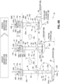
- FIG. 6A is an illustration of a side view of the energy absorbing landing gear system 10, such as in the form of energy absorbing landing gear system 10a, of the disclosure, in an unassembled arrangement 223, with the load limiter assembly 14, such as in the form of the load limiter assembly 14a, separated from the linear damper assembly 12.
- the linear damper assembly 12 is designated as energy absorption structure A 224, and is configured to function, and functions, as a hydraulic shock absorber 70c
- the load limiter assembly 14 is designated as energy absorption structure B 226, and is configured to function, and functions, as a mechanical shock absorber 206.
- the load limiter assembly 14 is configured for coupling, and couples, to the linear damper assembly 12, and the load limiter assembly 14 is configured to integrate, and integrates, into the attachment member 52 comprising the structural attachment fitting 54, such as in the form of the first structural attachment fitting 54a, which is attached around the second end 94b (see FIGS. 2B , 4A ) of the cylinder 92.
- the energy absorbing landing gear system 10 comprises the linear damper assembly 12 with the linear damper 70 coupled, or attached, to the base member 72, such as in the form of landing pad 72a, where the linear damper 70 comprises the piston assembly 74, the cylinder assembly 76, and the cap element 78.
- FIG. 6A shows the piston rod 82 of the piston assembly 74, the cylinder 92 of the cylinder assembly 76, and the first end 110a, the second end 110b, the body 112, the curved portion 114, and the through opening 116, of the cap element 78.
- FIG. 6A shows the piston rod 82 of the piston assembly 74, the cylinder 92 of the cylinder assembly 76, and the first end 110a, the second end 110b, the body 112, the curved portion 114, and the through opening 116, of the cap element 78.
- 6A further shows the attachment member 52 comprising the structural attachment fitting 54, such as in the form of the second structural attachment fitting 54b, which is attached around a portion of the cylinder 92 near the first end 94a (see FIG. 2B ) of the cylinder 92.
- FIG. 6B is an illustration of the energy absorbing landing gear system 10, such as in the form of energy absorbing landing gear system 10a, of FIG. 6A , in an assembled arrangement 229, with the load limiter assembly 14, such as the load limiter assembly 14a, attached to the linear damper assembly 12, and showing the energy absorbing landing gear system 10 in various exemplary positions during the landing phase 32.
- FIG. 6B further shows an energy absorption within A stage 230 of the energy absorption structure A 224 and an energy absorption within B stage 232 of the energy absorption structure B 226.
- the piston assembly 74 of the energy absorbing landing gear system 10 upon landing during the landing phase 32, the piston assembly 74 of the energy absorbing landing gear system 10, such as in the form of energy absorbing landing gear system 10a, is fully extended, with the piston rod 82 fully extending downwardly from the cylinder 92 of the cylinder assembly 76, and an impact force 235 is applied upward, and an opposing normal force 236 is applied downward, to cause the piston assembly 74, including the piston rod 82 and the piston 88, to translate, or move, upwardly in a translation direction 238 into the cylinder 92 of the cylinder assembly 76.
- the linear damper assembly 12 comprising the energy absorption structure A 224 (see FIG. 6B ) absorbs kinetic energy 42 (see FIG. 1 ) during the landing phase 32, such as from a vertical landing motion 34 (see FIG. 1 ) of the vertical landing apparatus 20 (see FIGS. 1 , 8 ) with the attached one or more energy absorbing landing gear systems 10.
- FIG. 6B further shows, in the first position 234a, the piston rod 82 attached to the base member 72, such as the landing pad 72a, and the bottom end 120a of the base member 72 in contact with the landing surface 36, such as the ground 36a, and shows the load limiter assembly, such as the first load limiter assembly 14a, with the deformable element 130 and the pin 168 coupled to the deformable element 130 and the cap element 78.
- the load limiter assembly such as the first load limiter assembly 14a
- the piston assembly 74 in a progression 240 from the first position 234a to a second position 234b, the piston assembly 74, including the piston rod 82 and the piston 88, translates, or moves, and compresses the first compression distance 107 into the cylinder 92 of the cylinder assembly 76.
- the piston assembly 74, including the piston rod 82 and the piston 88, of the linear damper assembly 12 in the second position 234b during the landing phase 32, the piston assembly 74, including the piston rod 82 and the piston 88, of the linear damper assembly 12 is fully translated and compressed into the cylinder 92 of the cylinder assembly 76, until the piston assembly 74, including the piston 88, contacts an internal stop element 241 (see FIG.
- FIG. 6B further shows the impact force 235, the opposing normal force 236, and a piston stroke 242 in the second position 234b.
- the piston stroke 242 corresponds to the first compression distance 107 that the piston assembly 74, including the piston rod 82 and the piston 88 (see FIG.
- 6B further shows, in the second position 234b, the piston rod 82 attached to the base member 72, such as the landing pad 72a, and the bottom end 120a of the base member 72 in contact with the landing surface 36, such as the ground 36a, and shows the load limiter assembly, such as the load limiter assembly 14a, with the deformable element 130 in the undeformed position 186a, and the pin 168 coupled to the cap element 78 and the pin 168 in the start position 188a.
- the load limiter assembly such as the load limiter assembly 14a
- the linear damper assembly 12 causes the linear damper assembly 12, including the piston assembly 74 and the cylinder assembly 76, to translate, or move, and compress upwardly into the load limiter assembly 14, such as the first load limiter assembly 14a, in a translation direction 246, and the deformable element 130 absorbs the excess kinetic energy 42a and deforms to obtain the deformed element 131.
- the deformable element 130 absorbs the excess kinetic energy 42a and irreversibly deforms.
- the exterior 96a of the cylinder 92 slides and translates over the sliding bearings 64 (see FIGS. 4A , 5A-5C ), such as the low friction sliding bearings, positioned between the exterior 96a of the cylinder 92 and interior portions 68 (see FIG. 5C ) of each of the attachment members 52 (see FIG. 6A ), such as the structural attachment fittings 54 (see FIG. 6A ).
- the pin 168 is in the end position 188b and is coupled to the cap element 78.
- the pin 168 has moved or torn through the deformable element 130 of the second position 234b, to form or obtain the deformed element 131 in the deformed position 186b shown in the third position 234c.
- the load limiter assembly 14 comprising the energy absorption structure B 226 (see FIG. 6B ) thus absorbs the excess kinetic energy 42a (see FIG. 1 ) from the translation of both the piston assembly 74 and the cylinder assembly 76 of the linear damper assembly 12, into the load limiter assembly 14, to deform, or irreversibly deform, the deformable element 130 to result in and obtain the deformed element 131.
- the load limiter assembly 14 provides a linear force as it deforms and then reaches a limit at which it yields at a constant force.
- the third position 234c of FIG. 6B further shows the impact force 235, the opposing normal force 236, and a piston and cylinder stroke 198, which corresponds to the second compression distance 189 that the piston assembly 74 and the cylinder assembly 76 of the linear damper assembly 12, translate, or move, and compress upwardly into the load limiter assembly 14, such as the load limiter assembly 14a.
- the third position 234c of FIG. 6B further shows the piston rod 82 attached to the base member 72, such as the landing pad 72a, in contact with the landing surface 36, such as the ground 36a.
- FIG. 7 is a front perspective view of a version of the energy absorbing landing gear system 10, such as in the form of energy absorbing landing gear system 10a, of the disclosure, where the energy absorbing landing gear system 10 is attached to, and installed in, a vertical landing apparatus 20, such as an aircraft 20a.
- the energy absorbing landing gear system 10 is attached to the structural frame 24, such as the airframe 24a, of the vertical landing apparatus 20, via attachment members 52 comprising structural attachment fittings 54, such as in the form of first structural attachment fitting 54a and second structural attachment fitting 54b, each having the planar surface portion 56 with four sides 62 depending from the planar surface portion 56.
- Each attachment member 52 may be attached to the structural frame 24 of the vertical landing apparatus 20 with a means of attachment, such as by fastening with one or more fastening elements, for example, bolts, rivets, screws, or other suitable fastening elements, or by welding, or by adhesive bonding, or by another suitable means of attachment.
- a means of attachment such as by fastening with one or more fastening elements, for example, bolts, rivets, screws, or other suitable fastening elements, or by welding, or by adhesive bonding, or by another suitable means of attachment.
- FIG. 7 shows an exemplary version of how the energy absorbing landing gear system 10 is attached to the vertical landing apparatus 20 with the structural attachment fittings 54.
- the energy absorbing landing gear system 10 may be attached to the vertical landing apparatus 20 with other means of attachment other than the attachment members 52, such as the structural attachment fittings 54.
- the energy absorbing landing gear system 10 may be attached to the vertical landing apparatus 20 directly with one or more fastening elements, by welding, by adhesive bonding, or by another suitable means of attachment, or the energy absorbing landing gear system 10 may be attached to the vertical landing apparatus 20 via another type of structural attachment apparatus or device.
- the energy absorbing landing gear system 10 comprises the linear damper assembly 12 attached to the load limiter assembly 14, such as in the form of the load limiter assembly 14a, as discussed above with regard to FIG. 4A .
- the linear damper assembly 12 comprises the piston assembly 74 with the piston rod 82 attached between the base member 72, such as in the form of landing pad 72a, and the cylinder assembly 76 having the cylinder 92.
- the cap element 78 is coupled atop the cylinder 92 and is coupled to the tubular fitting 132, such as the open tubular fitting 132a, via the pin 168, which pin 168 is inserted through the deformable elements 130 and through the cap element 78.
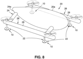
- FIG. 8 is a front perspective view of an exemplary version of a vertical landing apparatus 20, such as an aircraft 20a, having four energy absorbing landing gear systems 10, as disclosed herein, attached to the vertical landing apparatus 20.
- a vertical landing apparatus 20 comprising one or more energy absorbing landing gear systems 10.
- the vertical landing apparatus 20 comprises the structural frame 24 (see FIGS. 1 , 8 ), such as the airframe 24a (see FIGS. 1 , 8 ).
- the structural frame 24, such as the airframe 24a includes attachment portions 26, such as in the form of booms 28.
- each of the energy absorbing landing gear systems 10 is attached to the attachment portions 26, such as the booms 28, where two energy absorbing landing gear systems 10 are attached to one boom 28 and two energy absorbing landing gear systems 10 are attached to another boom 28.
- the four energy absorbing landing gear systems 10 are attached to the vertical landing apparatus 20 so that they are in vertical alignment 22 (see FIG. 8 ) with each other.
- FIG. 8 shows an exemplary version of the vertical landing apparatus 20 and how multiple energy absorbing landing gear systems 10 are attached to the vertical landing apparatus 20.
- the vertical landing apparatus 20 may comprise one of, the aircraft 20a (see FIGS. 1 , 8 ), a vertical take-off and landing (VTOL) aircraft 20b (see FIG. 1 ), a manned aircraft 20c (see FIG. 1 ), an unmanned aerial vehicle (UAV) 20d (see FIG. 1 ), a rotorcraft 20e (see FIG. 1 ), an airdrop container 20f (see FIG. 1 ) configured to land in the vertical landing motion 34 (see FIG. 1 ), or another suitable vertical landing apparatus.
- the aircraft 20a see FIGS. 1 , 8
- VTOL vertical take-off and landing
- UAV unmanned aerial vehicle
- UAV unmanned aerial vehicle
- rotorcraft 20e see FIG. 1
- an airdrop container 20f shown to land in the vertical landing motion 34 (see FIG. 1 ), or another suitable vertical landing apparatus.
- each of the one or more energy absorbing landing gear systems 10 is attached to the structural frame 24, via one or more attachment members 52 (see FIGS. 1 , 2A , 3A ), such as one or more structural attachment fittings 54 (see FIGS. 2A , 3A ), and one or more sliding bearings 64 (see FIGS. 1 , 4A , 5A ) are preferably disposed between each of the one or more structural attachment fittings 54 and the cylinder 92 of the linear damper assembly 12 of each of the one or more energy absorbing landing gear systems 10.
- each of the one or more energy absorbing landing gear systems 10 comprises the load limiter assembly 14 (see FIG. 1 ) coupled to the linear damper assembly 12 (see FIG. 1 ).
- the load limiter assembly 14 is coupled in a series configuration 16 (see FIG. 1 ) to, and atop, the linear damper assembly 12.
- the linear damper assembly 12 comprises the linear damper 70 (see FIGS. 1 , 2A , 3A ) coupled to the base member 72 (see FIGS. 1 , 2A , 3A ), and the linear damper 70 comprises one of, an oil-gas damper 70a (see FIG. 1 ), a gas spring 70b (see FIG. 1 ), a hydraulic shock absorber 70c (see FIG. 1 ), an elastic damper 70d (see FIG. 1 ), or another suitable linear damper.
- the linear damper assembly 12 absorbs kinetic energy 42 (see FIG.
- the load limiter assembly 14 has at least one deformable element 130 (see FIGS. 1 , 2A , 4A , 5A ) to enhance the energy absorption capability 48 (see FIG. 1 ).
- the load limiter assembly 14 comprises the tubular fitting 132, such as the open tubular fitting 132a, incorporating two deformable elements 130a, 130b aligned opposite each other on the tubular fitting 132. In an example, as discussed above with regard to FIGS.
- the load limiter assembly 14 comprises the tubular fitting 132, such as the closed tubular fitting 132b, and the at least one deformable element 130 disposed in the interior 144a of the closed tubular fitting 132b and mounted atop the linear damper assembly 12 comprises the deformable crush element 210, such as the metal honeycomb crush element 210a (see FIG. 1 ), for example, the aluminum honeycomb crush element 210b.
- FIG. 9 is an illustration of a flow diagram showing an exemplary version of a method 250 of the disclosure.
- the method 250 (see FIG. 9 ) of using one or more energy absorbing landing gear systems 10 (see FIG. 1 ) attached to a vertical landing apparatus 20 (see FIG. 1 ) during a landing phase 32 (see FIG. 1 ) of the vertical landing apparatus 20.
- FIG. 9 represent operations and/or portions thereof, and lines connecting the various blocks do not imply any particular order or dependency of the operations or portions thereof.
- FIG. 9 and the disclosure of the steps of the method 250, set forth herein, should not be interpreted as necessarily determining a sequence in which the steps are to be performed. Rather, although one illustrative order is indicated, it is to be understood that the sequence of the steps may be modified when appropriate. Accordingly, certain operations may be performed in a different order or simultaneously.
- the method 250 comprises the step 252 of operating the vertical landing apparatus 20 to land in a vertical landing motion 34 (see FIG. 1 ) during the landing phase 32 of the vertical landing apparatus 20.
- the vertical landing apparatus 20 has the one or more energy absorbing landing gear systems 10 attached to the structural frame 24 (see FIGS. 1 , 8 ), such as the airframe 24a (see FIGS. 1 , 8 ), of the vertical landing apparatus 20.
- the vertical landing apparatus 20 has four energy absorbing landing gear systems 10 attached to the structural frame 24 in a vertical alignment 22 with each other.
- the vertical landing apparatus 20 may have one, two, three, or more than four energy absorbing landing gear systems 10 attached to the vertical landing apparatus 20.
- the step 252 of operating the vertical landing apparatus 20 further comprises, operating the vertical landing apparatus 20 comprising one of, an aircraft 20a (see FIG. 1 ), a vertical take-off and landing (VTOL) aircraft 20b (see FIG. 1 ), a manned aircraft 20c (see FIG. 1 ), an unmanned aerial vehicle (UAV) 20d (see FIG. 1 ), a rotorcraft 20e (see FIG. 1 ), or an airdrop container 20f (see FIG. 1 ) configured to land in the vertical landing motion 34 (see FIG. 1 ).
- each of the one or more energy absorbing landing gear systems 10 comprises the linear damper assembly 12 (see FIGS.
- FIGS. 1 , 2A , 3A comprising the linear damper 70 (see FIGS. 1 , 2A , 3A ) having a piston assembly 74 (see FIGS. 2A , 3A ), including a piston rod 82 (see FIGS. 2A , 3A ) and a piston 88 (see FIGS. 2A , 3A ), coupled to the base member 72 (see FIGS. 1 , 2A , 3A ).
- the base member 72 interfaces with a landing surface 36 (see FIG. 6B ), such as ground 36a (see FIG. 6B ).
- Each of the one or more energy absorbing landing gear systems 10, as discussed above, further comprises the load limiter assembly 14 coupled to the linear damper assembly 12.
- the load limiter assembly 14 has at least one deformable element 130 (see FIGS. 1 , 2A , 4A , 5A ). In one version, the load limiter assembly 14 is coupled in a series configuration 16 (see FIG. 1 ) to, and atop, the linear damper assembly 12.
- the step 252 of operating the vertical landing apparatus 20 having one or more energy absorbing landing gear systems 10 further comprises, operating the vertical landing apparatus 20 having one or more energy absorbing landing gear systems 10, each comprising the load limiter assembly 14, such as in the form of the load limiter assembly 14a (see FIG. 4A ), further comprising, a tubular fitting 132 (see FIG. 4A ), such as an open tubular fitting 132a (see FIG. 4A ), incorporating the at least one deformable element 130 (see FIG. 4A ), where the at least one deformable element 130 comprises two deformable elements 130a, 130b (see FIG. 4A ) aligned opposite each other on the tubular fitting 132.
- Each of the two deformable elements 130a, 130b has a through opening 160 (see FIG. 4A ).
- the load limiter assembly 14, such as the first load limiter assembly 14a further comprises the pin 168, such as the shear pin 168a, inserted through each through opening 160 of the two deformable elements 130a, 130b, and the pin 168 being further coupled to the linear damper assembly 12.
- the linear damper assembly 12 translates, or moves, the second compression distance 189 (see FIGS.
- the pin 168 such as the shear pin 168a, tears or moves through the two deformable elements 130a, 130b, to deform the two deformable elements 130a, 130b, and to obtain one or more deformed elements 131 (see FIG. 4C ), such as deformed elements 131a, 131b (see FIG. 4C ).
- the two deformable elements 130a, 130b absorb the excess kinetic energy 42a and irreversibly deform.
- An exemplary step 252 of operating the vertical landing apparatus 20 having one or more energy absorbing landing gear systems 10 further comprises, operating the vertical landing apparatus 20 having one or more energy absorbing landing gear systems 10, each comprising the load limiter assembly 14, such as in the form of the exemplary load limiter assembly 14b (see FIG. 5A ), further comprising, the tubular fitting 132, such as the closed tubular fitting 132b (see FIG. 5A ), and the at least one deformable element 130 is disposed in the interior 144a (see FIG. 5A ) of the closed tubular fitting 132b and mounted atop the linear damper assembly 12.
- the at least one deformable element 130 preferably comprises the deformable crush element 210 (see FIG.
- a metal honeycomb crush element 210a see FIG. 1
- an aluminum honeycomb crush element 210b see FIGS. 1 , 5A
- the linear damper assembly 12 translates, or moves, the second compression distance 189 (see FIG. 5C ) upwardly into the load limiter assembly 14, such as the second load limiter assembly 14b
- the aluminum honeycomb crush element 210b is compressed and deformed.
- the load limiter assembly 14, such as the second load limiter assembly 14b is compressed and irreversibly deformed.
- the method 250 further comprises the step 254 of moving the piston assembly 74 of the linear damper assembly 12 of each of the one or more energy absorbing landing gear systems 10, a first compression distance 107 (see FIGS. 1 , 6B ) toward the load limiter assembly 14, when the base member 72 (see FIG. 6B ) of each of the one or more energy absorbing landing gear systems 10 contacts a landing surface 36 (see FIG. 6B ), such as the ground 36a (see FIG. 6B ), during the landing phase 32 (see FIG. 6B ).
- the linear damper assembly 12 absorbs kinetic energy 42 (see FIG. 1 ) from the vertical landing motion 34 (see FIG. 1 .).
- the method 250 further comprises the step 256 of moving the linear damper assembly 12, including the piston assembly 74 (see FIG. 6B ) and the cylinder assembly 76 (see FIG. 6B ), of each of the one or more energy absorbing landing gear systems 10, a second compression distance 189 (see FIGS. 1 , 4C , 5C , 6B ) upwardly into the load limiter assembly 14 (see FIG. 6B ), when the linear damper assembly 12 (see FIG. 6B ), including the piston assembly 74 (see FIG. 6B ), reaches a maximum compression 146 (see FIGS. 1 , 6B ).
- the method 250 further comprises the step 258 of deforming the at least one deformable element 130 of each of the one or more energy absorbing landing gear systems 10.
- the at least one deformable element 130 of each of the one or more energy absorbing landing gear systems 10 absorbs excess kinetic energy 42a and irreversibly deforms.
- the at least one deformable element 130 of each of the one or more energy absorbing landing gear systems 10 enhances an energy absorption capability 48 during the landing phase 32.
- the step 258 of deforming the at least one deformable element 130 further comprises, obtaining at least one deformed element 131 (see FIGS. 4C , 5C ) that serves as a visual indicator 208 (see FIGS. 1 , 4C , 5C ) that a load threshold 44 (see FIG. 1 ) of the linear damper assembly 12 was exceeded and the vertical landing apparatus 20 experienced a hard-landing load condition 46 (see FIG. 1 ) in a hard landing.
- a known oil-gas damper was compared to the energy absorbing landing gear system of the disclosure with a load limiter assembly having a pin, such as a shear pin, coupled to a deformable element.
- a known oil-gas damper was tested to reach a peak load or a maximum force of 2500 N (two thousand five hundred Newtons) in a hard-landing load condition.
- a stroke of the cylinder was limited to 200 mm (two hundred millimeters) (7.87 inches).
- the absorbed energy was calculated with a linear damper or strut efficiency number of 80% (eighty percent) and resulted in 400 Nm (four hundred Newton meters) of energy absorption capability.
- the pin such as the shear pin
- adding the pin such as the shear pin, triggered at a peak load or a maximum force of 2700 N (two thousand seven hundred Newtons) and allowed for a stroke of 40 mm (forty millimeters) (1.57 inches).
- the absorbed energy was calculated with a linear damper or strut efficiency number of close to 100% (one hundred percent).
- the efficiency of the energy absorbing landing gear system of the disclosure with the load limiter assembly having the pin, such as the shear pin, coupled to the deformable element was higher than the known oil-gas damper at the cost of the deformable element torn by the pin having a deformation, such as an irreversible deformation.
- FIG. 10 is a flow diagram of an embodiment of an aircraft manufacturing and service method 300
- FIG. 11 is an illustration of a functional block diagram of an embodiment of an aircraft 316.
- the exemplary aircraft manufacturing and service method 300 may include specification and design 302 (see FIG. 10 ) of the aircraft 316 (see FIG. 11 ) and material procurement 304 (see FIG. 10 ).
- material procurement 304 see FIG. 10
- component and subassembly manufacturing 306 see FIG.
- the aircraft 316 (see FIG. 11 ) and system integration 308 (see FIG. 10 ) of the aircraft 316 (see FIG. 11 ) takes place. Thereafter, the aircraft 316 (see FIG. 11 ) may go through certification and delivery 310 (see FIG. 10 ) in order to be placed in service 312 (see FIG. 10 ).
- Each of the processes of the aircraft manufacturing and service method 300 may be performed or carried out by a system integrator, a third party, and/or an operator (e.g., a customer).
- a system integrator may include, without limitation, any number of aircraft manufacturers and major-system subcontractors
- a third party may include, without limitation, any number of vendors, subcontractors, and suppliers
- an operator may include an airline, leasing company, military entity, service organization, and other suitable operators.
- the aircraft 316 produced by the exemplary aircraft manufacturing and service method 300 may include an airframe 318 with a plurality of systems 320 and an interior 322.
- examples of the systems 320 may include one or more of a propulsion system 324, an electrical system 326, a hydraulic system 328, and an environmental system 330. Any number of other systems may be included.
- an aerospace example is shown, the principles of the disclosure may be applied to other industries, such as the automotive industry, including automotive vehicles, the marine industry, including watercraft, ships, and submarines, and other suitable industries.
- Methods and systems embodied herein may be employed during any one or more of the stages of the aircraft manufacturing and service method 300 (see FIG. 10 ).
- components or subassemblies corresponding to component and subassembly manufacturing 306 may be fabricated or manufactured in a manner similar to components or subassemblies produced while the aircraft 316 (see FIG. 11 ) is in service 312 (see FIG. 10 ).
- one or more method embodiments, system embodiments, or a combination thereof may be utilized during component and subassembly manufacturing 306 (see FIG. 10 ) and system integration 308 (see FIG. 10 ), for example, by substantially expediting assembly of, or reducing the cost of, the aircraft 316 (see FIG.
- one or more of method versions, system versions, or a combination thereof, may be utilized while the aircraft 316 (see FIG. 11 ) is in service 312 (see FIG. 10 ), for example and without limitation, to maintenance and service 314 (see FIG. 10 ).
- Disclosed versions of the energy absorbing landing gear system 10 combine two energy absorption assemblies or systems, including a load limiter assembly 14 (see FIGS. 1 , 2A , 3A ), coupled to a linear damper assembly 12 (see FIGS. 1 , 2A , 3A ), such as coupled in a series configuration 16 (see FIGS. 1 , 2A , 3A ), to the linear damper assembly 12, to absorb an excess kinetic energy 42a (see FIG. 1 ), and to enhance an energy absorption capability 48 (see FIG. 1 ) and a damping capability for the energy absorbing landing gear system 10 during a vertical landing motion 34 (see FIG.
- the energy absorption capability 48 decreases the risk of possible damage to the structural frame 24 (see FIGS. 1 , 8 ), such as the airframe 24a (see FIGS. 1 , 8 ), of the vertical landing apparatus 20 (see FIGS. 1 , 8 ), during the landing phase 32 of the vertical landing apparatus 20.
- the additional piston and cylinder stroke 198 By measuring the distance of the additional piston and cylinder stroke 198 (see FIGS. 4C , 5C , 6B ), the enhanced energy absorption taken into the load limiter assembly 14 of the energy absorbing landing gear system 10 can be determined.
- the additional piston and cylinder stroke 198 allows more energy to be absorbed.
- disclosed versions of the energy absorbing landing gear system 10 provide the load limiter assembly 14 (see FIGS. 1 , 2A , 3A ) which limits the load to a maximum level.
- the load limiter assembly 14 of the energy absorbing landing gear system 10 (see FIGS. 1 , 2A-2C , 3A-3B ), and the method 250 (see FIG. 9 ) prevent a load peak when the piston assembly 74 (see FIGS. 2A , 3A ), including the piston rod 82 (see FIGS. 2A , 3A ), is fully compressed at a maximum compression 146 (see FIGS.
- the load threshold 44 (see FIG. 1 ) and the trigger load 204 (see FIG. 1 ) may be tuned by selection of the material thickness, material type, and/or material density of the deformable element material 162 (see FIG. 1 ), such as aluminum for machined features 148 (see FIG. 4A ), or aluminum honeycomb material for the aluminum honeycomb crush element 210b (see FIG. 5A ), or other suitable deformable element materials.
- the load threshold 44 (see FIG. 1 ) and the trigger load 204 (see FIG. 1 ) may be further tuned by selection of the diameter 176 (see FIG. 2C ) of the cylindrical shaft 172 (see FIG. 2C ) of the pin 168 (see FIG. 2C ), such as the shear pin 168a (see FIG. 2C ).
- the deformed element 131 (see FIGS. 1 , 4C , 5C ) of disclosed versions of the energy absorbing landing gear system 10 (see FIGS. 1 , 2A-2C , 3A-3B ) serves, or functions, as a visual indicator 208 (see FIGS. 1 , 4C , 5C ) that the load threshold 44 (see FIG. 1 ) of the linear damper assembly 12 (see FIG. 1 ) was exceeded, and that the energy absorbing landing gear system 10 (see FIG. 1 ) is overloaded or has absorbed additional load, which is more than it was designed to handle, such as due to a hard-landing load condition 46 (see FIG. 1 ) during a hard landing of the vertical landing apparatus 20 (see FIG.
- an indicator or a reference line on the cylinder 92 of the linear damper 70 such as the oil-gas damper 70a, may be used to visually indicate or show whether the cylinder 92 has moved or not.
- Such indicator or reference line may comprise a marking, a sticker, or another suitable indicator.
- the load limiter assembly 14 having the at least one deformed element 131 (see FIGS. 4C , 5C ) that is deformed, or irreversibly deformed, may be inspected, and replaced or exchanged with a load limiter assembly 14 having the at least one deformable element 130 (see FIGS. 4B , 5B ) that is not damaged or irreversibly deformed.
- the deformed element 131 acts as a load fuse, and may be checked in each post-flight checklist, and serves as a visual instrumentation.
- the deformed element 131 is inspectable, exchangeable, replaceable, and provides visual information that the linear damper assembly 12 was overloaded.
- the deformed element 131 which serves, or functions, as the visual indicator 208 that deformation 201 (see FIG. 1 ), or irreversible deformation 202 (see FIG. 1 ), has occurred and the trigger load 204 (see FIG. 1 ) has been exceeded, decreases the time and expense of grounding the vertical landing apparatus 20, such as the aircraft 20a, and decreases the time and expense of determining whether or not damage has occurred to the vertical landing apparatus 20.
- the load limiter assembly 14 is typically lighter in weight than the linear damper assembly 12, which is a reversible system.
- a reversible system such as a linear damper assembly 12, e.g., oil-gas damper, to cover design landing loads, and to add a replaceable deformation element, such as the load limiter assembly 14, to cover loads exceeding the design loads.
- the disclosure includes also a not claimed as such energy absorbing landing gear system (ref. 10) for attachment to a vertical landing apparatus (ref. 20), wherein said energy absorbing landing gear system does not fall within the scope of the claims, the energy absorbing landing gear system comprising:
- the load limiter assembly 14 may be coupled in a series configuration 16 to, and atop, the linear damper assembly 12.
- the load limiter assembly 14 may further comprise: a closed tubular fitting 132b; and the at least one deformable element 130 disposed in an interior 144a of the closed tubular fitting 132b and mounted atop the linear damper assembly 12, and the at least one deformable element 130 comprising a deformable crush element 210, wherein when the linear damper assembly 12 moves into the load limiter assembly 14, the deformable crush element 210 is compressed and deformed.
- the deformable crush element 210 may comprise an aluminum honeycomb crush element 210b.
- the at least one deformable element 130 may deform to form at least one deformed element 131, and the at least one deformed element 131 serves as a visual indicator 208 that a load threshold 44 of the linear damper assembly 12 was exceeded.
- the disclosure also includes a not claimed as such vertical landing apparatus (ref. 20) comprising:
- the vertical landing apparatus may comprise one of, an aircraft 20a, a vertical take-off and landing (VTOL) aircraft 20b, a manned aircraft 20c, an unmanned aerial vehicle (UAV) 20d, a rotorcraft 20e, or an airdrop container 20f configured to land in a vertical landing motion 34.
- the one or more energy absorbing landing gear systems (ref. 10) of the vertical landing apparatus mays comprise four energy absorbing landing gear systems attached to the structural frame 24, the four energy absorbing landing gear systems being in a vertical alignment 22 with each other.
- the load limiter assembly 14 of the vertical landing apparatus may further comprise:
- the the load limiter assembly 14 of the vertical landing apparatus may further comprise:
- the disclosure includes a (not claimed as such) method of using one or more energy absorbing landing gear systems (ref. 10) attached to a vertical landing apparatus (ref. 20) during a landing phase 32 of the vertical landing apparatus, the method comprising the steps of:
- operating 252 the vertical landing apparatus may further comprise, operating 252 the vertical landing apparatus comprising one of, an aircraft 20a, a vertical take-off and landing (VTOL) aircraft 20b, a manned aircraft 20c, an unmanned aerial vehicle (UAV) 20d, a rotorcraft 20e, or an airdrop container 20f configured to land in the vertical landing motion 34.
- VTOL vertical take-off and landing
- UAV unmanned aerial vehicle
- Operating 252 the vertical landing apparatus (ref. 20) having one or more energy absorbing landing gear systems (ref. 10) may further comprise, operating 252 the vertical landing apparatus having one or more energy absorbing landing gear systems, each comprising the load limiter assembly 14 further comprising:
- Deforming 258 the at least one deformable element 130 may further comprise, obtaining at least one deformed element 131 that serves as a visual indicator 208 that a load threshold 44 of the linear damper assembly 12 was exceeded and the vertical landing apparatus experienced a hard-landing load condition 46.
- Deforming 258 the at least one deformable element 130 may further comprise, irreversibly deforming the at least one deformable element 130.
Landscapes
- Engineering & Computer Science (AREA)
- Mechanical Engineering (AREA)
- Aviation & Aerospace Engineering (AREA)
- General Engineering & Computer Science (AREA)
- Vibration Dampers (AREA)
Claims (14)
- Energieabsorbierendes Fahrwerksystem (10) zum Anbringen an einer Vertikallandevorrichtung (20), wobei das energieabsorbierende Fahrwerksystem (10) aufweist:eine Lineardämpferanordnung (12); undeine Lastbegrenzeranordnung (14), die mit der Lineardämpferanordnung (12) gekoppelt ist, wobei die Lastbegrenzeranordnung (14) aufweist:- ein rohrförmiges Fitting (132), das mindestens ein verformbares Element (130) eingebaut hat, um ein Energieabsorptionsvermögen (48) zu verbessern, wobei das mindestens ein verformbare Element (130) zwei verformbare Elemente (130a, 130b) aufweist, die an dem rohrförmigen Fitting (132) einander gegenüberliegend ausgerichtet sind, wobei jedes der zwei verformbaren Elemente (130a, 130b) eine Durchgangsöffnung (160) hat; und- einen Stift (168), der durch jede Durchgangsöffnung (160) der zwei verformbaren Elemente (130a, 130b) eingesetzt ist, und der Stift (168) außerdem mit der Lineardämpferanordnung (12) gekoppelt ist,wobei, wenn das energieabsorbierende Fahrwerksystem (10) konfiguriert ist, an der Vertikallandevorrichtung (20) angebracht zu werden, die Lineardämpferanordnung (12) während einer Landephase (32) eine Landefläche (36) kontaktiert und eine Kolbenanordnung (74) der Lineardämpferanordnung (12) sich eine erste Kompressionsstrecke (107) hin zu der Lastbegrenzeranordnung (14) bewegt, undwenn die Lineardämpferanordnung (12) eine maximale Kompression (146) erreicht hat, die Lineardämpferanordnung (12) sich eine zweite Kompressionsstrecke (189) in die Lastbegrenzeranordnung (14) hinein bewegt und das mindestens ein verformbare Element (130) sich verformt, undwenn sich die Lineardämpferanordnung (12) in die Lastbegrenzeranordnung (14) hinein bewegt, der Stift (168) durch die zwei verformbaren Elemente (130a, 130b) reißt, um die zwei verformbaren Elemente (130a, 130b) zu verformen.
- Energieabsorbierendes Fahrwerksystem (10) nach Anspruch 1, wobei die Lineardämpferanordnung (12) aufweist:einen linearen Dämpfer (70), der einen Öl-Gas-Dämpfer (70a) oder eine Gasfeder (70b) oder einen hydraulischen Stoßdämpfer (70c) oder einen elastischen Dämpfer (70d) aufweist, undein Basiselement (72), das mit dem linearen Dämpfer (70) gekoppelt ist, wobei während der Landephase (32) der Vertikallandevorrichtung (20) das Basiselement (72) mit der Landefläche (36) in Berührung kommt.
- Energieabsorbierendes Fahrwerksystem (10) nach Anspruch 1 oder 2, wobei die Lastbegrenzeranordnung (14) in einer gestapelten Reihenkonfiguration (16) mit der Lineardämpferanordnung (12) gekoppelt ist.
- Energieabsorbierendes Fahrwerksystem (10) nach Anspruch 1, 2 oder 3, wobei das mindestens ein verformbare Element (130) sich irreversibel verformt.
- Energieabsorbierendes Fahrwerksystem (10) nach einem der Ansprüche 1 bis 4, wobei die zwei verformbaren Elemente (130a, 130b) maschinell gearbeitete vertikale Rechtecke mit einer gleichen Form und Größe aufweisen.
- Energieabsorbierendes Fahrwerksystem (10) nach einem der Ansprüche 1 bis 5, wobei der Stift (168) aus einem Stiftmaterial (180) hergestellt ist und die zwei verformbaren Elemente (130a, 130b) aus einem verformbaren Elementmaterial (162) hergestellt sind, und das Stiftmaterial (180) eine Festigkeit (182) und ein Belastungsvermögen (184) hat, die größer als eine Festigkeit (164) und ein Belastungsvermögen (166) des verformbaren Elementmaterials (162) sind.
- Energieabsorbierendes Fahrwerksystem (10) nach einem der Ansprüche 1 bis 6, wobei das rohrförmige Fitting (132) eine offene Oberseite (134) und ein Inneres (144), das offen ist, hat, und das rohrförmige Fitting (132) konfiguriert ist, ein Kappenelement (78) der Lineardämpferanordnung (12) zu empfangen und aufzunehmen.
- Energieabsorbierendes Fahrwerksystem (10) nach einem der Ansprüche 1 bis 7, wobei jedes der zwei verformbaren Elemente (130a, 130b) eine Dicke (154) hat, die geringer als eine Dicke (156) eines restlichen Abschnitts (158) des rohrförmigen Fittings (132) ist, der die zwei verformbaren Elemente (130a, 130b) nicht eingebaut hat.
- Vertikallandevorrichtung (20) aufweisend:einen strukturellen Rahmen (24); undein oder mehrere energieabsorbierende Fahrwerksysteme (10) nach einem der Ansprüche 1 bis 8, die jeweils über ein oder mehrere Befestigungselemente (52) an dem strukturellen Rahmen (24) angebracht sind.
- Vertikallandevorrichtung (20) nach Anspruch 9, wobei die Vertikallandevorrichtung (20) ein Luftfahrzeug (20a) oder ein vertikal startendes und landendes (VTOL) Luftfahrzeug (20b) oder ein bemanntes Luftfahrzeug (20c) oder ein unbemanntes Fluggerät (UAV) (20d) oder ein Rotorflugzeug (20e) oder einen Luftabwurfbehälter (20f) aufweist, die jeweils konfiguriert sind, in einer vertikalen Landebewegung (34) zu landen.
- Vertikallandevorrichtung (20) nach Anspruch 9 oder 10, wobei das eine oder die mehreren energieabsorbierenden Fahrwerksysteme (10) vier energieabsorbierende Fahrwerksysteme (10) aufweisen, die an dem strukturellen Rahmen (24) angebracht sind, wobei die vier energieabsorbierenden Fahrwerksysteme (10) in einer zueinander vertikalen Ausrichtung (22) sind.
- Verfahren (250) zur Verwendung eines oder mehrerer energieabsorbierender Fahrwerksysteme (10), die an einer Vertikallandevorrichtung (20) angebracht sind, während einer Landephase (32) der Vertikallandevorrichtung (20), wobei das Verfahren (250) die Schritte aufweist:(252) Betreiben der Vertikallandevorrichtung (20), um in einer vertikalen Landebewegung (34) zu landen, während der Landephase (32), wobei die Vertikallandevorrichtung (20) das ein oder die mehreren energieabsorbierenden Fahrwerksysteme (10) hat, die an einem strukturellen Rahmen (24) der Vertikallandevorrichtung (20) angebracht sind, wobei jedes des einen oder der mehreren energieabsorbierenden Fahrwerksysteme (10) aufweist:eine Lineardämpferanordnung (12), die einen linearen Dämpfer (70) mit einer Kolbenanordnung (74) aufweist, der mit einem Basiselement (72) gekoppelt ist; undeine Lastbegrenzeranordnung (14), die mit der Lineardämpferanordnung (12) gekoppelt ist, wobei die Lastbegrenzeranordnung (14) ein rohrförmiges Fitting (132) mit mindestens einem eingebauten verformbaren Element (130) aufweist, wobei das mindestens ein verformbare Element (130) zwei verformbare Elemente (130a, 130b) aufweist, die an dem rohrförmigen Fitting (132) einander gegenüberliegend ausgerichtet sind, wobei jedes der zwei verformbaren Elemente (130a, 130b) eine Durchgangsöffnung (160) hat; und die Lastbegrenzeranordnung ferner einen Stift (168) aufweist, der durch jede Durchgangsöffnung (160) der zwei verformbaren Elemente (130a, 130b) eingesetzt ist, und der Stift (168) außerdem mit der Lineardämpferanordnung (12) gekoppelt ist;(254) Bewegen der Kolbenanordnung (74) der Lineardämpferanordnung (12) jedes des einen oder der mehreren energieabsorbierenden Fahrwerksysteme (10) eine erste Kompressionsstrecke (107) hin zu der Lastbegrenzeranordnung (14), wenn das Basiselement (72) jedes des einen oder der mehreren energieabsorbierenden Fahrwerksysteme (10) während der Landephase (32) eine Landefläche (36) kontaktiert;(256) Bewegen der Lineardämpferanordnung (12) jedes des einen oder der mehreren energieabsorbierenden Fahrwerksysteme (10) eine zweite Kompressionsstrecke (189) in die Lastbegrenzeranordnung (14) hinein, wenn die Lineardämpferanordnung (12) eine maximale Kompression (146) erreicht hat; und(258) Verformen des mindestens eines verformbaren Elements (130) jedes des einen oder der mehreren energieabsorbierenden Fahrwerksysteme (10), wobei, wenn die Lineardämpferanordnung (12) sich in die Lastbegrenzeranordnung (14) hinein bewegt, der Stift (168) durch die zwei verformbaren Elemente (130a, 130b) reißt, um die zwei verformbaren Elemente (130a, 130b) zu verformen.
- Verfahren nach Anspruch 12, wobei Betreiben der Vertikallandevorrichtung ferner aufweist: Betreiben eines Luftfahrzeugs (20a) oder eines vertikal startenden und landenden (VTOL) Luftfahrzeugs (20b) oder eines bemannten Luftfahrzeugs (20c) oder eines unbemannten Fluggeräts (UAV) (20b) oder eines Rotorflugzeugs (20e) oder eines Luftabwurfbehälters (20f), die jeweils konfiguriert sind, in einer vertikalen Landebewegung (34) zu landen.
- Verfahren nach Anspruch 12, wobei Verformen (258) des mindestens einen verformbaren Elements (130) ferner aufweist: Erzielen mindestens eines verformten Elements (131), das als ein visueller Indikator (208) dafür dient, dass eine Belastungsschwelle (44) der Lineardämpferanordnung (12) überschritten wurde und die Vertikallandevorrichtung eine Belastungsbedingung (46) einer harten Landung durchgemacht hat.
Applications Claiming Priority (1)
| Application Number | Priority Date | Filing Date | Title |
|---|---|---|---|
| US16/826,246 US11332238B2 (en) | 2020-03-22 | 2020-03-22 | Energy absorbing landing gear system for a vertical landing apparatus and method of using the same |
Publications (2)
| Publication Number | Publication Date |
|---|---|
| EP3885256A1 EP3885256A1 (de) | 2021-09-29 |
| EP3885256B1 true EP3885256B1 (de) | 2024-01-03 |
Family
ID=75111552
Family Applications (1)
| Application Number | Title | Priority Date | Filing Date |
|---|---|---|---|
| EP21163934.9A Active EP3885256B1 (de) | 2020-03-22 | 2021-03-22 | Energieabsorbierendes fahrwerkssystem für eine vorrichtung zum vertikalen landen und verfahren zur verwendung davon |
Country Status (5)
| Country | Link |
|---|---|
| US (1) | US11332238B2 (de) |
| EP (1) | EP3885256B1 (de) |
| JP (1) | JP7769473B2 (de) |
| CN (1) | CN113492970A (de) |
| CA (1) | CA3113031C (de) |
Families Citing this family (13)
| Publication number | Priority date | Publication date | Assignee | Title |
|---|---|---|---|---|
| US20210078697A1 (en) * | 2019-09-13 | 2021-03-18 | Shake N Bake Llc | Shock absorbing foot piece for small apparatus |
| FR3107697B1 (fr) * | 2020-03-02 | 2025-03-14 | Zipair | Dispositif de propulsion et procédé de pilotage de l’atterrissage d’un tel dispositif de propulsion associé |
| WO2022132669A1 (en) * | 2020-12-14 | 2022-06-23 | Spaceryde Inc. | System and devices for high altitidue atmospheric payload transportation and deployment |
| CN114394225B (zh) * | 2022-01-29 | 2023-11-28 | 上海峰飞航空科技有限公司 | 一种复合翼无人机垂直尾翼 |
| US12054282B2 (en) * | 2022-05-23 | 2024-08-06 | Safran Landing Systems Canada Inc. | Landing gear load detection system |
| US12084169B2 (en) * | 2022-10-26 | 2024-09-10 | Safran Landing Systems Canada Inc. | Retractable body mounted landing gear with secondary crash attenuation |
| CN115949693B (zh) * | 2022-12-13 | 2024-05-24 | 浙江方泰汽车配件有限公司 | 一种叶轮馈能式减震阻尼杆 |
| CN116007878B (zh) * | 2022-12-20 | 2025-12-30 | 中国直升机设计研究所 | 一种抗坠毁试验剩余能量吸收装置 |
| WO2024226793A2 (en) * | 2023-04-28 | 2024-10-31 | World View Enterprises Inc. | Deployable landing gear systems |
| CN116834948B (zh) * | 2023-06-05 | 2025-07-22 | 中国直升机设计研究所 | 一种抗坠毁支柱式起落架缓冲器 |
| US12325540B1 (en) | 2023-12-06 | 2025-06-10 | Pipistrel D.O.O. | Aircraft with multifunctional structure |
| US12583635B2 (en) | 2024-01-12 | 2026-03-24 | Textron Systems Corporation | Utilizing multi-directional energy-absorbing landing gear for vertical takeoff and landing |
| US20260062120A1 (en) * | 2024-09-03 | 2026-03-05 | Pipistrel D.O.O. | Multi-Purpose Attachment Structure |
Family Cites Families (21)
| Publication number | Priority date | Publication date | Assignee | Title |
|---|---|---|---|---|
| US3997133A (en) * | 1975-07-30 | 1976-12-14 | Textron, Inc. | Crash attenuation landing gear |
| CA1107769A (en) * | 1978-05-10 | 1981-08-25 | Henry E. Wilson | Composite fibrous tube energy absorber |
| US4336868A (en) * | 1978-05-10 | 1982-06-29 | Textron, Inc. | Composite fibrous tube energy absorber |
| FR2608242B1 (fr) | 1986-12-12 | 1989-03-31 | Aerospatiale | Amortisseur-verin, contre-fiche le comportant, et train d'atterrissage equipe d'une telle contre-fiche |
| FR2681308B1 (fr) | 1991-09-17 | 1993-12-17 | Messier Bugatti | Amortisseur anti-crash relevable. |
| FR2689088B1 (fr) * | 1992-03-31 | 1994-05-13 | Messier Bugatti | Amortisseur-verin destine a l'equipement d'atterrisseurs d'aerodynes, notamment d'helicopteres. |
| DE4312343C2 (de) | 1993-04-15 | 1997-01-23 | Eurocopter Deutschland | Überlastabsorber in Faserverbundbauweise |
| US5547148A (en) * | 1994-11-18 | 1996-08-20 | United Technologies Corporation | Crashworthy landing gear |
| US6328259B1 (en) * | 2000-06-06 | 2001-12-11 | The Boeing Company | Variable-load shear collar for helicopter landing gear shock struts |
| FR2892700B1 (fr) * | 2005-10-27 | 2009-04-24 | Messier Dowty Sa Sa | Amortisseur d'atterrisseur a retenue positive en position retractee et surcourse de crash |
| US8616146B2 (en) * | 2010-03-05 | 2013-12-31 | Goodrich Corporation | System for indicating an airplane hard landing |
| ITMI20130604A1 (it) * | 2013-04-12 | 2014-10-13 | Sia Aerospace S R L | Dispositivo assorbitore d'urti, particolarmente per velivoli |
| CN103935525B (zh) | 2014-04-24 | 2016-01-20 | 南京航空航天大学 | 可重复使用运载器的缓冲着陆腿及其缓冲方法 |
| CN104843050B (zh) * | 2014-09-05 | 2017-08-04 | 北汽福田汽车股份有限公司 | 一种转向管柱总成及具有其的车辆 |
| JP6689166B2 (ja) | 2016-09-06 | 2020-04-28 | Jfeシビル株式会社 | ダンパーシステム |
| FR3062112B1 (fr) | 2017-01-26 | 2023-10-20 | Airbus Helicopters | Atterrisseur d'aeronef comportant un systeme ecreteur d'effort a friction |
| CN206900639U (zh) | 2017-03-23 | 2018-01-19 | 四川建筑职业技术学院 | 一种无人机减震起落架 |
| CN106986006B (zh) | 2017-04-11 | 2020-04-24 | 重庆大学 | 可重复使用的变角度变长度自适应缓冲着陆机构 |
| CN207466962U (zh) * | 2017-10-19 | 2018-06-08 | 董华 | 一种旋翼无人机减震起落架 |
| CN109808771B (zh) * | 2017-11-20 | 2020-09-29 | 上海汽车集团股份有限公司 | 一种车辆、副车架安装结构及其设计方法 |
| US11198504B2 (en) * | 2019-04-30 | 2021-12-14 | Textron Innovations Inc. | Energy absorbing landing systems for aircraft |
-
2020
- 2020-03-22 US US16/826,246 patent/US11332238B2/en active Active
-
2021
- 2021-03-22 CN CN202110301627.0A patent/CN113492970A/zh active Pending
- 2021-03-22 EP EP21163934.9A patent/EP3885256B1/de active Active
- 2021-03-22 JP JP2021047100A patent/JP7769473B2/ja active Active
- 2021-03-23 CA CA3113031A patent/CA3113031C/en active Active
Also Published As
| Publication number | Publication date |
|---|---|
| EP3885256A1 (de) | 2021-09-29 |
| US20210291968A1 (en) | 2021-09-23 |
| CA3113031C (en) | 2026-03-17 |
| JP7769473B2 (ja) | 2025-11-13 |
| CA3113031A1 (en) | 2021-09-22 |
| JP2021147045A (ja) | 2021-09-27 |
| US11332238B2 (en) | 2022-05-17 |
| CN113492970A (zh) | 2021-10-12 |
Similar Documents
| Publication | Publication Date | Title |
|---|---|---|
| EP3885256B1 (de) | Energieabsorbierendes fahrwerkssystem für eine vorrichtung zum vertikalen landen und verfahren zur verwendung davon | |
| EP4003835B1 (de) | Stossabsorbierende strebe | |
| US5927646A (en) | Energy absorbing landing gear/tail skid including means for indicating the magnitude of impact loads | |
| CA1235409A (en) | Flexible aircraft girder with high energy absorption | |
| US6776370B2 (en) | Energy-absorbing connecting strut for use as a gearbox suspension strut for rotary wing aircraft | |
| US8342300B2 (en) | Energy adsorber device that adapts automatically to the weight it supports | |
| US3696894A (en) | Acceleration sensitive shock absorber valve | |
| EP2313312B1 (de) | Federbein mit druckentlastung | |
| US3997133A (en) | Crash attenuation landing gear | |
| EP1171343B1 (de) | Kombinierte stossdämpfer und bogiestellantrieb für landefahrwerk | |
| US5996979A (en) | Aircraft shock strut having an improved piston head | |
| CN106628125A (zh) | 一种多旋翼无人机用快拆式吸能起落架 | |
| US8439304B2 (en) | Energy absorber system for an undercarriage, and an aircraft provided with said energy absorber system | |
| US8434718B2 (en) | Reusable rotorcraft bumper, and a rotorcraft having such a bumper | |
| US10822111B2 (en) | System for protecting an aircraft against hard landings | |
| US4637574A (en) | Attenuating, extendible shock-absorbing strut | |
| CN112607007A (zh) | 一种减震起落架及多旋翼无人机 | |
| US11161601B2 (en) | Hydro-elastic damper and an aircraft | |
| Rich | Vulnerability and Crashworthiness in the Design of Rotary Wing Vehicle Structures | |
| Montesarchio | Michele Guida Francesco Marulo Bruno Montesarchio Massimiliano Bruno | |
| Phillips et al. | Crashworthy Landing Gear Study | |
| Och | SS UTRY | |
| Schnitzer | Experimental Evaluation of Low-band-pass Landing-gear Shock Absorber for Pulse Loadings |
Legal Events
| Date | Code | Title | Description |
|---|---|---|---|
| PUAI | Public reference made under article 153(3) epc to a published international application that has entered the european phase |
Free format text: ORIGINAL CODE: 0009012 |
|
| STAA | Information on the status of an ep patent application or granted ep patent |
Free format text: STATUS: THE APPLICATION HAS BEEN PUBLISHED |
|
| AK | Designated contracting states |
Kind code of ref document: A1 Designated state(s): AL AT BE BG CH CY CZ DE DK EE ES FI FR GB GR HR HU IE IS IT LI LT LU LV MC MK MT NL NO PL PT RO RS SE SI SK SM TR |
|
| STAA | Information on the status of an ep patent application or granted ep patent |
Free format text: STATUS: REQUEST FOR EXAMINATION WAS MADE |
|
| 17P | Request for examination filed |
Effective date: 20220328 |
|
| RBV | Designated contracting states (corrected) |
Designated state(s): AL AT BE BG CH CY CZ DE DK EE ES FI FR GB GR HR HU IE IS IT LI LT LU LV MC MK MT NL NO PL PT RO RS SE SI SK SM TR |
|
| RIC1 | Information provided on ipc code assigned before grant |
Ipc: B64C 25/32 19680901ALN20230102BHEP Ipc: F16F 9/19 19680901ALI20230102BHEP Ipc: F16F 9/06 19680901ALI20230102BHEP Ipc: F16F 9/02 19680901ALI20230102BHEP Ipc: B64D 1/14 19680901ALI20230102BHEP Ipc: F16F 7/12 19680901ALI20230102BHEP Ipc: B64C 25/58 19680901AFI20230102BHEP |
|
| GRAP | Despatch of communication of intention to grant a patent |
Free format text: ORIGINAL CODE: EPIDOSNIGR1 |
|
| STAA | Information on the status of an ep patent application or granted ep patent |
Free format text: STATUS: GRANT OF PATENT IS INTENDED |
|
| RIC1 | Information provided on ipc code assigned before grant |
Ipc: B64C 25/32 20060101ALN20230202BHEP Ipc: F16F 9/19 20060101ALI20230202BHEP Ipc: F16F 9/06 20060101ALI20230202BHEP Ipc: F16F 9/02 20060101ALI20230202BHEP Ipc: B64D 1/14 20060101ALI20230202BHEP Ipc: F16F 7/12 20060101ALI20230202BHEP Ipc: B64C 25/58 20060101AFI20230202BHEP |
|
| INTG | Intention to grant announced |
Effective date: 20230224 |
|
| RIC1 | Information provided on ipc code assigned before grant |
Ipc: B64C 25/32 20060101ALN20230213BHEP Ipc: F16F 9/19 20060101ALI20230213BHEP Ipc: F16F 9/06 20060101ALI20230213BHEP Ipc: F16F 9/02 20060101ALI20230213BHEP Ipc: B64D 1/14 20060101ALI20230213BHEP Ipc: F16F 7/12 20060101ALI20230213BHEP Ipc: B64C 25/58 20060101AFI20230213BHEP |
|
| RIN1 | Information on inventor provided before grant (corrected) |
Inventor name: TISCHHAUSER, FREDERICK |
|
| GRAJ | Information related to disapproval of communication of intention to grant by the applicant or resumption of examination proceedings by the epo deleted |
Free format text: ORIGINAL CODE: EPIDOSDIGR1 |
|
| STAA | Information on the status of an ep patent application or granted ep patent |
Free format text: STATUS: REQUEST FOR EXAMINATION WAS MADE |
|
| GRAP | Despatch of communication of intention to grant a patent |
Free format text: ORIGINAL CODE: EPIDOSNIGR1 |
|
| STAA | Information on the status of an ep patent application or granted ep patent |
Free format text: STATUS: GRANT OF PATENT IS INTENDED |
|
| INTC | Intention to grant announced (deleted) | ||
| RIC1 | Information provided on ipc code assigned before grant |
Ipc: B64C 25/32 20060101ALN20230626BHEP Ipc: F16F 9/19 20060101ALI20230626BHEP Ipc: F16F 9/06 20060101ALI20230626BHEP Ipc: F16F 9/02 20060101ALI20230626BHEP Ipc: B64D 1/14 20060101ALI20230626BHEP Ipc: F16F 7/12 20060101ALI20230626BHEP Ipc: B64C 25/58 20060101AFI20230626BHEP |
|
| RIC1 | Information provided on ipc code assigned before grant |
Ipc: B64C 25/32 20060101ALN20230703BHEP Ipc: F16F 9/19 20060101ALI20230703BHEP Ipc: F16F 9/06 20060101ALI20230703BHEP Ipc: F16F 9/02 20060101ALI20230703BHEP Ipc: B64D 1/14 20060101ALI20230703BHEP Ipc: F16F 7/12 20060101ALI20230703BHEP Ipc: B64C 25/58 20060101AFI20230703BHEP |
|
| RIC1 | Information provided on ipc code assigned before grant |
Ipc: B64C 25/32 20060101ALN20230719BHEP Ipc: F16F 9/19 20060101ALI20230719BHEP Ipc: F16F 9/06 20060101ALI20230719BHEP Ipc: F16F 9/02 20060101ALI20230719BHEP Ipc: B64D 1/14 20060101ALI20230719BHEP Ipc: F16F 7/12 20060101ALI20230719BHEP Ipc: B64C 25/58 20060101AFI20230719BHEP |
|
| INTG | Intention to grant announced |
Effective date: 20230731 |
|
| RIN1 | Information on inventor provided before grant (corrected) |
Inventor name: TISCHHAUSER, FREDERICK |
|
| GRAS | Grant fee paid |
Free format text: ORIGINAL CODE: EPIDOSNIGR3 |
|
| GRAA | (expected) grant |
Free format text: ORIGINAL CODE: 0009210 |
|
| STAA | Information on the status of an ep patent application or granted ep patent |
Free format text: STATUS: THE PATENT HAS BEEN GRANTED |
|
| AK | Designated contracting states |
Kind code of ref document: B1 Designated state(s): AL AT BE BG CH CY CZ DE DK EE ES FI FR GB GR HR HU IE IS IT LI LT LU LV MC MK MT NL NO PL PT RO RS SE SI SK SM TR |
|
| P01 | Opt-out of the competence of the unified patent court (upc) registered |
Effective date: 20231128 |
|
| REG | Reference to a national code |
Ref country code: GB Ref legal event code: FG4D |
|
| REG | Reference to a national code |
Ref country code: DE Ref legal event code: R096 Ref document number: 602021008193 Country of ref document: DE |
|
| REG | Reference to a national code |
Ref country code: CH Ref legal event code: EP |
|
| REG | Reference to a national code |
Ref country code: IE Ref legal event code: FG4D |
|
| REG | Reference to a national code |
Ref country code: LT Ref legal event code: MG9D |
|
| PG25 | Lapsed in a contracting state [announced via postgrant information from national office to epo] |
Ref country code: ES Free format text: LAPSE BECAUSE OF FAILURE TO SUBMIT A TRANSLATION OF THE DESCRIPTION OR TO PAY THE FEE WITHIN THE PRESCRIBED TIME-LIMIT Effective date: 20240103 |
|
| PG25 | Lapsed in a contracting state [announced via postgrant information from national office to epo] |
Ref country code: ES Free format text: LAPSE BECAUSE OF FAILURE TO SUBMIT A TRANSLATION OF THE DESCRIPTION OR TO PAY THE FEE WITHIN THE PRESCRIBED TIME-LIMIT Effective date: 20240103 |
|
| REG | Reference to a national code |
Ref country code: NL Ref legal event code: MP Effective date: 20240103 |
|
| REG | Reference to a national code |
Ref country code: AT Ref legal event code: MK05 Ref document number: 1646549 Country of ref document: AT Kind code of ref document: T Effective date: 20240103 |
|
| PG25 | Lapsed in a contracting state [announced via postgrant information from national office to epo] |
Ref country code: NL Free format text: LAPSE BECAUSE OF FAILURE TO SUBMIT A TRANSLATION OF THE DESCRIPTION OR TO PAY THE FEE WITHIN THE PRESCRIBED TIME-LIMIT Effective date: 20240103 |
|
| PG25 | Lapsed in a contracting state [announced via postgrant information from national office to epo] |
Ref country code: NL Free format text: LAPSE BECAUSE OF FAILURE TO SUBMIT A TRANSLATION OF THE DESCRIPTION OR TO PAY THE FEE WITHIN THE PRESCRIBED TIME-LIMIT Effective date: 20240103 |
|
| PG25 | Lapsed in a contracting state [announced via postgrant information from national office to epo] |
Ref country code: IS Free format text: LAPSE BECAUSE OF FAILURE TO SUBMIT A TRANSLATION OF THE DESCRIPTION OR TO PAY THE FEE WITHIN THE PRESCRIBED TIME-LIMIT Effective date: 20240503 |
|
| PG25 | Lapsed in a contracting state [announced via postgrant information from national office to epo] |
Ref country code: LT Free format text: LAPSE BECAUSE OF FAILURE TO SUBMIT A TRANSLATION OF THE DESCRIPTION OR TO PAY THE FEE WITHIN THE PRESCRIBED TIME-LIMIT Effective date: 20240103 |
|
| PG25 | Lapsed in a contracting state [announced via postgrant information from national office to epo] |
Ref country code: GR Free format text: LAPSE BECAUSE OF FAILURE TO SUBMIT A TRANSLATION OF THE DESCRIPTION OR TO PAY THE FEE WITHIN THE PRESCRIBED TIME-LIMIT Effective date: 20240404 |
|
| PG25 | Lapsed in a contracting state [announced via postgrant information from national office to epo] |
Ref country code: HR Free format text: LAPSE BECAUSE OF FAILURE TO SUBMIT A TRANSLATION OF THE DESCRIPTION OR TO PAY THE FEE WITHIN THE PRESCRIBED TIME-LIMIT Effective date: 20240103 Ref country code: RS Free format text: LAPSE BECAUSE OF FAILURE TO SUBMIT A TRANSLATION OF THE DESCRIPTION OR TO PAY THE FEE WITHIN THE PRESCRIBED TIME-LIMIT Effective date: 20240403 |
|
| PG25 | Lapsed in a contracting state [announced via postgrant information from national office to epo] |
Ref country code: CZ Free format text: LAPSE BECAUSE OF FAILURE TO SUBMIT A TRANSLATION OF THE DESCRIPTION OR TO PAY THE FEE WITHIN THE PRESCRIBED TIME-LIMIT Effective date: 20240103 Ref country code: AT Free format text: LAPSE BECAUSE OF FAILURE TO SUBMIT A TRANSLATION OF THE DESCRIPTION OR TO PAY THE FEE WITHIN THE PRESCRIBED TIME-LIMIT Effective date: 20240103 |
|
| PG25 | Lapsed in a contracting state [announced via postgrant information from national office to epo] |
Ref country code: RS Free format text: LAPSE BECAUSE OF FAILURE TO SUBMIT A TRANSLATION OF THE DESCRIPTION OR TO PAY THE FEE WITHIN THE PRESCRIBED TIME-LIMIT Effective date: 20240403 Ref country code: NO Free format text: LAPSE BECAUSE OF FAILURE TO SUBMIT A TRANSLATION OF THE DESCRIPTION OR TO PAY THE FEE WITHIN THE PRESCRIBED TIME-LIMIT Effective date: 20240403 Ref country code: LT Free format text: LAPSE BECAUSE OF FAILURE TO SUBMIT A TRANSLATION OF THE DESCRIPTION OR TO PAY THE FEE WITHIN THE PRESCRIBED TIME-LIMIT Effective date: 20240103 Ref country code: IS Free format text: LAPSE BECAUSE OF FAILURE TO SUBMIT A TRANSLATION OF THE DESCRIPTION OR TO PAY THE FEE WITHIN THE PRESCRIBED TIME-LIMIT Effective date: 20240503 Ref country code: HR Free format text: LAPSE BECAUSE OF FAILURE TO SUBMIT A TRANSLATION OF THE DESCRIPTION OR TO PAY THE FEE WITHIN THE PRESCRIBED TIME-LIMIT Effective date: 20240103 Ref country code: GR Free format text: LAPSE BECAUSE OF FAILURE TO SUBMIT A TRANSLATION OF THE DESCRIPTION OR TO PAY THE FEE WITHIN THE PRESCRIBED TIME-LIMIT Effective date: 20240404 Ref country code: CZ Free format text: LAPSE BECAUSE OF FAILURE TO SUBMIT A TRANSLATION OF THE DESCRIPTION OR TO PAY THE FEE WITHIN THE PRESCRIBED TIME-LIMIT Effective date: 20240103 Ref country code: BG Free format text: LAPSE BECAUSE OF FAILURE TO SUBMIT A TRANSLATION OF THE DESCRIPTION OR TO PAY THE FEE WITHIN THE PRESCRIBED TIME-LIMIT Effective date: 20240103 Ref country code: AT Free format text: LAPSE BECAUSE OF FAILURE TO SUBMIT A TRANSLATION OF THE DESCRIPTION OR TO PAY THE FEE WITHIN THE PRESCRIBED TIME-LIMIT Effective date: 20240103 |
|
| PG25 | Lapsed in a contracting state [announced via postgrant information from national office to epo] |
Ref country code: PT Free format text: LAPSE BECAUSE OF FAILURE TO SUBMIT A TRANSLATION OF THE DESCRIPTION OR TO PAY THE FEE WITHIN THE PRESCRIBED TIME-LIMIT Effective date: 20240503 Ref country code: PL Free format text: LAPSE BECAUSE OF FAILURE TO SUBMIT A TRANSLATION OF THE DESCRIPTION OR TO PAY THE FEE WITHIN THE PRESCRIBED TIME-LIMIT Effective date: 20240103 |
|
| PG25 | Lapsed in a contracting state [announced via postgrant information from national office to epo] |
Ref country code: SE Free format text: LAPSE BECAUSE OF FAILURE TO SUBMIT A TRANSLATION OF THE DESCRIPTION OR TO PAY THE FEE WITHIN THE PRESCRIBED TIME-LIMIT Effective date: 20240103 Ref country code: PT Free format text: LAPSE BECAUSE OF FAILURE TO SUBMIT A TRANSLATION OF THE DESCRIPTION OR TO PAY THE FEE WITHIN THE PRESCRIBED TIME-LIMIT Effective date: 20240503 Ref country code: PL Free format text: LAPSE BECAUSE OF FAILURE TO SUBMIT A TRANSLATION OF THE DESCRIPTION OR TO PAY THE FEE WITHIN THE PRESCRIBED TIME-LIMIT Effective date: 20240103 Ref country code: LV Free format text: LAPSE BECAUSE OF FAILURE TO SUBMIT A TRANSLATION OF THE DESCRIPTION OR TO PAY THE FEE WITHIN THE PRESCRIBED TIME-LIMIT Effective date: 20240103 |
|
| REG | Reference to a national code |
Ref country code: DE Ref legal event code: R097 Ref document number: 602021008193 Country of ref document: DE |
|
| PG25 | Lapsed in a contracting state [announced via postgrant information from national office to epo] |
Ref country code: DK Free format text: LAPSE BECAUSE OF FAILURE TO SUBMIT A TRANSLATION OF THE DESCRIPTION OR TO PAY THE FEE WITHIN THE PRESCRIBED TIME-LIMIT Effective date: 20240103 |
|
| PG25 | Lapsed in a contracting state [announced via postgrant information from national office to epo] |
Ref country code: SM Free format text: LAPSE BECAUSE OF FAILURE TO SUBMIT A TRANSLATION OF THE DESCRIPTION OR TO PAY THE FEE WITHIN THE PRESCRIBED TIME-LIMIT Effective date: 20240103 |
|
| PG25 | Lapsed in a contracting state [announced via postgrant information from national office to epo] |
Ref country code: EE Free format text: LAPSE BECAUSE OF FAILURE TO SUBMIT A TRANSLATION OF THE DESCRIPTION OR TO PAY THE FEE WITHIN THE PRESCRIBED TIME-LIMIT Effective date: 20240103 |
|
| PG25 | Lapsed in a contracting state [announced via postgrant information from national office to epo] |
Ref country code: SK Free format text: LAPSE BECAUSE OF FAILURE TO SUBMIT A TRANSLATION OF THE DESCRIPTION OR TO PAY THE FEE WITHIN THE PRESCRIBED TIME-LIMIT Effective date: 20240103 |
|
| PG25 | Lapsed in a contracting state [announced via postgrant information from national office to epo] |
Ref country code: SM Free format text: LAPSE BECAUSE OF FAILURE TO SUBMIT A TRANSLATION OF THE DESCRIPTION OR TO PAY THE FEE WITHIN THE PRESCRIBED TIME-LIMIT Effective date: 20240103 Ref country code: SK Free format text: LAPSE BECAUSE OF FAILURE TO SUBMIT A TRANSLATION OF THE DESCRIPTION OR TO PAY THE FEE WITHIN THE PRESCRIBED TIME-LIMIT Effective date: 20240103 Ref country code: RO Free format text: LAPSE BECAUSE OF FAILURE TO SUBMIT A TRANSLATION OF THE DESCRIPTION OR TO PAY THE FEE WITHIN THE PRESCRIBED TIME-LIMIT Effective date: 20240103 Ref country code: EE Free format text: LAPSE BECAUSE OF FAILURE TO SUBMIT A TRANSLATION OF THE DESCRIPTION OR TO PAY THE FEE WITHIN THE PRESCRIBED TIME-LIMIT Effective date: 20240103 Ref country code: DK Free format text: LAPSE BECAUSE OF FAILURE TO SUBMIT A TRANSLATION OF THE DESCRIPTION OR TO PAY THE FEE WITHIN THE PRESCRIBED TIME-LIMIT Effective date: 20240103 |
|
| REG | Reference to a national code |
Ref country code: CH Ref legal event code: PL |
|
| PLBE | No opposition filed within time limit |
Free format text: ORIGINAL CODE: 0009261 |
|
| STAA | Information on the status of an ep patent application or granted ep patent |
Free format text: STATUS: NO OPPOSITION FILED WITHIN TIME LIMIT |
|
| PG25 | Lapsed in a contracting state [announced via postgrant information from national office to epo] |
Ref country code: LU Free format text: LAPSE BECAUSE OF NON-PAYMENT OF DUE FEES Effective date: 20240322 |
|
| PG25 | Lapsed in a contracting state [announced via postgrant information from national office to epo] |
Ref country code: MC Free format text: LAPSE BECAUSE OF FAILURE TO SUBMIT A TRANSLATION OF THE DESCRIPTION OR TO PAY THE FEE WITHIN THE PRESCRIBED TIME-LIMIT Effective date: 20240103 |
|
| PG25 | Lapsed in a contracting state [announced via postgrant information from national office to epo] |
Ref country code: MC Free format text: LAPSE BECAUSE OF FAILURE TO SUBMIT A TRANSLATION OF THE DESCRIPTION OR TO PAY THE FEE WITHIN THE PRESCRIBED TIME-LIMIT Effective date: 20240103 Ref country code: LU Free format text: LAPSE BECAUSE OF NON-PAYMENT OF DUE FEES Effective date: 20240322 |
|
| PG25 | Lapsed in a contracting state [announced via postgrant information from national office to epo] |
Ref country code: IT Free format text: LAPSE BECAUSE OF FAILURE TO SUBMIT A TRANSLATION OF THE DESCRIPTION OR TO PAY THE FEE WITHIN THE PRESCRIBED TIME-LIMIT Effective date: 20240103 |
|
| 26N | No opposition filed |
Effective date: 20241007 |
|
| REG | Reference to a national code |
Ref country code: BE Ref legal event code: MM Effective date: 20240331 |
|
| PG25 | Lapsed in a contracting state [announced via postgrant information from national office to epo] |
Ref country code: IT Free format text: LAPSE BECAUSE OF FAILURE TO SUBMIT A TRANSLATION OF THE DESCRIPTION OR TO PAY THE FEE WITHIN THE PRESCRIBED TIME-LIMIT Effective date: 20240103 |
|
| PG25 | Lapsed in a contracting state [announced via postgrant information from national office to epo] |
Ref country code: BE Free format text: LAPSE BECAUSE OF NON-PAYMENT OF DUE FEES Effective date: 20240331 |
|
| PG25 | Lapsed in a contracting state [announced via postgrant information from national office to epo] |
Ref country code: IE Free format text: LAPSE BECAUSE OF NON-PAYMENT OF DUE FEES Effective date: 20240322 |
|
| PG25 | Lapsed in a contracting state [announced via postgrant information from national office to epo] |
Ref country code: IE Free format text: LAPSE BECAUSE OF NON-PAYMENT OF DUE FEES Effective date: 20240322 Ref country code: BE Free format text: LAPSE BECAUSE OF NON-PAYMENT OF DUE FEES Effective date: 20240331 Ref country code: CH Free format text: LAPSE BECAUSE OF NON-PAYMENT OF DUE FEES Effective date: 20240331 |
|
| PG25 | Lapsed in a contracting state [announced via postgrant information from national office to epo] |
Ref country code: SI Free format text: LAPSE BECAUSE OF FAILURE TO SUBMIT A TRANSLATION OF THE DESCRIPTION OR TO PAY THE FEE WITHIN THE PRESCRIBED TIME-LIMIT Effective date: 20240103 |
|
| PG25 | Lapsed in a contracting state [announced via postgrant information from national office to epo] |
Ref country code: CY Free format text: LAPSE BECAUSE OF FAILURE TO SUBMIT A TRANSLATION OF THE DESCRIPTION OR TO PAY THE FEE WITHIN THE PRESCRIBED TIME-LIMIT; INVALID AB INITIO Effective date: 20210322 |
|
| PG25 | Lapsed in a contracting state [announced via postgrant information from national office to epo] |
Ref country code: HU Free format text: LAPSE BECAUSE OF FAILURE TO SUBMIT A TRANSLATION OF THE DESCRIPTION OR TO PAY THE FEE WITHIN THE PRESCRIBED TIME-LIMIT; INVALID AB INITIO Effective date: 20210322 |
|
| PG25 | Lapsed in a contracting state [announced via postgrant information from national office to epo] |
Ref country code: FI Free format text: LAPSE BECAUSE OF FAILURE TO SUBMIT A TRANSLATION OF THE DESCRIPTION OR TO PAY THE FEE WITHIN THE PRESCRIBED TIME-LIMIT Effective date: 20240103 |
|
| PG25 | Lapsed in a contracting state [announced via postgrant information from national office to epo] |
Ref country code: TR Free format text: LAPSE BECAUSE OF FAILURE TO SUBMIT A TRANSLATION OF THE DESCRIPTION OR TO PAY THE FEE WITHIN THE PRESCRIBED TIME-LIMIT Effective date: 20240103 |
|
| PGFP | Annual fee paid to national office [announced via postgrant information from national office to epo] |
Ref country code: GB Payment date: 20260327 Year of fee payment: 6 |
|
| PGFP | Annual fee paid to national office [announced via postgrant information from national office to epo] |
Ref country code: DE Payment date: 20260327 Year of fee payment: 6 |
|
| PGFP | Annual fee paid to national office [announced via postgrant information from national office to epo] |
Ref country code: FR Payment date: 20260325 Year of fee payment: 6 |