EP3885266B1 - Hoch-belastungstolerantes profiltiefen eisschutzlayout - Google Patents
Hoch-belastungstolerantes profiltiefen eisschutzlayout Download PDFInfo
- Publication number
- EP3885266B1 EP3885266B1 EP21164913.2A EP21164913A EP3885266B1 EP 3885266 B1 EP3885266 B1 EP 3885266B1 EP 21164913 A EP21164913 A EP 21164913A EP 3885266 B1 EP3885266 B1 EP 3885266B1
- Authority
- EP
- European Patent Office
- Prior art keywords
- zone
- busbar
- airfoil
- zone element
- chord
- Prior art date
- Legal status (The legal status is an assumption and is not a legal conclusion. Google has not performed a legal analysis and makes no representation as to the accuracy of the status listed.)
- Active
Links
Images


Classifications
-
- B—PERFORMING OPERATIONS; TRANSPORTING
- B64—AIRCRAFT; AVIATION; COSMONAUTICS
- B64D—EQUIPMENT FOR FITTING IN OR TO AIRCRAFT; FLIGHT SUITS; PARACHUTES; ARRANGEMENT OR MOUNTING OF POWER PLANTS OR PROPULSION TRANSMISSIONS IN AIRCRAFT
- B64D15/00—De-icing or preventing icing on exterior surfaces of aircraft
- B64D15/12—De-icing or preventing icing on exterior surfaces of aircraft by electric heating
-
- B—PERFORMING OPERATIONS; TRANSPORTING
- B64—AIRCRAFT; AVIATION; COSMONAUTICS
- B64D—EQUIPMENT FOR FITTING IN OR TO AIRCRAFT; FLIGHT SUITS; PARACHUTES; ARRANGEMENT OR MOUNTING OF POWER PLANTS OR PROPULSION TRANSMISSIONS IN AIRCRAFT
- B64D2221/00—Electric power distribution systems onboard aircraft
Definitions
- the present disclosure relates to systems and methods for heating aircraft components using heating mats and in particular, for heating airfoils of aircraft using heating mats.
- heating mats may be placed on such aircraft components at locations that are susceptible to ice formation (such as leading edges of the components). Some of these locations may be subjected to strain (e.g., outer ends of airfoil). This may be especially true for helicopter blades, which may experience significant strain, especially at outboard ends of the helicopter blades.
- US 2018/346133 A1 discloses a heating element assembly for a blade or wing including one or more heating elements, wherein each heating element is electrically connected to an electrical bus bar. Further examples of heating mats are disclosed in US 2018/115127 A1 , US 2019/084682 A1 and GB 2 291 575 A .
- an airfoil comprising a heater mat for heating the airfoil as defined in claim 1.
- the first zone element and the second zone element are etched in at least one of a crisscross pattern or a basket-weave pattern such that the first zone element and the second zone element each includes a conductive material with openings in order to resemble a spring.
- the first zone element and the first zone busbar are a single monolithic piece of material.
- Any of the foregoing embodiments may further include a second zone busbar located at the leading edge and electrically coupled to the second zone element, and a third zone element configured to heat a third chord-wise segment of the airfoil that is adjacent to the second chord-wise segment of the airfoil.
- the third zone element overlaps the second zone busbar.
- the first chord-wise segment of the airfoil is outboard relative to the second chord-wise segment of the airfoil.
- Also disclosed is a method for forming an airfoil comprising a heater mat for heating the airfoil as defined by claim 8.
- the second zone busbar is located at the leading edge.
- providing the first zone element and the second zone element includes etching the first zone element and the second zone element in at least one of a crisscross pattern or a basket-weave pattern such that the first zone element and the second zone element include a conductive material with openings in order to resemble a spring.
- providing the first zone element and the first zone busbar includes forming the first zone element and the first zone busbar monolithically from a single piece of material.
- any reference to singular includes plural embodiments, and any reference to more than one component or step may include a singular embodiment or step.
- any reference to attached, fixed, connected or the like may include permanent, removable, temporary, partial, full and/or any other possible attachment option.
- any reference to without contact (or similar phrases) may also include reduced contact or minimal contact. Surface shading lines may be used throughout the figures to denote different parts but not necessarily to denote the same or different materials.
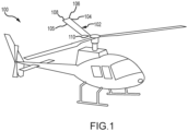
- the aircraft 100 includes a plurality of airfoils 102. Although the aircraft 100 is shown as a helicopter, the features described in the present disclosure are not limited only to helicopters.
- Each of the airfoils 102 includes a leading-edge 104, a trailing edge 105, and outboard end 108, and an inboard end 110.
- the airfoils 102 further includes a heater mat 106.
- the heater mat 106 is located on the airfoils 102 and may provide thermal energy to reduce accumulation of ice.
- the heater mat 106 may experience greater strain at the outboard end 108 than at the inboard end 110.
- the strain may be greatest at a mid-span of the airfoils 102 where flexing is greatest. This strain location may be more prominent in rotorcraft (e.g., helicopters and tilt-rotors).
- the aircraft 100 may be a rotorcraft.
- Conventional heater mats include a plurality of heating elements coupled together via a busbar.
- Conventional heater mats place the busbar on a trailing end of the airfoil.
- the trailing end may experience greater strain, especially towards an outboard end of the airfoil (in various embodiments, the strain may be greatest at a mid-span of the conventional heater mats).
- the busbars of conventional heater mats may experience strain, which may damage the busbars.
- the heater mat 106 includes a first zone element 200, a second zone element 202, a third zone element 204, a fourth zone element 206, a fifth zone element 208, a sixth zone element 210, a seventh zone element 212, and an eighth zone element 214.
- Any of the sixth zone element 210, the seventh zone element 212, or the eighth zone element 214 may be referred to as an inner zone element as they may be located closer to the inboard end 110 than the outboard end 108.
- the second zone element 202 is located adjacent to the first zone element 200 and towards the inboard end 110 relative to the first zone element 200.
- the busbars for each of the first zone element 200, the second zone element 202, the third zone element 204, the fourth zone 206, and the fifth zone element 208 are located at a leading edge of the heater mat 106. This may be because the corresponding zones of the airfoil 102 experience greater strain at the trailing edge 105 (as shown in busbar 1) than at the leading edge 104. By placing the busbars at the leading edge in the outboard five zones, the amount of strain experienced by these busbars is relatively low, thus decreasing the likelihood of a failure due to fatigue.
- the first zone heating element 200 is coupled to a first zone busbar 300
- the second zone element 202 is coupled to a second zone busbar 302
- the third zone element 204 is coupled to a third zone busbar 304
- the fourth zone element 206 is coupled to a fourth zone busbar 306.
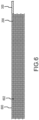
- the first zone element 200 is etched or otherwise formed to be patterned.
- the first zone element 200 may include any pattern such as a crisscross pattern, a basket-weave, or the like.
- the first zone element 200 may include a conductive material 600 with openings 602. This patterning of the first zone element 200 may result in the first zone element 200 having a spring-like nature (i.e., the first zone element 200 may resemble a spring, which may resemble the spring-like nature of a heating element available under the tradename Duratherm ® and available from Goodrich Corporation of Charlotte, NC).
- Each of the zone elements 200, 202, 204, 206, 208, 210, 212, 214 may have similar features as the first zone element 200.
- the spring-like nature of the elements 200, 202, 204, 206, 208, 210, 212, 214 may provide multiple redundant electrical paths for the power to be provided to each of the elements 200, 202, 204, 206, 208, 210, 212, 214.
- the first zone busbar 300 may also include a solid strip of conductive material.
- the spring-like nature of the first zone element 200 results in the first zone element 200 having a greater strain tolerance than the first zone busbar 300.
- the first zone busbar 300 may be formed monolithically with the first zone element 200. That is, a single piece of material may be etched or otherwise reduced or formed to create the first zone element 200 and the first zone busbar 300.
- the first zone busbar 300, the second zone busbar 302, the third zone busbar 304, and the fourth zone busbar 306 are each located at the leading edge 104, as shown by a collection of busbars 400. This reduces strain on the busbars 300, 302, 304, 306 at the leading edge towards the outboard end 108 that experiences less strain than the trailing edge. Thus, this placement of the busbars 300, 302, 304, 306 may increase a lifespan of the heater mat 106.
- first zone element 200, the second zone element 202, the third zone element 204, the fourth zone element 206, and the fifth zone element 208 may be referred to as outer zone elements 200, 202, 204, 206, 208 as they may be located closer to the outboard end 108 than the inboard end 110.
- the first zone busbar 300 is electrically coupled to the first zone element 200
- the second zone busbar 302 is electrically coupled to the second zone element 202
- the third zone busbar 304 may be electrically coupled to the third zone elements 204
- the fourth zone busbar 306 may be electrically coupled to the fourth zone element 206.
- each of the first zone busbar 300, the second zone busbar 302, the third zone busbar 304s, and the fourth zone busbar 306 may include separate power and return paths for each of the first zone element 200, the second zone element 202, the third zone element 204, and the fourth zone element 206 that are routed along the leading edge 104.
- Providing separate power and return paths for each of the outer zone elements reduces the likelihood of failure of the entire heater mat 106 in response to failure of a single busbar. This arrangement further maximizes chordwise coverage of the heater mat 106 because it provides additional surface area of the heater mat 106 where conventional heater mats included power and return paths.
- the fifth zone element 208, the sixth zone element 210, the seventh zone element 212, and the eighth zone element 214 may be electrically coupled to a common busbar 308.
- the common busbar 308 is located at the trailing edge 105 of the heater mat 106.
- the fifth zone element 208, the sixth zone element 210, the seventh zone element 212, and the eighth zone element 214 along with the common busbar 308 may be etched at a single time. Placement of the common busbar 308 for the elements 208, 210, 212, 214 at the trailing edge 105 rather than the leading edge 104 is because strain at the trailing edge 105 is reduced closer to the inboard end 110 relative to the outboard end 108.
- the fifth zone element 208, the sixth zone element 210, the seventh zone element 212, and the eighth zone element 214 are located closer to the inboard and 110 than the outboard end 108, they may be referred to as inner zone elements.
- the inner zone elements 208, 210, 212, 214 may be formed as a single zone element and, in various embodiments, the inner zone elements 208, 210, 212, 214 may be formed as separate elements.
- the common busbar 308 may include a single busbar for the combination of inner zone elements 208, 210, 212, 214 and, in various embodiments, the common busbar 308 may include separate busbars for each of the inner zone elements 208, 210, 212, 214. In various embodiments, the separate busbars may or may not be coupled together.
- the outer zone elements 200, 202, 204, 206, 208 and the inner zone elements 208, 210, 212, 214 may be selected as outer zone elements or inner zone elements based on an amount of strain experienced at various locations along the corridors of the airfoil 102. For example, elements that experience greater strain on a leading edge may be selected as inner zone elements and elements that experience greater strain on a trailing edge may be selected as outer zone elements.
- the outer zone elements 200, 202, 204, 206, 208 and the inner zone elements 208, 210, 212, 214 may be selected as outer zone elements or inner zone elements based on a distance of each of the zone elements 200, 202, 204, 206, 208, 208, 210, 212, 214 from the inboard end 110 and the outboard end 108.
- elements that are closer to the inboard end 110 may be selected as inner zone elements and elements that are closer to the outboard end 108 may be selected as outer zone elements.
- elements that are located in the 60 percent (60%) of the chord length nearest to the outboard end 108 may be selected as outer zone elements and elements that are located in the 40% of the chord length nearest to the inboard end 110 may be selected as inner zone elements.
- first zone element 200 and the first zone busbar 300 are positioned first.
- the second zone element 200 and the second zone busbar 302 are laid such that the second zone element 200 overlays the first zone busbar 300 and the second zone element 202 is located adjacent to the first zone element 200. This may continue until all outer zone elements 200, 202, 204, 206 have been arranged.
- the outer zone elements 200, 202, 204, 206 may account for all areas of relatively high strain on the airfoil 102.
- the inner zone elements 208, 210, 212, 214 may be laid along with the common busbar 308 as a single installation, or the inner zone elements 208, 210, 212, 214 and the common busbar 308 may be installed separately.
- a method 500 for forming a heater mat for use with an airfoil is shown.
- a first zone element and a first zone busbar are provided.
- the first zone element is electrically coupled to the first zone busbar.
- the first zone element and the first zone busbar are placed such that the first zone busbar is located at a leading edge.
- a second zone element and a second zone busbar are provided.
- the second zone busbar is electrically coupled to the second zone element.
- the second zone element and the second zone busbar are placed such that the second zone element is located adjacent to and inboard relative to the first zone element and overlaps the first zone busbar.
- the placement of the second zone element and the second zone busbar may be such that the second zone busbar is also located at the leading edge in block 510.
- Blocks 502 through 510 may be repeated until all outer zone elements have been arranged.
- an inner zone element and an inner zone busbar are provided.
- the inner zone busbar is electrically coupled to the inner zone element.
- the inner zone element and the inner zone busbar are placed such that the inner zone busbar is located on a trailing edge.
- Blocks 512 and 514 may be repeated until all inner zone elements have been installed.
- a single inner zone busbar may be provided that provides power to all inner zone heating elements.
- references to "various embodiments”, “one embodiment”, “an embodiment”, “an example embodiment”, etc. indicate that the embodiment described may include a particular feature, structure, or characteristic, but every embodiment may not necessarily include the particular feature, structure, or characteristic. Moreover, such phrases are not necessarily referring to the same embodiment. Further, when a particular feature, structure, or characteristic is described in connection with an embodiment, it is submitted that it is within the knowledge of one skilled in the art to affect such feature, structure, or characteristic in connection with other embodiments whether or not explicitly described. After reading the description, it will be apparent to one skilled in the relevant art(s) how to implement the disclosure in alternative embodiments within the scope of the claims.
Landscapes
- Engineering & Computer Science (AREA)
- Aviation & Aerospace Engineering (AREA)
- Resistance Heating (AREA)
Claims (11)
- Schaufelblatt (102) mit einem Profil, einer Vorderkante und einer Hinterkante, umfassend:
eine Heizmatte (106) zum Beheizen des Schaufelblatts, wobei die Heizmatte umfasst:ein Element (200) einer ersten Zone, das zum Beheizen eines ersten Profiltiefensegments des Schaufelblatts konfiguriert ist;ein Element (202) einer zweiten Zone, das zum Beheizen eines zweiten Profiltiefensegments des Schaufelblatts konfiguriert ist, das zu dem ersten Profiltiefensegment des Schaufelblatts benachbart ist;eine Sammelschiene (300) der ersten Zone, die an der Vorderkante angeordnet und elektrisch an das Element der ersten Zone gekoppelt ist, wobei das Element der zweiten Zone die Sammelschiene der ersten Zone überlagert;eine Sammelschiene (302) der zweiten Zone, die elektrisch an das Element der zweiten Zone gekoppelt ist;ein Innenzonenelement (210, 212, 214), das dazu konfiguriert ist, ein inneres Profiltiefensegment des Schaufelblatts zu beheizen; undeine Innenzonensammelschiene (304, 306), die an der Hinterkante angeordnet und elektrisch an das Innenzonenelement gekoppelt ist. - Schaufelblatt nach Anspruch 1, wobei das Element (200) der ersten Zone und das Element (202) der zweiten Zone in mindestens einem von einem Kreuzmuster oder einem Korbflechtmuster geätzt sind, derart, dass das Element der ersten Zone und das Element der zweiten Zone jeweils ein leitfähiges Material (600) mit Öffnungen (602) beinhalten, um einer Feder zu gleichen.
- Schaufelblatt nach Anspruch 1, wobei das Element der ersten Zone und die Sammelschiene der ersten Zone ein einzelnes monolithisches Materialstück sind.
- Schaufelblatt nach einem der Ansprüche 1 bis 3, wobei die Sammelschiene (302) der zweiten Zone an der Vorderkante angeordnet ist.
- Schaufelblatt nach Anspruch 1, ferner umfassend ein Element (204) einer dritten Zone, das dazu konfiguriert ist, ein drittes Profiltiefensegment des Schaufelblatts zu beheizen, das zu dem zweiten Profiltiefensegment des Schaufelblatts benachbart ist.
- Schaufelblatt nach Anspruch 5, wobei das Element der dritten Zone die Sammelschiene der zweiten Zone überlagert.
- Schaufelblatt nach einem der vorhergehenden Ansprüche, wobei das erste Profiltiefensegment des Schaufelblatts im Verhältnis zu dem zweiten Profiltiefensegment des Schaufelblatts auswärts liegt.
- Verfahren zum Bilden eines Schaufelblatts nach Anspruch 1, wobei das Verfahren umfasst:Bereitstellen des Elements (200) der ersten Zone und der Sammelschiene (300) der ersten Zone, die elektrisch daran gekoppelt wird;Anordnen des Elements der ersten Zone und der Sammelschiene der ersten Zone derart, dass die Sammelschiene der ersten Zone an der Vorderkante angeordnet wird;Bereitstellen des Elements (202) der zweiten Zone und der Sammelschiene (302) der zweiten Zone, die elektrisch daran gekoppelt wird;Anordnen des Elements der zweiten Zone und der Sammelschiene der zweiten Zone derart, dass das Element der zweiten Zone benachbart zu dem Element der ersten Zone und im Verhältnis dazu einwärts angeordnet wird und die Sammelschiene der ersten Zone überlagert;Bereitstellen des Innenzonenelements und der Innenzonensammelschiene, die elektrisch daran gekoppelt wird; undAnordnen des Innenzonenelements und der Innenzonensammelschiene derart, dass die Innenzonensammelschiene an der Hinterkante angeordnet wird.
- Verfahren nach Anspruch 8, wobei die Sammelschiene der zweiten Zone an der Vorderkante angeordnet wird.
- Verfahren nach Anspruch 8 oder 9, wobei das Bereitstellen des Elements der ersten Zone und des Elements der zweiten Zone Ätzen des Elements der ersten Zone und des Elements der zweiten Zone in mindestens einem von einem Kreuzmuster oder einem Korbflechtmuster beinhaltet, derart, dass das Element der ersten Zone und das Element der zweiten Zone jeweils ein leitfähiges Material (600) mit Öffnungen (602) beinhalten, um einer Feder zu gleichen.
- Verfahren nach einem der Ansprüche 8 bis 10, wobei das Bereitstellen des Elements der ersten Zone und der Sammelschiene der ersten Zone monolithisches Bilden des Elements der ersten Zone und der Sammelschiene der ersten Zone aus einem einzelnen Materialstück beinhaltet.
Applications Claiming Priority (1)
| Application Number | Priority Date | Filing Date | Title |
|---|---|---|---|
| US16/829,855 US11427336B2 (en) | 2020-03-25 | 2020-03-25 | High strain tolerant chord-wise ice protection layout |
Publications (2)
| Publication Number | Publication Date |
|---|---|
| EP3885266A1 EP3885266A1 (de) | 2021-09-29 |
| EP3885266B1 true EP3885266B1 (de) | 2023-08-30 |
Family
ID=75223189
Family Applications (1)
| Application Number | Title | Priority Date | Filing Date |
|---|---|---|---|
| EP21164913.2A Active EP3885266B1 (de) | 2020-03-25 | 2021-03-25 | Hoch-belastungstolerantes profiltiefen eisschutzlayout |
Country Status (2)
| Country | Link |
|---|---|
| US (1) | US11427336B2 (de) |
| EP (1) | EP3885266B1 (de) |
Families Citing this family (1)
| Publication number | Priority date | Publication date | Assignee | Title |
|---|---|---|---|---|
| US12365466B1 (en) | 2024-01-23 | 2025-07-22 | General Electric Company | Power switching system of an anti-ice system for use with a main power supply and an auxiliary power supply |
Family Cites Families (11)
| Publication number | Priority date | Publication date | Assignee | Title |
|---|---|---|---|---|
| GB2291575A (en) | 1994-07-21 | 1996-01-24 | Dowty Aerospace Gloucester | Heating element for aircraft surface. |
| FR2744872B1 (fr) | 1996-02-08 | 1998-04-10 | Eurocopter France | Dispositif de chauffage d'un profil aerodynamique |
| FR2779314B1 (fr) | 1998-05-27 | 2000-08-04 | Eurocopter France | Dispositif de chauffage a elements resistifs d'un profil aerodynamique |
| US6227492B1 (en) | 1999-08-06 | 2001-05-08 | Bell Helicopter Textron Inc. | Redundant ice management system for aircraft |
| US7763833B2 (en) * | 2004-03-12 | 2010-07-27 | Goodrich Corp. | Foil heating element for an electrothermal deicer |
| US7211772B2 (en) * | 2005-03-14 | 2007-05-01 | Goodrich Corporation | Patterned electrical foil heater element having regions with different ribbon widths |
| CN109563806B (zh) | 2016-06-30 | 2021-05-04 | 维斯塔斯风力系统集团公司 | 堆叠布置结构中的汇流条 |
| US20180115127A1 (en) | 2016-10-21 | 2018-04-26 | Bell Helicopter Textron Inc. | Low-profile mechanical electrical interconnect |
| US10787267B2 (en) | 2017-05-30 | 2020-09-29 | Bell Helicopter Textron Inc. | Electrical bus arrangement for ice protection systems |
| US10960983B2 (en) | 2017-09-01 | 2021-03-30 | Textron Innovations Inc. | Tailored rotor-blade ice-protection system |
| US10710732B2 (en) | 2017-09-15 | 2020-07-14 | Bell Helicopter Textron Inc. | Rotary aircraft ice protection system |
-
2020
- 2020-03-25 US US16/829,855 patent/US11427336B2/en active Active
-
2021
- 2021-03-25 EP EP21164913.2A patent/EP3885266B1/de active Active
Also Published As
| Publication number | Publication date |
|---|---|
| US20210300572A1 (en) | 2021-09-30 |
| EP3885266A1 (de) | 2021-09-29 |
| US11427336B2 (en) | 2022-08-30 |
Similar Documents
| Publication | Publication Date | Title |
|---|---|---|
| EP1198386B1 (de) | Redundantes system zur enteisung und zum vereisungsschutz für luftfahrzeuge | |
| EP1757519B1 (de) | Vorflügel für eine Flugzeugtragfläche | |
| EP3456635B1 (de) | Eisschutzsystem für kipprotorblatt | |
| US20180086470A1 (en) | Heating design for rotorcraft blade de-icing and anti-icing | |
| US7763833B2 (en) | Foil heating element for an electrothermal deicer | |
| US7604202B2 (en) | Ice management system for tiltrotor aircraft | |
| EP3409588B1 (de) | Elektrische busanordnung für eisschutzsysteme | |
| EP2528817B1 (de) | Elektrischer apparat für ein elektrothermisches system zum schutz vor vereisung | |
| US7157663B1 (en) | Conducting-fiber deicing systems and methods | |
| EP2528813B1 (de) | Elektrothermische heizmatte | |
| EP3450320B1 (de) | Massgeschneidertes rotorblatteisschutzsystem | |
| US7124983B2 (en) | Hybrid electrical ice protection system and method including an energy saving mode | |
| US8993940B2 (en) | Dielectric component with electrical connection | |
| WO2006085054A1 (en) | Ice protection of aerodynamic surfaces | |
| GB2477339A (en) | Electrothermal heater mat | |
| EP3645877B1 (de) | Verbesserte elektrothermische heizelemente | |
| EP2868575A1 (de) | Rotorblatt mit elektrischen Anschlüssen | |
| US10662877B2 (en) | Embedded aircraft heater repair | |
| EP3885266A1 (de) | Hoch-belastungstolerantes profiltiefen eisschutzlayout | |
| GB2121745A (en) | Aircraft de-icing apparatus | |
| EP2520492B1 (de) | Eisschutzsystem | |
| EP3869035B1 (de) | Schaufel für einen rotor einer windturbine und herstellungsverfahren dafür | |
| EP4480824A1 (de) | Sehnenweise eisschutzheizung | |
| EP3645876B1 (de) | Verbesserte elektrothermische heizelemente | |
| EP1873060B1 (de) | Hybrides elektrisches Enteisungssystem und Verfahren mit einem Energiesparmodus |
Legal Events
| Date | Code | Title | Description |
|---|---|---|---|
| PUAI | Public reference made under article 153(3) epc to a published international application that has entered the european phase |
Free format text: ORIGINAL CODE: 0009012 |
|
| STAA | Information on the status of an ep patent application or granted ep patent |
Free format text: STATUS: THE APPLICATION HAS BEEN PUBLISHED |
|
| AK | Designated contracting states |
Kind code of ref document: A1 Designated state(s): AL AT BE BG CH CY CZ DE DK EE ES FI FR GB GR HR HU IE IS IT LI LT LU LV MC MK MT NL NO PL PT RO RS SE SI SK SM TR |
|
| STAA | Information on the status of an ep patent application or granted ep patent |
Free format text: STATUS: REQUEST FOR EXAMINATION WAS MADE |
|
| 17P | Request for examination filed |
Effective date: 20220329 |
|
| RBV | Designated contracting states (corrected) |
Designated state(s): AL AT BE BG CH CY CZ DE DK EE ES FI FR GB GR HR HU IE IS IT LI LT LU LV MC MK MT NL NO PL PT RO RS SE SI SK SM TR |
|
| RIC1 | Information provided on ipc code assigned before grant |
Ipc: F03D 80/40 20160101ALN20230223BHEP Ipc: B64D 15/12 20060101AFI20230223BHEP |
|
| GRAP | Despatch of communication of intention to grant a patent |
Free format text: ORIGINAL CODE: EPIDOSNIGR1 |
|
| STAA | Information on the status of an ep patent application or granted ep patent |
Free format text: STATUS: GRANT OF PATENT IS INTENDED |
|
| RIC1 | Information provided on ipc code assigned before grant |
Ipc: F03D 80/40 20160101ALN20230228BHEP Ipc: B64D 15/12 20060101AFI20230228BHEP |
|
| INTG | Intention to grant announced |
Effective date: 20230331 |
|
| RIC1 | Information provided on ipc code assigned before grant |
Ipc: F03D 80/40 20160101ALN20230320BHEP Ipc: B64D 15/12 20060101AFI20230320BHEP |
|
| GRAS | Grant fee paid |
Free format text: ORIGINAL CODE: EPIDOSNIGR3 |
|
| GRAA | (expected) grant |
Free format text: ORIGINAL CODE: 0009210 |
|
| STAA | Information on the status of an ep patent application or granted ep patent |
Free format text: STATUS: THE PATENT HAS BEEN GRANTED |
|
| AK | Designated contracting states |
Kind code of ref document: B1 Designated state(s): AL AT BE BG CH CY CZ DE DK EE ES FI FR GB GR HR HU IE IS IT LI LT LU LV MC MK MT NL NO PL PT RO RS SE SI SK SM TR |
|
| REG | Reference to a national code |
Ref country code: GB Ref legal event code: FG4D |
|
| REG | Reference to a national code |
Ref country code: CH Ref legal event code: EP |
|
| REG | Reference to a national code |
Ref country code: DE Ref legal event code: R096 Ref document number: 602021004602 Country of ref document: DE |
|
| REG | Reference to a national code |
Ref country code: IE Ref legal event code: FG4D |
|
| P01 | Opt-out of the competence of the unified patent court (upc) registered |
Effective date: 20230922 |
|
| REG | Reference to a national code |
Ref country code: LT Ref legal event code: MG9D |
|
| REG | Reference to a national code |
Ref country code: NL Ref legal event code: MP Effective date: 20230830 |
|
| REG | Reference to a national code |
Ref country code: AT Ref legal event code: MK05 Ref document number: 1605148 Country of ref document: AT Kind code of ref document: T Effective date: 20230830 |
|
| PG25 | Lapsed in a contracting state [announced via postgrant information from national office to epo] |
Ref country code: GR Free format text: LAPSE BECAUSE OF FAILURE TO SUBMIT A TRANSLATION OF THE DESCRIPTION OR TO PAY THE FEE WITHIN THE PRESCRIBED TIME-LIMIT Effective date: 20231201 |
|
| PG25 | Lapsed in a contracting state [announced via postgrant information from national office to epo] |
Ref country code: IS Free format text: LAPSE BECAUSE OF FAILURE TO SUBMIT A TRANSLATION OF THE DESCRIPTION OR TO PAY THE FEE WITHIN THE PRESCRIBED TIME-LIMIT Effective date: 20231230 |
|
| PG25 | Lapsed in a contracting state [announced via postgrant information from national office to epo] |
Ref country code: SE Free format text: LAPSE BECAUSE OF FAILURE TO SUBMIT A TRANSLATION OF THE DESCRIPTION OR TO PAY THE FEE WITHIN THE PRESCRIBED TIME-LIMIT Effective date: 20230830 Ref country code: RS Free format text: LAPSE BECAUSE OF FAILURE TO SUBMIT A TRANSLATION OF THE DESCRIPTION OR TO PAY THE FEE WITHIN THE PRESCRIBED TIME-LIMIT Effective date: 20230830 Ref country code: NO Free format text: LAPSE BECAUSE OF FAILURE TO SUBMIT A TRANSLATION OF THE DESCRIPTION OR TO PAY THE FEE WITHIN THE PRESCRIBED TIME-LIMIT Effective date: 20231130 Ref country code: LV Free format text: LAPSE BECAUSE OF FAILURE TO SUBMIT A TRANSLATION OF THE DESCRIPTION OR TO PAY THE FEE WITHIN THE PRESCRIBED TIME-LIMIT Effective date: 20230830 Ref country code: LT Free format text: LAPSE BECAUSE OF FAILURE TO SUBMIT A TRANSLATION OF THE DESCRIPTION OR TO PAY THE FEE WITHIN THE PRESCRIBED TIME-LIMIT Effective date: 20230830 Ref country code: IS Free format text: LAPSE BECAUSE OF FAILURE TO SUBMIT A TRANSLATION OF THE DESCRIPTION OR TO PAY THE FEE WITHIN THE PRESCRIBED TIME-LIMIT Effective date: 20231230 Ref country code: HR Free format text: LAPSE BECAUSE OF FAILURE TO SUBMIT A TRANSLATION OF THE DESCRIPTION OR TO PAY THE FEE WITHIN THE PRESCRIBED TIME-LIMIT Effective date: 20230830 Ref country code: GR Free format text: LAPSE BECAUSE OF FAILURE TO SUBMIT A TRANSLATION OF THE DESCRIPTION OR TO PAY THE FEE WITHIN THE PRESCRIBED TIME-LIMIT Effective date: 20231201 Ref country code: FI Free format text: LAPSE BECAUSE OF FAILURE TO SUBMIT A TRANSLATION OF THE DESCRIPTION OR TO PAY THE FEE WITHIN THE PRESCRIBED TIME-LIMIT Effective date: 20230830 Ref country code: AT Free format text: LAPSE BECAUSE OF FAILURE TO SUBMIT A TRANSLATION OF THE DESCRIPTION OR TO PAY THE FEE WITHIN THE PRESCRIBED TIME-LIMIT Effective date: 20230830 |
|
| PG25 | Lapsed in a contracting state [announced via postgrant information from national office to epo] |
Ref country code: PL Free format text: LAPSE BECAUSE OF FAILURE TO SUBMIT A TRANSLATION OF THE DESCRIPTION OR TO PAY THE FEE WITHIN THE PRESCRIBED TIME-LIMIT Effective date: 20230830 Ref country code: NL Free format text: LAPSE BECAUSE OF FAILURE TO SUBMIT A TRANSLATION OF THE DESCRIPTION OR TO PAY THE FEE WITHIN THE PRESCRIBED TIME-LIMIT Effective date: 20230830 |
|
| PG25 | Lapsed in a contracting state [announced via postgrant information from national office to epo] |
Ref country code: ES Free format text: LAPSE BECAUSE OF FAILURE TO SUBMIT A TRANSLATION OF THE DESCRIPTION OR TO PAY THE FEE WITHIN THE PRESCRIBED TIME-LIMIT Effective date: 20230830 |
|
| PG25 | Lapsed in a contracting state [announced via postgrant information from national office to epo] |
Ref country code: SM Free format text: LAPSE BECAUSE OF FAILURE TO SUBMIT A TRANSLATION OF THE DESCRIPTION OR TO PAY THE FEE WITHIN THE PRESCRIBED TIME-LIMIT Effective date: 20230830 Ref country code: RO Free format text: LAPSE BECAUSE OF FAILURE TO SUBMIT A TRANSLATION OF THE DESCRIPTION OR TO PAY THE FEE WITHIN THE PRESCRIBED TIME-LIMIT Effective date: 20230830 Ref country code: ES Free format text: LAPSE BECAUSE OF FAILURE TO SUBMIT A TRANSLATION OF THE DESCRIPTION OR TO PAY THE FEE WITHIN THE PRESCRIBED TIME-LIMIT Effective date: 20230830 Ref country code: EE Free format text: LAPSE BECAUSE OF FAILURE TO SUBMIT A TRANSLATION OF THE DESCRIPTION OR TO PAY THE FEE WITHIN THE PRESCRIBED TIME-LIMIT Effective date: 20230830 Ref country code: DK Free format text: LAPSE BECAUSE OF FAILURE TO SUBMIT A TRANSLATION OF THE DESCRIPTION OR TO PAY THE FEE WITHIN THE PRESCRIBED TIME-LIMIT Effective date: 20230830 Ref country code: CZ Free format text: LAPSE BECAUSE OF FAILURE TO SUBMIT A TRANSLATION OF THE DESCRIPTION OR TO PAY THE FEE WITHIN THE PRESCRIBED TIME-LIMIT Effective date: 20230830 Ref country code: SK Free format text: LAPSE BECAUSE OF FAILURE TO SUBMIT A TRANSLATION OF THE DESCRIPTION OR TO PAY THE FEE WITHIN THE PRESCRIBED TIME-LIMIT Effective date: 20230830 Ref country code: PT Free format text: LAPSE BECAUSE OF FAILURE TO SUBMIT A TRANSLATION OF THE DESCRIPTION OR TO PAY THE FEE WITHIN THE PRESCRIBED TIME-LIMIT Effective date: 20240102 |
|
| PG25 | Lapsed in a contracting state [announced via postgrant information from national office to epo] |
Ref country code: IT Free format text: LAPSE BECAUSE OF FAILURE TO SUBMIT A TRANSLATION OF THE DESCRIPTION OR TO PAY THE FEE WITHIN THE PRESCRIBED TIME-LIMIT Effective date: 20230830 |
|
| REG | Reference to a national code |
Ref country code: DE Ref legal event code: R097 Ref document number: 602021004602 Country of ref document: DE |
|
| PLBE | No opposition filed within time limit |
Free format text: ORIGINAL CODE: 0009261 |
|
| STAA | Information on the status of an ep patent application or granted ep patent |
Free format text: STATUS: NO OPPOSITION FILED WITHIN TIME LIMIT |
|
| PG25 | Lapsed in a contracting state [announced via postgrant information from national office to epo] |
Ref country code: SI Free format text: LAPSE BECAUSE OF FAILURE TO SUBMIT A TRANSLATION OF THE DESCRIPTION OR TO PAY THE FEE WITHIN THE PRESCRIBED TIME-LIMIT Effective date: 20230830 |
|
| 26N | No opposition filed |
Effective date: 20240603 |
|
| REG | Reference to a national code |
Ref country code: CH Ref legal event code: PL |
|
| PG25 | Lapsed in a contracting state [announced via postgrant information from national office to epo] |
Ref country code: BG Free format text: LAPSE BECAUSE OF FAILURE TO SUBMIT A TRANSLATION OF THE DESCRIPTION OR TO PAY THE FEE WITHIN THE PRESCRIBED TIME-LIMIT Effective date: 20230830 |
|
| PG25 | Lapsed in a contracting state [announced via postgrant information from national office to epo] |
Ref country code: LU Free format text: LAPSE BECAUSE OF NON-PAYMENT OF DUE FEES Effective date: 20240325 |
|
| PG25 | Lapsed in a contracting state [announced via postgrant information from national office to epo] |
Ref country code: MC Free format text: LAPSE BECAUSE OF FAILURE TO SUBMIT A TRANSLATION OF THE DESCRIPTION OR TO PAY THE FEE WITHIN THE PRESCRIBED TIME-LIMIT Effective date: 20230830 |
|
| PG25 | Lapsed in a contracting state [announced via postgrant information from national office to epo] |
Ref country code: MC Free format text: LAPSE BECAUSE OF FAILURE TO SUBMIT A TRANSLATION OF THE DESCRIPTION OR TO PAY THE FEE WITHIN THE PRESCRIBED TIME-LIMIT Effective date: 20230830 Ref country code: LU Free format text: LAPSE BECAUSE OF NON-PAYMENT OF DUE FEES Effective date: 20240325 Ref country code: BG Free format text: LAPSE BECAUSE OF FAILURE TO SUBMIT A TRANSLATION OF THE DESCRIPTION OR TO PAY THE FEE WITHIN THE PRESCRIBED TIME-LIMIT Effective date: 20230830 |
|
| REG | Reference to a national code |
Ref country code: BE Ref legal event code: MM Effective date: 20240331 |
|
| PG25 | Lapsed in a contracting state [announced via postgrant information from national office to epo] |
Ref country code: BE Free format text: LAPSE BECAUSE OF NON-PAYMENT OF DUE FEES Effective date: 20240331 |
|
| PG25 | Lapsed in a contracting state [announced via postgrant information from national office to epo] |
Ref country code: IE Free format text: LAPSE BECAUSE OF NON-PAYMENT OF DUE FEES Effective date: 20240325 |
|
| PG25 | Lapsed in a contracting state [announced via postgrant information from national office to epo] |
Ref country code: IE Free format text: LAPSE BECAUSE OF NON-PAYMENT OF DUE FEES Effective date: 20240325 Ref country code: BE Free format text: LAPSE BECAUSE OF NON-PAYMENT OF DUE FEES Effective date: 20240331 Ref country code: CH Free format text: LAPSE BECAUSE OF NON-PAYMENT OF DUE FEES Effective date: 20240331 |
|
| PG25 | Lapsed in a contracting state [announced via postgrant information from national office to epo] |
Ref country code: CY Free format text: LAPSE BECAUSE OF FAILURE TO SUBMIT A TRANSLATION OF THE DESCRIPTION OR TO PAY THE FEE WITHIN THE PRESCRIBED TIME-LIMIT; INVALID AB INITIO Effective date: 20210325 |
|
| PG25 | Lapsed in a contracting state [announced via postgrant information from national office to epo] |
Ref country code: HU Free format text: LAPSE BECAUSE OF FAILURE TO SUBMIT A TRANSLATION OF THE DESCRIPTION OR TO PAY THE FEE WITHIN THE PRESCRIBED TIME-LIMIT; INVALID AB INITIO Effective date: 20210325 |
|
| PG25 | Lapsed in a contracting state [announced via postgrant information from national office to epo] |
Ref country code: TR Free format text: LAPSE BECAUSE OF FAILURE TO SUBMIT A TRANSLATION OF THE DESCRIPTION OR TO PAY THE FEE WITHIN THE PRESCRIBED TIME-LIMIT Effective date: 20230830 |
|
| PGFP | Annual fee paid to national office [announced via postgrant information from national office to epo] |
Ref country code: GB Payment date: 20260220 Year of fee payment: 6 |
|
| PGFP | Annual fee paid to national office [announced via postgrant information from national office to epo] |
Ref country code: DE Payment date: 20260219 Year of fee payment: 6 |
|
| PGFP | Annual fee paid to national office [announced via postgrant information from national office to epo] |
Ref country code: FR Payment date: 20260219 Year of fee payment: 6 |