EP3885275B1 - Dispositif de soudage et de coupure longitudinale pour une machine d'emballage et procédé d'emballage d'un produit à emballer avec un emballage extérieur produit à partir d'une bande supérieure de papier et d'une bande inférieure de papier - Google Patents
Dispositif de soudage et de coupure longitudinale pour une machine d'emballage et procédé d'emballage d'un produit à emballer avec un emballage extérieur produit à partir d'une bande supérieure de papier et d'une bande inférieure de papier Download PDFInfo
- Publication number
- EP3885275B1 EP3885275B1 EP21160300.6A EP21160300A EP3885275B1 EP 3885275 B1 EP3885275 B1 EP 3885275B1 EP 21160300 A EP21160300 A EP 21160300A EP 3885275 B1 EP3885275 B1 EP 3885275B1
- Authority
- EP
- European Patent Office
- Prior art keywords
- welding
- wheel
- paper web
- welding device
- paper webs
- Prior art date
- Legal status (The legal status is an assumption and is not a legal conclusion. Google has not performed a legal analysis and makes no representation as to the accuracy of the status listed.)
- Active
Links
Images




Classifications
-
- B—PERFORMING OPERATIONS; TRANSPORTING
- B29—WORKING OF PLASTICS; WORKING OF SUBSTANCES IN A PLASTIC STATE IN GENERAL
- B29C—SHAPING OR JOINING OF PLASTICS; SHAPING OF MATERIAL IN A PLASTIC STATE, NOT OTHERWISE PROVIDED FOR; AFTER-TREATMENT OF THE SHAPED PRODUCTS, e.g. REPAIRING
- B29C65/00—Joining or sealing of preformed parts, e.g. welding of plastics materials; Apparatus therefor
- B29C65/02—Joining or sealing of preformed parts, e.g. welding of plastics materials; Apparatus therefor by heating, with or without pressure
- B29C65/18—Joining or sealing of preformed parts, e.g. welding of plastics materials; Apparatus therefor by heating, with or without pressure using heated tools
-
- B—PERFORMING OPERATIONS; TRANSPORTING
- B29—WORKING OF PLASTICS; WORKING OF SUBSTANCES IN A PLASTIC STATE IN GENERAL
- B29C—SHAPING OR JOINING OF PLASTICS; SHAPING OF MATERIAL IN A PLASTIC STATE, NOT OTHERWISE PROVIDED FOR; AFTER-TREATMENT OF THE SHAPED PRODUCTS, e.g. REPAIRING
- B29C65/00—Joining or sealing of preformed parts, e.g. welding of plastics materials; Apparatus therefor
- B29C65/74—Joining or sealing of preformed parts, e.g. welding of plastics materials; Apparatus therefor by welding and severing, or by joining and severing, the severing being performed in the area to be joined, next to the area to be joined, in the joint area or next to the joint area
- B29C65/745—Joining or sealing of preformed parts, e.g. welding of plastics materials; Apparatus therefor by welding and severing, or by joining and severing, the severing being performed in the area to be joined, next to the area to be joined, in the joint area or next to the joint area using a single unit having both a severing tool and a welding tool
- B29C65/7451—Joining or sealing of preformed parts, e.g. welding of plastics materials; Apparatus therefor by welding and severing, or by joining and severing, the severing being performed in the area to be joined, next to the area to be joined, in the joint area or next to the joint area using a single unit having both a severing tool and a welding tool the severing tool and the welding tool being movable with respect to one-another
-
- B—PERFORMING OPERATIONS; TRANSPORTING
- B29—WORKING OF PLASTICS; WORKING OF SUBSTANCES IN A PLASTIC STATE IN GENERAL
- B29C—SHAPING OR JOINING OF PLASTICS; SHAPING OF MATERIAL IN A PLASTIC STATE, NOT OTHERWISE PROVIDED FOR; AFTER-TREATMENT OF THE SHAPED PRODUCTS, e.g. REPAIRING
- B29C65/00—Joining or sealing of preformed parts, e.g. welding of plastics materials; Apparatus therefor
- B29C65/74—Joining or sealing of preformed parts, e.g. welding of plastics materials; Apparatus therefor by welding and severing, or by joining and severing, the severing being performed in the area to be joined, next to the area to be joined, in the joint area or next to the joint area
- B29C65/745—Joining or sealing of preformed parts, e.g. welding of plastics materials; Apparatus therefor by welding and severing, or by joining and severing, the severing being performed in the area to be joined, next to the area to be joined, in the joint area or next to the joint area using a single unit having both a severing tool and a welding tool
- B29C65/7455—Joining or sealing of preformed parts, e.g. welding of plastics materials; Apparatus therefor by welding and severing, or by joining and severing, the severing being performed in the area to be joined, next to the area to be joined, in the joint area or next to the joint area using a single unit having both a severing tool and a welding tool the unit being a roller
-
- B—PERFORMING OPERATIONS; TRANSPORTING
- B29—WORKING OF PLASTICS; WORKING OF SUBSTANCES IN A PLASTIC STATE IN GENERAL
- B29C—SHAPING OR JOINING OF PLASTICS; SHAPING OF MATERIAL IN A PLASTIC STATE, NOT OTHERWISE PROVIDED FOR; AFTER-TREATMENT OF THE SHAPED PRODUCTS, e.g. REPAIRING
- B29C65/00—Joining or sealing of preformed parts, e.g. welding of plastics materials; Apparatus therefor
- B29C65/74—Joining or sealing of preformed parts, e.g. welding of plastics materials; Apparatus therefor by welding and severing, or by joining and severing, the severing being performed in the area to be joined, next to the area to be joined, in the joint area or next to the joint area
- B29C65/745—Joining or sealing of preformed parts, e.g. welding of plastics materials; Apparatus therefor by welding and severing, or by joining and severing, the severing being performed in the area to be joined, next to the area to be joined, in the joint area or next to the joint area using a single unit having both a severing tool and a welding tool
- B29C65/7459—Joining or sealing of preformed parts, e.g. welding of plastics materials; Apparatus therefor by welding and severing, or by joining and severing, the severing being performed in the area to be joined, next to the area to be joined, in the joint area or next to the joint area using a single unit having both a severing tool and a welding tool for continuously and longitudinally welding and severing webs
-
- B—PERFORMING OPERATIONS; TRANSPORTING
- B29—WORKING OF PLASTICS; WORKING OF SUBSTANCES IN A PLASTIC STATE IN GENERAL
- B29C—SHAPING OR JOINING OF PLASTICS; SHAPING OF MATERIAL IN A PLASTIC STATE, NOT OTHERWISE PROVIDED FOR; AFTER-TREATMENT OF THE SHAPED PRODUCTS, e.g. REPAIRING
- B29C65/00—Joining or sealing of preformed parts, e.g. welding of plastics materials; Apparatus therefor
- B29C65/78—Means for handling the parts to be joined, e.g. for making containers or hollow articles, e.g. means for handling sheets, plates, web-like materials, tubular articles, hollow articles or elements to be joined therewith; Means for discharging the joined articles from the joining apparatus
- B29C65/7858—Means for handling the parts to be joined, e.g. for making containers or hollow articles, e.g. means for handling sheets, plates, web-like materials, tubular articles, hollow articles or elements to be joined therewith; Means for discharging the joined articles from the joining apparatus characterised by the feeding movement of the parts to be joined
- B29C65/7861—In-line machines, i.e. feeding, joining and discharging are in one production line
- B29C65/787—In-line machines, i.e. feeding, joining and discharging are in one production line using conveyor belts or conveyor chains
- B29C65/7873—In-line machines, i.e. feeding, joining and discharging are in one production line using conveyor belts or conveyor chains using cooperating conveyor belts or cooperating conveyor chains
-
- B—PERFORMING OPERATIONS; TRANSPORTING
- B29—WORKING OF PLASTICS; WORKING OF SUBSTANCES IN A PLASTIC STATE IN GENERAL
- B29C—SHAPING OR JOINING OF PLASTICS; SHAPING OF MATERIAL IN A PLASTIC STATE, NOT OTHERWISE PROVIDED FOR; AFTER-TREATMENT OF THE SHAPED PRODUCTS, e.g. REPAIRING
- B29C66/00—General aspects of processes or apparatus for joining preformed parts
- B29C66/01—General aspects dealing with the joint area or with the area to be joined
- B29C66/05—Particular design of joint configurations
- B29C66/10—Particular design of joint configurations particular design of the joint cross-sections
- B29C66/11—Joint cross-sections comprising a single joint-segment, i.e. one of the parts to be joined comprising a single joint-segment in the joint cross-section
- B29C66/112—Single lapped joints
- B29C66/1122—Single lap to lap joints, i.e. overlap joints
-
- B—PERFORMING OPERATIONS; TRANSPORTING
- B29—WORKING OF PLASTICS; WORKING OF SUBSTANCES IN A PLASTIC STATE IN GENERAL
- B29C—SHAPING OR JOINING OF PLASTICS; SHAPING OF MATERIAL IN A PLASTIC STATE, NOT OTHERWISE PROVIDED FOR; AFTER-TREATMENT OF THE SHAPED PRODUCTS, e.g. REPAIRING
- B29C66/00—General aspects of processes or apparatus for joining preformed parts
- B29C66/01—General aspects dealing with the joint area or with the area to be joined
- B29C66/05—Particular design of joint configurations
- B29C66/305—Decorative or coloured joints
-
- B—PERFORMING OPERATIONS; TRANSPORTING
- B29—WORKING OF PLASTICS; WORKING OF SUBSTANCES IN A PLASTIC STATE IN GENERAL
- B29C—SHAPING OR JOINING OF PLASTICS; SHAPING OF MATERIAL IN A PLASTIC STATE, NOT OTHERWISE PROVIDED FOR; AFTER-TREATMENT OF THE SHAPED PRODUCTS, e.g. REPAIRING
- B29C66/00—General aspects of processes or apparatus for joining preformed parts
- B29C66/40—General aspects of joining substantially flat articles, e.g. plates, sheets or web-like materials; Making flat seams in tubular or hollow articles; Joining single elements to substantially flat surfaces
- B29C66/41—Joining substantially flat articles ; Making flat seams in tubular or hollow articles
- B29C66/43—Joining a relatively small portion of the surface of said articles
- B29C66/431—Joining the articles to themselves
- B29C66/4312—Joining the articles to themselves for making flat seams in tubular or hollow articles, e.g. transversal seams
-
- B—PERFORMING OPERATIONS; TRANSPORTING
- B29—WORKING OF PLASTICS; WORKING OF SUBSTANCES IN A PLASTIC STATE IN GENERAL
- B29C—SHAPING OR JOINING OF PLASTICS; SHAPING OF MATERIAL IN A PLASTIC STATE, NOT OTHERWISE PROVIDED FOR; AFTER-TREATMENT OF THE SHAPED PRODUCTS, e.g. REPAIRING
- B29C66/00—General aspects of processes or apparatus for joining preformed parts
- B29C66/70—General aspects of processes or apparatus for joining preformed parts characterised by the composition, physical properties or the structure of the material of the parts to be joined; Joining with non-plastics material
- B29C66/72—General aspects of processes or apparatus for joining preformed parts characterised by the composition, physical properties or the structure of the material of the parts to be joined; Joining with non-plastics material characterised by the structure of the material of the parts to be joined
- B29C66/723—General aspects of processes or apparatus for joining preformed parts characterised by the composition, physical properties or the structure of the material of the parts to be joined; Joining with non-plastics material characterised by the structure of the material of the parts to be joined being multi-layered
- B29C66/7232—General aspects of processes or apparatus for joining preformed parts characterised by the composition, physical properties or the structure of the material of the parts to be joined; Joining with non-plastics material characterised by the structure of the material of the parts to be joined being multi-layered comprising a non-plastics layer
- B29C66/72327—General aspects of processes or apparatus for joining preformed parts characterised by the composition, physical properties or the structure of the material of the parts to be joined; Joining with non-plastics material characterised by the structure of the material of the parts to be joined being multi-layered comprising a non-plastics layer consisting of natural products or their composites, not provided for in B29C66/72321 - B29C66/72324
- B29C66/72328—Paper
-
- B—PERFORMING OPERATIONS; TRANSPORTING
- B29—WORKING OF PLASTICS; WORKING OF SUBSTANCES IN A PLASTIC STATE IN GENERAL
- B29C—SHAPING OR JOINING OF PLASTICS; SHAPING OF MATERIAL IN A PLASTIC STATE, NOT OTHERWISE PROVIDED FOR; AFTER-TREATMENT OF THE SHAPED PRODUCTS, e.g. REPAIRING
- B29C66/00—General aspects of processes or apparatus for joining preformed parts
- B29C66/80—General aspects of machine operations or constructions and parts thereof
- B29C66/81—General aspects of the pressing elements, i.e. the elements applying pressure on the parts to be joined in the area to be joined, e.g. the welding jaws or clamps
- B29C66/814—General aspects of the pressing elements, i.e. the elements applying pressure on the parts to be joined in the area to be joined, e.g. the welding jaws or clamps characterised by the design of the pressing elements, e.g. of the welding jaws or clamps
- B29C66/8145—General aspects of the pressing elements, i.e. the elements applying pressure on the parts to be joined in the area to be joined, e.g. the welding jaws or clamps characterised by the design of the pressing elements, e.g. of the welding jaws or clamps characterised by the constructional aspects of the pressing elements, e.g. of the welding jaws or clamps
- B29C66/81463—General aspects of the pressing elements, i.e. the elements applying pressure on the parts to be joined in the area to be joined, e.g. the welding jaws or clamps characterised by the design of the pressing elements, e.g. of the welding jaws or clamps characterised by the constructional aspects of the pressing elements, e.g. of the welding jaws or clamps comprising a plurality of single pressing elements, e.g. a plurality of sonotrodes, or comprising a plurality of single counter-pressing elements, e.g. a plurality of anvils, said plurality of said single elements being suitable for making a single joint
- B29C66/81465—General aspects of the pressing elements, i.e. the elements applying pressure on the parts to be joined in the area to be joined, e.g. the welding jaws or clamps characterised by the design of the pressing elements, e.g. of the welding jaws or clamps characterised by the constructional aspects of the pressing elements, e.g. of the welding jaws or clamps comprising a plurality of single pressing elements, e.g. a plurality of sonotrodes, or comprising a plurality of single counter-pressing elements, e.g. a plurality of anvils, said plurality of said single elements being suitable for making a single joint one placed behind the other in a single row in the feed direction
-
- B—PERFORMING OPERATIONS; TRANSPORTING
- B29—WORKING OF PLASTICS; WORKING OF SUBSTANCES IN A PLASTIC STATE IN GENERAL
- B29C—SHAPING OR JOINING OF PLASTICS; SHAPING OF MATERIAL IN A PLASTIC STATE, NOT OTHERWISE PROVIDED FOR; AFTER-TREATMENT OF THE SHAPED PRODUCTS, e.g. REPAIRING
- B29C66/00—General aspects of processes or apparatus for joining preformed parts
- B29C66/80—General aspects of machine operations or constructions and parts thereof
- B29C66/83—General aspects of machine operations or constructions and parts thereof characterised by the movement of the joining or pressing tools
- B29C66/832—Reciprocating joining or pressing tools
- B29C66/8322—Joining or pressing tools reciprocating along one axis
- B29C66/83221—Joining or pressing tools reciprocating along one axis cooperating reciprocating tools, each tool reciprocating along one axis
-
- B—PERFORMING OPERATIONS; TRANSPORTING
- B29—WORKING OF PLASTICS; WORKING OF SUBSTANCES IN A PLASTIC STATE IN GENERAL
- B29C—SHAPING OR JOINING OF PLASTICS; SHAPING OF MATERIAL IN A PLASTIC STATE, NOT OTHERWISE PROVIDED FOR; AFTER-TREATMENT OF THE SHAPED PRODUCTS, e.g. REPAIRING
- B29C66/00—General aspects of processes or apparatus for joining preformed parts
- B29C66/80—General aspects of machine operations or constructions and parts thereof
- B29C66/83—General aspects of machine operations or constructions and parts thereof characterised by the movement of the joining or pressing tools
- B29C66/834—General aspects of machine operations or constructions and parts thereof characterised by the movement of the joining or pressing tools moving with the parts to be joined
- B29C66/8341—Roller, cylinder or drum types; Band or belt types; Ball types
- B29C66/83411—Roller, cylinder or drum types
- B29C66/83413—Roller, cylinder or drum types cooperating rollers, cylinders or drums
-
- B—PERFORMING OPERATIONS; TRANSPORTING
- B65—CONVEYING; PACKING; STORING; HANDLING THIN OR FILAMENTARY MATERIAL
- B65B—MACHINES, APPARATUS OR DEVICES FOR, OR METHODS OF, PACKAGING ARTICLES OR MATERIALS; UNPACKING
- B65B51/00—Devices for, or methods of, sealing or securing package folds or closures; Devices for gathering or twisting wrappers, or necks of bags
- B65B51/10—Applying or generating heat or pressure or combinations thereof
- B65B51/16—Applying or generating heat or pressure or combinations thereof by rotary members
-
- B—PERFORMING OPERATIONS; TRANSPORTING
- B65—CONVEYING; PACKING; STORING; HANDLING THIN OR FILAMENTARY MATERIAL
- B65B—MACHINES, APPARATUS OR DEVICES FOR, OR METHODS OF, PACKAGING ARTICLES OR MATERIALS; UNPACKING
- B65B51/00—Devices for, or methods of, sealing or securing package folds or closures; Devices for gathering or twisting wrappers, or necks of bags
- B65B51/10—Applying or generating heat or pressure or combinations thereof
- B65B51/26—Devices specially adapted for producing transverse or longitudinal seams in webs or tubes
-
- B—PERFORMING OPERATIONS; TRANSPORTING
- B65—CONVEYING; PACKING; STORING; HANDLING THIN OR FILAMENTARY MATERIAL
- B65B—MACHINES, APPARATUS OR DEVICES FOR, OR METHODS OF, PACKAGING ARTICLES OR MATERIALS; UNPACKING
- B65B51/00—Devices for, or methods of, sealing or securing package folds or closures; Devices for gathering or twisting wrappers, or necks of bags
- B65B51/10—Applying or generating heat or pressure or combinations thereof
- B65B51/26—Devices specially adapted for producing transverse or longitudinal seams in webs or tubes
- B65B51/30—Devices, e.g. jaws, for applying pressure and heat, e.g. for subdividing filled tubes
-
- B—PERFORMING OPERATIONS; TRANSPORTING
- B65—CONVEYING; PACKING; STORING; HANDLING THIN OR FILAMENTARY MATERIAL
- B65B—MACHINES, APPARATUS OR DEVICES FOR, OR METHODS OF, PACKAGING ARTICLES OR MATERIALS; UNPACKING
- B65B9/00—Enclosing successive articles, or quantities of material, e.g. liquids or semiliquids, in flat, folded, or tubular webs of flexible sheet material; Subdividing filled flexible tubes to form packages
- B65B9/02—Enclosing successive articles, or quantities of material between opposed webs
-
- B—PERFORMING OPERATIONS; TRANSPORTING
- B29—WORKING OF PLASTICS; WORKING OF SUBSTANCES IN A PLASTIC STATE IN GENERAL
- B29C—SHAPING OR JOINING OF PLASTICS; SHAPING OF MATERIAL IN A PLASTIC STATE, NOT OTHERWISE PROVIDED FOR; AFTER-TREATMENT OF THE SHAPED PRODUCTS, e.g. REPAIRING
- B29C66/00—General aspects of processes or apparatus for joining preformed parts
- B29C66/40—General aspects of joining substantially flat articles, e.g. plates, sheets or web-like materials; Making flat seams in tubular or hollow articles; Joining single elements to substantially flat surfaces
- B29C66/41—Joining substantially flat articles ; Making flat seams in tubular or hollow articles
- B29C66/43—Joining a relatively small portion of the surface of said articles
- B29C66/432—Joining a relatively small portion of the surface of said articles for making tubular articles or closed loops, e.g. by joining several sheets ; for making hollow articles or hollow preforms
-
- B—PERFORMING OPERATIONS; TRANSPORTING
- B29—WORKING OF PLASTICS; WORKING OF SUBSTANCES IN A PLASTIC STATE IN GENERAL
- B29C—SHAPING OR JOINING OF PLASTICS; SHAPING OF MATERIAL IN A PLASTIC STATE, NOT OTHERWISE PROVIDED FOR; AFTER-TREATMENT OF THE SHAPED PRODUCTS, e.g. REPAIRING
- B29C66/00—General aspects of processes or apparatus for joining preformed parts
- B29C66/80—General aspects of machine operations or constructions and parts thereof
- B29C66/83—General aspects of machine operations or constructions and parts thereof characterised by the movement of the joining or pressing tools
- B29C66/836—Moving relative to and tangentially to the parts to be joined, e.g. transversely to the displacement of the parts to be joined, e.g. using a X-Y table
-
- B—PERFORMING OPERATIONS; TRANSPORTING
- B65—CONVEYING; PACKING; STORING; HANDLING THIN OR FILAMENTARY MATERIAL
- B65B—MACHINES, APPARATUS OR DEVICES FOR, OR METHODS OF, PACKAGING ARTICLES OR MATERIALS; UNPACKING
- B65B41/00—Supplying or feeding container-forming sheets or wrapping material
- B65B41/12—Feeding webs from rolls
Definitions
- the present invention relates to a packaging machine for packaging a packaged product with an outer packaging produced from an upper paper web and a lower paper web and a method for controlling a packaging machine.
- Packaging machines are used in many industrial applications to package a variety of goods.
- the goods can be consumer goods such as data storage media, books or standard items sold in supermarkets, but also special items such as spare parts or building materials such as clay.
- Packaging machines are also regularly used for magazines with inserts or in the mail order sector.
- the present invention is primarily concerned with packaging machines, in which a basic distinction is made between form-shoulder machines, series packing machines and banding machines. While form-shoulder machines and series packing machines are designed to completely wrap a packaged item, a banding machine simply places a band around the packaged item to be packaged.
- Packaging machines have in common that the outer packaging must be welded and separated on at least one side. For banderoles, this is usually only the case on one side, for form-shoulder machines on two or three sides, and for series packaging machines on all four sides of the packaged goods.
- Packaging machines therefore always have a so-called transverse cutting welding device, which welds the outer packaging transversely to the transport direction of the packaged goods in the packaging machine and at least partially cuts it.
- Packaging machines also have longitudinal welding devices or longitudinal cutting welding devices, which weld the outer packaging parallel to the transport direction of the packaged goods and cut off any excess packaging material.
- packaging machine is to be understood as meaning all of the above-mentioned types of packaging machines, but the present invention is particularly concerned with series packaging machines.
- One such series packaging machine is shown, for example, in the publication EN 10 2006 001 594 A1 .
- the known packaging machines have in common that the packaging material forming the outer packaging is plastic film (e.g. polyethylene, polyolefin or the like). Despite the increasing degree of their recyclability, such plastic packaging can have a negative impact on the environment. In the field of packaging technology, particularly in the field of mail order, the use of paper for packaging packaged goods is therefore becoming increasingly important.
- An example of outer packaging made of paper is shown in the publication EN 20 2019 105 885 U1 to be taken.
- the publication EN 20 2016 005 970 U1 relates to a welding device, in particular as part of a packaging machine for packaging objects, for a continuous packaging film which essentially projects over and/or envelops objects with an upper film layer and a lower film layer and can be welded to the two film layers on at least one long side in the direction of travel by the welding device.
- the welding device has a rotating, heatable welding wheel for welding the film layers and at least one rotating counter-contact means which rests against the welding wheel in a contact area, the counter-contact means being a rotating belt with a support against the welding wheel, the support having at least one pressure wheel, and the support being arranged so close to the contact area of the welding wheel on the belt that a distance from the support to the contact area is within the width of the projection of the welding wheel on the belt.
- the publication EP 1 027 981 A2 shows a welding device as part of a packaging machine for objects in a continuous film in the form of a longitudinal tube.
- the at least two film layers are welded on one longitudinal side by the welding device.
- the welding device has a rotating, heated separating welding wheel for welding the film layers and for cutting off any excess film, as well as at least one rotating counter wheel that rests against the separating welding wheel.
- the separating welding wheel is hard or rigid in the contact area with the counter wheel, in particular made of steel
- the counter wheel is partially flexible in this area.
- the partial flexibility of the counter wheel can be achieved by an outer ring made of a fluoroelastomer of suitable hardness, which can be, for example, around 75 Shore.
- the axial profile of the cutting welding wheel can have the shape of a curved clamp with a protruding projection in the middle, whereby the circumferential projection causes the film layers to be cut through.
- the publication EN 10 2015 122 560 A1 shows a longitudinal cutting and welding device for a film packaging machine, with a cutting and welding device that is mounted so that it can move between an operating position and a waiting position, and wherein the longitudinal cutting and welding device further comprises a stop device that supports the cutting and welding device in the waiting position and a spring device that preloads the cutting and welding device into the waiting position in contact with the stop element. Furthermore, the present invention relates to a film packaging machine with at least one longitudinal cutting and welding device and a method for controlling a film packaging machine.
- the object is achieved by a longitudinal cutting welding device with the features of claim 1 and with a method with the features of claim 15.
- a longitudinal separation and welding device for separating and welding an upper paper web and a lower paper web
- the longitudinal separation and welding device has at least a first pair of circulating endless elements which pull the upper and lower paper webs between them and guide them in a paper web plane
- the longitudinal separation and welding device has a welding device
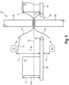
- the welding device has a heatable welding wheel for welding the paper webs and a pressing assembly for supporting the paper webs against the welding wheel
- the pressing assembly has at least one pressing wheel, in particular exactly two pressing wheels
- the welding wheel is adjustable between a working position in which the pressing assembly rests on the welding wheel and a rest position in which the welding wheel is spaced from the pressing assembly
- the welding device has at least one pre-tensioning element which pre-tensions the welding wheel into the rest position, wherein the paper webs lying on top of one another rest on the welding wheel in a contact area in the working position, wherein exactly two Pressure wheels are provided for supporting the paper webs against
- paper web is understood here to mean a packaging material layer made of paper, although this can also be paper-like material made of materials other than wood-based fibers, but which has properties suitable for packaging, such as strength, foldability or the like. In principle, however, hybrid packaging materials (e.g. paper/plastic composites or the like) are also included. It goes without saying that the upper and lower paper webs are each at least partially coated on the inner surfaces facing each other in order to prevent thermal To enable sealing or welding of the paper webs lying on top of each other.
- endless element is understood here to mean a self-contained, particularly belt-shaped, drive element for conveying paper webs, which can be designed as a belt, chain and/or the like. Such endless elements are particularly suitable for conveying paper webs due to the flat load distribution.
- paper web level is understood here to mean the level in which the upper paper web and the lower paper web converge and are transported and processed by the packaging machine.
- the paper web level can, for example, be the level in which the transport device for transporting the packaged goods is arranged, but the paper web level can also be provided, for example, at approximately half the height of the packaged goods.
- excessive heat input from the heated welding wheel onto the paper webs which can occur, for example, when the paper web sections are at a standstill in the longitudinal cutting and welding devices, can be avoided by using the pre-tensioning element.
- a standstill of the paper web sections can be intentional, for example in cyclic packaging machines.
- a paper web standstill can also occur due to a general machine standstill, whether intentional or unintentional due to a power failure or similar. Even if the heating of the cutting and sealing device is then also switched off, if the welding wheels cool down relatively quickly, the paper web sections located near the welding wheels can be subject to undesirable thermal deformation due to the large amount of heat input.
- contact area is understood here to mean the area in which the paper webs lying on top of each other touch or rest against the respective welding wheel. In a sense, this is a common contact section between the corresponding welding wheel and the paper webs lying on top of each other.
- the contact area can be linear or flat, for example.
- a flat contact area is preferable to a linear contact area, since the heat transfer distance of the paper web sections to be welded is increased in the flat contact area. The shorter the heat transfer distance, the hotter the welding wheel must be to seal the paper webs.
- the two pressure wheels of the respective welding device are spaced apart from each other and lie on the same side of the paper web, namely both on the side opposite the welding wheel.
- a longitudinal separation welding system is provided with a first and a second longitudinal separation welding device for welding the paper webs parallel to the transport direction on two opposite longitudinal sides of the paper webs, wherein both the first longitudinal separation welding device and the second longitudinal separation welding device is a longitudinal separation welding device according to the first aspect of the invention or one of its embodiments, wherein the first and the second longitudinal separation welding device each have at least the first pair of rotating endless elements which pull the first and the second paper web between them on the two opposite longitudinal sides of the paper webs and guide them in a paper web plane.
- a packaging machine for packaging a packaged product with an outer packaging produced from an upper paper web and a lower paper web, wherein the packaging machine has a longitudinal separation and welding system according to the invention.
- a method for longitudinally separating and welding an upper and a lower paper web comprising the steps of providing a longitudinal separating and welding device which has at least a first pair of circulating endless elements which pull the upper and the lower paper web between them and guide them in a paper web plane, wherein the longitudinal separating and welding device has a welding device, wherein the welding device has a heatable welding wheel for welding the paper webs and a pressing assembly for supporting the paper webs against the welding wheel, wherein the pressing assembly has at least one pressing wheel, in particular exactly two pressing wheels, wherein the welding wheel is adjustable between a working position in which the pressing assembly rests on the welding wheel and a rest position in which the welding wheel is spaced apart from the pressing assembly, wherein the paper webs lying on top of one another rest on the welding wheel in a contact area in the working position, wherein exactly two pressing wheels are provided for supporting the paper webs against the welding wheel, wherein the two pressing wheels are spaced apart from one another in are spaced apart from
- the paper webs lying on top of one another are spaced apart from both the welding knife and the pressing assembly in the rest position.
- the respective welding wheel is preferably arranged outside of the immediate vicinity, i.e. the area in which the paper webs or paper web sections are still welded despite the distance to the welding wheel, for example as a result of heat radiation, in order to avoid further heat input from the welding wheel onto the paper when the machine is at a standstill.
- the welding wheel and the at least one pressure wheel of the pressure assembly are driven jointly or are arranged to run freely.
- the welding wheel is designed as a rotating, heatable welding wheel.
- the at least one pressure wheel is also designed to rotate.
- the longitudinal separation welding device has a plurality of welding devices, each of which has at least one pre-tensioning element or has a common pre-tensioning element.
- the welding devices can each have a separate pre-tensioning element. However, they can also be pre-tensioned together in the rest position.
- the welding wheel is adjustable between the working position and the rest position orthogonal to the paper web plane.
- the welding wheel is height-adjustable.
- the height adjustment can be made, for example, along a vertical axis, i.e. parallel to a normal vector of the paper web plane. In this way, when the pairs of endless elements of the longitudinal cutting welding devices are stationary, the hot welding wheel can be moved away from the paper webs as quickly as possible.
- a rotation axis of the welding wheel is parallel to a rotation axis of the at least one pressure wheel of the pressure assembly, wherein the rotation axis of the at least one pressure wheel lies within a width of the projection of the welding wheel onto the paper web plane.
- the contact area is located, in particular centrally, between the two pressure wheels.
- An advantage of this design is that a symmetrical contact area and thus a symmetrical force distribution is established with respect to a center plane of the respective welding wheel, which is aligned orthogonally to the paper web plane and contains the rotation axis of the welding wheel.
- the contact area is shifted closer to one of the two pressure wheels (e.g. to the pressure wheel upstream of the center plane or to the pressure wheel downstream of the center plane).
- the two pressure wheels have the same diameter.
- the welding wheel is arranged above the paper web plane, and that an outer circumference of the welding wheel extends below a plane which rests on the highest points of the two pressure wheels of the pressure assembly.
- highest point can be understood here as the point on the outer circumference of each pressure wheel that has the minimum distance to the lower paper web in the rest position.
- the welding wheel is arranged below the paper web plane, and that an outer circumference of the welding wheel extends over a plane which rests against the lowest points of the pressure wheels of the pressure assembly.
- lowest point can be understood here as the point on the outer circumference of each pressure wheel that has the minimum distance to the upper paper web in the rest position.
- the respective welding device is arranged in the transport direction in front of the first pairs of endless elements of the longitudinal separation welding devices.
- each longitudinal cutting and welding device further comprises a longitudinal cutting device for cutting the paper webs lying on top of one another parallel to the transport direction on two opposite longitudinal sides, wherein the longitudinal cutting device comprises a rotating circular knife and a support wheel arranged opposite to the paper web plane for supporting the paper webs against the circular knife, wherein the circular knife and the support wheel extend in a circular knife plane which is arranged parallel to the transport direction, and that the first pair of endless elements of the respective longitudinal cutting and welding device rotate in a first circumferential plane, wherein the first circumferential plane and the circular knife plane each run perpendicular to the paper web plane, wherein the first circumferential plane and the circular knife plane are arranged parallel to one another.
- the proposed arrangement provides that a rolling direction of the respective circular knife is arranged parallel to the first pairs of endless elements of the longitudinal cutting and welding devices, and in particular parallel to the transport direction.
- the paper webs lying on top of one another are arranged between the rotating circular knife and the corresponding support wheel.
- the rotating circular knife is preferably an unheated, mechanical cutting element. This eliminates the need to decouple the circular knife from the paper webs as a result of a power failure in the machine or a standstill of the paper webs.
- the circular blades and the support wheels are driven, for example, by means of the second drive device.
- a drive device that is different from the second drive device is also conceivable.
- first and the second longitudinal cutting and welding device further each have at least a second pair of rotating endless elements which pull the paper webs lying on top of each other between them on the two opposite longitudinal sides of the paper webs and guide them in the paper web plane, wherein the circular blades are arranged in the paper web plane orthogonal to the transport direction between the first pair of endless elements of the respective longitudinal cutting and welding device and the second pair of endless elements of the same longitudinal cutting and welding device.
- the circular knife is arranged between the first pair of endless elements and the second pair of endless elements in such a way that the paper webs are guided by the first and second pair of endless elements on the side of the circular knife facing the packaged goods and on the opposite side of the circular knife facing away from the packaged goods in the transport direction.
- the second pair of endless elements of the longitudinal cutting welding devices each rotate in a second plane of rotation, wherein the second plane of rotation runs parallel to the circular blade plane.
- parallel guidance of the paper webs using spaced-apart endless element pairs in the respective longitudinal cutting and welding device is preferable to guidance of the paper webs inclined transversely outwards.
- the parallel guidance can prevent possible crack propagation upstream of the respective longitudinal separating device, which can otherwise occur due to the transverse tightening, can be avoided.
- the second circulation plane is inclined relative to the circular knife plane in order to separate any lateral paper overhang.
- the first and the second longitudinal separation welding device each have a pair of rollers arranged downstream of the second pairs of endless elements in the transport direction, wherein the respective pair of rollers of the longitudinal separation welding devices is designed to pull the two paper webs between them and to guide them in the paper web plane, wherein the rollers of the respective pair of rollers run outwards relative to the transport direction at a pre-tensioning roller angle, in particular such that a paper overhang laterally separated by means of the longitudinal separation device is transported away by the pair of rollers of the respective longitudinal separation welding device.
- the second drive device is designed to drive the first pair of endless elements and the second pair of endless elements together.
- control of the longitudinal cutting welding devices can be simplified compared to driving them separately.
- a conveying speed of the second pairs of endless elements corresponds to the conveying speed of the first pairs of endless elements.
- the longitudinal cutting device is arranged downstream of the respective welding device in the transport direction.
- the paper webs lying on top of one another are first welded lengthwise in the transport direction and then fed to the longitudinal cutting device for cutting the paper web areas lying on top of one another parallel to the transport direction on two opposite long sides of the outer packaging.
- the longitudinal cutting devices it is also possible to arrange the longitudinal cutting devices next to or upstream of the welding devices in the transport direction.
- the packaged goods are packaged in an outer packaging.
- the outer packaging is produced from an upper and a lower paper web.
- the packaged goods are arranged between the upper and lower paper webs.
- the upper and lower paper webs are thus arranged on opposite sides of the packaged goods.
- the pairs of endless elements of the feed devices are also operated at a conveying speed that differs from a conveying speed of the pairs of endless elements of the longitudinal cutting and welding devices.
- the packaging machine further comprises a control device which is designed to control the first and the second drive device independently of one another.
- the first drive device for driving the pairs of endless elements of the feed devices and the second drive device for driving the first pairs of endless elements of the longitudinal separation and welding devices are controlled independently of one another or separately.
- a conveying speed of the paper webs in the respective feed device can be achieved independently of a conveying speed of the paper webs in the respective longitudinal separation and welding device.
- the second drive device is different from the first drive device, wherein the first drive device has a first motor and the second drive device has a second motor, wherein the second motor is different from the first motor, and wherein the control device controls the first and the second motor.
- the first drive device for driving the pairs of endless elements of the feeding devices and the second drive device for driving the first pairs of endless elements of the longitudinal separation and welding devices are controlled separately by means of two mutually independent motors.
- controlling two mutually different motors is preferable due to the lower complexity.
- the motor can be an electric motor.
- pneumatic, hydraulic, magnetic or other motors are also conceivable.
- control device is further designed to control the first and to control the second drive device such that the pairs of endless elements of the feeding devices are driven at a first conveying speed and the first pairs of endless elements of the longitudinal cutting and welding devices are driven at a second conveying speed, wherein the first conveying speed differs from the second conveying speed.
- conveying speed can be understood here as the rotational or circumferential speed of the corresponding endless element. This rotational speed is transferred equally to the respective paper web, assuming a slip-free conveying process, so that different conveying speeds between the pairs of endless elements in the transport direction result in different speeds of the paper webs. In other words, this can cause the paper webs to be compressed or tightened in the transport direction.
- the first conveying speed of the pairs of endless elements of the feeding devices is greater than zero and the second conveying speed of the first pairs of endless elements of the longitudinal cutting and welding devices is equal to zero.
- cross-cutting and welding devices have an upper punch and a lower punch that move towards each other so that they meet in the film web plane (in this case the paper web plane) and separate and weld the films (in this case the paper webs).
- a cross-cutting and welding device is described, for example, in the publication EN 10 2017 131 026 A1 shown.
- closed cross-cutting welding device is not restricted in the present case to a state in which the upper and lower punches are in contact with one another in the plane of the paper web and clamp the paper webs between them, but also includes states in which the upper and lower punches are moving towards one another but are not yet arranged in the plane of the paper web.
- a first conveying speed of the pairs of endless elements in the feed devices is set that is greater than zero, while the first pairs of endless elements of the longitudinal cutting welding devices "stand still". Accordingly, the paper webs lying on top of one another, which are clamped between the respective first pair of endless elements of the longitudinal cutting welding devices in the paper web plane, also stop. Since the cross-cutting welding device is arranged between the feed devices and the longitudinal cutting welding devices in the transport direction, paper is pushed or fed upstream of the cross-cutting welding device. The paper webs are consequently relaxed in the transport direction, which can ensure crack-free cross-cutting welding of the paper webs.
- the second conveying speed of the first pairs of endless elements of the longitudinal cutting and welding devices is greater than the first conveying speed of the pairs of endless elements of the feeding devices, wherein the first conveying speed of the pairs of endless elements of the feeding devices is greater than zero.
- open cross-cutting welding device can be understood here as a state in which an upper and lower punch of the cross-cutting welding device are spaced apart from one another in such a way that they do not lie against one another in the plane of the paper web. In other words, in this open state, the paper webs do not lie against the upper and lower punches, which corresponds to continuous operation.
- a first conveying speed of the pairs of endless elements in the feed devices is set, which is greater than zero, while the first pairs of endless elements of the longitudinal cutting and welding devices are driven at a second speed, which in turn is greater than the first conveying speed.
- first endless element and the second endless element of the pair of endless elements of the respective feed device are inclined towards each other in the transport direction.
- the packaged goods In known series packaging machines, it is usual for the packaged goods to be arranged between the upper and lower film or paper webs.
- the upper and lower paper webs are thus arranged on opposite sides of the packaged goods.
- the upper and lower paper webs also run towards each other downstream due to the relative inclination of the first and second endless elements in the transport direction.
- the angle of inclination between the first and second endless elements of the pairs of endless elements of the respective feed device is preferably constant.
- the term "inclined towards each other" is therefore to be understood as meaning that the vertical distance between the endless elements from each other decreases in the transport direction.
- the pairs of endless elements of the feeding devices are jointly height-adjustable.
- the packaging machine can also take into account and process packaged items of different heights.
- the height adjustment of the feed devices can basically be carried out manually, e.g. by means of an actuatable crank element, or automatically or motor-driven.
- the height of the item to be packaged can also be adjusted for this purpose.
- the packaged goods can be detected by suitable sensors in order to further increase the precision of the height adjustment.
- the cross-cutting welding device can of course also be designed to be height-adjustable.
- the cross-cutting welding device can also be designed to adjust only the cutting welding level at which the upper and lower stamps meet.
- the longitudinal cutting welding devices can also be designed to be height-adjustable for this purpose.
- control device is designed to control the first drive device in such a way that the first conveying speed or a conveying period of the pairs of endless elements of the feed devices is adapted to a height adjustment or height setting of the feed devices when the second conveying speed is zero. This makes it possible to avoid a collision of the upper or lower paper web with the transport device.
- the pairs of endless elements of the feed devices are jointly height-adjustable in order to be able to handle different heights of packaged goods. Since the angle of inclination between the first and the second endless element is preferably constant, there is a high degree of flexibility as a result of the height adjustment of the feed devices, e.g. a first packaged product onto a higher second packaged product, and the associated height shift of the paper web level, the risk of a collision between the lower paper web and an edge of the first of the two consecutive transport devices. In order to avoid such a collision, according to the invention the first conveying speed or the conveying period of the pairs of endless elements of the feed devices is adjusted, in the present example increased.
- the lower paper web can be relaxed in the transport direction and accelerated relative to the previous state. In this way, the lower paper web can be guided around the edge. Furthermore, the "pushing" by means of the feed device provides the lower and upper paper webs with enough play so that the paper webs can wrap around the packaged product and closing the cross-cutting welding device does not tear any of the paper webs.
- the pair of endless elements of the first and the second feed device each rotate in a plane of rotation, wherein the planes of rotation of the pairs of endless elements each run perpendicular to the paper web plane and define a distance between them, in particular orthogonal to the transport direction.
- the proposed arrangement provides that the plane of rotation of the pair of endless elements of the first feed device and the plane of rotation of the pair of endless elements of the second feed device are aligned parallel to one another and parallel to the transport direction, with the respective plane forming a right angle with the paper web plane. A width or a distance is therefore defined between the planes.
- a distance perpendicular to the transport direction between the pairs of endless elements of the feeding devices is adjustable.
- the packaging machine according to the invention is width-adjustable, so that the width of the outer packaging can be adapted to packaged goods of different shapes and widths. can be adjusted.
- the width between the two levels can be adjustable, for example, by means of a spindle that extends between the first and second feed device. Such a spindle can also be coupled very easily to the first drive device by means of an endless element. Alternatively, however, it is also possible to adjust the width between the levels by means of a crank element.
- the at least one pair of circulating endless elements for conveying the paper webs runs over at least two rollers each, wherein the first and the second feed device further each have a first conveyor element and a second conveyor element, wherein the first conveyor elements and the first endless elements of the pairs of endless elements of the feed devices pull the upper paper web between them on two longitudinal sides of the upper paper web that are opposite with respect to the transport direction, in particular and guide it in an upper paper web plane, and wherein the second conveyor elements and the second endless elements of the pairs of endless elements of the feed devices pull the lower paper web between them on two longitudinal sides of the lower paper web that are opposite with respect to the transport direction, in particular and guide it in a lower paper web plane.
- the proposed arrangement does not provide for the driven pairs of endless elements of the feed devices to clamp and guide the upper paper web and the lower paper web between them, but rather for a complementary conveying element to be provided for each endless element of the feed devices.
- the conveying elements are preferably not driven.
- the first conveying element is designed as a first roller arrangement with at least two rollers for guiding the upper paper web
- the second conveying element is designed as a second roller arrangement with at least two rollers for guiding the lower paper web.
- roller arrangements instead of additional counter-endless elements enables a simpler and more compact design of the feeding devices.
- a rolling direction of the rollers of the first roller arrangement of the respective feed device and a rolling direction of the rollers of the second roller arrangement of the respective feed device each run outwards at a roller angle relative to the transport direction.
- the inclined position of the rollers of the first roller arrangement according to the invention results in transverse tightening of the upper paper web
- the inclined position of the rollers of the second roller arrangement results in transverse tightening of the lower paper web.
- the rollers of the respective roller arrangement can be coated to ensure that the paper webs are gripped and held in a non-slip manner. If, for example, the endless element has a rubberized surface, it can be advantageous to make the surface of the complementary rollers knurled to ensure that the applied transverse force does not cause the paper webs to slip between the conveyor elements and the endless elements.
- the first and the second feed device each have at least one pair of rollers arranged in the transport direction between the pairs of endless elements and the cross-cutting welding device on the opposite longitudinal sides of the paper webs, wherein a first roller and a second roller of the respective pair of rollers are arranged on two opposite sides of the paper webs lying on top of one another with respect to the paper web plane.
- a pair of rollers arranged in this way improves the feeding of the upper paper web and the lower paper web into the cross-cutting welding device and thus enables a better quality cross-cutting welding of the paper webs.
- this ensures that the cross-cutting welding device, or its upper punch and lower punch, welds the upper paper web and the lower paper web while the latter runs essentially horizontally and in the paper web plane.
- the first roll of the roll pair can be arranged above the paper web plane and the second roll of the roll pair can be arranged below the paper web plane, or vice versa.
- the first roller and the second roller of the respective roller pair pull the upper paper web and the lower paper web between them and guide them in the paper web plane.
- an unwinding direction of the roller pair of the respective feed device is aligned parallel to the transport direction.
- the proposed arrangement provides that the rotation axes of the rollers of the respective roller pair are aligned parallel to the paper web plane and orthogonal to the transport direction.
- the unwinding direction of at least one roller of the roller pair of the respective feed device runs outwards at a pre-tension roller angle relative to the transport direction.
- Such a pre-tensioning system can achieve a certain transverse tightening of the paper webs before they enter the transverse or longitudinal cutting and welding device.
- an unwinding direction of the first roller of the respective roller pair is aligned parallel to the transport direction, whereas an unwinding direction of the second roller runs outwards at a pre-tension roller angle relative to the transport direction.
- both rollers of the respective roller pair can also run outwards at a pre-tension roller angle relative to the transport direction.
- one roller of the respective roller pair can, for example, have a rubberized surface, whereas the other roller the same pair of rollers can, for example, have a knurled surface, which is preferably made of a metal.
- the cross-cutting welding device has a first stamp and a second stamp, wherein the first stamp has two heating devices spaced apart from one another by a first gap, the surfaces of which facing the second stamp each form a cross-welding surface, wherein the cross-welding surfaces lie in a common welding surface plane parallel to the paper web plane, wherein the second stamp has two pressure-absorbing devices spaced apart from one another by a second gap, wherein the pressure-absorbing devices form a support surface facing the first stamp, wherein the second stamp has a separating knife arranged in the second gap, wherein the first gap of the first stamp is arranged opposite the second gap of the second stamp, wherein the first and second stamps are movable relative to one another orthogonally to the paper web plane.
- the first stamp can be the upper stamp or the lower stamp and the second stamp can be the other of the upper stamp and the lower stamp. Preferably, however, the first stamp is the upper stamp and the second stamp is the lower stamp.
- Each of the pressure-receiving devices in the second stamp can be mounted so that it can move parallel to the separation gap plane, in particular spring-loaded.
- the separating knife is then mounted firmly in the second stamp.
- the separating knife cannot be moved in the second stamp.
- the pressure-receiving devices thus move relative to the separating knife when force is applied against the spring force of their spring-loaded mounting in the separation welding plane.
- each of the pressure-receiving devices in the second stamp is mounted so that it is fixed parallel to the separation gap plane.
- the separating knife is then mounted so that it can move in the second stamp.
- the separating knife can be moved in the second stamp, for example by means of an actuating device. This can be a pneumatic actuating device.
- the movement of the separating knife can be actively controlled, for example via the control device of the packaging machine.
- the cutting knife thus emerges from the second gap either due to the spring-loaded mounting or the movement by means of the actuating device and into the opposite first gap of the first stamp.
- the paper webs are not cut across the entire width of the paper webs lying on top of each other.
- the cutting preferably takes place in such a way that a continuous strip remains on both sides of the paper webs, which is used to convey through the longitudinal cutting and welding devices and is preferably only cut off in the longitudinal cutting device.
- the first stamp and the second stamp are movable relative to one another orthogonally to the paper web plane in such a way that the transverse welding surface arranged upstream in the transport direction and the pressure receiving device arranged upstream in the transport direction abut one another, and that the transverse welding surface arranged downstream in the transport direction and the pressure receiving device arranged downstream in the transport direction abut one another.
- the pressure absorption devices are each subjected to a force by the two heating devices. In the case of the spring-loaded mounting, this acts against the spring force of their spring-loaded mounting. In this way, it can be ensured that the film webs are mechanically severed by means of the cutting knife and, in particular, thermally sealed or welded together at the same time.
- the pressure-receiving devices are spring-mounted in the second stamp in such a way that the separating knife is arranged retracted into the support surface when the support surface and the transverse welding surfaces are spaced apart from one another, and that the separating knife protrudes from the support surface and protrudes into the first gap when the transverse welding surfaces each apply a sealing force to the support surface.
- the packaging machine further comprises at least one upper unwinding roller carrying the upper paper web and at least one lower unwinding roller carrying the lower paper web, in particular wherein the upper and lower unwinding rollers can each be braked.
- the packaging machine further comprises an adjustable pendulum roller assembly for guiding each of the upper and lower paper webs.
- the pendulum assembly preferably has a number of upper deflection rollers arranged perpendicular to the transport direction and a number of lower deflection rollers arranged perpendicular to the transport direction.
- the upper and lower paper webs are each guided alternately between the pendulum assembly and a complementary counter-roller assembly, which is also arranged perpendicular to the transport direction.
- the pendulum assembly is adjustable relative to the counter-roller assembly. In this way, the respective paper web can be tightened and smoothed, for example when the machine is at a standstill.
- the pendulum roller assembly can be manually or motor-driven.
- the packaging machine further comprises at least one upper feed roller pair and/or at least one upper feed roller for unwinding the upper paper web from the upper unwind roller and at least one lower feed roller pair and/or at least one lower feed roller for unwinding the lower paper web from the lower unwind roller, wherein the upper and lower feed roller pairs are arranged in the transport direction between the pendulum roller assembly and the feed devices.
- an unwinding direction of the feed roller pairs is arranged parallel to the transport direction.
- the feed rollers of the upper feed roller pair are designed to draw in and guide the upper paper web between them.
- the feed rollers of the lower roller pair are designed to draw in and guide the lower paper web between them.
- the feed rollers preferably extend over the entire width of the respective paper web.
- the packaging machine further comprises a third drive device for driving the upper and lower feed roller pairs and/or the at least one upper and lower feed roller.
- control device is further designed to control the third drive device independently of the first and the second drive device.
- control device is designed to control the third drive device in such a way that the feed roller pairs are driven at a third conveying speed.
- a feed speed or conveying speed of the respective paper webs in continuous operation gradually increases from the unwinding rollers to the longitudinal cutting welding devices downstream in the transport direction.
- a further advantage of this design is that, for example, when the cross-cutting welding device is closed, the first and third drive devices can be driven without the second drive device being driven. In this way, as explained above, paper can be fed upstream of the cross-cutting welding device.
- the third drive device has a third motor.
- the third motor is preferably different from the first and the second motor.
- the control device can be designed in particular to control the third motor, the first motor and the second motor. It can be provided in particular that the third drive device has a third motor, wherein the third motor is different from the first and the second motor.
- the welding wheel is pre-tensioned into the rest position by means of a pre-tensioning element, and wherein the welding wheel is moved into the working position by means of an adjusting device against a force of the pre-tensioning element.
- the design of the adjustment device and the pre-tensioning element can be suitably selected.
- a mechanical implementation can be selected in which the pre-tensioning element is a spring element and the adjustment device is an actuator, for example pneumatically operated.
- An electromagnetic design can also be selected in which the pre-tensioning element is provided by permanent magnets and the adjustment device by an electromagnet or a coil that can be charged with current.
- a combination of these elements can also be selected, i.e. a combination of mechanical and electromagnetic elements.
- the welding wheel is pre-tensioned into the rest position by means of the pre-tensioning element. This means that, for example, in the event of a power failure, the welding wheel automatically jumps into the rest position.
- the paper webs are separated parallel to a conveying direction of the paper webs by the at least one first pair of circulating endless elements.
- the separation takes place by means of a rotating separating knife, in particular wherein the rotating separating knife is driven by the same drive device as the at least one first pair of rotating endless elements.
- the packaging machine has a transport device for transporting a packaged product in a transport direction, a cross-cutting welding device for welding an upper and a lower paper web transversely to the transport direction, a first and a second feed device for feeding the paper webs into the cross-cutting welding device, wherein the first and the second feed device each have at least one pair of circulating, in particular running over at least two rollers, endless elements for conveying the paper webs, wherein a first endless element of the pair of endless elements is designed to convey the upper paper web and a second endless element of the pair of Endless elements for conveying the second paper web, a first and a second longitudinal separation welding device for welding the paper webs parallel to the transport direction on two opposite longitudinal sides of the paper webs, wherein each of the first and the second longitudinal separation welding device has at least a first pair of rotating endless elements, in particular running over at least two rollers each, which pull the first and the second paper web between them on
- the first conveying speed of the pairs of endless elements of the feeding devices is greater than zero and the second conveying speed of the first pairs of endless elements of the longitudinal cutting welding devices is equal to zero.
- the longitudinal cutting welding device does not feed the paper webs any further.
- the pairs of endless elements of the feed devices continue to push the paper webs forward while the stamps of the cross-cut welding device move together. This prevents the paper webs from tearing during the cross-cut welding process.
- the second conveying speed of the first pairs of endless elements of the longitudinal cutting welding devices is greater than the first conveying speed of the pairs of endless elements of the feeding devices, wherein the first conveying speed of the pairs of endless elements of the feeding devices is greater than zero.
- This setting can be made especially if the maximum height of the packaged goods needs to be changed. However, it is also possible to make the height adjustment if the height of the packaged goods changes between successive packages.
- the first conveying speed of the pairs of endless elements of the feed devices is increased when the height of the packaged goods between the two consecutive packaged goods increases or when a larger maximum packaged goods height is set.
- the period over which the first conveying speed of the pairs of endless elements of the feed devices is greater than zero and the second conveying speed of the first pairs of endless elements of the longitudinal cutting and welding devices is zero can also be increased at a constant speed.
- the paper webs are then also pushed forward a longer distance when the longitudinal cutting and welding device no longer conveys the paper webs.
- the first conveying speed of the pairs of endless elements of the feed devices is reduced when the height of the packaged goods between the two consecutive packaged goods or if a smaller maximum packaged goods height is set.
- the period over which the first conveying speed of the pairs of endless elements of the feed devices is greater than zero and the second conveying speed of the first pairs of endless elements of the longitudinal cutting and welding devices is zero can be reduced.
- the paper webs are then also pushed forward a shorter distance when the longitudinal cutting and welding device no longer conveys the paper webs.
- the first and the second longitudinal separation welding device each have at least one welding device with a heatable welding wheel for welding the paper webs and a pressing assembly for supporting the paper webs against the welding wheel, wherein the welding wheel is adjustable between a working position in which the pressing assembly rests on the welding wheel and a rest position in which the welding wheel is spaced apart from the pressing assembly, wherein the welding wheel is moved from the working position to the rest position as soon as conveying of the paper webs in the longitudinal separation welding devices has been stopped, and wherein the welding wheel is moved again to the working position before the paper webs are conveyed again by the longitudinal separation welding devices.
- the packaging machine further comprises at least one upper feed roller pair for unwinding the upper paper web from an upper unwinding roller and at least one lower feed roller pair for unwinding the lower paper web from a lower unwinding roller, wherein the upper paper web and the lower paper web is conveyed into the feeding devices by means of the feed roller pairs, wherein the feed roller pairs are driven at a third speed which is lower than the first conveying speed of the pairs of endless elements of the feeding devices.
- the packaging machine can provide at least three speed levels that increase in the transport direction so that the paper webs are conveyed in a streamlined manner through the entire packaging machine.
- first and the second longitudinal separation welding device further each have at least a second pair of endless elements running over at least two rollers each for guiding the paper webs in the paper web plane, wherein the second pairs of endless elements of the feed devices are driven at the second conveying speed of the first pairs of endless elements of the longitudinal separation welding devices.
- the paper webs can be pulled through the longitudinal cutting and welding device at the highest speed.
- the endless elements also allow the paper webs to be driven without damaging them.
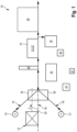
- Fig.1 shows a packaging machine 10 in a schematic view.
- the packaging machine 10 serves to provide a packaged item 12 with an outer packaging.
- the packaged item 12 is transported in a transport direction T through the packaging machine 10.
- the packaging machine 10 wraps the goods to be packaged with an upper paper web 14, which is unwound from an upper supply or unwinding roll 15, and a lower paper web 16, which is unwound from a lower supply or unwinding roll 17. This type of wrapping corresponds to the principle of the series packaging machine.
- the upper paper web 14 and the lower paper web 16 are fed by means of a first feed device 18 and a second feed device 18'.
- the upper paper web 14 and the lower paper web 16 converge in a paper web plane 19 in which they are conveyed and processed by the packaging machine 10.
- the paper webs 14, 16 are preferably inclined towards one another.
- the paper web plane 19 can be the plane in which, for example, a transport device for transporting the packaged goods is arranged.
- the paper web plane can also be provided, for example, at approximately half the height of the packaged goods 12, as shown with a paper web plane 19'.
- the height of the paper web plane 19 can be adjustable.
- the packaged goods 12 thus move into the upper paper web 14 and lower paper web 16 which converge towards one another.
- the wrapped packaged goods 12 reach a cross-cutting welding device 20.
- the cross-cutting welding device 20 closes the paper webs 14, 16 together transversely to the transport direction and cuts the paper webs 14, 16 at least partially, so that the packaged goods 12 no longer have any contact with the packaged goods 12 preceding it along the weld seam.
- the packaged goods 12 then travel through a first longitudinal cutting welding device 22 and a second longitudinal cutting welding device 22', which are designed to weld the paper webs 14, 16 together on opposite sides of the paper webs parallel to the transport direction T to the side of the packaged goods 12 and to cut off any lateral paper overhang of the paper webs 14, 16.
- the first longitudinal cutting welding device 22 and a second longitudinal cutting welding device 22' form a longitudinal cutting welding system 21.
- the side of the packaged goods facing opposite to the transport direction T is also welded and trimmed by the transverse cutting welding device 20.
- the packaged goods 12 are now welded and trimmed on all four sides, so that the packaged goods 12 are completely surrounded by a paper wrapping.
- the packaging machine 10 has a first drive device 24 for driving the first feed device 18 and the second feed device 18'.
- the packaging machine 10 has a second drive device 26 for driving the first longitudinal separation and welding device 22 and the second longitudinal separation and welding device 22'.
- the packaging machine 10 can have a control device 27.
- the control device 27 is preferably designed to control the first drive device 24 and/or the second drive device 26.
- the sequence of the transverse cutting welding device 20 and the longitudinal cutting welding devices 22, 22' is shown only as an example in a preferred configuration.
- the sequence of these devices can also be different, for example it can be provided that the transverse cutting welding device 20 is arranged after the longitudinal cutting welding devices 22, 22'.
- At least one further module 28 is connected, which processes the welded paper webs 14, 16.
- a labeler can be provided (not shown), which applies a label to at least one of the paper webs 14, 16.
- a A separation station can be provided which cuts off any excess paper remaining after passing through the longitudinal separation and welding devices 22, 22' in the longitudinal direction, closely fitting the packaged goods, and then welds it again. This can be provided in particular for packaged goods with varying widths.
- a paper return 30 can also be provided which serves to collect the excess paper cut off in the longitudinal separation and welding devices 22, 22' so that it can be recycled.
- the packaging machine 10 has adjustment devices 32 which serve to adjust the packaging machine 10 to a height and a width of the packaged goods 12. Possible configurations of the feed devices 18, 18', the transverse cutting and welding device 20 and the longitudinal cutting and welding devices 22, 22' are explained in more detail with reference to the figures.
- Fig. 2 shows a side view of an embodiment of a feeding device 18. The side of the feeding device 18 facing the packaged goods 12 is shown.
- the first feed device 18 and the second feed device 18' are arranged opposite one another with respect to the transport direction T.
- the design of the feed devices 18, 18' explained below is based only on the feed device 18, but essentially also applies to the other of the two feed devices 18, 18'.
- a pair of endless elements 34 is provided in the feed device 18, 18'.
- the pair of endless elements 34 in the present case has an upper endless element 34 ⁇ and a lower endless element 34".
- the upper endless element 34 ⁇ runs around two rollers 36, 38.
- the lower endless element 34" runs around two rollers 40, 42.
- the feed device 18, 18' has a first conveying element 44 and a second conveying element 46.
- the upper endless element 34' and the first conveying element 44 are arranged on two opposite sides of the upper paper web 14 with respect to the upper paper web 14. arranged and pull the upper paper web 14 between them and feed it to the paper web plane 19, 19'.
- the lower endless element 34" and the second conveyor element 46 are arranged on two opposite sides of the lower paper web 16 with respect to the lower paper web 16 and pull the lower paper web 16 between them and feed it to the paper web plane 19, 19'.
- the first conveyor element 44 is designed as a roller arrangement with three rollers 44-1, 44-2 and 44-3.
- the second conveyor element 46 is designed as a roller arrangement with three rollers 46-1, 46-2 and 46-3. As the Fig. 2 As can be seen, the pair of endless elements 34 can be inclined towards each other.
- the Fig. 2 a motor 48 for driving the pair of endless elements 34.
- the motor 48 is mounted, for example, on a holder 50 of the feed device 18 and drives a first drive element 54 via a first wheel mechanism 52.
- a second drive element 56 is also provided.
- the second drive element 56 is movable via a second wheel mechanism 58.
- the first wheel mechanism 52 and the second wheel mechanism 58 share a common deflection wheel 60.
- the first drive element 54 and the second drive element 56 are operatively connected to one another via the common deflection wheel 60.
- the second drive element 56 meshes with the roller 38 of the upper endless element 34 ⁇ and the roller 42 of the lower endless element 34". In this way, the movement variables of the motor (e.g. torque, speed or the like) can be transmitted to the second drive element 56.
- a pair of rollers 62 can be provided in the transport direction T downstream with respect to the pair of endless elements 34.
- the pair of rollers 62 has a first roller 62-1 and a second roller 62-2.
- the first roller 62-1 and the second roller 62-2 are designed to pull the supplied paper webs 14, 16 between them on a long side and to convey them in the paper web plane 19, 19'. It can be provided that the unwinding direction of the pair of rollers 62 is aligned parallel to the transport direction T. In Fig. 2 It can be seen that the first roller 62-1 and the second roller 62-2 of the roller pair 62 also mesh with the second drive element 56.
- Fig.3 shows a plan view of an embodiment of the feed devices 18, 18 ⁇ . Identical elements are provided with the same reference numerals and are not explained in more detail.
- the paper webs 14, 16 Before the paper webs 14, 16 are fed in the transport direction T to the cross-welding device 20, the paper webs 14, 16 can be subjected to a cross-tightening in the feed devices 18, 18'.
- an unrolling direction of the rollers 44-1, 44-2 and 44-3 of the first conveyor element 44 and an unrolling direction 68 of the rollers 46-1, 46-2 and 46-3 of the second conveyor element 46 each run outwards at a roller angle 70 relative to the transport direction T.
- an unrolling direction of the pair of endless elements 34 is aligned parallel to the transport direction T.
- first feed device 18 and the second feed device 18' are driven by a common motor 48.
- a shaft 64 extending between the first feed device 18 and the second feed device 18' can be provided.
- the shaft 64 is preferably aligned orthogonally to the transport direction T.
- the shaft 64 is connected at its two opposite ends in a rotationally fixed manner to a wheel 66, cf. Fig. 2 , of the first wheel mechanism 52. In this way, a rotary motion of the first drive element 52 of the first feed device 18 can be equally transmitted to a rotary motion of the first drive element 52 of the second feed device 18'.
- a rolling direction of the roller pair 36, 38 of the upper endless element 34' or the roller pair 40, 42 of the lower endless element 34" is designed parallel to the transport direction T.
- the endless elements 34' and 34" i.e. parallel to the transport direction, move.
- the unwinding direction of the non-driven rollers 44-1, 44-2 and 44-3 is, as stated above, inclined by the roller angle 70 relative to the transport direction T. In this way, good guidance and transverse tightening of the Paper webs are produced without putting too much strain on them and possibly tearing them. Migration of the paper webs 14, 16 is avoided because the unwinding directions 68 of the opposing rollers 44-1, 44-2 and 44-3 of the two feed devices 18, 18' point away from each other and outwards.
- the unwinding direction 68 of the first roller 62-1 and the second roller 62-3 is also parallel to the transport direction.
- the first roll 62-1 and the second roll 62-2 are arranged downstream between the respective upper and lower endless elements 34', 34" and the cross-cutting welding device.
- the first roll 62-1 and the second roll 62-3 pull the first and second paper webs between them. This takes place on both sides of the packaged goods 12.
- the paper webs 14, 16 are then guided together in the paper web plane 19 and are pulled into the respective longitudinal cutting welding device 22 or 22' after the cross-cutting welding device 20.
- two rails 72 and 72' are provided, each of which is assigned to a feed device.
- the respective rail 72, 72' is arranged inside, i.e. in the direction of the packaged goods, of the upper endless element 34' of the respective feed device 18, 18'.
- the upper paper web 14 can slide on these rails 72, 72' and is thereby kept slightly open inside, i.e. where the packaged goods 12 are arranged, in order to simplify the entry of the packaged goods 12 between the upper paper web 14 and the lower paper web 16.
- rollers 62-1 and 62-3 can be suitably designed to ensure good pulling in and guiding of the paper webs 14, 16.
- one of the rollers for example the roller 62-2, can be designed with a corrugated surface, the roller 62-1 or the other roller can be rubberized.
- Fig.5 is a schematic view explaining the feeding of the upper paper web 14 and the lower paper web 16.
- the packaged goods 12 run in the transport direction T on a conveyor belt 80.
- a downstream end of the conveyor belt 80 is designated by the reference numeral 82.
- the conveyor belt 80 and a subsequent conveyor belt 84 form a stamp gap between them, in which the transverse cutting and welding device 20 is arranged.
- An upper stamp 86 and a lower stamp 88 of the transverse cutting and welding device separate and weld the upper paper web 14 and the lower paper web 16 at the stamp gap.
- the stamp gap is generally designated by the reference numeral 85.
- the upper stamp 86 and the lower stamp 88 weld or seal the upper paper web 14 and the lower paper web 16 to one another and separate the two paper webs at least partially transversely to the transport direction T.
- the upper paper web 14 and the lower paper web 16 remain connected to one another only on their left and right sides and are thus drawn into the longitudinal cutting and welding device, as will be explained in more detail below.
- the packaged goods 12 have a height H. Half the height of the packaged goods 12 is designated H/2.
- the paper web plane 19 is marked by a dashed line.
- a height H max This is the maximum height of a packaged product 12 that can be processed. This height is the height of the upper endless element 34' above the conveyor belt 80. The lower endless element 34" is located below the conveyor belt 80. Half the height between the upper and the lower endless element, where the paper web level 19 is located, is thus below half the package height H/2.
- the first feed device 18 and the second feed device 18' are entirely adjustable in height.
- the upper endless element 34' and the lower endless element 34" are also adjustable in height together with the rail 72.
- the packaging machine can be set to a desired maximum packaged goods height H max .
- H max is adjustable between 0 and 100 mm.
- the cross-cutting welding device 20 is shown in a closed position. Since paper is a material that is not stretchable and tears when stretched to a high degree, the upper paper web 14 and the lower paper web 16 must be "pushed forward" when the cross-cutting welding device closes. Overall, the operation of the packaging machine 10 is cyclical. This means that when the cross-cutting welding device 20 is closed, the longitudinal cutting welding device stops, the speed of the second drive device 26 is then 0. However, the first drive device 24 of the feed devices 18 and 18' is not stopped immediately. This has the following reason.
- the points S and S' are in the Fig.5 These are the upper and lower points of an upstream side of the Fig.5 with the reference number 12'.
- the upper paper web 14 and the lower paper web 16 are welded together and separated in the paper web plane 19.
- the upper paper web 14 must therefore extend down the packaged goods 12' to the paper web plane 19.
- the upper and lower paper webs then run upstream between the upper punch 86 and the lower punch 88 and then to the respective upper endless element 34' or lower endless element 34".
- the upper paper web 14 and the lower paper web 16 do not run in a straight line between the upper endless element 34' and the point S or from the lower endless element 34" to the point S'. Outside of the On opposite sides of the paper webs 14, 16, the paper webs are guided by the rollers 62-1 and 62-2 in the paper web plane 19. In the middle, where the packaged goods 12 are located, as in the Fig.5 However, as shown, there must be a sufficient amount of paper or paper section of the upper paper web and the lower paper web 16 so that the paper webs 14, 16 can be folded together from the points S or S' into the paper web plane 19 and welded together there without the paper webs 14 and 16 tearing.
- the paper webs 14 and 16 must continue to be conveyed by the feed devices 18, 18' for a certain period of time.
- the period of time over which the feed devices 18 and 18' must continue to run or "push" depends on their conveying speed.
- the decisive factor is that a sufficient length of the upper paper web 14 and the lower paper web 16 is pushed forward. This depends on the height setting H max .
- the height setting H max changes the vertical distance between the points S and S'.
- a higher packaged item 12' naturally requires a larger amount of material so that the upper paper web 14 and the lower paper web 16 can be brought together on its upstream side.
- the height of the lower endless element 34" is brought closer to the conveyor belt 80.
- the upper stamp 86 and the lower stamp 88 will meet in the paper web plane 19, so that the lower paper web 16 runs around the end 82 due to its low tension. This is also schematically shown in the Fig.5 to be taken.
- the first drive device 24 and the second drive device 26 are provided, which can provide two separate conveying speeds independently of one another.
- the two drive devices 24 and 26 enable the upper paper web 14 and the lower paper web 16 to be conveyed through the packaging machine 10 at an increasing conveying speed in the transport direction, the conveying speed of the first drive device 24 or the feed devices 18, 18' corresponding to approximately 80% of the conveying speed of the longitudinal separation and welding devices 22, 22'.
- the extent of this "pushing" can be set and stored as a function of the height setting of the feed devices 18, 18', so that a height setting of the pocket formed by the upper paper web 14 and the lower paper web 16 and thus of the maximum packaged goods 12 can be set.
- the term "drive device” is to be understood independently of the number of motors and the mechanical coupling. As shown in the figures, one motor can be provided for the first drive device or the second drive device, which is then mechanically coupled to the feed devices 18, 18' or the longitudinal separation and welding devices 22, 22' on both sides. However, a plurality of motors can also be provided within each of the drive devices, with at least one motor being provided for each of the feed devices 18, 18' or longitudinal separation and welding devices 22, 22'. These must then be controlled in parallel.
- Fig.6 shows a side cross-sectional view through the cross-cutting welding device 20. Identical elements are marked with the same reference numerals and will not be explained again.
- the upper punch 86 and the lower punch 88 are each designed in two parts.
- the welding elements of the upper punch 86 form a welding surface plane 90 facing the lower punch 88.
- the corresponding elements of the lower punch 88 form a welding surface plane 91 facing the upper punch 86.
- the upper punch 86 has a first punch part 92 and a second punch part 94.
- a first heating cartridge 96 or another suitable heating device is arranged in the first punch part 92.
- a second heating cartridge 98 or another suitable heating device is arranged in the second punch part 94.
- the heating devices 96 and 98 can also be connected to one another or designed as one heating device.
- the first punch part 92 and the second punch part 94 are spaced apart from one another by a gap 95 in the transport direction. Their surfaces 93 and 93' facing the lower stamp 88 form the welding surface plane 90.
- the first and second stamp parts 92, 94 are heated to a temperature that enables the upper and lower paper webs 14, 16 to be welded together.
- the upper and lower paper webs 14, 16 are provided with a suitable coating on their surfaces facing one another, which weld or bond together when heated sufficiently.
- first counter-pressure element 106 and a second counter-pressure element 108 are pressed onto a first counter-pressure element 106 and a second counter-pressure element 108, respectively.
- the counter-pressure elements 106, 108 are provided on the lower punch 88 and form the welding surface plane 91 there. They are made of a temperature-resistant material, for example Teflon.
- the first counter-pressure element 106 is part of a first pressure-absorbing device 100 and the second counter-pressure element 108 is part of a second pressure-absorbing device 102.
- the pressure-absorbing devices 100, 102 each have a spring element 105, 105'. In this way, it is possible for the first counter-pressure element 106 and the second counter-pressure element 108 to deflect by a spring travel F.
- a separating knife 104 located in a gap 103, which is opposite the gap 95 across the paper web plane 19, can emerge.
- the first pressure receiving device 100 and the second pressure receiving device 102 are spaced apart by a gap 103.
- the separating knife 104 is fixed in the gap. If the first counter-pressure element 106 and the second counter-pressure element 108 spring in, the separating knife 104 passes through the welding surface plane 91 or the paper web plane 19 and into the gap 95.
- the separating knife can also be moved by means of an actuating device, which is designed pneumatically, for example.
- the pressure receiving devices 100, 102 can then be designed to be fixed. In this way, the upper paper web 14 and the lower paper web 16 can be cut or separated.
- the upper punch 86 and the lower punch 88 are then moved away from each other and the paper webs 14, 16 can continue to move in the transport direction T. In this way, a clocked cross-cut welding is implemented.
- the Fig.7 shows a side view of an embodiment of the longitudinal cutting welding device 22.
- the longitudinal separation welding device 22 has a structure that corresponds to that of the longitudinal separation welding device 22'.
- the longitudinal separation welding devices 22 and 22' then together form a longitudinal separation welding system 21.
- the longitudinal separation welding devices 22 and 22' are arranged opposite one another. They then weld two paper webs 14, 16 lying on top of one another on opposite sides of the paper webs 14, 16 or the packaging machine 10.
- the longitudinal cutting welding device 22 is described below using the figures as an example.
- the longitudinal cutting welding device 22 has a first pressure wheel 122 and a second pressure wheel 124. In principle, a different number of pressure wheels can also be provided.
- the first pressure wheel 122 and the second pressure wheel 124 form a pressure assembly 125.
- the pressure assembly 125 interacts with a welding wheel 120.
- the welding wheel 120 is heated.
- the arrangement of the longitudinal cutting welding device 22 is such that the paper web plane 19 intersects the welding wheel 120. In other words, the welding wheel 120 protrudes into the paper web plane 19.
- the paper webs 14, 16 are thus guided in an approximately S-shape between the welding wheel and the first pressure wheel 122 and the second pressure wheel 124.
- the first pressure wheel 122 and the second pressure wheel 124 are only mounted on ball bearings and are not driven themselves.
- the heated welding wheel 120 is also not driven. In principle, however, it can also be driven.
- the welding wheel In the presentation of the Fig.7 the welding wheel is shown in a working position. In the working position, it protrudes through the paper web plane 19. In the working position, the welding wheel 120 rests against the first pressure wheel 122 and the second pressure wheel 124, or the paper webs 14, 16 run between the welding wheel 120, the first pressure wheel 122 and the second pressure wheel 124. A pre-tensioning element 126 is provided that pre-tensions the welding wheel 120 into a rest position. In the rest position, as will be explained below, the welding wheel 120 is spaced from the first pressure wheel 122 and the second pressure wheel 124. The paper web plane 19 then runs freely between the welding wheel 120, the first pressure wheel 122 and the second pressure wheel 124. The welding wheel 120 is then spaced so far from the paper web plane 19 that, even due to radiant heat, no heat is introduced into the paper webs 14, 16 that could damage them, even if the paper webs 14, 16 are stationary for a long time.
- an adjustment device 128 is provided which moves the welding wheel 120 against the force of the pre-tensioning element 126 into the Fig.7 shown working position.
- the design of the adjustment device 128 and the pre-tensioning element 126 can be suitably selected.
- a mechanical implementation can be selected in which the pre-tensioning element is a spring element and the adjustment device is an actuator, for example pneumatically operated.
- An electromagnetic solution can also be selected in which the pre-tensioning element 126 is provided by permanent magnets and the adjustment device 128 by an electromagnet or a coil that can be energized.
- a combination of these elements can also be selected.
- the welding wheel 120 is pre-tensioned into the rest position by means of the pre-tensioning element 126. This means that, for example, in the event of a power failure, the welding wheel 120 automatically jumps into the rest position.
- a first endless element 134 and a second endless element 136 are provided for driving the upper paper web 14 and the lower paper web 16. In the embodiment shown, these are designed as belts.
- the first endless element 134 rotates over rollers 138-1, 138-2 and 138-3.
- the endless element 134 is driven via the roller 138-2.
- a corresponding structure is used for the endless element 136. This rotates over rollers 140-1, 140-2 and 140-3. The endless element 136 is driven by the roller 140-2.
- a rotating cutting knife 130 is arranged downstream of the welding wheel 120. This rests on a support wheel 132.
- the paper webs 14, 16 run through the cutting knife 130 resting on the support wheel 132 and are severed by the cutting knife 130 parallel to the transport direction T.
- both the cutting knife 130 and the support wheel 132 are driven.
- Direction reversing wheels 142, 142' are used for this purpose. In this way, the cutting knife 130 is driven via the roller 138-3 and the support wheel 132 via the roller 140-3.
- the Fig.8 shows the longitudinal cutting welding device 22 of the Fig.7 with an isometric view and from one of the Fig.7 opposite viewing direction. Identical elements are identified with the same reference numerals and are not explained in detail.
- a common drive is provided for the endless elements 134, 136, the second drive device 26.
- the second drive device 26 drives another endless element 148, which rotates over several rollers 150-1 to 150-7.
- the roller or wheel 150-7 drives the roller 138-2.
- the roller or wheel 150-6 drives the roller 140-2.
- a schematically illustrated wheel or roller 150-4 is then provided at a lower end, which is coupled to the drive device 26.
- a single motor can also be provided which drives the opposing longitudinal separation welding devices 22 and 22'.
- a heating device is shown schematically and designated 152. This heats the welding wheel 120. Corresponding heat conducting elements are not shown and transport the heat from the heating device 152 to the welding wheel 120 through the longitudinal cutting welding device 22.
- the Fig.9 shows schematically in plan view the operation of the longitudinal separation welding device 22. Only one side of the packaged goods 12 and the upper paper web 14 is shown. One long side of the paper web 14 is designated with 180. The paper web 14 is already cross-welded to the lower paper web 16 underneath. The cross-separation is schematically marked with 160. Looking again at the Fig.8 the endless elements 134 and the wider endless element 144 can be seen. The endless element 144 is as in the Fig.9 recognizable, arranged on the side facing away from the packaged goods and primarily conveys the paper webs which are not cross-welded and separated there, on their outer edge. The endless element 134 conveys the webs further inward on the side facing the packaged goods 12 from both the welding wheel 120 and the separating knife 130.
- the welding wheel 120 is arranged upstream of the separating knife.
- the paper webs 14, 16 are thus first welded by means of the welding wheel and then separated from one another by means of the separating knife.
- the separating knife can be arranged relative to the welding wheel so that the separation takes place within the width of the weld. However, it can also be provided that the weld is not severed, but the separation takes place just to the side outside the weld. After separation at the separating knife 130, ie downstream in the transport direction T, waste strips of the upper and lower paper webs 14, 16, which are designated with reference number 158, are then guided away.
- a pair of rollers 156 can be provided which are inclined outwards relative to the transport direction, ie that an unrolling direction forms an angle with the transport direction T, such that the waste strip 158 is conveyed away laterally outwards. In principle, however, the waste strip 158 can also be guided away downwards into a collecting container.
- the welding wheel 120 with the first pressure wheel 122 and the second pressure wheel 124 is shown cut out.
- the welding wheel 120 is moved into the rest position.
- the paper web plane 19 then runs freely between the welding wheel 120 and the first pressure wheel 122 and the second pressure wheel 124.
- FIG. 10B is an enlarged side view.
- a stroke 154 is shown schematically, by which the welding wheel 120 is moved at least between the working position and the rest position, so that the paper web plane 19 can run freely between the welding wheel 120, the first pressure wheel 122 and the second pressure wheel 124.
- the Fig. 10B shows the working position and the Fig. 10A the resting position.
- a pressing area of the welding wheel 120 is designated with 162. It is the angular range between the contact points between the welding wheel 120 and the first pressing wheel 122 on one side and the second pressing wheel 124 on the other side. Due to the pressing area, a sufficiently large angular range is provided in which the paper webs run along the welding wheel 120, so that a sufficiently large heat input takes into account the conveying speed and welds the paper webs together.
- the welding wheel 120 projects with a part of its circumference through the level 164.
- the paper webs 14, 16 must travel through an essentially "S"-shaped path along the pressure area 162.
- Fig. 11 shows an isometric view of an embodiment of the packaging machine 10. Based on the Fig. 11 should be presented in addition to the merely schematic view in Fig.1 the overall structure is explained. Identical elements are marked with the same reference symbols.
- FIG. 11 Shown again are the transport direction T, the packaged goods 12 and a conveyor belt 80 on which the packaged goods 12 enter the packaging machine 10.
- the isometric view of the Fig. 11 is in side view in the Fig. 12 and in plan view in the Fig. 13 All three figures are described in detail below.
- An upper unwinding roll 170 is provided from which the upper paper web 14 is unwound.
- a further supply roll 172 is shown, which may already be set up. In this way, when the roll 170 is unwound, it is possible to change over to the next roll.
- the same possibility is available for the lower paper web 16 and is shown schematically in the Fig. 12 shown.
- the upper paper web 14 runs over an upper feed roll 174, which can also be designed as a pair of feed rolls.
- the feed roll 174 can already be driven and have a drive device in order to promote unwinding from the unwinding roll 170.
- the unwinding roll 170 itself is mounted so that it can rotate.
- a brake device 171 is provided for the unwinding roll 170. In this way, the unwinding roll 170 can be stopped. In this way, in the clocked operation of the packaging machine 10, it is particularly possible to immediately brake the running of a paper web when the first drive device 24 and the second drive device 26 are at a standstill. In this way, the tension of the paper web can be maintained.
- a pendulum roller assembly 176 is then provided, which also serves to tighten and safely guide the paper web.
- pendulum roller assemblies are used in a manner known per se in a variety of applications.
- a further feed roller or a further feed roller pair is designated with the reference number 178.
- This feed roller pair can also be driven by means of its own drive device.
- the paper web then runs into the feed device 18'. In this way, the upper paper web 14 runs over three driven rollers 174, 178 and the feed device 18.
- the conveying speed increases successively in the transport direction T, so that the paper web is tightened over the entire conveyor length is guaranteed.
- the longitudinal cutting and welding device 22 then provides the highest conveyor speed.
- the feed devices 18 and 18' are arranged on both sides of the conveyor belt 80 next to the conveyor belt 80.
- the packaged goods 12 thus run between the feed devices 18 and 18'.
- the feed devices 18 and 18' are, however, arranged in the transport direction T essentially in alignment with the longitudinal cutting and welding devices 22 and 22'.
- the Fig. 14 shows a schematic flow diagram of a method for operating a packaging machine 200.
- a longitudinal separation welding device 22 which has at least a first pair of circumferential endless elements 134, 136; 144, 146, which pull the first and the second paper web 14, 16 between them and guide them in a paper web plane 19, wherein the longitudinal separation welding device 22' has a welding device 127, wherein the welding device 127 has a heatable welding wheel 120 for welding the paper webs 14, 16 and a pressing assembly 125 for supporting the paper webs 14, 16 against the welding wheel 120, wherein the pressing assembly 125 has at least one pressing wheel 122, 124, in particular exactly two pressing wheels, wherein the welding wheel 120 is adjustable between a working position in which the pressing assembly 125 rests against the welding wheel 120 and a rest position in which the welding wheel 120 is spaced from the pressing assembly 125.
- the upper paper web 14 and the lower paper web 16 are first conveyed 220 through the longitudinal separation welding device 22 by means of the at least one first pair of rotating endless elements 134, 136; 144, 146, wherein the welding wheel is adjusted to the working position and welds the paper webs.
- the welding wheel 120 can be pre-tensioned into the rest position by means of a pre-tensioning element 126, wherein the welding wheel 120 is pre-tensioned by means of the Adjustment device 128 is moved into the working position against a force of the preloading element 126.
- the conveying is then stopped at intervals, i.e. a synchronized stopping.
- the synchronized stopping of the conveying of the upper paper web 14 and the lower paper web 16 by the longitudinal separation welding device 22 takes place, with the welding wheel 120 being adjusted to the rest position during the stopping. This can be done by the adjusting device 126 no longer acting against the force of the pre-tensioning element 128.
- the pre-tensioning element 128 then causes the welding wheel 120 to be adjusted back to the rest position.
- the design of the adjusting device 128 and the pre-tensioning element 126 can be suitably selected.
- a mechanical implementation can be selected in which the pre-tensioning element is a spring element and the adjusting device is an actuator, for example pneumatically operated.
- An electromagnetic design can also be selected in which the pre-tensioning element 126 is provided by permanent magnets and the adjusting device 128 by an electromagnet or a coil to which current can be applied.
- a combination of these elements can also be selected, i.e. a combination of mechanical and electromagnetic elements.
- the welding wheel 120 is pre-tensioned into the rest position by means of the pre-tensioning element 126. This means that, for example, in the event of a power failure, the welding wheel 120 automatically jumps into the rest position.
- the paper webs are separated parallel to a conveying direction of the paper webs by the at least one first pair of circulating endless elements 134, 136; 144, 146.
- the separation takes place by means of a rotating separating knife 130.
- the rotating separating knife 130 is driven by the same drive device as the at least one first pair of rotating endless elements 134, 136; 144, 146.
- the method 200 ends.
Landscapes
- Engineering & Computer Science (AREA)
- Mechanical Engineering (AREA)
- Chemical & Material Sciences (AREA)
- Composite Materials (AREA)
- Manufacturing & Machinery (AREA)
- Making Paper Articles (AREA)
- Auxiliary Devices For And Details Of Packaging Control (AREA)
Claims (15)
- Dispositif de soudage et de séparation longitudinaux (22) permettant de séparer et de souder une bande de papier supérieure (14) et une bande de papier inférieure (16), dans lequel le dispositif de soudage et de séparation longitudinaux (22) présente au moins une première paire d'éléments sans fin (134, 136 ; 144, 146) circulants qui tirent la bande de papier supérieure et la bande de papier inférieure (14, 16) entre eux et les guident dans un plan de bandes de papier (19), dans lequel le dispositif de soudage et de séparation longitudinaux (22) présente un dispositif de soudage (127), dans lequel le dispositif de soudage (127) présente respectivement une roue de soudage (120) pouvant être chauffée et permettant de souder les bandes de papier (14, 16) et un module de pression (125) permettant de soutenir les bandes de papier (14, 16) contre la roue de soudage (120), dans lequel le module de pression (125) présente au moins une roue de pression (122, 124), en particulier exactement deux roues de pression, dans lequel la roue de soudage (120) peut être réglée entre une position de travail, dans laquelle le module de pression (125) s'appuie contre la roue de soudage (120), et une position de repos, dans laquelle la roue de soudage (120) est espacée du module de pression (125), et dans lequel le dispositif de soudage (127) présente au moins un élément de précontrainte (126) qui précontraint la roue de soudage (120) dans la position de repos, dans lequel les bandes de papier (14, 16) superposées s'appuient, dans la position de travail, contre la roue de soudage (120) dans une zone d'appui (162), dans lequel exactement deux roues de pression (122, 124) sont prévues pour soutenir les bandes de papier (14, 16) contre la roue de soudage (120), dans lequel les deux roues de pression (122, 124) sont espacées l'une de l'autre dans le sens de transport (T) et sont disposées, par rapport au plan de bandes de papier (19), sur un premier côté des bandes de papier (14, 16) superposées qui est opposé à un second côté des bandes de papier superposées, sur lequel second côté est disposée la roue de soudage (120), dans lequel la zone d'appui (162) est située entre les deux roues de pression (122, 124), et dans lequel la zone d'appui (162) est conçue de telle sorte que les bandes de papier (14, 16) superposées entourent la roue de soudage (120) au moins partiellement le long d'une circonférence extérieure.
- Dispositif de soudage et de séparation longitudinaux (22) selon la revendication 1, caractérisé en ce que les bandes de papier (14, 16) superposées sont espacées, dans la position de repos, à la fois de la lame de soudage (120) et du module de pression (125).
- Dispositif de soudage et de séparation longitudinaux (22) selon la revendication 1 ou 2, caractérisé en ce qu'un axe de rotation de la roue de soudage (120) est parallèle à un axe de rotation de l'au moins une roue de pression (122, 124) du module de pression (125), dans lequel l'axe de rotation de l'au moins une roue de pression (125) est situé dans une largeur de la projection de la roue de soudage (120) sur le plan de bandes de papier (19).
- Dispositif de soudage et de séparation longitudinaux (22) selon l'une des revendications 1 à 3, caractérisé en ce que la roue de soudage (120) est disposée au-dessus du plan de bandes de papier (19), et en ce qu'une circonférence extérieure de la roue de soudage (120) s'étend en dessous d'un plan (164) qui s'appuie sur les points les plus élevés des deux roues de pression (122, 124) du module de pression (125).
- Dispositif de soudage et de séparation longitudinaux (22) selon l'une des revendications 1 à 3, caractérisé en ce que la roue de soudage (120) est disposée en dessous du plan de bandes de papier (19), et en ce qu'une circonférence extérieure de la roue de soudage (120) s'étend au-dessus d'un plan qui s'appuie sur les points les plus bas des roues de pression (122, 124) du module de pression (125).
- Dispositif de soudage et de séparation longitudinaux (22) selon l'une des revendications 1 à 5, caractérisé en ce que le dispositif de soudage (127) est disposé avant les premières paires d'éléments sans fin des dispositifs de soudage et de séparation longitudinaux (22, 22') dans le sens de transport (T).
- Dispositif de soudage et de séparation longitudinaux (22) selon l'une des revendications 1 à 6, caractérisé en ce que le dispositif de soudage et de séparation longitudinaux (22) présente en outre un dispositif de séparation longitudinale (130, 132) permettant de séparer les bandes de papier (14, 16) superposées parallèlement au sens de transport (T), dans lequel le dispositif de séparation longitudinale présente une lame circulaire (130) rotative et une roue de soutien (132) permettant de soutenir les bandes de papier (14, 16) contre la lame circulaire (130).
- Dispositif de soudage et de séparation longitudinaux (22) selon la revendication 7, caractérisé en ce que la lame circulaire (130) et la roue de soutien (132) s'étendent dans un plan de lame circulaire qui est disposé parallèlement au sens de transport (T), et en ce qu'une paire d'éléments sans fin du dispositif de soudage et de séparation longitudinaux (22) circulent dans un premier plan de circulation, dans lequel le premier plan de circulation et le plan de lame circulaire sont respectivement perpendiculaires au plan de bandes de papier (19), dans lequel le premier plan de circulation et le plan de lame circulaire sont disposés parallèlement l'un à l'autre.
- Dispositif de soudage et de séparation longitudinaux (22) selon la revendication 8, caractérisé en ce que le dispositif de soudage et de séparation longitudinaux (22) présente en outre respectivement au moins une seconde paire d'éléments sans fin (144, 146) circulants qui tirent entre eux les bandes de papier (14, 16) superposées sur les deux côtés longitudinaux opposés des bandes de papier (180, 180') et les guident dans le plan de bandes de papier (19), dans lequel la lame circulaire est disposée dans le plan de bandes de papier (19) orthogonalement au sens de transport (T), respectivement entre la première paire d'éléments sans fin du dispositif de soudage et de séparation longitudinaux (22, 22') respectif et la seconde paire d'éléments sans fin du même dispositif de soudage et de séparation longitudinaux (22, 22').
- Dispositif de soudage et de séparation longitudinaux (22) selon la revendication 8 ou 9, caractérisé en ce que le dispositif de séparation longitudinale (130, 132) est disposé en aval du dispositif de soudage (128) respectif dans le sens de transport (T).
- Système de soudage et de séparation longitudinaux (21) comportant un premier et un second dispositif de soudage et de séparation longitudinaux (22, 22') permettant de souder les bandes de papier (14, 16) parallèlement au sens de transport (T) sur deux côtés longitudinaux (180, 180') opposés des bandes de papier (14, 16), dans lequel à la fois le premier dispositif de soudage et de séparation longitudinaux (22) et le second dispositif de soudage et de séparation longitudinaux (22') sont des dispositifs de soudage et de séparation longitudinaux selon l'une des revendications 1 à 10, dans lequel le premier et le second dispositif de soudage et de séparation longitudinaux (22, 22') présentent respectivement au moins la première paire d'éléments sans fin (134, 136 ; 144, 146) circulants qui tirent entre eux la première et la seconde bande de papier (14, 16) sur les deux côtés longitudinaux (180, 180') opposés des bandes de papier (14, 16) et les guident dans un plan de bandes de papier (19).
- Machine d'emballage (10) permettant d'emballer un produit à emballer (12) avec un suremballage produit à partir d'une bande de papier supérieure (14) et d'une bande de papier inférieure (16), dans laquelle la machine d'emballage (10) présente un système de soudage et de séparation longitudinaux selon la revendication 11.
- Machine d'emballage (10) selon la revendication 12, dans laquelle la machine d'emballage (10) présente un dispositif de transport (80) permettant de transporter le produit à emballer (12) dans un sens de transport (T), un dispositif de soudage et de séparation transversaux (20) permettant de souder les bandes de papier transversalement au sens de transport (T), et un premier et un second dispositif d'amenée (18, 18') permettant d'amener les bandes de papier dans le dispositif de soudage et de séparation transversaux (20), dans laquelle le premier et le second dispositif d'amenée (18, 18') présentent respectivement au moins une paire d'éléments sans fin (34`, 34") circulants permettant d'acheminer les bandes de papier (14, 16), dans laquelle un premier élément sans fin (34') de la paire d'éléments sans fin (34`, 34") est conçu pour acheminer la bande de papier supérieure (14) et un second élément sans fin (34") de la paire d'éléments sans fin (34', 34") est conçu pour acheminer la bande de papier inférieure (16), et dans laquelle le dispositif de soudage et de séparation transversaux (20) est disposé en amont du premier et du second dispositif de soudage et de séparation longitudinaux (22, 22') dans le sens de transport (T), et dans laquelle la machine d'emballage (10) présente un premier dispositif d'entraînement (24) permettant d'entraîner les paires d'éléments sans fin (34, 34') des dispositifs d'amenée (18, 18') et un second dispositif d'entraînement (26) permettant d'entraîner les premières paires d'éléments sans fin (134, 136 ; 144, 146) des dispositifs de soudage et de séparation longitudinaux (22, 22').
- Machine d'emballage (10) selon la revendication 12 ou 13, caractérisée en ce que le dispositif de soudage et de séparation transversaux (20) présente un premier poinçon (86) et un second poinçon (88), dans laquelle le premier poinçon présente deux dispositifs de chauffage (92, 94) espacés l'un de l'autre par une première fente (95) et dont les surfaces (93, 95) tournées vers le second poinçon forment respectivement une surface de soudage transversal, dans laquelle les surfaces de soudage transversal sont situées dans un plan de surfaces de soudage commun (90) parallèle au plan de bandes de papier (19), dans laquelle le second poinçon présente deux dispositifs d'absorption de pression espacés l'un de l'autre par une seconde fente (103), dans laquelle les dispositifs d'absorption de pression (100, 102) forment une surface de soutien tournée vers le premier poinçon (86), dans laquelle le second poinçon (88) présente une lame de séparation (104) disposée dans la seconde fente, dans laquelle la première fente du premier poinçon est disposée en face de la seconde fente du second poinçon, dans laquelle le premier et le second poinçon sont mobiles l'un par rapport à l'autre orthogonalement au plan de bandes de papier (19).
- Procédé (200) permettant de souder et de séparer longitudinalement une bande de papier supérieure et une bande de papier inférieure (14, 16), comportant les étapes suivantes :• fourniture (210) d'un dispositif de soudage et de séparation longitudinaux (22) qui présente au moins une première paire d'éléments sans fin (134, 136 ; 144, 146) circulants qui tirent entre eux la bande de papier supérieure et la bande de papier inférieure (14, 16) et les guident dans un plan de bandes de papier (19), dans lequel le dispositif de soudage et de séparation longitudinaux (22) présente un dispositif de soudage (127), dans lequel le dispositif de soudage (127) présente respectivement une roue de soudage (120) pouvant être chauffée et permettant de souder les bandes de papier (14, 16) et un module de pression (125) permettant de soutenir les bandes de papier (14, 16) contre la roue de soudage (120), dans lequel le module de pression (125) présente au moins une roue de pression (122, 124), en particulier exactement deux roues de pression, dans lequel la roue de soudage (120) peut être réglée entre une position de travail, dans laquelle le module de pression (125) s'appuie contre la roue de soudage (120), et une position de repos, dans laquelle la roue de soudage (120) est espacée du module de pression (125), dans lequel les bandes de papier (14, 16) superposées s'appuient, dans la position de travail, contre la roue de soudage (120) dans une zone d'appui (162), dans lequel exactement deux roues de pression (122, 124) sont prévues pour soutenir les bandes de papier (14, 16) contre la roue de soudage (120), dans lequel les deux roues de pression (122, 124) sont espacées l'une de l'autre dans le sens de transport (T) et sont disposées, par rapport au plan de bandes de papier (19), sur un premier côté des bandes de papier (14, 16) superposées qui est opposé à un second côté des bandes de papier superposées, sur lequel second côté est disposée la roue de soudage (120), dans lequel la zone d'appui (162) est située entre les deux roues de pression (122, 124), et dans lequel la zone d'appui (162) est conçue de telle sorte que les bandes de papier (14, 16) superposées entourent la roue de soudage (120) au moins partiellement le long d'une circonférence extérieure ;• acheminement (220) de la bande de papier supérieure (14) et de la bande de papier inférieure (16) à travers le dispositif de soudage et de séparation longitudinaux (22) au moyen de l'au moins une première paire d'éléments sans fin (134, 136 ; 144, 146) circulants, dans lequel la roue de soudage est réglée dans la position de travail et soude les bandes de papier ; et• arrêt cadencé (230) de l'acheminement de la bande de papier supérieure (14) et de la bande de papier inférieure (16) par le dispositif de soudage et de séparation longitudinaux (22), dans lequel la roue de soudage (120) est réglée dans la position de repos pendant l'arrêt.
Applications Claiming Priority (1)
| Application Number | Priority Date | Filing Date | Title |
|---|---|---|---|
| DE102020106030.0A DE102020106030B4 (de) | 2020-03-05 | 2020-03-05 | Längstrennschweißeinrichtung für eine Verpackungsmaschine und Verfahren zum Verpacken eines Packguts mit einer aus einer oberen Papierbahn und einer unteren Papierbahn erzeugten Umverpackung |
Publications (4)
| Publication Number | Publication Date |
|---|---|
| EP3885275A2 EP3885275A2 (fr) | 2021-09-29 |
| EP3885275A3 EP3885275A3 (fr) | 2022-01-05 |
| EP3885275C0 EP3885275C0 (fr) | 2024-08-28 |
| EP3885275B1 true EP3885275B1 (fr) | 2024-08-28 |
Family
ID=74856667
Family Applications (1)
| Application Number | Title | Priority Date | Filing Date |
|---|---|---|---|
| EP21160300.6A Active EP3885275B1 (fr) | 2020-03-05 | 2021-03-02 | Dispositif de soudage et de coupure longitudinale pour une machine d'emballage et procédé d'emballage d'un produit à emballer avec un emballage extérieur produit à partir d'une bande supérieure de papier et d'une bande inférieure de papier |
Country Status (2)
| Country | Link |
|---|---|
| EP (1) | EP3885275B1 (fr) |
| DE (1) | DE102020106030B4 (fr) |
Families Citing this family (3)
| Publication number | Priority date | Publication date | Assignee | Title |
|---|---|---|---|---|
| DE102023110332A1 (de) | 2023-04-24 | 2024-10-24 | BVM Brunner GmbH & Co. KG | Papierverpackungsmaschine |
| DE102024106754B4 (de) * | 2024-03-08 | 2025-10-16 | Beck Packautomaten Gmbh & Co Kg | Längstrennschweißeinrichtung mit Austreibvorrichtung |
| DE102024106748B4 (de) | 2024-03-08 | 2025-10-02 | Beck Packautomaten Gmbh & Co Kg | Längstrennschweißeinrichtung, Längstrennschweißsystem, Verpackungsmaschine und Verfahren |
Family Cites Families (16)
| Publication number | Priority date | Publication date | Assignee | Title |
|---|---|---|---|---|
| US2893468A (en) * | 1955-08-31 | 1959-07-07 | William R Fieroh | Plastic heat-sealing apparatus |
| US3552088A (en) * | 1968-07-18 | 1971-01-05 | Nishimura Seisakusho Co | Method of and apparatus for packing articles |
| CA933850A (en) | 1971-08-10 | 1973-09-18 | Gerrard Company Ltd. | Heat sealing apparatus |
| US3874976A (en) * | 1973-02-02 | 1975-04-01 | Computron Inc | Gripper jaw assembly |
| GB9111635D0 (en) | 1991-05-30 | 1991-07-24 | Datum Appropriate Techn Ltd | Packaging machine |
| US5417041A (en) | 1991-11-12 | 1995-05-23 | Clamco Corporation | Horizontal wrapper with a side seal attachment |
| IT1299941B1 (it) | 1998-03-27 | 2000-04-04 | Tecnomeccanica Srl | Apparato per la formatura di un involucro in carta termosaldabile per confezionamento di un prodotto. |
| DE19905888A1 (de) * | 1999-02-11 | 2000-08-17 | Kallfass Gmbh | Verschweißeinrichtung für verschweißbare Folien o. dgl. |
| DE10021470B4 (de) * | 2000-05-04 | 2004-12-09 | Werner Diez | Schlauchbeutelverpackungsmaschine mit Querstreckmitteln |
| US6895732B2 (en) * | 2002-09-09 | 2005-05-24 | Sealed Air Corporation (Us) | Packaging apparatus and method |
| DE102006001594A1 (de) | 2006-01-11 | 2007-07-12 | Beck Packautomaten Gmbh & Co. | Folien-Verpackungsmaschine für Packgutstücke wechselnder Größe |
| DE102011075532A1 (de) * | 2011-05-09 | 2012-11-15 | Kallfass Verpackungsmaschinen Gmbh | Verpackungsmaschine und Verfahren zum Verpacken von Gegenständen |
| DE102015122560B4 (de) | 2015-12-22 | 2024-12-05 | Beck Packautomaten Gmbh + Co Kg | Längstrennschweißvorrichtung für eine Folienverpackungsmaschine, Folienverpackungsmaschine und Verfahren |
| DE202016005970U1 (de) | 2016-09-22 | 2016-10-24 | Kallfass Verpackungsmaschinen Gmbh | Verschweißeinrichtung und Verpackungsmaschine mit einer Verschweißeinrichtung |
| DE102017131026B4 (de) | 2017-12-21 | 2024-12-05 | Beck Packautomaten Gmbh & Co. Kg | Verbesserte Quertrennschweißeinrichtung, Folienverpackungsmaschine und Verfahren |
| DE202019105885U1 (de) | 2019-10-23 | 2019-11-05 | Hugo Beck Maschinenbau Gmbh & Co. Kg | Versandtasche aus Papier förmigen Material |
-
2020
- 2020-03-05 DE DE102020106030.0A patent/DE102020106030B4/de active Active
-
2021
- 2021-03-02 EP EP21160300.6A patent/EP3885275B1/fr active Active
Also Published As
| Publication number | Publication date |
|---|---|
| EP3885275A2 (fr) | 2021-09-29 |
| EP3885275C0 (fr) | 2024-08-28 |
| DE102020106030A1 (de) | 2021-09-09 |
| DE102020106030B4 (de) | 2024-01-04 |
| EP3885275A3 (fr) | 2022-01-05 |
Similar Documents
| Publication | Publication Date | Title |
|---|---|---|
| DE2721333C2 (de) | Vorrichtung zum Aufbringen von Überzugsstreifen auf eine Bahn von Behälterzuschnitten | |
| EP3885275B1 (fr) | Dispositif de soudage et de coupure longitudinale pour une machine d'emballage et procédé d'emballage d'un produit à emballer avec un emballage extérieur produit à partir d'une bande supérieure de papier et d'une bande inférieure de papier | |
| EP3885274B1 (fr) | Machine d'emballage et procédé d'emballage d'un produit à emballer avec un emballage extérieur produit à partir d'une bande supérieure de papier et d'une bande inférieure de papier | |
| DE2619437A1 (de) | Verfahren und vorrichtung zum verbinden einer folie mit mindestens einem eine verbindungsprofilleiste tragenden band, vorzugsweise zur herstellung von aus einer kunststoffolie gebildeten beuteln | |
| EP2739455B1 (fr) | Procédé et dispositif pour fabriquer, remplir et fermer des sacs ainsi qu'un sac | |
| WO2010060394A1 (fr) | Procédé et dispositif pour fabriquer des emballages composites du type contenant | |
| EP1751005B1 (fr) | Procede et dispositif d'emballage d'objets plats | |
| DE202018104342U1 (de) | Verpackungsmaschine | |
| DE69118048T2 (de) | Vorrichtung und Verfahren zum Herstellen, Befüllen und Siegeln bei gleichzeitigem Verpacken von zwei Artikelströmen | |
| DE69629560T2 (de) | Web lamination device | |
| EP2332843B1 (fr) | Dispositif de soudage de séparation longitudinale pour une machine d'emballage de feuilles | |
| DE102024106748B4 (de) | Längstrennschweißeinrichtung, Längstrennschweißsystem, Verpackungsmaschine und Verfahren | |
| EP1925557B1 (fr) | Station rotative et de décalaminage pour articles d'emballages de taille variable et machine d'emballage de feuilles pour articles d'emballage de taille variable | |
| EP2151388A1 (fr) | Procédé et dispositif d'emballage du côté frontal de rouleaux de bandes de matériaux | |
| EP3696098B1 (fr) | Procédé pour fonctionnement, notamment réinitialiser, une machine d'emballage de films et machine d'emballage de films | |
| DE69529628T2 (de) | Vorrichtung zum Verpacken von Gegenständen | |
| EP3326804B1 (fr) | Feuille d'emballage ainsi que dispositif et son procédé de fabrication | |
| DE102015116294B4 (de) | Verbesserte Längstrennschweißvorrichtung, Längstrennschweißsystem und Folienverpackungsmaschine | |
| DE102024106754B4 (de) | Längstrennschweißeinrichtung mit Austreibvorrichtung | |
| DE102019108245B4 (de) | Schweißrolleneinrichtung, System und Verfahren zum Erzeugen einer Luftpolsterfolie | |
| EP3715266A1 (fr) | Machine d'emballage sous films et procédé d'emballage d'une marchandise à emballer | |
| WO2026013101A1 (fr) | Station de formation de fond et procédé de formation d'un fond replié sur une pièce de tube de tissu | |
| EP1905574B1 (fr) | Dispositif et procédé destinés à la fabrication de corps de remplissage replis de gaz | |
| EP1843893A1 (fr) | Procede et dispositif pour souder des fenetres dans des decoupes de boites pliantes | |
| DE202016106565U1 (de) | Verpackungsfolie sowie Vorrichtung zur Herstellung einer solchen |
Legal Events
| Date | Code | Title | Description |
|---|---|---|---|
| PUAI | Public reference made under article 153(3) epc to a published international application that has entered the european phase |
Free format text: ORIGINAL CODE: 0009012 |
|
| STAA | Information on the status of an ep patent application or granted ep patent |
Free format text: STATUS: THE APPLICATION HAS BEEN PUBLISHED |
|
| AK | Designated contracting states |
Kind code of ref document: A2 Designated state(s): AL AT BE BG CH CY CZ DE DK EE ES FI FR GB GR HR HU IE IS IT LI LT LU LV MC MK MT NL NO PL PT RO RS SE SI SK SM TR |
|
| PUAL | Search report despatched |
Free format text: ORIGINAL CODE: 0009013 |
|
| AK | Designated contracting states |
Kind code of ref document: A3 Designated state(s): AL AT BE BG CH CY CZ DE DK EE ES FI FR GB GR HR HU IE IS IT LI LT LU LV MC MK MT NL NO PL PT RO RS SE SI SK SM TR |
|
| RIC1 | Information provided on ipc code assigned before grant |
Ipc: B65B 41/12 20060101ALN20211130BHEP Ipc: B65B 51/26 20060101ALI20211130BHEP Ipc: B29C 65/18 20060101ALI20211130BHEP Ipc: B65B 51/30 20060101ALI20211130BHEP Ipc: B65B 51/16 20060101ALI20211130BHEP Ipc: B65B 9/02 20060101AFI20211130BHEP |
|
| STAA | Information on the status of an ep patent application or granted ep patent |
Free format text: STATUS: REQUEST FOR EXAMINATION WAS MADE |
|
| 17P | Request for examination filed |
Effective date: 20220705 |
|
| RBV | Designated contracting states (corrected) |
Designated state(s): AL AT BE BG CH CY CZ DE DK EE ES FI FR GB GR HR HU IE IS IT LI LT LU LV MC MK MT NL NO PL PT RO RS SE SI SK SM TR |
|
| GRAP | Despatch of communication of intention to grant a patent |
Free format text: ORIGINAL CODE: EPIDOSNIGR1 |
|
| STAA | Information on the status of an ep patent application or granted ep patent |
Free format text: STATUS: GRANT OF PATENT IS INTENDED |
|
| RIC1 | Information provided on ipc code assigned before grant |
Ipc: B65B 41/12 20060101ALN20240308BHEP Ipc: B65B 51/26 20060101ALI20240308BHEP Ipc: B29C 65/18 20060101ALI20240308BHEP Ipc: B65B 51/30 20060101ALI20240308BHEP Ipc: B65B 51/16 20060101ALI20240308BHEP Ipc: B65B 9/02 20060101AFI20240308BHEP |
|
| INTG | Intention to grant announced |
Effective date: 20240325 |
|
| GRAS | Grant fee paid |
Free format text: ORIGINAL CODE: EPIDOSNIGR3 |
|
| GRAA | (expected) grant |
Free format text: ORIGINAL CODE: 0009210 |
|
| STAA | Information on the status of an ep patent application or granted ep patent |
Free format text: STATUS: THE PATENT HAS BEEN GRANTED |
|
| AK | Designated contracting states |
Kind code of ref document: B1 Designated state(s): AL AT BE BG CH CY CZ DE DK EE ES FI FR GB GR HR HU IE IS IT LI LT LU LV MC MK MT NL NO PL PT RO RS SE SI SK SM TR |
|
| REG | Reference to a national code |
Ref country code: CH Ref legal event code: EP |
|
| REG | Reference to a national code |
Ref country code: DE Ref legal event code: R096 Ref document number: 502021004912 Country of ref document: DE |
|
| REG | Reference to a national code |
Ref country code: IE Ref legal event code: FG4D Free format text: LANGUAGE OF EP DOCUMENT: GERMAN |
|
| U01 | Request for unitary effect filed |
Effective date: 20240927 |
|
| U07 | Unitary effect registered |
Designated state(s): AT BE BG DE DK EE FI FR IT LT LU LV MT NL PT RO SE SI Effective date: 20241022 |
|
| PG25 | Lapsed in a contracting state [announced via postgrant information from national office to epo] |
Ref country code: NO Free format text: LAPSE BECAUSE OF FAILURE TO SUBMIT A TRANSLATION OF THE DESCRIPTION OR TO PAY THE FEE WITHIN THE PRESCRIBED TIME-LIMIT Effective date: 20241128 |
|
| PG25 | Lapsed in a contracting state [announced via postgrant information from national office to epo] |
Ref country code: GR Free format text: LAPSE BECAUSE OF FAILURE TO SUBMIT A TRANSLATION OF THE DESCRIPTION OR TO PAY THE FEE WITHIN THE PRESCRIBED TIME-LIMIT Effective date: 20241129 Ref country code: PL Free format text: LAPSE BECAUSE OF FAILURE TO SUBMIT A TRANSLATION OF THE DESCRIPTION OR TO PAY THE FEE WITHIN THE PRESCRIBED TIME-LIMIT Effective date: 20240828 |
|
| PG25 | Lapsed in a contracting state [announced via postgrant information from national office to epo] |
Ref country code: IS Free format text: LAPSE BECAUSE OF FAILURE TO SUBMIT A TRANSLATION OF THE DESCRIPTION OR TO PAY THE FEE WITHIN THE PRESCRIBED TIME-LIMIT Effective date: 20241228 |
|
| PG25 | Lapsed in a contracting state [announced via postgrant information from national office to epo] |
Ref country code: HR Free format text: LAPSE BECAUSE OF FAILURE TO SUBMIT A TRANSLATION OF THE DESCRIPTION OR TO PAY THE FEE WITHIN THE PRESCRIBED TIME-LIMIT Effective date: 20240828 |
|
| PG25 | Lapsed in a contracting state [announced via postgrant information from national office to epo] |
Ref country code: ES Free format text: LAPSE BECAUSE OF FAILURE TO SUBMIT A TRANSLATION OF THE DESCRIPTION OR TO PAY THE FEE WITHIN THE PRESCRIBED TIME-LIMIT Effective date: 20240828 Ref country code: RS Free format text: LAPSE BECAUSE OF FAILURE TO SUBMIT A TRANSLATION OF THE DESCRIPTION OR TO PAY THE FEE WITHIN THE PRESCRIBED TIME-LIMIT Effective date: 20241128 |
|
| PG25 | Lapsed in a contracting state [announced via postgrant information from national office to epo] |
Ref country code: RS Free format text: LAPSE BECAUSE OF FAILURE TO SUBMIT A TRANSLATION OF THE DESCRIPTION OR TO PAY THE FEE WITHIN THE PRESCRIBED TIME-LIMIT Effective date: 20241128 Ref country code: PL Free format text: LAPSE BECAUSE OF FAILURE TO SUBMIT A TRANSLATION OF THE DESCRIPTION OR TO PAY THE FEE WITHIN THE PRESCRIBED TIME-LIMIT Effective date: 20240828 Ref country code: NO Free format text: LAPSE BECAUSE OF FAILURE TO SUBMIT A TRANSLATION OF THE DESCRIPTION OR TO PAY THE FEE WITHIN THE PRESCRIBED TIME-LIMIT Effective date: 20241128 Ref country code: IS Free format text: LAPSE BECAUSE OF FAILURE TO SUBMIT A TRANSLATION OF THE DESCRIPTION OR TO PAY THE FEE WITHIN THE PRESCRIBED TIME-LIMIT Effective date: 20241228 Ref country code: HR Free format text: LAPSE BECAUSE OF FAILURE TO SUBMIT A TRANSLATION OF THE DESCRIPTION OR TO PAY THE FEE WITHIN THE PRESCRIBED TIME-LIMIT Effective date: 20240828 Ref country code: GR Free format text: LAPSE BECAUSE OF FAILURE TO SUBMIT A TRANSLATION OF THE DESCRIPTION OR TO PAY THE FEE WITHIN THE PRESCRIBED TIME-LIMIT Effective date: 20241129 Ref country code: ES Free format text: LAPSE BECAUSE OF FAILURE TO SUBMIT A TRANSLATION OF THE DESCRIPTION OR TO PAY THE FEE WITHIN THE PRESCRIBED TIME-LIMIT Effective date: 20240828 |
|
| PG25 | Lapsed in a contracting state [announced via postgrant information from national office to epo] |
Ref country code: SM Free format text: LAPSE BECAUSE OF FAILURE TO SUBMIT A TRANSLATION OF THE DESCRIPTION OR TO PAY THE FEE WITHIN THE PRESCRIBED TIME-LIMIT Effective date: 20240828 |
|
| PG25 | Lapsed in a contracting state [announced via postgrant information from national office to epo] |
Ref country code: CZ Free format text: LAPSE BECAUSE OF FAILURE TO SUBMIT A TRANSLATION OF THE DESCRIPTION OR TO PAY THE FEE WITHIN THE PRESCRIBED TIME-LIMIT Effective date: 20240828 |
|
| PG25 | Lapsed in a contracting state [announced via postgrant information from national office to epo] |
Ref country code: SK Free format text: LAPSE BECAUSE OF FAILURE TO SUBMIT A TRANSLATION OF THE DESCRIPTION OR TO PAY THE FEE WITHIN THE PRESCRIBED TIME-LIMIT Effective date: 20240828 |
|
| U20 | Renewal fee for the european patent with unitary effect paid |
Year of fee payment: 5 Effective date: 20250326 |
|
| PLBE | No opposition filed within time limit |
Free format text: ORIGINAL CODE: 0009261 |
|
| STAA | Information on the status of an ep patent application or granted ep patent |
Free format text: STATUS: NO OPPOSITION FILED WITHIN TIME LIMIT |
|
| 26N | No opposition filed |
Effective date: 20250530 |
|
| PG25 | Lapsed in a contracting state [announced via postgrant information from national office to epo] |
Ref country code: MC Free format text: LAPSE BECAUSE OF FAILURE TO SUBMIT A TRANSLATION OF THE DESCRIPTION OR TO PAY THE FEE WITHIN THE PRESCRIBED TIME-LIMIT Effective date: 20240828 |
|
| REG | Reference to a national code |
Ref country code: CH Ref legal event code: H13 Free format text: ST27 STATUS EVENT CODE: U-0-0-H10-H13 (AS PROVIDED BY THE NATIONAL OFFICE) Effective date: 20251023 |
|
| GBPC | Gb: european patent ceased through non-payment of renewal fee |
Effective date: 20250302 |
|
| PG25 | Lapsed in a contracting state [announced via postgrant information from national office to epo] |
Ref country code: GB Free format text: LAPSE BECAUSE OF NON-PAYMENT OF DUE FEES Effective date: 20250302 |
|
| PG25 | Lapsed in a contracting state [announced via postgrant information from national office to epo] |
Ref country code: CH Free format text: LAPSE BECAUSE OF NON-PAYMENT OF DUE FEES Effective date: 20250331 |
|
| PG25 | Lapsed in a contracting state [announced via postgrant information from national office to epo] |
Ref country code: IE Free format text: LAPSE BECAUSE OF NON-PAYMENT OF DUE FEES Effective date: 20250302 |
|
| U20 | Renewal fee for the european patent with unitary effect paid |
Year of fee payment: 6 Effective date: 20260324 |