EP3885277B1 - System zur förderung von sterilisierflüssigkeit - Google Patents
System zur förderung von sterilisierflüssigkeit Download PDFInfo
- Publication number
- EP3885277B1 EP3885277B1 EP21164275.6A EP21164275A EP3885277B1 EP 3885277 B1 EP3885277 B1 EP 3885277B1 EP 21164275 A EP21164275 A EP 21164275A EP 3885277 B1 EP3885277 B1 EP 3885277B1
- Authority
- EP
- European Patent Office
- Prior art keywords
- spray tank
- filling machine
- sterilizing fluid
- tank
- vacuum
- Prior art date
- Legal status (The legal status is an assumption and is not a legal conclusion. Google has not performed a legal analysis and makes no representation as to the accuracy of the status listed.)
- Active
Links
Images


Classifications
-
- B—PERFORMING OPERATIONS; TRANSPORTING
- B65—CONVEYING; PACKING; STORING; HANDLING THIN OR FILAMENTARY MATERIAL
- B65B—MACHINES, APPARATUS OR DEVICES FOR, OR METHODS OF, PACKAGING ARTICLES OR MATERIALS; UNPACKING
- B65B55/00—Preserving, protecting or purifying packages or package contents in association with packaging
-
- A—HUMAN NECESSITIES
- A61—MEDICAL OR VETERINARY SCIENCE; HYGIENE
- A61L—METHODS OR APPARATUS FOR STERILISING MATERIALS OR OBJECTS IN GENERAL; DISINFECTION, STERILISATION OR DEODORISATION OF AIR; CHEMICAL ASPECTS OF BANDAGES, DRESSINGS, ABSORBENT PADS OR SURGICAL ARTICLES; MATERIALS FOR BANDAGES, DRESSINGS, ABSORBENT PADS OR SURGICAL ARTICLES
- A61L2/00—Disinfection or sterilisation of materials or objects, in general; Accessories therefor
- A61L2/26—Accessories
-
- A—HUMAN NECESSITIES
- A61—MEDICAL OR VETERINARY SCIENCE; HYGIENE
- A61L—METHODS OR APPARATUS FOR STERILISING MATERIALS OR OBJECTS IN GENERAL; DISINFECTION, STERILISATION OR DEODORISATION OF AIR; CHEMICAL ASPECTS OF BANDAGES, DRESSINGS, ABSORBENT PADS OR SURGICAL ARTICLES; MATERIALS FOR BANDAGES, DRESSINGS, ABSORBENT PADS OR SURGICAL ARTICLES
- A61L2/00—Disinfection or sterilisation of materials or objects, in general; Accessories therefor
- A61L2/16—Disinfection or sterilisation of materials or objects, in general; Accessories therefor using chemical substances
- A61L2/22—Phase substances, e.g. smokes or aerosols
-
- B—PERFORMING OPERATIONS; TRANSPORTING
- B65—CONVEYING; PACKING; STORING; HANDLING THIN OR FILAMENTARY MATERIAL
- B65B—MACHINES, APPARATUS OR DEVICES FOR, OR METHODS OF, PACKAGING ARTICLES OR MATERIALS; UNPACKING
- B65B3/00—Packaging plastic material, semiliquids, liquids or mixed solids and liquids, in individual containers or receptacles, e.g. bags, sacks, boxes, cartons, cans, or jars
- B65B3/04—Methods of, or means for, filling the material into the containers or receptacles
-
- B—PERFORMING OPERATIONS; TRANSPORTING
- B65—CONVEYING; PACKING; STORING; HANDLING THIN OR FILAMENTARY MATERIAL
- B65B—MACHINES, APPARATUS OR DEVICES FOR, OR METHODS OF, PACKAGING ARTICLES OR MATERIALS; UNPACKING
- B65B31/00—Packaging articles or materials under special atmospheric or gaseous conditions; Adding propellants to aerosol containers
- B65B31/02—Filling, closing, or filling and closing, containers or wrappers in chambers maintained under vacuum or superatmospheric pressure or containing a special atmosphere, e.g. of inert gas
-
- B—PERFORMING OPERATIONS; TRANSPORTING
- B65—CONVEYING; PACKING; STORING; HANDLING THIN OR FILAMENTARY MATERIAL
- B65B—MACHINES, APPARATUS OR DEVICES FOR, OR METHODS OF, PACKAGING ARTICLES OR MATERIALS; UNPACKING
- B65B55/00—Preserving, protecting or purifying packages or package contents in association with packaging
- B65B55/02—Sterilising, e.g. of complete packages
- B65B55/04—Sterilising wrappers or receptacles prior to, or during, packaging
- B65B55/10—Sterilising wrappers or receptacles prior to, or during, packaging by liquids or gases
-
- B—PERFORMING OPERATIONS; TRANSPORTING
- B67—OPENING, CLOSING OR CLEANING BOTTLES, JARS OR SIMILAR CONTAINERS; LIQUID HANDLING
- B67C—CLEANING, FILLING WITH LIQUIDS OR SEMILIQUIDS, OR EMPTYING, OF BOTTLES, JARS, CANS, CASKS, BARRELS, OR SIMILAR CONTAINERS, NOT OTHERWISE PROVIDED FOR; FUNNELS
- B67C7/00—Concurrent cleaning, filling, and closing of bottles; Processes or devices for at least two of these operations
- B67C7/0073—Sterilising, aseptic filling and closing
-
- A—HUMAN NECESSITIES
- A61—MEDICAL OR VETERINARY SCIENCE; HYGIENE
- A61L—METHODS OR APPARATUS FOR STERILISING MATERIALS OR OBJECTS IN GENERAL; DISINFECTION, STERILISATION OR DEODORISATION OF AIR; CHEMICAL ASPECTS OF BANDAGES, DRESSINGS, ABSORBENT PADS OR SURGICAL ARTICLES; MATERIALS FOR BANDAGES, DRESSINGS, ABSORBENT PADS OR SURGICAL ARTICLES
- A61L2101/00—Chemical composition of materials used in disinfecting, sterilising or deodorising
- A61L2101/02—Inorganic materials
-
- A—HUMAN NECESSITIES
- A61—MEDICAL OR VETERINARY SCIENCE; HYGIENE
- A61L—METHODS OR APPARATUS FOR STERILISING MATERIALS OR OBJECTS IN GENERAL; DISINFECTION, STERILISATION OR DEODORISATION OF AIR; CHEMICAL ASPECTS OF BANDAGES, DRESSINGS, ABSORBENT PADS OR SURGICAL ARTICLES; MATERIALS FOR BANDAGES, DRESSINGS, ABSORBENT PADS OR SURGICAL ARTICLES
- A61L2202/00—Aspects relating to methods or apparatus for disinfecting or sterilising materials or objects
- A61L2202/10—Apparatus features
- A61L2202/15—Biocide distribution means, e.g. nozzles, pumps, manifolds, fans, baffles, sprayers
-
- B—PERFORMING OPERATIONS; TRANSPORTING
- B08—CLEANING
- B08B—CLEANING IN GENERAL; PREVENTION OF FOULING IN GENERAL
- B08B9/00—Cleaning hollow articles by methods or apparatus specially adapted thereto
- B08B9/02—Cleaning pipes or tubes or systems of pipes or tubes
- B08B9/027—Cleaning the internal surfaces; Removal of blockages
- B08B9/032—Cleaning the internal surfaces; Removal of blockages by the mechanical action of a moving fluid, e.g. by flushing
- B08B9/0321—Cleaning the internal surfaces; Removal of blockages by the mechanical action of a moving fluid, e.g. by flushing using pressurised, pulsating or purging fluid
- B08B9/0325—Control mechanisms therefor
Definitions
- the invention relates to a system and method for conveying a sterilizing fluid to a filling machine.
- a processing system for producing packages filled with liquid food product typically includes a filling machine for forming the packages and filling the packages with the liquid food product.
- the filling machine may use a sterilizing fluid, such as hydrogen peroxide, for sterilizing both the packaging material and parts of the machine.
- the sterilizing fluid is circulated around the filling machine through a fluid circuit including a series of tanks, pipes, and process lines for spraying various parts of the filling machine and/or the packaging material.
- a conventional system for conveying the sterilizing fluid to the filling machine includes using a refilling tank containing the sterilizing fluid and a pump to convey the sterilizing fluid through the fluid circuit to a spray nozzle for the filling machine. Even though the conventional system is both functional and safe, it is desired to provide a more simple system that still assures that sterilizing fluid does not reach parts of the conveying system, or even the filling machine, that are not supposed to come into contact with sterilizing fluid.
- WO2014/153520 discloses a filling system for filling a container with a beverage.
- a system for conveying a sterilizing fluid to a filling machine includes a refilling tank configured for containing the sterilizing fluid and from which the sterilizing fluid is drawn, a spray tank fluidly connected to the refilling tank for receiving the sterilizing fluid from the refilling tank and conveying the sterilizing fluid to the filling machine, and a fluid line connecting the refilling tank to the spray tank.
- a vacuum generator is fluidly connected to the spray tank via a vacuum line and configured to generate a vacuum in the spray tank, such that the vacuum causes sterilizing fluid to be drawn from the refilling tank and into the spray tank.
- the system described herein advantageously uses a vacuum generator, instead of a pump.
- the vacuum generator may have a venturi nozzle to generate a vacuum in the spray tank.
- the system may be switchable between a filling mode and a spraying mode. When the system is in the filling mode, the vacuum generator is in fluid communication with the spray tank to enable drawing of the sterilizing fluid into the spray tank. When the system is switched to a spraying mode, fluid communication between the vacuum generator and the spray tank is closed and the spray tank is pressurized using an air supply. The sterilized fluid may then be forced out of the spray tank to a spray nozzle for the filling machine.
- the system may include a plurality of switchable valves that are operable in response to detected levels of the sterilizing fluid and pressure in the spray tank. Using the valves enables the system to accommodate for overpressure and prevent leakage by switching into either the filling mode or the spraying mode in response to the detected fluid levels and pressure.
- the system may also accommodate for failure in the fluid level sensors or pressure sensors of the spray tank by providing a safety valve that is arranged between the venturi nozzle and the spray tank. In case of failure, the safety valve is configured to stop a feeding of air through the venturi nozzle if the sterilizing fluid enters the vacuum line connected between the vacuum generator and the spray tank.
- a filling machine is arranged to fill a liquid food product into packages.
- the filling machine comprises the system for conveying a sterilizing fluid to a filling machine and shares the same advantages.
- a method for handling a sterilizing fluid to be used for a filling machine includes drawing the sterilizing fluid from a refilling tank, receiving the sterilizing fluid in a spray tank fluidly connected to the refilling tank, and conveying the sterilizing fluid to the filling machine.
- the drawing step includes generating a vacuum in the spray tank via a vacuum generator fluidly connected to the spray tank.
- This method may include the same features as the system for conveying a sterilizing fluid to a filling machine and shares the same advantages.
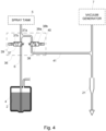
- a system 1 for conveying a sterilizing fluid 2 to a filling machine 3 is shown.
- the filling machine 3 is be configured for forming packages and filling the packages with a liquid food product.
- the sterilizing fluid 2 may be hydrogen peroxide, or any other suitable sterilizing fluid.
- the system 1 includes a refilling tank 4 for containing the sterilizing fluid 2 and a spray tank 5 fluidly connected to the refilling tank via a fluid line 6.
- the system 1 includes a fluid circuit formed of a plurality of fluid lines for transporting fluid through the system 1.
- the fluid may be gas or the sterilizing fluid.
- the fluid circuit may be formed using any suitable pipes, hoses, tubes, or similar fluid transfer devices.
- the fluid lines in the system 1 may be connected using any suitable fluid couplers, fittings, or connectors.
- the sterilizing fluid 2 is drawn from the refilling tank 4 through the fluid line 6 to the spray tank 5.
- the system 1 may be oriented vertically such that the refilling tank 4 is arranged at a bottom of the system 1 and the spray tank 5 is arranged at a location above the refilling tank 4. The sterilizing fluid 2 may thus be drawn upwardly.
- the spray tank 5 is configured for conveying the sterilizing fluid 2 to the filling machine 3.
- the sterilizing fluid 2 may be conveyed to a spray nozzle of the filling machine 3 that is arranged to spray various parts of the filling machine 3. Nozzles of the filling machine 3 may also be arranged to spray packaging material that is handled by the filling machine 3.
- the sterilizing fluid 2 is drawn into the spray tank 5 using a vacuum generator 7 that is fluidly connected to the spray tank 5 via a vacuum line 8.
- the vacuum generator 7 is configured to generate a vacuum in the spray tank 5, such that the vacuum causes the sterilizing fluid 2 to be drawn from the refilling tank 4 as described in further detail below.
- vacuum refers to a pressure that is below the atmospheric pressure in which the system 1 typically operates, capable of drawing liquid from one tank to another.
- the system 1 is operable in a filling mode and a spraying mode that is separate from the filling mode.
- the vacuum generator 7 When the system 1 is in the filling mode, the vacuum generator 7 is in fluid communication with the spray tank 5 for generating the vacuum and drawing the sterilizing fluid 2 into the spray tank 5 to fill the spray tank 5. Fluid communication between the filling machine 3 and the spray tank 5 is closed during the filling mode.
- the system 1 When the system 1 is switched to the spraying mode, the fluid communication between the vacuum generator 7 and the spray tank 5 is closed and the spray tank 5 is pressurized. The pressure in the spray tank 5 forces the sterilizing fluid 2 that was drawn into the spray tank 5 during the filling mode to be discharged from the spray tank 5 and conveyed to the spray nozzle for the filling machine 3.
- Switching the system 1 between the filling mode and the spraying mode may be performed manually, such as by a system operator, or the system 1 may be automated based on the need of sterilization, detected fluid levels and pressure in the system 1.
- the vacuum generator 7 includes a venturi nozzle 9 that is configured to generate a suction or vacuum effect when air is fed through the venturi nozzle 9.
- An air supply valve 10 is fluidly connected to an air supply 11 and the venturi nozzle 9, as shown in Fig. 1 .
- the air supply valve 10 may be a three-way valve.
- the air supply 11 is arranged to supply air to the venturi nozzle 9 through the air supply valve 10 when the air supply valve 10 is open to enable fluid communication between the air supply 11 and the venturi nozzle 9.
- the air supply valve 10 is also connected to a safety valve 12 of the vacuum generator 7 via a vacuum relief line 13 for relieving the vacuum by letting air enter the safety valve 12.
- the safety valve 12 is provided to prevent fluid from reaching the venturi nozzle 9 from the spray tank 5 e.g. in the event that fluid level sensors or pressure sensors in the spray tank 5 undergo a failure and the spray tank becomes over-filled, such that the vacuum causes sterilizing fluid to be drawn into the vacuum line 8.
- the safety valve 12 includes a chamber 12a that is arranged along the vacuum line 8, and a floater 14 located inside the chamber 12a. The floater 14 is configured to rise and close the vacuum line 8 if the sterilizing fluid 2 flows through the vacuum line 8 and enters the chamber 12a.
- a lever 15 is arranged in the chamber 12a and is movable by the floater 14 for closing a vacuum side port 16 of the safety valve 12 in case sterilizing fluid enters the chamber and causes the floater to rise.
- the vacuum side port 16 When the vacuum side port 16 is closed no vacuum is supplied to the vacuum line 8. This prevents sterilizing fluid from reaching the venturi nozzle 9, which has its vacuum port connected to the vacuum side port 16 of the safety valve 12.
- a vacuum relief side port 17 of the safety valve 12 is fluidly connected to the air supply valve 10 via the vacuum relief line 13. The air supply valve 10 can be switched to let in air that reaches the vacuum side port 16. In this way resetting of the safety valve 12 is enabled and any sterilizing fluid can be purged from the safety valve 12 and the vacuum line 8, allowing the fluid to flow back towards the spray tank 5.
- the vacuum side port 16 of the safety valve 12 When the system 1 is in the filling mode, the vacuum side port 16 of the safety valve 12 is open and fluidly connected to the venturi nozzle 9 via a venturi line 18.
- the vacuum When air is fed to the venturi nozzle 9 from the air supply 11, the vacuum is generated in the venturi line 18 and further down in the safety valve 12, the vacuum line 8 and the spray tank 5.
- An air outlet 19 of the venturi nozzle 9 is connected to an air outlet line 20 which is connected between the venturi nozzle 9 and a drain 21 for the system 1. Air that flows through the venturi nozzle 9 to generate the vacuum leaves the system 1 via the drain 21.
- the air supply valve 10 When the system 1 is in the filling mode, the air supply valve 10 is in a first position 10a, in which fluid communication between the air supply 11 and the venturi nozzle 9 is open.
- the air supply valve 10 may be normally biased in a second position 10b and energized by a solenoid 22 to move to the first position 10a.
- air from the air supply 11 When in the first position 10a, air from the air supply 11 is able to flow to the venturi nozzle 9.
- the vacuum relief line 13 is closed by the air supply valve 10 when in the first position 10a.
- the vacuum effect is generated in the venturi nozzle 9 and is effectively generated upstream through the venturi line 18, the open vacuum side port 16 of the safety valve 12, the chamber 12a of the safety valve 12, and the vacuum line 8, to the spray tank 5.
- the vacuum effect thus occurs upwardly through the system 1 toward the venturi nozzle 9.
- the air supply valve 10 When the air supply valve 10 is in the second position it provides communication between the vacuum relief line 13 and the venturi nozzle, and thereby also to the drain 21. Air may then enter form the drain and eventually flow into the chamber 12a of the safety valve. This enables the resetting of the safety valve 12, allowing any fluid therein to flow back towards the spray tank 5.
- the spray tank is located vertically below the safety valve 12.
- pressurized air may be fed into the vacuum relief line 13 for pushing liquid back towards the spray tank 5.
- a pressure control valve 23 is connected between the vacuum line 8 and the spray tank 5 for enabling and preventing fluid communication between the vacuum generator 7 and the spray tank 5.
- the pressure control valve 23 may be a three-way pilot-operated switching valve.
- the pressure control valve 23 is a pressure control valve in the sense that it is used for controlling whether vacuum or pressurized air shall be supplied the spray tank 5, i.e. if under-atmospheric pressure or overatmospheric pressure is provided for the spray tank 5.
- the pressure control valve 23 may be operable by a solenoid 24.
- the pressure control valve 23 When the system 1 is in the filling mode, the pressure control valve 23 is in a first position 23a in which the pressure control valve 23 is open between the vacuum line 8 and the spray tank 5 to enable generation of the vacuum in the spray tank 5.
- the pressure control valve 23 When the system 1 is switched to the spraying mode, the pressure control valve 23 is energized to move from the first position 23a to a second position 23b in which the pressure control valve 23 closes the vacuum line 8 and thus the vacuum generator 7 relative to the spray tank 5.
- the pressure control valve 23 When in the second position 23b, the pressure control valve 23 enables a supply of pressurized air 11' to be in fluid communication with the spray tank 5, such that the spray tank 5 becomes pressurized.
- the air supply is conveyed to the spray tank 5 from an air supply 11' through an air supply valve 25.
- the air supply valve 25 may be a solenoid valve operable by a solenoid 26.
- the air supply valve 25 is normally biased in a first position 25a where the valve 25 is closed, and movable to a second and open position 25b when the solenoid 26 is energized.
- the air supply valve 25 is in the closed position 25a, such that the air supply valve 25 is in the closed position 25a while the pressure control valve 23 is in the first position 23a to enable fluid communication between the vacuum generator 7 and the spray tank 5.
- the pressure control valve 23 When the system 1 is switched to the spraying mode, the pressure control valve 23 is energized to move to the second position 23b and the air supply valve 25 is moved to the open position 25b to open the fluid communication between the supply of pressurized air 11' and the spray tank 5. Then the pressure control valve 23 is in the second position 23b, enabling the supply of pressurized air 11' to pressurize the spray tank 5.
- a filter 27 may be arranged between the air supply valve 25 and the pressure control valve 23 to ensure that only clean air enters the spray tank 5.
- An air-conveying valve 28 is connected between the spray tank 5 and the filling machine 3 for conveying pressurized air to the filling machine 3 during the spraying mode of the system 1.
- the air-conveying valve 28 may be a pilot-operated switching valve.
- the air-conveying valve 28 is operable by a solenoid 29 and normally biased in a closed position 28a in which fluid communication between the spray tank 5 and the filling machine 3 is closed by the air-conveying valve 28.
- the air-conveying valve 28 is in the closed position 28a when the system 1 is in the filling mode.
- the air-conveying valve 28 When the system 1 is switched to the spraying mode, the air-conveying valve 28 is energized to move to an open position 28b in which fluid communication between the spray tank 5 and the filling machine 3 is open such that pressurized air in the spray tank 5 flows out of the spray tank 5 and toward the spraying nozzle of the filling machine 3.
- the pressurized air is mixed with sterilizing fluid at the spray nozzle to generate the spray of sterilizing fluid for spraying.
- a sterilizing fluid control valve 30 is arranged along the fluid line 6 which extends from the refilling tank 4 to the spray tank 5.
- the sterilizing fluid control valve 30 is configured for conveying the sterilizing fluid 2 from the spray tank 5 to the filling machine 3.
- the sterilizing fluid control valve 30 may be a three-way pilot operated switching valve and is supported by a housing 5a that houses the spray tank 5.
- the sterilizing fluid control valve 30 may be operated by a solenoid 31 and normally biased in a first position 30a. When the system 1 is in the filling mode, the sterilizing fluid control valve 30 is in the first position 30a in which the sterilizing fluid control valve 30 enables fluid communication between the fluid line 6 and the spray tank 5 to be open such that the sterilizing fluid 2 may be drawn into the spray tank 5 from the refilling tank 4.
- a filter 32 may also be arranged along the fluid line 6 to ensure that only clean sterilizing fluid enters the spray tank 5.
- the sterilizing fluid control valve 30 When the system 1 is switched to the spraying mode, the sterilizing fluid control valve 30 is energized to move to a second position 30b in which fluid communication between the refilling tank 4 and the spray tank 5 is closed and fluid communication between the spray tank 5 and the filling machine 3 is opened by the sterilizing fluid control valve 30.
- the spray tank 5 When the spray tank 5 is pressurized, the sterilizing fluid 2 that was drawn into the spray tank 5 during the filling mode is pushed out of the spray tank 5 through the sterilizing fluid control valve 30.
- the sterilizing fluid 2 is conveyed to the spray nozzle for the filling machine 3 for mixing with the pressurized air that is supplied via the air-conveying valve 28.
- the air-conveying valve 28 is in the open position 28b such that the air and sterilizing fluid are simultaneously conveyed to the spray nozzle.
- the sterilizing fluid level in the spray tank 5 is regulated such that the outlet to the air-conveying valve 28 from the spray tank 5 remains above the fluid level.
- the outlet to the sterilizing fluid control valve 30 is located at the bottom of the spray tank 5.
- Switching the system 1 between the filling mode and the spraying mode may be performed in response to the fluid level in the spray tank 5.
- Separate fluid level sensors or relays 33, 34 may be mounted in the spray tank 5 for detecting a high level and low level of the sterilizing fluid 2 in the spray tank 5, respectively.
- a pressure transducer 35 is also attached to the spray tank 5 for monitoring the pressure in the spray tank 5. More than one pressure transducer may be provided and the pressure transducers may be arranged at any suitable location along the spray tank 5.
- the air supply valve 25 may be controlled in response to the pressure detected by the pressure transducer 35.
- the air supply valve 25 may be energized to move to the open position 25b if low pressure is detected or to the closed position 25a if high pressure is detected.
- the pressure transducer 35 may also be used to prevent leakages by detecting varying amounts of pressure that occur due to insufficient tightening of fluid connectors or fittings in the fluid circuit.
- the relays 33, 34 include a high level relay 33 for detecting a high level of sterilizing fluid 2 and a low level relay 34 for detecting a low level of sterilizing fluid 2.
- the system 1 may be switched to the filling mode such that the vacuum generator 7 is operated and connected for fluid communication with the spray tank 5.
- the air supply valve 25 is thus moved to the closed position 25a, the air-conveying valve 28 is moved to the first position 28a, the pressure control valve 23 is moved to the first position 23a, and the sterilizing fluid control valve 30 is moved to the first position 30a.
- the air supply valve 10 of the vacuum generator 7 is also moved to the first position 10a.
- the valves may be simultaneously energized to move to the respective positions.
- the system 1 may be switched to the spraying mode in which fluid communication between the vacuum generator 7 and the spray tank 5 is closed such that the sterilizing fluid 2 is no longer drawn into the spray tank 5.
- the air supply valve 25 is moved to the open position 25b
- the pressure control valve 23 is moved to the second position 23b
- the air-conveying valve 28 is moved to the second position 28b
- the sterilizing fluid control valve 30 is moved to the second position 30b.
- the air supply valve 10 of the vacuum generator 7 is moved into the second position 10b for opening the vacuum relief line 13 such that the vacuum from the venturi nozzle 9 is relieved.
- the vacuum relief line 13 is connected to the vacuum relief side port 17 of the safety valve 12 which is open such that opening the vacuum relief line 13 enables atmospheric pressure to be generated in the vacuum line 8 when no air is being fed to the venturi nozzle 9.
- the sterilizing fluid 2 may enter into the vacuum line 8. If the sterilized fluid 2 reaches the chamber 12a of the safety valve 12 arranged along the vacuum line 8, the floater 14 of the safety valve 12 is moved upwardly in the chamber 12a of the safety valve 12a to engage the lever 15 and close the vacuum side port 16 of the safety valve 12. The venturi line 18 to the venturi nozzle 9 is thus also closed. This prevents further filling of sterilizing fluid into the safety valve 12, so that no fluid reaches the venturi nozzle 9. The system 1 may be shut off and restarted after this happens.
- the floater 14 may be pushed downwardly to force the sterilizing fluid 2 back through the vacuum line 8 and into the spray tank 5 by switching the air supply valve 10 to the second position 10b.
- the lever 15 may be a manual valve that is manually operated by the upward and downward movement of the floater 14.
- the sterilizing fluid 2 and air from the venturi nozzle 9 may be drained from the system 1 via the drain 21 during a draining mode.
- the sterilizing fluid 2 may be drained to the same outlet line 20 as the discharged air.
- a separate drain line that is fluidly connected to the drain 21 may also be provided.
- a manifold structure 36 is arranged along the fluid line 6 and includes a loading valve 37 and a drain valve 38.
- the loading valve 37 may be a three-way pilot-operated valve having a solenoid 39.
- the loading valve 37 may be normally biased in a first position 37a in which the loading valve 37 is open and enables fluid communication between the refilling tank 4 and the spray tank 5. During the filling mode of the system 1, the loading valve 37 is open and the drain valve 38 is in a closed position 38a.
- the loading valve 37 is energized to move into a second position 37b in which the loading valve 37 is closed relative to the refilling tank 4 and sterilizing fluid 2 is no longer drawn from the refilling tank 4.
- the loading valve 37 is also in the second position 37b during the spraying mode of the system 1.
- the drain valve 38 is energized to move to an open position 38b.
- the drain valve 38 may be a three-way pilot-operated valve having a solenoid 40 and is normally biased in the closed position 38a.
- a fluid drain line 41 is connected between the fluid line 6 and the drain 21 and the drain valve 38 is arranged along the fluid drain line 41.
- the sterilizing fluid 2 may be emptied from the refilling tank 4 by repeatedly switching between the filling mode and the draining mode.
- the loading valve 37 and the drain valve 38 may be repeatedly opened and closed until all of the sterilizing fluid 2 is discharged to the drain 21.
- the system 1 is initially in the filling mode to draw the sterilizing fluid 2 from the refilling tank 4.
- the air supply valve 25 is in the closed position 25a
- the air-conveying valve 28 is in the first position 28a
- the sterilizing fluid control valve 30 is in the first position 30a
- the pressure control valve 23 is in the first position 23a.
- the spray tank 5 is filled to a predetermined level as detected by the high level relay 34 and the pressure transducer 35
- the system 1 is switched into the draining mode.
- the filling and draining sequence may repeat until all of the sterilizing fluid 2 is removed from the system 1.
- the system 1 may also be configured for an operational mode in which sterilizing fluid is supplied to another unit 42 where sterilization is needed.
- the pressure control valve 23 may be moved to the second position 23b in which the vacuum generator 7 is disconnected from the spray tank 5.
- the vacuum generator 7 and vacuum line 8 may then be fluidly connected to the other unit 42 for generating a vacuum in the unit 42.
- the sterilizing fluid control valve 30 is moved to the second position 30b such that the sterilizing fluid 2 is drawn into the unit 42, rather than to the spray tank 5.
- the sterilizing fluid 2 may be drawn into the unit 42 via an injection fluid line 43 that is fluidly connected to the fluid line 6.
- the filling machine 3 may include the system 1 described herein and a sterilizing unit 44 arranged to receive the sterilizing fluid 2 from the system 1 for sterilizing parts of the filling machine 3.
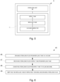
- a method 45 for handling a sterilizing fluid 2 to be used for a filling machine 3 is shown in a flowchart in Fig. 6 .
- the method 45 may be performed using the filling machine 3 of Fig. 5 .
- a step 46 of the method 45 includes drawing the sterilizing fluid 2 from a refilling tank 4.
- Step 46 includes generating a vacuum in the spray tank 5 via a vacuum generator 7 fluidly connected to the spray tank 5.
- a step 47 includes receiving the sterilizing fluid 2 in a spray tank 5 that is fluidly connected to the refilling tank 4.
- a step 48 includes conveying the sterilizing fluid 2 to the filling machine 3.
- a step 49 of the method 44 includes emptying the refilling tank 4 by repeatedly drawing the sterilizing fluid 2 into the spray tank 5 and draining the sterilizing fluid 2 out of the spray tank 5 until the refilling tank 4 is empty.
- the system and method for conveying a sterilizing fluid to a filling machine is advantageous in that the system efficiently draws a sufficient amount of sterilizing fluid from the refilling tank to supply the fluid downstream and spray the filling machine.
- Another advantage of the system is that pressure sensors and separate fluid level sensors are used to detect real-time characteristics of the spray tank such that the system may accommodate for overpressure and leakage.
- the vacuum generator advantageously includes a safety valve for the venturi nozzle that prevents a feed of air to the venturi nozzle during a failure of the fluid level sensors or the pressure sensors for the spray tank.
- the refilling tank may be easily emptied by a repeated process of drawing the sterilizing fluid into the spray tank and discharging the sterilizing fluid to the drain.
Landscapes
- Health & Medical Sciences (AREA)
- Mechanical Engineering (AREA)
- Engineering & Computer Science (AREA)
- General Health & Medical Sciences (AREA)
- Epidemiology (AREA)
- Life Sciences & Earth Sciences (AREA)
- Animal Behavior & Ethology (AREA)
- Public Health (AREA)
- Veterinary Medicine (AREA)
- Chemical & Material Sciences (AREA)
- General Chemical & Material Sciences (AREA)
- Chemical Kinetics & Catalysis (AREA)
- Dispersion Chemistry (AREA)
- Apparatus For Disinfection Or Sterilisation (AREA)
- Filling Of Jars Or Cans And Processes For Cleaning And Sealing Jars (AREA)
Claims (15)
- Füllmaschine (3), die dazu angeordnet ist, flüssiges Nahrungsmittelprodukt in Verpackungen zu füllen, wobei die Füllmaschine (3) ein System (1) zum Leiten eines Sterilisationsfluids (2) zu der Füllmaschine (3) umfasst, dadurch gekennzeichnet, dass das System (1) Folgendes umfasst:einen Nachfülltank (4), der dazu ausgelegt ist, das Sterilisationsfluid (2) zu enthalten, und aus dem das Sterilisationsfluid (2) gesaugt wird,einen Sprühtank (5), der mit dem Nachfülltank (4) strömungstechnisch verbunden ist, um das Sterilisationsfluid (2) aus dem Nachfülltank (4) aufzunehmen und das Sterilisationsfluid (2) zu der Füllmaschine (3) zu leiten, wobei die Füllmaschine (3) eine Sprühdüse umfasst, die dazu ausgelegt ist, verschiedene Teile der Füllmaschine (3) zu besprühen, wobei der Sprühtank (5) dazu ausgelegt ist, das Sterilisationsfluid zu der Sprühdüse zu leiten,eine Fluidleitung (6), die den Nachfülltank (4) mit dem Sprühtank (5) verbindet, undeinen Unterdruckerzeuger (7), der mit dem Sprühtank (5) über eine Unterdruckleitung (8) strömungstechnisch verbunden und dazu ausgelegt ist, einen Unterdruck in dem Sprühtank (5) zu erzeugen, so dass der Unterdruck bewirkt, dass das Sterilisationsfluid (2) aus dem Nachfülltank (4) und in den Sprühtank (5) gesaugt wird.
- Füllmaschine (3) nach Anspruch 1, wobei der Unterdruckerzeuger (7) eine Venturidüse (9) umfasst, die dazu ausgelegt ist, den Unterdruck zu erzeugen, wenn Luft durch die Venturidüse (9) gespeist wird.
- Füllmaschine (3) nach Anspruch 2, wobei der Unterdruckerzeuger (7) ein Sicherheitsventil (12) umfasst, das dazu ausgelegt ist, ein Speisen von Luft durch die Venturidüse (9) zu stoppen, wenn das Sterilisationsfluid (2) in die Unterdruckleitung (8) eintritt.
- Füllmaschine (3) nach Anspruch 3, wobei das Sicherheitsventil (12) eine Kammer (12a), die entlang der Unterdruckleitung (8) angeordnet ist, und einen Schwimmer (14), der sich in der Kammer (12a) befindet und dazu ausgelegt ist, zu steigen und die Unterdruckleitung (8) zu schließen, wenn das Sterilisationsfluid (2) in die Kammer (12a) eintritt, umfasst.
- Füllmaschine (3) nach Anspruch 3 oder 4, wobei der Unterdruckerzeuger (7) Folgendes umfasst:ein Luftzufuhrventil (10), das mit der Venturidüse (9) zum Speisen von Luft zu der Venturidüse (9) verbunden ist, undeine Unterdruckabbauleitung (13), die zwischen dem Luftzufuhrventil (10) und dem Sicherheitsventil (12) verbunden ist, um den Unterdruck in dem Unterdruckerzeuger (7) abzubauen und ein Rücksetzen des Sicherheitsventils (12) zu ermöglichen, falls es ausgelöst hat.
- Füllmaschine (3) nach Anspruch 5, wobei das Luftzufuhrventil (10) dazu ausgelegt ist, sich zwischen Folgendem zu bewegen- einer ersten Position (10a), die ermöglicht, dass die Luft zu der Venturidüse (9) gespeist wird, während die Unterdruckabbauleitung (13) geschlossen wird, und- einer zweiten Position (10b), die verhindert, dass Luft zu der Venturidüse (9) gespeist wird, während die Unterdruckabbauleitung (13) geöffnet wird, wodurch atmosphärischer Druck in der Unterdruckabbauleitung (13) ermöglicht wird.
- Füllmaschine (3) nach einem der vorhergehenden Ansprüche, umfassend:einen Ablauf (21), der dazu ausgelegt ist, Sterilisationsfluid aus dem System (1) abzulassen,ein Ladeventil (37), das zwischen dem Nachfülltank (4) und dem Sprühtank (5) verbunden ist, um zu ermöglichen, dass das Sterilisationsfluid (2) in den Sprühtank (5) gesaugt wird, wenn das Ladeventil (37) geöffnet ist, undeine Fluidablaufleitung (41), die zwischen dem Nachfülltank (4) und dem Ablauf (21) verbunden ist, um das Sterilisationsfluid (2) aus dem Sprühtank (5) abzulassen, wenn das Ladeventil (37) geschlossen ist.
- Füllmaschine (3) nach Anspruch 7, umfassend ein Ablaufventil (38), das entlang der Fluidablaufleitung (41) angeordnet ist, um den Nachfülltank (4) zu leeren, wenn das Ablaufventil (38) geöffnet ist und das Ladeventil (37) geschlossen ist, und wobei die Venturidüse (9) einen Luftauslass (19) aufweist, der mit dem Ablauf (21) über eine Luftauslassleitung (20) verbunden ist, um Luft aus der Venturidüse (9) abzulassen.
- Füllmaschine (3) nach einem der vorhergehenden Ansprüche, wobei die Füllmaschine (3) dazu ausgelegt ist, Verpackungen auszubilden und die Verpackungen mit dem flüssigen Nahrungsmittelprodukt zu füllen.
- Füllmaschine (3) nach einem der vorhergehenden Ansprüche, wobei der Sprühtank (5) einen Druckwandler (35) umfasst, der dazu ausgelegt ist, einen Druck in dem Sprühtank (5) zu überwachen.
- Füllmaschine (3) nach einem der vorhergehenden Ansprüche, wobei der Sprühtank (5) ein Hochpegelrelais (33) und ein Niederpegelrelais (34) umfasst, die jeweils dazu ausgelegt sind, einen Pegel des Sterilisationsfluids (2) in dem Sprühtank (5) zu detektieren.
- Füllmaschine (3) nach einem der vorhergehenden Ansprüche, umfassend:ein Drucksteuerventil (23) für den Sprühtank (5), das dazu ausgelegt ist, sich zwischen Folgendem zu bewegen- einer ersten Position (23a), die eine Verbindung zwischen dem Sprühtank (5) und dem Unterdruckerzeuger (7) bereitstellt, um zu ermöglichen, dass der Unterdruck in dem Sprühtank (5) erzeugt wird, und- einer zweiten Position (23b), die eine Verbindung zwischen dem Sprühtank (5) und einem Luftzufuhrventil (25) bereitstellt, um zu ermöglichen, dass Druckluft in den Sprühtank (5) eintritt, um zum Leiten eines Sterilisationsfluids (2) verwendet zu werden, undein Sterilisationsfluidsteuerventil (30), das dazu ausgelegt ist, sich zwischen Folgendem zu bewegen- einer ersten Position (30a), die eine Verbindung zwischen dem Sprühtank (5) und dem Nachfülltank (4) bereitstellt, um zu ermöglichen, dass das Sterilisationsfluid (2) aus dem Nachfülltank (4) und in den Sprühtank (5) gesaugt wird, und- einer zweiten Position (30b), die eine Verbindung zwischen dem Sprühtank (5) und der Füllmaschine (3) bereitstellt, um zu ermöglichen, dass das Sterilisationsfluid (2) zu der Füllmaschine (3) geleitet wird.
- Füllmaschine (3) nach einem der vorhergehenden Ansprüche, wobei das System (1) in einem Füllmodus und in einem Sprühmodus, der von dem Füllmodus separat ist, betreibbar ist, wobei:
in einem Füllmodus der Unterdruckerzeuger (7) in strömungstechnischer Verbindung mit dem Sprühtank (5) ist, um den Unterdruck zu erzeugen und das Sterilisationsfluid (2) in den Sprühtank (5) zu saugen, um den Sprühtank (5) zu füllen, und eine strömungstechnische Verbindung zwischen der Füllmaschine (3) und dem Sprühtank (5) geschlossen ist;
in dem Sprühmodus die strömungstechnische Verbindung zwischen dem Unterdruckerzeuger (7) und dem Sprühtank (5) geschlossen ist und der Sprühtank (5) druckbeaufschlagt ist, so dass Druck in dem Sprühtank (5) das Sterilisationsfluid (2), das während des Füllmodus in den Sprühtank (5) gesaugt wurde, zwingt, aus dem Sprühtank (5) ausgelassen und zu der Sprühdüse für die Füllmaschine (3) geleitet zu werden. - Verfahren (45) zum Handhaben eines Sterilisationsfluids (2), das für eine Füllmaschine (3) verwendet werden soll, die dazu angeordnet ist, flüssiges Nahrungsmittelprodukt in Verpackungen zu füllen, wobei das Verfahren (45) Folgendes umfasst:Saugen (46) des Sterilisationsfluids (2) aus einem Nachfülltank (4),Aufnehmen (47) des Sterilisationsfluids (2) in einem Sprühtank (5), der strömungstechnisch mit dem Nachfülltank (4) verbunden ist, undLeiten (48) des Sterilisationsfluids (2) zu der Füllmaschine (3),wobei das Sterilisationsfluid (2) zu einer Sprühdüse der Füllmaschine (3) geleitet wird, die dazu angeordnet ist, verschiedene Teil der Füllmaschine (3) zu besprühen,wobei das Saugen (46) Erzeugen eines Unterdrucks in dem Sprühtank (5) über einen Unterdruckerzeuger (7), der strömungstechnisch mit dem Sprühtank (5) verbunden ist, umfasst.
- Verfahren (45) nach Anspruch 14, wobei das Sterilisationsfluid (2) Wasserstoffperoxid ist.
Applications Claiming Priority (1)
| Application Number | Priority Date | Filing Date | Title |
|---|---|---|---|
| EP20165919 | 2020-03-26 |
Publications (2)
| Publication Number | Publication Date |
|---|---|
| EP3885277A1 EP3885277A1 (de) | 2021-09-29 |
| EP3885277B1 true EP3885277B1 (de) | 2023-03-01 |
Family
ID=70049887
Family Applications (1)
| Application Number | Title | Priority Date | Filing Date |
|---|---|---|---|
| EP21164275.6A Active EP3885277B1 (de) | 2020-03-26 | 2021-03-23 | System zur förderung von sterilisierflüssigkeit |
Country Status (5)
| Country | Link |
|---|---|
| US (1) | US20230158192A1 (de) |
| EP (1) | EP3885277B1 (de) |
| JP (1) | JP2023518574A (de) |
| CN (1) | CN114929581B (de) |
| WO (1) | WO2021191200A1 (de) |
Families Citing this family (1)
| Publication number | Priority date | Publication date | Assignee | Title |
|---|---|---|---|---|
| CN116765060A (zh) * | 2023-08-11 | 2023-09-19 | 詹家绮 | 真空包装机的管路清洗系统 |
Family Cites Families (16)
| Publication number | Priority date | Publication date | Assignee | Title |
|---|---|---|---|---|
| US2059455A (en) * | 1935-01-21 | 1936-11-03 | Natural Food Products Company | Automatic air release means for vacuum systems |
| US2784748A (en) * | 1954-11-19 | 1957-03-12 | Eichenlaub Richard | Vacuum filling apparatus |
| CA2024304C (en) * | 1989-09-15 | 1996-12-10 | Norwin Ced Derby | Vacuum fill system |
| JPH0725375B2 (ja) * | 1989-12-11 | 1995-03-22 | 凸版印刷株式会社 | 無菌充填包装機 |
| JP2808492B2 (ja) * | 1991-01-28 | 1998-10-08 | 三菱重工業株式会社 | 充填機の洗浄殺菌装置 |
| JP3324274B2 (ja) * | 1994-05-23 | 2002-09-17 | 石川島播磨重工業株式会社 | 流量計 |
| US6425408B1 (en) * | 1995-08-02 | 2002-07-30 | Marcus J. Engle | Vacuum transfer system utilizing biased ball |
| US5832948A (en) * | 1996-12-20 | 1998-11-10 | Chemand Corp. | Liquid transfer system |
| US6702985B1 (en) * | 1999-07-15 | 2004-03-09 | Steuben Foods, Inc. | Apparatus and method for providing container interior sterilization in an aseptic processing apparatus |
| JP2001341796A (ja) * | 2000-06-02 | 2001-12-11 | Mitsubishi Heavy Ind Ltd | 液体充填機の残水排出装置 |
| JP2006176133A (ja) * | 2004-12-20 | 2006-07-06 | Iwai Kikai Kogyo Co Ltd | 液体殺菌充填方法及びその装置 |
| JP4542949B2 (ja) * | 2005-06-03 | 2010-09-15 | 東製株式会社 | 充填機 |
| DE102006007481B3 (de) * | 2006-02-17 | 2007-07-12 | Khs Ag | Anlage zum kaltaseptischen Abfüllen eines flüssigen Füllgutes in Flaschen oder dergleichen Behälter |
| JP5843115B2 (ja) * | 2012-04-19 | 2016-01-13 | 株式会社エナ | 四酸化二窒素による滅菌法及び滅菌装置 |
| CN105229353B (zh) * | 2013-03-22 | 2019-01-22 | 百事可乐公司 | 容器填充系统和用于容器填充系统的阀 |
| EP3160244B1 (de) * | 2014-06-30 | 2018-03-07 | Tetra Laval Holdings & Finance SA | Verfahren zur effizienten entleerung eines systems mit einem flüssigprodukt |
-
2021
- 2021-03-23 EP EP21164275.6A patent/EP3885277B1/de active Active
- 2021-03-23 US US17/913,591 patent/US20230158192A1/en not_active Abandoned
- 2021-03-23 CN CN202180008068.2A patent/CN114929581B/zh active Active
- 2021-03-23 WO PCT/EP2021/057413 patent/WO2021191200A1/en not_active Ceased
- 2021-03-23 JP JP2022557917A patent/JP2023518574A/ja active Pending
Also Published As
| Publication number | Publication date |
|---|---|
| JP2023518574A (ja) | 2023-05-02 |
| EP3885277A1 (de) | 2021-09-29 |
| US20230158192A1 (en) | 2023-05-25 |
| CN114929581A (zh) | 2022-08-19 |
| WO2021191200A1 (en) | 2021-09-30 |
| CN114929581B (zh) | 2025-09-26 |
Similar Documents
| Publication | Publication Date | Title |
|---|---|---|
| EP2076159B1 (de) | Emulgationsvorrichtung zur herstellung schäumender milch und ähnlicher getränke sowie entsprechendes verfahren | |
| WO1995020127A1 (en) | Chemical refill system for high purity chemicals | |
| EP3116357A1 (de) | Verfahren zum reinigen und/oder desinfizieren eines milchführenden systems einer kaffeemaschine sowie kaffeemaschine | |
| EP3885277A1 (de) | System zur förderung von sterilisierflüssigkeit | |
| CN112897440B (zh) | 具有cip清洁装置的用于填充容器的设备 | |
| CN107260112A (zh) | 内窥镜清洗消毒装置、内窥镜的清洗方法 | |
| CA2472616A1 (en) | Non tank pressurizing fast fill receiver and system for vehicles | |
| US7575015B2 (en) | Secondarily contained in-dispenser sump/pan system and method for capturing and monitoring leaks | |
| KR102455451B1 (ko) | 고압 처리를 위한 플러그, 기계, 및 방법 | |
| US6142169A (en) | Sterile tank venting system for a filling machine | |
| CN106793937B (zh) | 内窥镜清洗消毒机和故障探测方法 | |
| KR100613307B1 (ko) | 유체 혼합 장치 | |
| CN217568137U (zh) | 一种汽水用二氧化碳回收循环装置 | |
| CN110864222B (zh) | 汽车总装车间集中供液系统 | |
| CN117881621A (zh) | 用于处理keg桶容器的处理头 | |
| JP7185085B1 (ja) | 無菌脱圧送液装置及び充填システム | |
| KR101159656B1 (ko) | 원료 공급장치 및 공급 방법 | |
| CN110834772B (zh) | 一种灌装用防溢出装置及方法 | |
| JP2021104826A (ja) | 送液システムおよび送液方法 | |
| JP2006225147A (ja) | 食品等の間歇供給装置及び食品等の間歇供給方法 | |
| JP6075676B1 (ja) | 送液システム | |
| JP3201263B2 (ja) | 薬液移送装置 | |
| CN213463616U (zh) | 压力装置及农药制剂设备 | |
| AU713925B2 (en) | A filling device for a refillable distributing container and process for filling the distributing container | |
| SU1730029A1 (ru) | Устройство дл автоматизированного розлива сметаны во фл ги |
Legal Events
| Date | Code | Title | Description |
|---|---|---|---|
| PUAI | Public reference made under article 153(3) epc to a published international application that has entered the european phase |
Free format text: ORIGINAL CODE: 0009012 |
|
| STAA | Information on the status of an ep patent application or granted ep patent |
Free format text: STATUS: THE APPLICATION HAS BEEN PUBLISHED |
|
| AK | Designated contracting states |
Kind code of ref document: A1 Designated state(s): AL AT BE BG CH CY CZ DE DK EE ES FI FR GB GR HR HU IE IS IT LI LT LU LV MC MK MT NL NO PL PT RO RS SE SI SK SM TR |
|
| STAA | Information on the status of an ep patent application or granted ep patent |
Free format text: STATUS: REQUEST FOR EXAMINATION WAS MADE |
|
| 17P | Request for examination filed |
Effective date: 20220329 |
|
| RBV | Designated contracting states (corrected) |
Designated state(s): AL AT BE BG CH CY CZ DE DK EE ES FI FR GB GR HR HU IE IS IT LI LT LU LV MC MK MT NL NO PL PT RO RS SE SI SK SM TR |
|
| GRAP | Despatch of communication of intention to grant a patent |
Free format text: ORIGINAL CODE: EPIDOSNIGR1 |
|
| STAA | Information on the status of an ep patent application or granted ep patent |
Free format text: STATUS: GRANT OF PATENT IS INTENDED |
|
| INTG | Intention to grant announced |
Effective date: 20221014 |
|
| GRAS | Grant fee paid |
Free format text: ORIGINAL CODE: EPIDOSNIGR3 |
|
| GRAA | (expected) grant |
Free format text: ORIGINAL CODE: 0009210 |
|
| STAA | Information on the status of an ep patent application or granted ep patent |
Free format text: STATUS: THE PATENT HAS BEEN GRANTED |
|
| AK | Designated contracting states |
Kind code of ref document: B1 Designated state(s): AL AT BE BG CH CY CZ DE DK EE ES FI FR GB GR HR HU IE IS IT LI LT LU LV MC MK MT NL NO PL PT RO RS SE SI SK SM TR |
|
| REG | Reference to a national code |
Ref country code: GB Ref legal event code: FG4D |
|
| REG | Reference to a national code |
Ref country code: CH Ref legal event code: EP Ref country code: AT Ref legal event code: REF Ref document number: 1550813 Country of ref document: AT Kind code of ref document: T Effective date: 20230315 |
|
| REG | Reference to a national code |
Ref country code: DE Ref legal event code: R096 Ref document number: 602021001492 Country of ref document: DE |
|
| REG | Reference to a national code |
Ref country code: IE Ref legal event code: FG4D |
|
| P01 | Opt-out of the competence of the unified patent court (upc) registered |
Effective date: 20230426 |
|
| REG | Reference to a national code |
Ref country code: LT Ref legal event code: MG9D |
|
| REG | Reference to a national code |
Ref country code: NL Ref legal event code: MP Effective date: 20230301 |
|
| PG25 | Lapsed in a contracting state [announced via postgrant information from national office to epo] |
Ref country code: RS Free format text: LAPSE BECAUSE OF FAILURE TO SUBMIT A TRANSLATION OF THE DESCRIPTION OR TO PAY THE FEE WITHIN THE PRESCRIBED TIME-LIMIT Effective date: 20230301 Ref country code: NO Free format text: LAPSE BECAUSE OF FAILURE TO SUBMIT A TRANSLATION OF THE DESCRIPTION OR TO PAY THE FEE WITHIN THE PRESCRIBED TIME-LIMIT Effective date: 20230601 Ref country code: LV Free format text: LAPSE BECAUSE OF FAILURE TO SUBMIT A TRANSLATION OF THE DESCRIPTION OR TO PAY THE FEE WITHIN THE PRESCRIBED TIME-LIMIT Effective date: 20230301 Ref country code: LT Free format text: LAPSE BECAUSE OF FAILURE TO SUBMIT A TRANSLATION OF THE DESCRIPTION OR TO PAY THE FEE WITHIN THE PRESCRIBED TIME-LIMIT Effective date: 20230301 Ref country code: HR Free format text: LAPSE BECAUSE OF FAILURE TO SUBMIT A TRANSLATION OF THE DESCRIPTION OR TO PAY THE FEE WITHIN THE PRESCRIBED TIME-LIMIT Effective date: 20230301 Ref country code: ES Free format text: LAPSE BECAUSE OF FAILURE TO SUBMIT A TRANSLATION OF THE DESCRIPTION OR TO PAY THE FEE WITHIN THE PRESCRIBED TIME-LIMIT Effective date: 20230301 |
|
| REG | Reference to a national code |
Ref country code: AT Ref legal event code: MK05 Ref document number: 1550813 Country of ref document: AT Kind code of ref document: T Effective date: 20230301 |
|
| PG25 | Lapsed in a contracting state [announced via postgrant information from national office to epo] |
Ref country code: SE Free format text: LAPSE BECAUSE OF FAILURE TO SUBMIT A TRANSLATION OF THE DESCRIPTION OR TO PAY THE FEE WITHIN THE PRESCRIBED TIME-LIMIT Effective date: 20230301 Ref country code: PL Free format text: LAPSE BECAUSE OF FAILURE TO SUBMIT A TRANSLATION OF THE DESCRIPTION OR TO PAY THE FEE WITHIN THE PRESCRIBED TIME-LIMIT Effective date: 20230301 Ref country code: NL Free format text: LAPSE BECAUSE OF FAILURE TO SUBMIT A TRANSLATION OF THE DESCRIPTION OR TO PAY THE FEE WITHIN THE PRESCRIBED TIME-LIMIT Effective date: 20230301 Ref country code: GR Free format text: LAPSE BECAUSE OF FAILURE TO SUBMIT A TRANSLATION OF THE DESCRIPTION OR TO PAY THE FEE WITHIN THE PRESCRIBED TIME-LIMIT Effective date: 20230602 Ref country code: FI Free format text: LAPSE BECAUSE OF FAILURE TO SUBMIT A TRANSLATION OF THE DESCRIPTION OR TO PAY THE FEE WITHIN THE PRESCRIBED TIME-LIMIT Effective date: 20230301 |
|
| PG25 | Lapsed in a contracting state [announced via postgrant information from national office to epo] |
Ref country code: SM Free format text: LAPSE BECAUSE OF FAILURE TO SUBMIT A TRANSLATION OF THE DESCRIPTION OR TO PAY THE FEE WITHIN THE PRESCRIBED TIME-LIMIT Effective date: 20230301 Ref country code: RO Free format text: LAPSE BECAUSE OF FAILURE TO SUBMIT A TRANSLATION OF THE DESCRIPTION OR TO PAY THE FEE WITHIN THE PRESCRIBED TIME-LIMIT Effective date: 20230301 Ref country code: PT Free format text: LAPSE BECAUSE OF FAILURE TO SUBMIT A TRANSLATION OF THE DESCRIPTION OR TO PAY THE FEE WITHIN THE PRESCRIBED TIME-LIMIT Effective date: 20230703 Ref country code: EE Free format text: LAPSE BECAUSE OF FAILURE TO SUBMIT A TRANSLATION OF THE DESCRIPTION OR TO PAY THE FEE WITHIN THE PRESCRIBED TIME-LIMIT Effective date: 20230301 Ref country code: CZ Free format text: LAPSE BECAUSE OF FAILURE TO SUBMIT A TRANSLATION OF THE DESCRIPTION OR TO PAY THE FEE WITHIN THE PRESCRIBED TIME-LIMIT Effective date: 20230301 Ref country code: AT Free format text: LAPSE BECAUSE OF FAILURE TO SUBMIT A TRANSLATION OF THE DESCRIPTION OR TO PAY THE FEE WITHIN THE PRESCRIBED TIME-LIMIT Effective date: 20230301 |
|
| PG25 | Lapsed in a contracting state [announced via postgrant information from national office to epo] |
Ref country code: SK Free format text: LAPSE BECAUSE OF FAILURE TO SUBMIT A TRANSLATION OF THE DESCRIPTION OR TO PAY THE FEE WITHIN THE PRESCRIBED TIME-LIMIT Effective date: 20230301 Ref country code: IS Free format text: LAPSE BECAUSE OF FAILURE TO SUBMIT A TRANSLATION OF THE DESCRIPTION OR TO PAY THE FEE WITHIN THE PRESCRIBED TIME-LIMIT Effective date: 20230701 |
|
| REG | Reference to a national code |
Ref country code: BE Ref legal event code: MM Effective date: 20230331 |
|
| REG | Reference to a national code |
Ref country code: DE Ref legal event code: R097 Ref document number: 602021001492 Country of ref document: DE |
|
| PG25 | Lapsed in a contracting state [announced via postgrant information from national office to epo] |
Ref country code: LU Free format text: LAPSE BECAUSE OF NON-PAYMENT OF DUE FEES Effective date: 20230323 |
|
| PLBE | No opposition filed within time limit |
Free format text: ORIGINAL CODE: 0009261 |
|
| STAA | Information on the status of an ep patent application or granted ep patent |
Free format text: STATUS: NO OPPOSITION FILED WITHIN TIME LIMIT |
|
| PG25 | Lapsed in a contracting state [announced via postgrant information from national office to epo] |
Ref country code: MC Free format text: LAPSE BECAUSE OF FAILURE TO SUBMIT A TRANSLATION OF THE DESCRIPTION OR TO PAY THE FEE WITHIN THE PRESCRIBED TIME-LIMIT Effective date: 20230301 |
|
| REG | Reference to a national code |
Ref country code: IE Ref legal event code: MM4A |
|
| PG25 | Lapsed in a contracting state [announced via postgrant information from national office to epo] |
Ref country code: SI Free format text: LAPSE BECAUSE OF FAILURE TO SUBMIT A TRANSLATION OF THE DESCRIPTION OR TO PAY THE FEE WITHIN THE PRESCRIBED TIME-LIMIT Effective date: 20230301 Ref country code: MC Free format text: LAPSE BECAUSE OF FAILURE TO SUBMIT A TRANSLATION OF THE DESCRIPTION OR TO PAY THE FEE WITHIN THE PRESCRIBED TIME-LIMIT Effective date: 20230301 Ref country code: IE Free format text: LAPSE BECAUSE OF NON-PAYMENT OF DUE FEES Effective date: 20230323 Ref country code: DK Free format text: LAPSE BECAUSE OF FAILURE TO SUBMIT A TRANSLATION OF THE DESCRIPTION OR TO PAY THE FEE WITHIN THE PRESCRIBED TIME-LIMIT Effective date: 20230301 Ref country code: FR Free format text: LAPSE BECAUSE OF NON-PAYMENT OF DUE FEES Effective date: 20230501 |
|
| 26N | No opposition filed |
Effective date: 20231204 |
|
| PG25 | Lapsed in a contracting state [announced via postgrant information from national office to epo] |
Ref country code: BE Free format text: LAPSE BECAUSE OF NON-PAYMENT OF DUE FEES Effective date: 20230331 |
|
| REG | Reference to a national code |
Ref country code: CH Ref legal event code: PL |
|
| PG25 | Lapsed in a contracting state [announced via postgrant information from national office to epo] |
Ref country code: BG Free format text: LAPSE BECAUSE OF FAILURE TO SUBMIT A TRANSLATION OF THE DESCRIPTION OR TO PAY THE FEE WITHIN THE PRESCRIBED TIME-LIMIT Effective date: 20230301 |
|
| PG25 | Lapsed in a contracting state [announced via postgrant information from national office to epo] |
Ref country code: BG Free format text: LAPSE BECAUSE OF FAILURE TO SUBMIT A TRANSLATION OF THE DESCRIPTION OR TO PAY THE FEE WITHIN THE PRESCRIBED TIME-LIMIT Effective date: 20230301 |
|
| PG25 | Lapsed in a contracting state [announced via postgrant information from national office to epo] |
Ref country code: CH Free format text: LAPSE BECAUSE OF NON-PAYMENT OF DUE FEES Effective date: 20240331 |
|
| PG25 | Lapsed in a contracting state [announced via postgrant information from national office to epo] |
Ref country code: CY Free format text: LAPSE BECAUSE OF FAILURE TO SUBMIT A TRANSLATION OF THE DESCRIPTION OR TO PAY THE FEE WITHIN THE PRESCRIBED TIME-LIMIT; INVALID AB INITIO Effective date: 20210323 |
|
| PG25 | Lapsed in a contracting state [announced via postgrant information from national office to epo] |
Ref country code: HU Free format text: LAPSE BECAUSE OF FAILURE TO SUBMIT A TRANSLATION OF THE DESCRIPTION OR TO PAY THE FEE WITHIN THE PRESCRIBED TIME-LIMIT; INVALID AB INITIO Effective date: 20210323 |
|
| GBPC | Gb: european patent ceased through non-payment of renewal fee |
Effective date: 20250323 |
|
| PG25 | Lapsed in a contracting state [announced via postgrant information from national office to epo] |
Ref country code: TR Free format text: LAPSE BECAUSE OF FAILURE TO SUBMIT A TRANSLATION OF THE DESCRIPTION OR TO PAY THE FEE WITHIN THE PRESCRIBED TIME-LIMIT Effective date: 20230301 |
|
| PG25 | Lapsed in a contracting state [announced via postgrant information from national office to epo] |
Ref country code: GB Free format text: LAPSE BECAUSE OF NON-PAYMENT OF DUE FEES Effective date: 20250323 |
|
| PGFP | Annual fee paid to national office [announced via postgrant information from national office to epo] |
Ref country code: DE Payment date: 20260320 Year of fee payment: 6 |
|
| PGFP | Annual fee paid to national office [announced via postgrant information from national office to epo] |
Ref country code: IT Payment date: 20260320 Year of fee payment: 6 |