EP3885659B1 - Vorrichtung und verfahren zur kühlung eines raumes - Google Patents
Vorrichtung und verfahren zur kühlung eines raumes Download PDFInfo
- Publication number
- EP3885659B1 EP3885659B1 EP21164815.9A EP21164815A EP3885659B1 EP 3885659 B1 EP3885659 B1 EP 3885659B1 EP 21164815 A EP21164815 A EP 21164815A EP 3885659 B1 EP3885659 B1 EP 3885659B1
- Authority
- EP
- European Patent Office
- Prior art keywords
- room
- air flow
- evaporation
- supply air
- liquid
- Prior art date
- Legal status (The legal status is an assumption and is not a legal conclusion. Google has not performed a legal analysis and makes no representation as to the accuracy of the status listed.)
- Active
Links
Images
Classifications
-
- F—MECHANICAL ENGINEERING; LIGHTING; HEATING; WEAPONS; BLASTING
- F24—HEATING; RANGES; VENTILATING
- F24F—AIR-CONDITIONING; AIR-HUMIDIFICATION; VENTILATION; USE OF AIR CURRENTS FOR SCREENING
- F24F5/00—Air-conditioning systems or apparatus not covered by F24F1/00 or F24F3/00, e.g. using solar heat or combined with household units such as an oven or water heater
- F24F5/0007—Air-conditioning systems or apparatus not covered by F24F1/00 or F24F3/00, e.g. using solar heat or combined with household units such as an oven or water heater cooling apparatus specially adapted for use in air-conditioning
- F24F5/0035—Air-conditioning systems or apparatus not covered by F24F1/00 or F24F3/00, e.g. using solar heat or combined with household units such as an oven or water heater cooling apparatus specially adapted for use in air-conditioning using evaporation
-
- F—MECHANICAL ENGINEERING; LIGHTING; HEATING; WEAPONS; BLASTING
- F24—HEATING; RANGES; VENTILATING
- F24F—AIR-CONDITIONING; AIR-HUMIDIFICATION; VENTILATION; USE OF AIR CURRENTS FOR SCREENING
- F24F3/00—Air-conditioning systems in which conditioned primary air is supplied from one or more central stations to distributing units in the rooms or spaces where it may receive secondary treatment; Apparatus specially designed for such systems
- F24F3/12—Air-conditioning systems in which conditioned primary air is supplied from one or more central stations to distributing units in the rooms or spaces where it may receive secondary treatment; Apparatus specially designed for such systems characterised by the treatment of the air otherwise than by heating and cooling
- F24F3/14—Air-conditioning systems in which conditioned primary air is supplied from one or more central stations to distributing units in the rooms or spaces where it may receive secondary treatment; Apparatus specially designed for such systems characterised by the treatment of the air otherwise than by heating and cooling by humidification; by dehumidification
- F24F3/1411—Air-conditioning systems in which conditioned primary air is supplied from one or more central stations to distributing units in the rooms or spaces where it may receive secondary treatment; Apparatus specially designed for such systems characterised by the treatment of the air otherwise than by heating and cooling by humidification; by dehumidification by absorbing or adsorbing water, e.g. using an hygroscopic desiccant
-
- F—MECHANICAL ENGINEERING; LIGHTING; HEATING; WEAPONS; BLASTING
- F24—HEATING; RANGES; VENTILATING
- F24F—AIR-CONDITIONING; AIR-HUMIDIFICATION; VENTILATION; USE OF AIR CURRENTS FOR SCREENING
- F24F3/00—Air-conditioning systems in which conditioned primary air is supplied from one or more central stations to distributing units in the rooms or spaces where it may receive secondary treatment; Apparatus specially designed for such systems
- F24F3/12—Air-conditioning systems in which conditioned primary air is supplied from one or more central stations to distributing units in the rooms or spaces where it may receive secondary treatment; Apparatus specially designed for such systems characterised by the treatment of the air otherwise than by heating and cooling
- F24F3/14—Air-conditioning systems in which conditioned primary air is supplied from one or more central stations to distributing units in the rooms or spaces where it may receive secondary treatment; Apparatus specially designed for such systems characterised by the treatment of the air otherwise than by heating and cooling by humidification; by dehumidification
- F24F2003/144—Air-conditioning systems in which conditioned primary air is supplied from one or more central stations to distributing units in the rooms or spaces where it may receive secondary treatment; Apparatus specially designed for such systems characterised by the treatment of the air otherwise than by heating and cooling by humidification; by dehumidification by dehumidification only
-
- F—MECHANICAL ENGINEERING; LIGHTING; HEATING; WEAPONS; BLASTING
- F24—HEATING; RANGES; VENTILATING
- F24F—AIR-CONDITIONING; AIR-HUMIDIFICATION; VENTILATION; USE OF AIR CURRENTS FOR SCREENING
- F24F3/00—Air-conditioning systems in which conditioned primary air is supplied from one or more central stations to distributing units in the rooms or spaces where it may receive secondary treatment; Apparatus specially designed for such systems
- F24F3/12—Air-conditioning systems in which conditioned primary air is supplied from one or more central stations to distributing units in the rooms or spaces where it may receive secondary treatment; Apparatus specially designed for such systems characterised by the treatment of the air otherwise than by heating and cooling
- F24F3/14—Air-conditioning systems in which conditioned primary air is supplied from one or more central stations to distributing units in the rooms or spaces where it may receive secondary treatment; Apparatus specially designed for such systems characterised by the treatment of the air otherwise than by heating and cooling by humidification; by dehumidification
- F24F2003/144—Air-conditioning systems in which conditioned primary air is supplied from one or more central stations to distributing units in the rooms or spaces where it may receive secondary treatment; Apparatus specially designed for such systems characterised by the treatment of the air otherwise than by heating and cooling by humidification; by dehumidification by dehumidification only
- F24F2003/1446—Air-conditioning systems in which conditioned primary air is supplied from one or more central stations to distributing units in the rooms or spaces where it may receive secondary treatment; Apparatus specially designed for such systems characterised by the treatment of the air otherwise than by heating and cooling by humidification; by dehumidification by dehumidification only by condensing
-
- Y—GENERAL TAGGING OF NEW TECHNOLOGICAL DEVELOPMENTS; GENERAL TAGGING OF CROSS-SECTIONAL TECHNOLOGIES SPANNING OVER SEVERAL SECTIONS OF THE IPC; TECHNICAL SUBJECTS COVERED BY FORMER USPC CROSS-REFERENCE ART COLLECTIONS [XRACs] AND DIGESTS
- Y02—TECHNOLOGIES OR APPLICATIONS FOR MITIGATION OR ADAPTATION AGAINST CLIMATE CHANGE
- Y02B—CLIMATE CHANGE MITIGATION TECHNOLOGIES RELATED TO BUILDINGS, e.g. HOUSING, HOUSE APPLIANCES OR RELATED END-USER APPLICATIONS
- Y02B30/00—Energy efficient heating, ventilation or air conditioning [HVAC]
- Y02B30/54—Free-cooling systems
Definitions
- the invention relates to a device for cooling a room, comprising at least one evaporation device configured to evaporate a liquid and release it into the room. Furthermore, the invention relates to a method for cooling a room, comprising at least one evaporation device, with which a liquid is evaporated and released into the room.
- high humidity has the disadvantage that the hygienic conditions in the room deteriorate, for example, through the formation of mold on surfaces, mite growth in upholstered furniture and carpets and/or the development of musty odors.
- US 2003/033821 A1 discloses a device for cooling a room and a method for cooling a room according to the preamble of claims 1 and 8. Further devices for cooling a room are known from DE 10 2009 009582 A1 , US 2018/163982 A1 , US 4 171 620 A and US 5 890 372 A known.
- the invention is therefore based on the object of specifying a device and a method for cooling a room which operate in an energy-efficient manner and avoid adverse effects on the room climate.
- the room can be at least one room of a building and can be used, for example, as a living space, storage space, meeting room, office space, or assembly hall.
- the building can be separated from the environment by external walls that limit the exchange of air and heat between the room and the environment.
- the room can be part of a railway carriage or other vehicle or a ship and can be similarly separated from the environment by external walls.
- the invention it is proposed to arrange at least one evaporation device within the room, which is configured to evaporate a liquid and release it into the room.
- the liquid preferably contains, but not necessarily, water.
- the liquid consists predominantly or entirely of water.
- the evaporation device is configured to convert the water from the liquid to the gaseous state. The latent heat required for this is at least partially extracted from the room air, which is thereby cooled.
- the device according to the invention contains at least one ventilation device to which a fresh air stream can be supplied and which is configured to discharge this fresh air stream into the room as a supply air stream.
- the ventilation device contains at least one conveying device, for example a radial, axial, or roller fan with an electrically driven fan wheel.
- the ventilation device can, in some cases, contain heat recovery devices so that heat losses or heat gains through ventilation are reduced.
- the ventilation device can contain other components, such as air ducts or ducts or filters.
- the ventilation device further comprises a drying device which is designed to extract moisture from the fresh air flow and to release this dehumidified fresh air flow into the room as supply air flow.
- the device According to the invention, it is now proposed that during operation of the device, the supply air flow and the liquid only come into contact with each other inside the room. Unlike ventilation systems that humidify directly in the supply air duct, the device according to the invention thus avoids contamination of the supply air ducts with mold spores or biofilms. Even if the ventilation system is designed as a central ventilation system for an entire building, only dry air flows are guided through the supply air ducts of this ventilation system, which have no negative impact on the cleanliness of the supply air ducts. Unlike with known ventilation systems, the air is therefore not conditioned outside the room in the ventilation system and then this conditioned air is introduced into the room.
- the device according to the invention is particularly suitable for modernizing old buildings, as complex installation work can be eliminated.
- the evaporation capacity of the evaporation device can be increased, resulting in greater cooling capacity, which enables a lower room temperature or higher heat load in the room.
- the supply air flow is further processed before being fed into the room.
- the processing of the supply air flow can be selected from filtering and/or heating and/or Cooling or other treatment.
- more than one ventilation system may be present, or a ventilation system may perform several of the aforementioned functions simultaneously, sequentially, or alternatively.
- the drying device can lower the relative humidity of the supply air flow by about 2% to about 30% or by about 5% to about 20% than the relative humidity of the fresh air flow.
- the drying device can control or regulate the relative humidity of the supply air flow such that the relative humidity in the room remains constant, i.e., the relative humidity of the supply air flow must be lower than the relative humidity in the room.
- a constant relative humidity in the room means a humidity that fluctuates over time by no more than ⁇ 10%, no more than ⁇ 5%, no more than ⁇ 2%, or no more than ⁇ 1%.
- the drying device can be selected from a condensation dryer and/or an adsorption dryer.
- Adsorption dryers have the advantage of higher drying capacity, allowing either a greater air exchange rate in the room or more effective dehumidification of the air, thus further increasing the evaporation capacity of the evaporation device and thus heat dissipation.
- Condensation dryers have the advantage that they can be operated with lower primary energy consumption. Furthermore, the water separated from the fresh air stream can be removed from the room via a collection tank or a wastewater line, without necessarily requiring the installation of a complex exhaust air line.
- the ventilation device can be configured to extract the fresh air flow from room air and/or outside air. Accordingly, either the room air is dehumidified and then fed back into the room as dry supply air.
- the fresh air flow can be fed into the room from outside the building. In dry climates in temperate latitudes or the subtropics, this can also eliminate the need for additional dehumidification by a drying device.
- heat recovery of the room air discharged from the room can be advantageous in order to pre-cool the outside air and minimize energy losses. Furthermore, such heat or enthalpy recovery can lead to a decrease in the relative humidity of the supply air flow compared to the fresh air flow.
- the evaporation device can have an evaporation surface onto which the liquid can be applied or is applied during operation of the evaporation device. Since evaporation removes heat from the room air, such an embodiment of the evaporation device leads to additional cooling of the evaporation surface. This allows the human body or another heat source in the room to transfer additional radiant heat to the evaporation surface, thus further dissipating heat.
- the evaporation device may have an evaporation surface selected from a porous material and/or a glass and/or a ceramic and/or a natural stone and/or a living plant material.
- the plant material may be selected from one or more mosses or common houseplants or green plants.
- Each embodiment of the evaporation surface has specific advantages, so that the person skilled in the art can Depending on the specific application, a suitable evaporation surface or several different evaporation surfaces can be selected.
- a porous material such as pumice stone, metal foam, expanded clay, or a similar, open-pored material, has a larger surface area, which can increase evaporation performance and thus cooling performance. Smooth surfaces such as glass or ceramic and some natural stones can be particularly easy to maintain, so that contamination of the room air by mold spores or biofilms can be reduced or even completely prevented.
- mosses or other plants combines high evaporation performance through large surfaces, an appealing aesthetic design, and self-cleaning through the constant renewal of the plant material as the plant grows. Plants can also grow on porous evaporation surfaces, thus combining the advantages of large surfaces with those of plant material.
- the evaporation surface can be horizontal and, for example, be part of an indoor fountain or a pond. In other embodiments of the invention, the evaporation surface can be inclined so that the liquid to be evaporated flows over the evaporation surface by gravity. This ensures a constant exchange, which can improve the hygienic conditions at the evaporation device.
- the supply air flow can be guided over the evaporation surface of the evaporation device. This allows the evaporation process accelerated, thus increasing the cooling capacity.
- the supply air flow is guided through the evaporation surface of the evaporation device, thus maintaining intensive contact with the liquid or a liquid film.
- the device contains at least one humidity sensor, with which the supply air flow provided by the ventilation system can be controlled or regulated.
- the humidity in the room can be maintained within a desired range without adverse effects on the room or the users.
- Such problems that impair user acceptance can arise, on the one hand, from the dry supply air flow being too strong and the humidity in the room being reduced too drastically.
- problems can also arise from the supply air flow being too low and the humidity increasing too sharply due to the cooling.
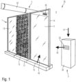
- Figure 1 shows a room 5, which is bounded by interior and/or exterior walls (not shown).
- the room may, for example, be part of an office building or a residential building, a meeting place, a sports facility, or another building. Accordingly, room 5 is intended for use by people or animals or as a storage room.
- the device 55 according to the invention serves this purpose.
- the device 55 contains at least one evaporation device 1 and at least one ventilation device 2 or 3.
- the illustrated embodiment two ventilation devices are present.
- the invention only teaches the presence of at least one ventilation device 2 or 3, with a further ventilation device being optional.
- the evaporation device 1 has three evaporation surfaces 11, 12 and 13.
- the evaporation surfaces 11 and 13 are made of glass or plastic in a transparent or translucent
- the evaporation surface 12 contains a plant substrate covered with mosses or leafy plants.
- All evaporation surfaces are positioned approximately vertically on the floor of room 5.
- the liquid to be evaporated is thus applied to the top of the evaporation surfaces and runs down the evaporation surfaces 11, 12, and 13 to a collection container located in the base 17 of the evaporation device 1. From there, the liquid can either be drained away via a drain or reapplied to the evaporation surfaces by means of a circulation pump.
- the liquid can either be introduced into a porous plant substrate of the evaporation surface and from there released into room 5 via the leaf surfaces of the plants. Alternatively or additionally, the liquid can also be applied directly to the leaf surfaces of the plants and evaporated from there.
- the invention does not teach the use of exactly three evaporation surfaces 11, 12, and 13 as a solution principle.
- the number of evaporation surfaces in space 5 may be greater or lesser, for example, between 1 and about 50 or between about 2 and about 10, wherein a single evaporation surface may have a surface area of about 1 m 2 to about 10 m 2 or from about 1 m 2 to about 5 m 2 .
- the evaporation device 1 is designed as a partition wall, which can be freely positioned in the room 5.
- the partition wall can thus be used, for example, as a room divider or as an acoustic panel.
- the evaporation surfaces 11, 12 and 13 can be held in an optional frame 14, which in turn is connected to the base 17 of the evaporation surface and the evaporation device 1 in the desired position.
- the evaporation surfaces 11, 12, and 13 can be wetted on both sides with the liquid to be evaporated.
- the evaporation of the liquid on the evaporation surfaces 11, 12, and 13 directly extracts heat energy from the room, thus lowering the air temperature. Furthermore, the evaporation surface itself cools down, allowing it to serve as a heat sink for infrared radiation emitted by people or technical devices in room 5. This allows the average of the air and radiation temperatures to decrease further, thus improving the effectiveness of the device according to the invention.
- device 55 further includes at least one ventilation device 2 or 3.
- Ventilation device 2 is configured as a central ventilation device that can direct a supply air flow 42 into several or all rooms of a building.
- ventilation device 2 includes a central device that includes at least one conveying device, at least one central fresh air supply, and at least one drying device, as well as other optional elements, such as filter systems, heating registers, and/or heat recovery devices.
- the ventilation device 2 can extract fresh air either from the outside of the building or from at least one room 5, dry it and, if necessary, heat it and/or filter it, and introduce it into the room 5 via at least one supply air duct 22 and at least one air outlet 25.
- the supply of dry air and the optional removal of moist air from the room 5 results in the humidity, which increases due to the operation of the evaporation device 1, falling back to a comfortable level. Since the supply air duct 22 itself does not contain humidified air, but rather untreated or at most By transporting dried supply air, the formation of mold or other harmful biofilms inside the supply air duct 22 is reduced or impossible.
- the dry air from the ventilation system 2 only encounters the moisture from the evaporation system 1 inside the room 5, so that no part of the entire ventilation system comes into contact with an unacceptably high level of humidity.
- At least one decentralized ventilation system 3 can also be provided.
- the decentralized ventilation system 3 can, for example, contain a condensation or adsorption dryer.
- the ventilation system 3 can, alternatively or additionally, also contain a heat recovery system, a heating register, and/or a conveying system, for example a fan. All components of the ventilation system 3 are combined in at least one housing 32, which in some embodiments of the invention can be freely positioned in the room 5.
- the components of the ventilation system 3 can also be distributed in several components, which can be arranged at different locations inside or outside the room.
- a refrigeration system can advantageously be arranged outside the building in a manner known per se and connected to the other components of the ventilation system 3 by lines.
- the decentralized ventilation system 3 is designed to draw in a fresh air flow 41. This can, for example, be taken directly from room 5. Alternatively or additionally, the fresh air flow 41 can also be supplied from the outside through the building envelope.
- the fresh air stream 41 is dried in the ventilation device 3 and optionally filtered and/or heated and then supplied to the room 5 via the air outlet 35 as the supply air stream 42.
- This drier supply air stream 42 with a lower relative humidity than the fresh air stream 41, thus in turn leads to a reduction in the relative humidity in the room 5, so that the humidity increasing due to the operation of the evaporation device 1 can be compensated.
- the evaporation device 1 itself can have an outflow element 15, which directs a dry supply air flow 42 directly onto or into the evaporation surface 11, 12, or 13. This can increase the evaporation performance, so that a greater temperature difference between the interior of the room 5 and the exterior can be achieved or, at the same temperature in the room 5, a greater heat load can be introduced.
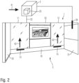
- FIG. 2 shows a second embodiment of the invention. Identical components of the invention are provided with the same reference numerals, so the following description is limited to the essential differences.
- Figure 2 shows a room 5. Furthermore, three boundary surfaces or walls 51, 52, and 53 are shown.
- the outer wall 51 is constructed, for example, as a lightweight or solid wall, for example, from concrete, masonry, or a timber frame construction.
- the interior walls 52 and 53 can also be constructed as solid or lightweight walls.
- the evaporation device 1 is not positioned freely in the room as a partition wall, but is integrated into the inner wall 52.
- the inner wall 52 Partial surfaces are formed as evaporation surfaces 11 and 12.
- the liquid to be evaporated for example water with or without additives, is applied to these evaporation surfaces in the ceiling area so that it runs as a thin film over the evaporation surfaces and is collected by a drainage channel in the lower area.
- a base 18 Located in the floor area is a base 18, which can accommodate drainage channels, pipes, and/or optional circulation pumps for the liquid. Furthermore, the base 18 contains supply air ducts 22, which lead into outlet elements 15. From there, a supply air stream 42, centrally provided by the ventilation system 2, is directed to the evaporation surfaces 11 and 12. This reduces the humidity in room 5 to enable a comfortable indoor climate. Furthermore, the evaporation performance is increased by supplying a dried supply air stream 42 to provide improved cooling performance.
- the supply air flow 42 is provided by a ventilation device 2, which sucks in a fresh air flow 41 and dehumidifies it in an optional drying device 23 to such an extent that the relative humidity of the supply air flow 42 is approximately 2% to approximately 30% or approximately 5% to approximately 20% lower than the relative humidity of the fresh air flow 41.
- the supply air preconditioned in this way is guided via the supply air line 22 to the outflow elements 15.
- an optional humidity sensor 26 can measure the relative humidity in room 5 and transmit this value to the ventilation device 2.
- the amount of the supply air flow 42 and/or the relative humidity of the supply air flow 42 can thus be regulated or controlled in the ventilation device 2 in order to keep the humidity in room 5 within a predeterminable range.
Landscapes
- Engineering & Computer Science (AREA)
- Chemical & Material Sciences (AREA)
- Combustion & Propulsion (AREA)
- Mechanical Engineering (AREA)
- General Engineering & Computer Science (AREA)
- Life Sciences & Earth Sciences (AREA)
- Sustainable Development (AREA)
- Central Air Conditioning (AREA)
- Building Environments (AREA)
Description
- Die Erfindung betrifft eine Vorrichtung zur Kühlung eines Raumes mit zumindest einer Verdunstungseinrichtung, welche dazu eingerichtet ist, eine Flüssigkeit zu verdunsten und diese in den Raum abzugeben. Weiterhin betrifft die Erfindung ein Verfahren zur Kühlung eines Raumes mit zumindest einer Verdunstungseinrichtung, mit welcher eine Flüssigkeit verdunstet und in den Raum abgegeben wird.
- Aus der Praxis ist bekannt, dass die Verdunstung von Wasser einen spürbaren Kühleffekt besitzt. Wird Wasser an einer Oberfläche in einem Raum eines Gebäudes verdunstet, so wird die zur Verdunstung erforderliche latente Wärme der Raumluft entzogen, welche sich dadurch abkühlt. Darüber hinaus kühlt sich die zur Verdunstung verwendete Oberfläche ab, sodass im Raum befindliche Personen oder Abwärme erzeugende Geräte Strahlungswärme an die Oberfläche abgeben können. Der Mittelwert aus Luft- und Strahlungstemperatur sinkt dadurch ab, sodass sich die Komfortbedingungen im Sommer bzw. in heißen Klimaten verbessern können.
- Dieses Vorgehen weist den Nachteil auf, dass durch die Kühlung die Luftfeuchte im Raum ansteigt. Dies führt dazu, dass die thermische Behaglichkeit wieder sinkt, da sich das Dampfdruckgefälle zwischen Hautoberfläche und Raumluft verringert. Hierdurch kann die Thermoregulation des Menschen nachteilig beeinflusst werden.
- Darüber hinaus hat eine hohe Luftfeuchte den Nachteil, dass sich die hygienischen Verhältnisse im Raum verschlechtern, beispielsweise durch Schimmelbildung an Oberflächen, Milbenwachstum in Polstermöbeln und Teppichen und/oder Entstehung von Modergerüchen.
- Weiterhin ist aus dem Stand der Technik bekannt, durch Kompressionskältemaschinen, welche außerhalb des Gebäudes angeordnet sind, einem Wärmeträgermedium Wärme zu entziehen. Das solchermaßen abgekühlte Wärmeträgermedium kann einem im Raum befindlichen Wärmetauscher zugeführt werden und dort der Raumluft Wärme entziehen. Solche Klimatisierungsanlagen weisen jedoch einen hohen Energieverbrauch auf.
-
US 2003/033821 A1 offenbart eine Vorrichtung zur Kühlung eines Raumes und ein Verfahren zur Kühlung eines Raumes nach der Präambel der Ansprüche 1 und 8. Weitere Vorrichtungen zur Kühlung eines Raumes sind ausDE 10 2009 009582 A1 ,US 2018/163982 A1 ,US 4 171 620 A undUS 5 890 372 A bekannt. - Ausgehend vom Stand der Technik liegt der Erfindung somit die Aufgabe zugrunde, eine Vorrichtung und ein Verfahren zur Kühlung eines Raumes anzugeben, welche energieeffizient arbeiten und nachteilige Auswirkungen auf das Raumklima vermeiden.
- Die Aufgabe wird erfindungsgemäß durch eine Vorrichtung gemäß Anspruch 1 und ein Verfahren nach Anspruch 8 gelöst. Vorteilhafte Weiterbildungen der Erfindung finden sich in den Unteransprüchen.
- Erfindungsgemäß wird eine Vorrichtung zur Kühlung eines Raumes vorgeschlagen. Der Raum kann zumindest ein Raum eines Gebäudes sein und beispielsweise als Wohnraum, Lagerraum, Besprechungsraum oder Büroraum oder Versammlungsstätte Verwendung finden. Das Gebäude kann durch Außenwände von der Umgebung getrennt sein, welche den Luft- und Wärmeaustausch zwischen dem Raum und der Umgebung begrenzen. In anderen Ausführungsformen der Erfindung kann der Raum Teil eines Eisenbahnwagens oder eines anderen Fahrzeuges oder eines Schiffes sein und in gleicher Weise durch Außenwände von der Umgebung getrennt sein.
- Erfindungsgemäß wird vorgeschlagen, innerhalb des Raumes zumindest eine Verdunstungseinrichtung anzuordnen, welche dazu eingerichtet ist, eine Flüssigkeit zu verdunsten und diese in den Raum abzugeben. Die Flüssigkeit enthält bevorzugt, aber nicht zwingend, Wasser. In einigen Ausführungsformen der Erfindung besteht die Flüssigkeit überwiegend oder vollständig aus Wasser. Die Verdunstungseinrichtung ist dazu eingerichtet, das Wasser vom flüssigen in den gasförmigen Zustand zu überführen. Die hierzu erforderliche latente Wärme wird zumindest teilweise der Raumluft entnommen, welche sich dadurch abkühlt.
- Weiterhin enthält die erfindungsgemäße Vorrichtung zumindest eine Lüftungseinrichtung, welcher ein Frischluftstrom zuführbar ist und welche dazu eingerichtet ist, diesen Frischluftstrom als Zuluftstrom in den Raum abzugeben. Hierzu enthält die Lüftungseinrichtung zumindest eine Fördereinrichtung, beispielsweise einen Radial- oder Axial- oder Walzenlüfter mit einem elektrisch angetriebenen Lüfterrad. Die Lüftungseinrichtung kann fallweise Einrichtungen zur Wärmerückgewinnung enthalten, sodass Wärmeverluste bzw. Wärmegewinne durch die Lüftung reduziert sind. Darüber hinaus kann die Lüftungseinrichtung weitere Bauteile enthalten, wie beispielsweise Luftführungsrohre oder -kanäle oder Filter.
- Die Lüftungseinrichtung kann eine zentrale Lüftungseinrichtung sein, welche alle oder zumindest eine Mehrzahl von Räumen des Gebäudes mit Frischluft versorgt. In anderen Ausführungsformen der Erfindung kann die Lüftungseinrichtung eine raumselektive Lüftung sein, beispielsweise ein in der Außenwand des Gebäudes angeordneter Pendellüfter, welcher abwechselnd verbrauchte Raumluft entnimmt und in den Außenbereich abführt und Frischluft aus dem Außenraum des Gebäudes ansaugt und als Zuluftstrom dem Raum zuführt. In einigen Ausführungsformen der Erfindung kann die Lüftungseinrichtung eine Umluftlüftung sein, welche einen Frischluftstrom aus der Raumluft entnimmt, diesen aufbereitet und und als Zuluft dem Raum wieder zuführt.
- Erfindungsgemäß enthält die Lüftungseinrichtung weiterhin eine Trocknungseinrichtung, welche dazu eingerichtet ist, dem Frischluftstrom Feuchte zu entziehen und diesen entfeuchteten Frischluftstrom als Zuluftstrom in den Raum abzugeben.
- Erfindungsgemäß wird nun vorgeschlagen, dass bei Betrieb der Vorrichtung der Zuluftstrom und die Flüssigkeit erst innerhalb des Raumes miteinander in Kontakt kommen. Anders als bei lufttechnischen Anlagen, welche eine Befeuchtung unmittelbar in der Zuluftleitung vornehmen, vermeidet die erfindungsgemäße Vorrichtung somit die Kontamination der Zuluftleitungen mit Schimmelsporen bzw. Biofilmen. Selbst wenn die Lüftungseinrichtung als zentrale Lüftungseinrichtung für ein gesamtes Gebäude ausgeführt ist, so werden in den Zuluftleitungen dieser Lüftungseinrichtung ausschließlich trockene Luftströme geführt, welche keine negativen Auswirkungen auf die Sauberkeit der Zuluftleitungen haben. Anders als bei bekannten lufttechnischen Anlagen wird somit die Luftkonditionierung nicht außerhalb des Raumes in der lufttechnischen Anlage vorgenommen und sodann diese konditionierte Luft in den Raum eingeleitet. Erfindungsgemäß wird hingegen vorgeschlagen, trockene Zuluft und verdunstete Flüssigkeit zur Kühlung und Befeuchtung erst innerhalb des Raumes zusammenzubringen. Neben der verbesserten Hygiene eignet sich die erfindungsgemäße Vorrichtung insbesondere auch zur Altbaumodernisierung, da aufwändige Installationsarbeiten entfallen können. Durch die Trockung des Zuluftstroms kann die Verdunstungsleistung der Verdunstungseinrichtung erhöht sein, sodass sich eine größere Kühlleistung ergibt, welche eine niedrigere Raumtemperatur bzw. höhere Wärmelast im Raum ermöglicht.
- In einigen Ausführungsformen der Erfindung wird der Zuluftstrom noch weiter aufbereitet, ehe er dem Raum zugeführt wird. Die Aufbereitung des Zuluftstroms kann ausgewählt seinaus einer Filterung und/oder einer Erwärmung und/oder Kühlung oder einer anderweitigen Behandlung. Fallweise kann mehr als eine Lüftungseinrichtung vorhanden sein oder aber eine Lüftungseinrichtung, welche mehrere der genannten Funktionen gleichzeitig oder sequenziell oder alternativ ausführt.
- In einigen Ausführungsformen der Erfindung kann durch die Trocknungseinrichtung die relative Feuchte des Zuluftstromes um etwa 2 % bis etwa 30 % oder um etwa 5 % bis etwa 20 % niedriger sein als die relative Feuchte des Frischluftstromes. In einigen Ausführungsformen der Erfindung kann durch die Trocknungseinrichtung die relative Feuchte des Zuluftstromes so gesteuert oder geregelt werden, dass die relative Feuchte im Raum konstant bleibt, d.h. die relative Feuchte des Zuluftstromes muss niedriger sein als die relative Feuchte im Raum. In einigen Ausführungsformen der Erfindung bedeutet eine konstante relative Feuchte im Raum eine Feuchte, welche zeitlich um nicht mehr als ± 10% oder nicht mehr als ± 5% oder nicht mehr als ± 2% oder nicht mehr als ± 1% schwankt.
- In einigen Ausführungsformen der Erfindung kann die Trocknungseinrichtung ausgewählt sein aus einem Kondensationstrockner und/oder einem Adsorptionstrockner. Adsorptionstrockner weisen dabei den Vorteil einer höheren Trocknungsleistung auf, sodass entweder ein größerer Luftwechsel im Raum ermöglicht wird oder die Luft stärker entfeuchtet werden kann, sodass die Verdunstungsleistung der Verdunstungseinrichtung und damit die Wärmeabfuhr weiter ansteigen kann. Kondensationstrockner weisen den Vorteil auf, dass diese mit geringerem Primärenergieeinsatz betrieben werden können. Darüber hinaus kann das aus dem Frischluftstrom abgeschiedene Wasser über einen Sammeltank oder eine Abwasserleitung aus dem Raum entfernt werden, ohne dass in jedem Fall eine aufwendige Abluftleitung installiert werden muss.
- In einigen Ausführungsformen der Erfindung kann die Lüftungseinrichtung dazu eingerichtet sein, den Frischluftstrom einer Raumluft und/oder einer Außenluft zu entnehmen. Dementsprechend wird entweder die Raumluft entfeuchtet und dem Raum als trockene Zuluft wieder zugeführt. In anderen Ausführungsformen der Erfindung kann der Frischluftstrom von außerhalb des Gebäudes dem Raum zugeführt werden. In trockenen Klimaten der gemäßigten Breiten oder der Subtropen kann hierdurch eine zusätzliche Entfeuchtung durch eine Trocknungseinrichtung auch entfallen. Fallweise kann eine Wärmerückgewinnung der aus dem Raum abgeführten Raumluft vorteilhaft sein, um die Außenluft vorzukühlen und Energieverluste zu minimieren. Darüber hinaus kann eine solche Wärme- oder Enthalpierückgewinnung dazu führen, dass die relative Feuchte des Zuluftstromes gegenüber dem Frischluftstrom abnimmt.
- In einigen Ausführungsformen der Erfindung kann die Verdunstungseinrichtung eine Verdunstungsfläche aufweisen, auf welcher die Flüssigkeit aufbringbar ist bzw. bei Betrieb der Verdunstungseinrichtung aufgebracht wird. Da die Verdunstung der Raumluft Wärme entzieht, führt eine solche Ausführungsform der Verdunstungseinrichtung dazu, dass die Verdunstungsfläche zusätzlich abkühlt. Hierdurch kann der menschliche Körper oder eine andere Wärmequelle im Raum zusätzlich Strahlungswärme an die Verdunstungsfläche abgeben und so zusätzlich entwärmt werden.
- In einigen Ausführungsformen der Erfindung kann die Verdunstungseinrichtung eine Verdunstungsfläche aufweisen, welche ausgewählt ist aus einem porösen Material und/oder einem Glas und/oder einer Keramik und/oder einem Naturstein und/oder einem lebenden pflanzlichen Material. Das pflanzliche Material kann ausgewählt sein aus einem oder mehreren Moosen oder gängigen Zimmerpflanzen bzw. Grünpflanzen. Jede Ausführungsform der Verdunstungsfläche weist spezifische Vorteile auf, sodass der Fachmann in Abhängigkeit des konkreten Anwendungsfalles eine geeignete Verdunstungsfläche oder auch mehrere verschiedene Verdunstungsflächen auswählen kann. So weist ein poröses Material, beispielsweise ein Bimsstein, ein Metallschaum, ein Blähton, oder ein ähnliches, offenporiges Material eine größere Oberfläche auf, welche die Verdunstungsleistung und damit die Kühlleistung steigern kann. Glattflächige Oberflächen wie beispielsweise Glas oder Keramik und manche Natursteine können besonders pflegeleicht sein, sodass die Kontamination der Raumluft durch Schimmelsporen oder Biofilme reduziert sein oder sogar ganz verhindert werden kann.
- Die Verwendung von Naturstein, Glas oder Keramik eröffnet darüber hinaus besondere Gestaltungsmöglichkeiten, welche eine gefällige Integration der erfindungsgemäßen Vorrichtung in verschiedene Räume ermöglicht. Die Verwendung von Moosen oder anderen Pflanzen vereint eine hohe Verdunstungsleistung durch große Oberflächen, eine ansprechende ästhetische Gestaltung und eine Selbstreinigung durch ständige Erneuerung des Pflanzenmaterials bei Wachstum der betreffenden Pflanze. Pflanzen können insbesondere auch auf porösen Verdunstungsflächen wachsen und so die Vorteile großer Oberflächen mit den Vorteilen des pflanzlichen Materials vereinen.
- Die Verdunstungsfläche kann in einigen Ausführungsformen waagrecht sein und beispielsweise Teil eines Zimmerbrunnens oder eines Teiches sein. In anderen Ausführungsformen der Erfindung kann die Verdunstungsfläche geneigt sein, sodass die zu verdunstende Flüssigkeit schwerkraftgetrieben über die Verdunstungsfläche läuft. Hierdurch wird ein ständiger Austausch sichergestellt, welcher die hygienischen Verhältnisse an der Verdunstungseinrichtung verbessern kann.
- In einigen Ausführungsformen der Erfindung kann der Zuluftstrom über die Verdunstungsfläche der Verdunstungseinrichtung geführt werden. Hierdurch kann der Verdunstungsprozess beschleunigt werden, sodass sich die Kühlleistung erhöht. Demselben Zweck dienen Ausführungsformen, bei welchen der Zuluftstrom durch die Verdunstungsfläche der Verdunstungseinrichtung hindurchgeführt wird und somit intensiven Kontakt zur Flüssigkeit bzw. einem Flüssigkeitsfilm erhält.
- In einigen Ausführungsformen der Erfindung enthält die Vorrichtung zumindest einen Feuchtesensor, mit welchem der durch die Lüftungseinrichtung bereitgestellte Zuluftstrom steuer- oder regelbar ist. Somit kann die Luftfeuchte im Raum im einen gewünschten Bereich gehalten werden, ohne dass nachteilige Auswirkungen auf den Raum bzw. die Benutzer auftreten. Solche, die Nutzerakzeptanz beeinträchtigenden Probleme können einerseits dadurch entstehen, dass der trockene Zuluftstrom zu stark ist und die Luftfeuchtigkeit im Raum zu stark reduziert wird. Andererseits können Probleme jedoch auch dadurch entstehen, dass der Zuluftstrom zu gering ist und die Luftfeuchtigkeit durch die Kühlung zu stark ansteigt.
- In einigen Ausführungsformen der Erfindung enthält die Verdunstungseinrichtung keine Kühleinrichtung für die zu verdunstende Flüssigkeit. Die zu verdunstende Flüssigkeit kann somit eine Temperatur aufweisen, welche von der Raumtemperatur um etwa -10 K bis etwa +10 K oder um etwa -5 K bis etwa +5 K oder um etwa -10 K bis etwa +1 K oder um etwa -8 K bis etwa 0 K oder um etwa -2 K bis etwa +2 K abweicht. Sofern die zu verdampfende Flüssigkeit Wasser ist bzw. Wasser enthält, kann dieses somit beispielsweise unmittelbar einem öffentlichen Leitungsnetz entnommen oder in einem Kreislauf zirkuliert werden, ohne dass eine weitere Aufbereitung bzw. Kühlung erforderlich ist. Das wärmere Wasser kann einerseits eine höhere Verdunstungsrate aufweisen. Andererseits wird zusätzlicher Energieeinsatz für die Kühlung der in den Raum eingebrachten Flüssigkeit vermieden. Nachfolgend soll die Erfindung anhand von Ausführungsbeispielen und Figuren näher erläutert werden. Dabei zeigt:
- .Figur 1
- ein erstes Ausführungsbeispiel einer erfindungsgemäßen Vorrichtung zur Kühlung eines Raumes.
- Figur 2
- zeigt ein zweites Ausführungsbeispiel einer erfindungsgemäßen Vorrichtung zur Kühlung eines Raumes.
-
Figur 1 zeigt einen Raum 5, welcher durch nicht dargestellte Innen- und/oder Außenwände begrenzt wird. Der Raum kann beispielsweise Teil eines Bürogebäudes oder eines Wohngebäudes, einer Versammlungsstätte, einer Sportanlage oder eines anderen Gebäudes sein. Der Raum 5 ist dementsprechend zur Benutzung durch Menschen oder Tiere oder als Lagerraum vorgesehen. - Bei heißer Witterung, beispielsweise im mitteleuropäischen Sommer oder, in anderen Klimaten, auch ganzjährig, steigt die Temperatur im Raum 5 an, so dass das Wohlbefinden der sich im Raum aufhaltenden Personen beeinträchtigt werden kann. Es besteht somit eine Notwendigkeit, den Raum 5 zu kühlen. Hierzu dient die erfindungsgemäße Vorrichtung 55.
- Wie aus
Figur 1 ersichtlich ist, enthält die Vorrichtung 55 zumindest eine Verdunstungseinrichtung 1 und zumindest eine Lüftungseinrichtung 2 oder 3. Im dargestellten Ausführungsbeispiel sind zwei Lüftungseinrichtungen vorhanden. Die Erfindung lehrt jedoch lediglich das Vorhandensein zumindest einer Lüftungseinrichtung 2 oder 3, wobei eine weitere Lüftungseinrichtung optional ist. - Die Verdunstungseinrichtung 1 weist im dargestellten Ausführungsbeispiel drei Verdunstungsflächen 11, 12 und 13 auf. Die Verdunstungsflächen 11 und 13 sind dabei aus einem Glas oder Kunststoff in transparenter oder transluzenter Ausführung gefertigt. Demgegenüber enthält die Verdunstungsfläche 12 ein Pflanzsubstrat, welches durch Moose oder Blattpflanzen begrünt ist.
- Sämtliche Verdunstungsflächen stehen in etwa senkrecht auf dem Boden des Raumes 5. Die zu verdunstende Flüssigkeit wird somit oben auf die Verdunstungsflächen aufgebracht und läuft an den Verdunstungsflächen 11, 12 und 13 herab, bis zu einem Sammelbehälter, welcher im Sockel 17 der Verdunstungseinrichtung 1 angeordnet ist. Von dort kann die Flüssigkeit entweder über einen Ablauf abgeführt oder mittels einer Umwälzpumpe erneut auf die Verdunstungsflächen aufgebracht werden. Im Falle der begrünten Verdunstungsfläche 12 kann die Flüssigkeit entweder in ein poröses Pflanzsubstrat der Verdunstungsfläche eingebracht und von dort über die Blattoberflächen der Pflanzen an den Raum 5 abgegeben werden. Alternativ oder zusätzlich kann die Flüssigkeit auch unmittelbar auf die Blattoberflächen der Pflanzen aufgebracht und von dort verdunstet werden.
- Die Erfindung lehrt nicht die Verwendung von genau drei Verdunstungsflächen 11, 12 und 13 als Lösungsprinzip. In anderen Ausführungsformen der Erfindung kann die Anzahl der Verdunstungsflächen im Raum 5 größer oder geringer sein und beispielsweise zwischen 1 und etwa 50 oder zwischen etwa 2 und etwa 10 betragen, wobei eine einzelne Verdunstungsfläche einen Flächeninhalt von etwa 1 m2 bis etwa 10 m2 oder von etwa 1 m2 bis etwa 5 m2 aufweisen kann.
- Im ersten Ausführungsbeispiel gemäß
Figur 1 ist die Verdunstungseinrichtung 1 als Stellwand ausgeführt, welche frei im Raum 5 positioniert werden kann. Die Stellwand kann somit beispielsweise als Raumteiler eingesetzt werden oder auch als Akustikpaneel. Hierzu können die Verdunstungsflächen 11, 12 und 13 in einem optionalen Rahmen 14 gehaltert werden, welcher seinerseits mit dem Sockel 17 der Verdunstungsfläche verbunden ist und die Verdunstungseinrichtung 1 in der gewünschten Position hält. Die Verdunstungsflächen 11, 12 und 13 können beidseitig mit der zu Verdunstenden Flüssigkeit benetzt werden. - Durch die Verdunstung der Flüssigkeit auf den Verdunstungsflächen 11, 12 und 13 wird einerseits dem Raum unmittelbar Wärmeenergie entzogen, sodass die Lufttemperatur im Raum sinkt. Darüber hinaus kühlt auch die Verdunstungsfläche selbst ab, sodass diese als Wärmesenke für Infrarotstrahlung dienen kann, welche von Personen oder technischen Geräten im Raum 5 ausgeht. Hierdurch kann der Mittelwert aus Luft- und Strahlungstemperatur weiter sinken, sodass die Wirkung der erfindungsgemäßen Vorrichtung verbessert sein kann.
- Um nun ein unzulässiges Ansteigen der Luftfeuchtigkeit im Raum 5 zu verhindern, enthält die Vorrichtung 55 weiterhin zumindest eine Lüftungseinrichtung 2 oder 3. Dabei ist die Lüftungseinrichtung 2 als Zentrallüftungseinrichtung ausgestaltet, welche einen Zuluftstrom 42 in mehrere oder alle Räume eines Gebäudes leiten kann. Hierzu enthält die Lüftungseinrichtung 2 eine zentrale Einrichtung, welche zumindest eine Fördereinrichtung, zumindest eine zentrale Frischluftzufuhr und zumindest eine eine Trocknungseinrichtung sowie weitere optionale Elemente enthält, beispielsweise Filteranlagen, Heizregister und/oder Wärmerückgewinnungseinrichtungen.
- Die Lüftungseinrichtung 2 kann Frischluft entweder aus dem Außenraum des Gebäudes oder aber aus zumindest einem Raum 5 absaugen, diese trocknen und fallweise erwärmen und/oder filtern und über zumindest eine Zuluftleitung 22 und zumindet einen Luftaustritt 25 in den Raum 5 einleiten. Die Zufuhr trockener Luft sowie die optionale Abfuhr feuchter Luft aus dem Raum 5 führt dazu, dass die durch den Betrieb der Verdunstungseinrichtung 1 ansteigende Luftfeuchte wieder in einen angenehmen Bereich absinkt. Da die Zuluftleitung 22 selbst keine befeuchtete, sondern unbehandelte oder allenfalls getrocknete Zuluft transportiert, ist die Entstehung von Schimmel oder sonstigen, gesundheitsschädlichen Biofilmen im Inneren des Zuluftleitung 22 reduziert oder unmöglich. Die trockene Luft aus der Lüftungseinrichtung 2 trifft erst innerhalb des Raumes 5 auf die Feuchte aus der Verdunstungseinrichtung 1, sodass keine Stelle der gesamten Lüftungseinrichtung mit einer unzulässig großen Luftfeuchte in Kontakt kommt.
- Alternativ oder zusätzlich zur zentralen Lüftungseinrichtung 2 kann auch zumindest eine dezentrale Lüftungseinrichtung 3 vorgesehen sein. Die dezentrale Lüftungseinrichtung 3 kann beispielsweise einen Kondensations- oder Adsorptionstrockner enthalten. In anderen Ausführungsformen der Erfindung kann die Lüftungseinrichtung 3 alternativ oder zusätzlich auch eine Einrichtung zur Wärmerückgewinnung, ein Heizregister und/oder eine Fördereinrichtungen enthalten, beispielsweise einen Lüfter. Sämtliche Komponenten der Lüftungseinrichtung 3 sind in zumindest einem Gehäuse 32 zusammengefasst, welches in einigen Ausführungsformen der Erfindung frei im Raum 5 positionierbar sein kann. In einigen Ausführungsformen der Erfindung können die Bestandteile der Lüftungseinrichtung 3 auch in mehreren Komponenten relisiert werden, welche an unterschiedlichen Stellen innerhalb oder auch außerhalb des Raumes angeordnet sein können. So kann beispielsweise eine Kälteanlage vorteilhaft in an sich bekannter Weise auch außerhalb des Gebäudes angeordnet und durch Leitungen mit den übrigen Komponenten der Lüftungseinrichtung 3 verbunden werden.
- Die dezentrale Lüftungseinrichtung 3 ist dazu vorgesehen, einen Frischluftstrom 41 anzusaugen. Dieser kann beispielsweise unmittelbar dem Raum 5 entnommen werden. Alternativ oder zusätzlich kann der Frischluftstrom 41 auch durch die Gebäudehülle aus dem Außenraum zugeführt werden.
- Der Frischluftstrom 41 wird in der Lüftungseinrichtung 3 getrocknet und optional gefiltert und/oder beheizt und sodann über den Luftaustritt 35 als Zuluftstrom 42 dem Raum 5 zugeführt. Auch dieser, trockenere Zuluftstrom 42 mit geringerer relativer Feuchte als der Frischluftstrom 41 führt somit wiederum zur Reduktion der relativen Luftfeuchte im Raum 5, sodass die durch den Betrieb der Verdunstungseinrichtung 1 ansteigende Feuchte kompensiert werden kann.
- In einigen Ausführungsformen der Erfindung kann die Verdunstungseinrichtung 1 selbst ein Ausströmelement 15 aufweisen, welches einen trockenen Zuluftstrom 42 unmittelbar auf oder in die Verdunstungsfläche 11, 12 oder 13 leitet. Hierdurch kann die Verdunstungsleistung erhöht sein, sodass ein größerer Temperaturunterschied zwischen dem Inneren des Raumes 5 und dem Außenraum erreichbar ist bzw. bei gleicher Temperatur im Raum 5 eine größere Wärmelast eingebracht werden kann.
-
Figur 2 zeigt eine zweite Ausführungsform der Erfindung. Gleiche Bestandteile der Erfindung sind mit gleichen Bezugszeichen versehen, sodass sich die nachfolgende Beschreibung auf die wesentlichen Unterschiede beschränkt. - Auch
Figur 2 zeigt einen Raum 5. Darüber hinaus sind drei Begrenzungsflächen bzw. Wände 51, 52 und 53 dargestellt. Im dargestellten Beispiel ist die Außenwand 51 beispielsweise als Leicht- oder Massivbauwand hergestellt, beispielsweise aus Beton, Mauerwerk oder Holzständerkonstruktion. - Auch die Innenwände 52 und 53 können als Massivbau- oder Leichtbauwand hergestellt sein.
- Anders als im vorstehend beschriebenen ersten Ausführungsbeispiel ist die Verdunstungseinrichtung 1 nicht als Stellwand frei im Raum positioniert, sondern in der Innenwand 52 integriert. Hierzu weist die Innenwand 52 Teilflächen auf, welche als Verdunstungsflächen 11 und 12 ausgebildet sind. Auf diese Verdunstungsflächen wird die zu verdunstende Flüssigkeit, beispielsweise Wasser mit oder ohne Zusätze, im Deckenbereich aufgebracht, sodass dieses als dünner Film über die Verdunstungsflächen läuft und von einer Ablaufrinne im unteren Bereich aufgenommen wird.
- Im Bodenbereich befindet sich ein Sockel 18, welcher einerseits Ablaufrinnen, Leitungen und/oder optionale Umwälzpumpen für die Flüssigkeit aufnehmen kann. Darüber hinaus sind im Sockel 18 Zuluftleitungen 22 vorhanden, welche in Ausströmelementen 15 münden. Von dort wird ein von der Lüftungseinrichtung 2 zentral bereitgestellter Zuluftstrom 42 auf die Verdunstungsflächen 11 und 12 geleitet. Hierdurch wird einerseits die Luftfeuchte im Raum 5 wieder reduziert, um ein behagliches Raumklima zu ermöglichen. Darüber hinaus wird die Verdunstungsleistung durch Zufuhr eines getrockneten Zuluftstroms 42 erhöht, um eine verbesserte Kühlleistung bereitzustellen.
- Der Zuluftstrom 42 wird von einer Lüftungseinrichtung 2 bereitgestellt, welche einen Frischluftstrom 41 ansaugt, diesen in einer optionalen Trocknungseinrichtung 23 so weit entfeuchtet, dass die relative Luftfeuchte des Zuluftstroms 42 um etwa 2 % bis etwa 30 % oder um etwa 5 % bis etwa 20 % niedriger ist als die relative Feuchte des Frischluftstroms 41. Die so vorkonditionierte Zuluft wird über die Zuluftleitung 22 zu den Ausströmelementen 15 geleitet.
- Um die Luftfeuchte im Raum 5 in einem angenehmen Bereich zu halten, kann ein optionaler Feuchtesensor 26 die relative Luftfeuchte im Raum 5 erfassen und diesen Wert an die Lüftungseinrichtung 2 weitergeben. In der Lüftungseinrichtung 2 kann somit die Menge des Zuluftstroms 42 und/oder die relative Feuchte des Zuluftstroms 42 geregelt oder gesteuert werden, um die Luftfeuchte im Raum 5 in einem vorgebbaren Bereich zu halten.
- Selbstverständlich ist die Erfindung nicht auf die dargestellten Ausführungsformen beschränkt. Die vorstehende Beschreibung ist daher nicht als beschränkend, sondern als erläuternd anzusehen. Die nachfolgenden Ansprüche sind so zu verstehen, dass ein genanntes Merkmal in zumindest einer Ausführungsform der Erfindung vorhanden ist. Dies schließt die Anwesenheit weiterer Merkmale nicht aus. Sofern die Ansprüche und die vorstehende Beschreibung "erste" und "zweite" Ausführungsformen definieren, so dient diese Bezeichnung der Unterscheidung zweier gleichartiger Ausführungsformen, ohne eine Rangfolge festzulegen.
Claims (14)
- Vorrichtung (55) zur Kühlung eines Raumes (5) mit zumindest einer Verdunstungseinrichtung (1), welche dazu eingerichtet ist, eine Flüssigkeit zu Verdunsten und diese in den Raum (5) abzugeben,
wobei die Vorrichtung weiterhin zumindest eine Lüftungseinrichtung (2, 3) mit einer Trocknungseinrichtung (23) enthält, welche dazu eingerichtet ist, einem Frischluftstrom (41) Feuchte zu entziehen und diesen entfeuchteten Frischluftstrom (41) als Zuluftstrom (42) in den Raum (5) abzugeben, dadurch gekennzeichnet, dass bei Betrieb der Vorrichtung (55) der Zuluftstrom (42) und die Flüssigkeit erst innerhalb des Raumes (5) miteinander in Kontakt kommen. - Vorrichtung nach Anspruch 1, dadurch gekennzeichnet, dass die Lüftungseinrichtung (2, 3) dazu eingerichtet ist, den Frischluftstrom (41) einer Raumluft und/oder einer Außenluft zu entnehmen.
- Vorrichtung nach Anspruch 2, dadurch gekennzeichnet, dass die Trocknungseinrichtung (23) ausgewählt ist aus einem Kondensationstrockner und/oder einem Adsorptionstrockner.
- Vorrichtung nach einem der Ansprüche 1 bis 3, dadurch gekennzeichnet, dass die Verdunstungseinrichtung (1) eine Verdunstungsfläche (11, 12, 13) aufweist, auf welche die Flüssigkeit aufbringbar ist und/oder
dass die Verdunstungseinrichtung (1) eine Verdunstungsfläche (11, 12, 13) aufweist, welche ausgewählt ist aus einem porösen Material und/oder einem Glas und/oder einer Keramik und/oder einem Naturstein und/oder einem lebenden pflanzlichen Material. - Vorrichtung nach Anspruch 4, dadurch gekennzeichnet, dass der Zuluftstrom (42) über die Verdunstungsfläche (11, 12, 13) der Verdunstungseinrichtung (1) führbar ist und/oder dass der Zuluftstrom (42) durch die Verdunstungsfläche (11, 12, 13) der Verdunstungseinrichtung (1) hindurch führbar ist.
- Vorrichtung nach einem der Ansprüche 1 bis 5, dadurch gekennzeichnet, dass die Verdunstungseinrichtung (1) keine Kühleinrichtung für die zu verdunstende Flüssigkeit enthält.
- Vorrichtung nach einem der Ansprüche 1 bis 6, weiterhin enthaltend zumindest einen Feuchtesensor (26), mit welchem der durch die Lüftungseinrichtung (2, 3) bereitgestellte Zuluftstrom (42) steuer- oder regelbar ist.
- Verfahren zur Kühlung eines Raumes (5), bei welchem mit zumindest einer Verdunstungseinrichtung (1) eine Flüssigkeit verdunstet und in den Raum (5) abgegeben wird, wobei mit zumindest einer Lüftungseinrichtung (2, 3), welche eine Trocknungseinrichtung (23) enthält, einem Frischluftstrom (41) Feuchte entzogen wird und dieser entfeuchtete Frischluftstrom (41) als Zuluftstrom (42) in den Raum (5) abgegeben wird, dadurch gekennzeichnet, dass der Zuluftstrom (42) und die Flüssigkeit erst innerhalb des Raumes (5) miteinander in Kontakt kommen.
- Verfahren nach Anspruch 8, dadurch gekennzeichnet, dass der Frischluftstrom (41) einer Raumluft und/oder einer Außenluft entnommen wird und/oder
dass der Frischluftstrom (41) zusätzlich erwärmt wird. - Verfahren nach einem der Ansprüche 8 oder 9, dadurch gekennzeichnet, dass die relative Feuchte des Zuluftstromes (42) um etwa 2% bis etwa 30% oder um etwa 5% bis etwa 20% niedriger ist als die relative Feuchte des Frischluftstroms (41).
- Verfahren nach einem der Ansprüche 8 bis 10, dadurch gekennzeichnet, dass die Flüssigkeit auf eine Verdunstungsfläche (11, 12) aufgebracht wird und/oder
dass die Flüssigkeit auf eine Moosfläche (13) und/oder auf Pflanzen aufgebracht wird. - Verfahren nach einem der Ansprüche 8 bis 11, dadurch gekennzeichnet, dass der Zuluftstrom (42) über die Verdunstungsfläche (11, 12, 13) der Verdunstungseinrichtung (1) geführt wird und/oder
dass der Zuluftstrom durch die Verdunstungsfläche (11, 12, 13) der Verdunstungseinrichtung (1) hindurch geführt wird. - Verfahren nach einem der Ansprüche 8 bis 12, dadurch gekennzeichnet, dass die Flüssigkeit bei einer Temperatur verdunstet wird, welche von der Raumtemperatur um etwa -10 K bis etwa +10 K oder um etwa -5 K bis etwa +5 K oder um etwa -10 K bis etwa +1 K oder um etwa -8 K bis etwa 0 K oder um etwa -2 K bis etwa +2 K abweicht.
- Verfahren nach einem der Ansprüche 8 bis 13, dadurch gekennzeichnet, dass der dem Raum (5) zugeführte Zuluftstrom (42) in Abhängigkeit der Messwerte eines Feuchtesensors (26) gesteuert- oder geregelt wird.
Applications Claiming Priority (1)
| Application Number | Priority Date | Filing Date | Title |
|---|---|---|---|
| DE102020203908.9A DE102020203908A1 (de) | 2020-03-26 | 2020-03-26 | Vorrichtung und Verfahren zur Kühlung eines Raumes |
Publications (3)
| Publication Number | Publication Date |
|---|---|
| EP3885659A1 EP3885659A1 (de) | 2021-09-29 |
| EP3885659C0 EP3885659C0 (de) | 2025-06-25 |
| EP3885659B1 true EP3885659B1 (de) | 2025-06-25 |
Family
ID=75223134
Family Applications (1)
| Application Number | Title | Priority Date | Filing Date |
|---|---|---|---|
| EP21164815.9A Active EP3885659B1 (de) | 2020-03-26 | 2021-03-25 | Vorrichtung und verfahren zur kühlung eines raumes |
Country Status (2)
| Country | Link |
|---|---|
| EP (1) | EP3885659B1 (de) |
| DE (1) | DE102020203908A1 (de) |
Family Cites Families (7)
| Publication number | Priority date | Publication date | Assignee | Title |
|---|---|---|---|---|
| US4171620A (en) * | 1976-11-18 | 1979-10-23 | Turner Nelson C | Cooling method and system |
| US5660048A (en) * | 1996-02-16 | 1997-08-26 | Laroche Industries, Inc. | Air conditioning system for cooling warm moisture-laden air |
| US6854278B2 (en) * | 2001-08-20 | 2005-02-15 | Valeriy Maisotsenko | Method of evaporative cooling of a fluid and apparatus therefor |
| DE102005034141A1 (de) | 2005-07-19 | 2007-01-25 | Fraunhofer-Gesellschaft zur Förderung der angewandten Forschung e.V. | Vorrichtung und Verfahren zur Kühlung und Entfeuchtung der Raumluft |
| DE102009009582B4 (de) | 2009-02-19 | 2012-01-12 | Dennis Patrick Steel | Klimaanlage |
| DE102014107237A1 (de) | 2014-05-22 | 2015-11-26 | Imtech Deutschland Gmbh & Co. Kg | Kühl- und Heizsegel für den Einsatz im Industriebereich mit einer Be- und Entfeuchtungsfunktion |
| RU2694379C1 (ru) * | 2015-06-22 | 2019-07-12 | Дач Инновейшн Ин Эр Тритмент Бв | Здание, снабженное системой обработки воздуха |
-
2020
- 2020-03-26 DE DE102020203908.9A patent/DE102020203908A1/de active Pending
-
2021
- 2021-03-25 EP EP21164815.9A patent/EP3885659B1/de active Active
Also Published As
| Publication number | Publication date |
|---|---|
| DE102020203908A1 (de) | 2021-09-30 |
| EP3885659C0 (de) | 2025-06-25 |
| EP3885659A1 (de) | 2021-09-29 |
Similar Documents
| Publication | Publication Date | Title |
|---|---|---|
| DE60017715T2 (de) | Verfahren und vorrichtung zur regelung der lufttemperatur und der luftfeuchte | |
| DE102012204865A1 (de) | Belüftungsvorrichtung | |
| DE20208391U1 (de) | Extrem energiesparendes Raumkühlkompaktgerät | |
| DE102008029922A1 (de) | Raumlufttechnisches Gerät und Verfahren zur Verwendung eines solchen raumlufttechnischen Gerätes | |
| DE69829387T2 (de) | Hocheffiziente klimaanlage mit grosser luftmengenverteilung | |
| EP1509738B1 (de) | Verfahren zur wärme- und kälteversorgung eines raumes und gebaüdes mit einer mehrzahl von räumen | |
| EP1554526B1 (de) | Luftaustauschsystem für die belüftung wenigstens eines raumes eines gebäudes | |
| DE102011054257B4 (de) | Klimagerät | |
| EP3643975A1 (de) | Lüftungseinrichtung für innenräume von wohn- und geschäftsräumen | |
| EP3885659B1 (de) | Vorrichtung und verfahren zur kühlung eines raumes | |
| EP0044898A1 (de) | Verfahren und Einrichtung zum raschen Trocknen insbesondere von Fellen | |
| DE102023100416A1 (de) | Raumtemperierungssystem | |
| EP0777088A1 (de) | Vorrichtung und Verfahren zum Gewinnen von Frischluft für die Luftkonditionierung | |
| WO1999013272A1 (de) | Ansaug- und filtersystem zur gewinnung und aufbereitung von frischluft | |
| DE3530884A1 (de) | Klimawand | |
| DE962870C (de) | Verfahren und Einrichtung zur Behandlung von feuchtem Gut, insbesondere von Tabak- oder Teeblaettern | |
| CH709235A2 (de) | Verfahren zum Entfeuchten eines Raumes. | |
| DE102009009582B4 (de) | Klimaanlage | |
| EP1557618A2 (de) | Raumklimaeinrichtung | |
| DE29519093U1 (de) | Vorrichtung zum Gewinnen von Frischluft für die Luftkonditionierung | |
| DE10253264B4 (de) | Dezentrale lufttechnische Einrichtung sowie Verfahren zum dezentralen Heizen oder Kühlen eines Raumes | |
| EP4269890B1 (de) | Verfahren und system zur temperierung eines gebäudes | |
| DE2340264A1 (de) | Klimageraet zur entfeuchtung von raeumen, insbesondere von hallenbaedern | |
| EP3086052B1 (de) | Klimatisierungselement | |
| DD258846A1 (de) | Verfahren zur einrichtung der belueftung von gebaeuden und eine konstruktion zur anwendung des verfahrens |
Legal Events
| Date | Code | Title | Description |
|---|---|---|---|
| PUAI | Public reference made under article 153(3) epc to a published international application that has entered the european phase |
Free format text: ORIGINAL CODE: 0009012 |
|
| STAA | Information on the status of an ep patent application or granted ep patent |
Free format text: STATUS: THE APPLICATION HAS BEEN PUBLISHED |
|
| AK | Designated contracting states |
Kind code of ref document: A1 Designated state(s): AL AT BE BG CH CY CZ DE DK EE ES FI FR GB GR HR HU IE IS IT LI LT LU LV MC MK MT NL NO PL PT RO RS SE SI SK SM TR |
|
| STAA | Information on the status of an ep patent application or granted ep patent |
Free format text: STATUS: REQUEST FOR EXAMINATION WAS MADE |
|
| 17P | Request for examination filed |
Effective date: 20220305 |
|
| RBV | Designated contracting states (corrected) |
Designated state(s): AL AT BE BG CH CY CZ DE DK EE ES FI FR GB GR HR HU IE IS IT LI LT LU LV MC MK MT NL NO PL PT RO RS SE SI SK SM TR |
|
| RAP3 | Party data changed (applicant data changed or rights of an application transferred) |
Owner name: FRAUNHOFER-GESELLSCHAFT ZUR FOERDERUNG DER ANGEWANDTEN FORSCHUNG E.V. |
|
| GRAP | Despatch of communication of intention to grant a patent |
Free format text: ORIGINAL CODE: EPIDOSNIGR1 |
|
| STAA | Information on the status of an ep patent application or granted ep patent |
Free format text: STATUS: GRANT OF PATENT IS INTENDED |
|
| INTG | Intention to grant announced |
Effective date: 20250304 |
|
| GRAS | Grant fee paid |
Free format text: ORIGINAL CODE: EPIDOSNIGR3 |
|
| GRAA | (expected) grant |
Free format text: ORIGINAL CODE: 0009210 |
|
| STAA | Information on the status of an ep patent application or granted ep patent |
Free format text: STATUS: THE PATENT HAS BEEN GRANTED |
|
| AK | Designated contracting states |
Kind code of ref document: B1 Designated state(s): AL AT BE BG CH CY CZ DE DK EE ES FI FR GB GR HR HU IE IS IT LI LT LU LV MC MK MT NL NO PL PT RO RS SE SI SK SM TR |
|
| REG | Reference to a national code |
Ref country code: GB Ref legal event code: FG4D Free format text: NOT ENGLISH |
|
| REG | Reference to a national code |
Ref country code: CH Ref legal event code: EP |
|
| REG | Reference to a national code |
Ref country code: CH Ref legal event code: EP |
|
| REG | Reference to a national code |
Ref country code: IE Ref legal event code: FG4D Free format text: LANGUAGE OF EP DOCUMENT: GERMAN |
|
| REG | Reference to a national code |
Ref country code: DE Ref legal event code: R096 Ref document number: 502021007816 Country of ref document: DE |
|
| U01 | Request for unitary effect filed |
Effective date: 20250707 |
|
| U07 | Unitary effect registered |
Designated state(s): AT BE BG DE DK EE FI FR IT LT LU LV MT NL PT RO SE SI Effective date: 20250711 |
|
| PG25 | Lapsed in a contracting state [announced via postgrant information from national office to epo] |
Ref country code: NO Free format text: LAPSE BECAUSE OF FAILURE TO SUBMIT A TRANSLATION OF THE DESCRIPTION OR TO PAY THE FEE WITHIN THE PRESCRIBED TIME-LIMIT Effective date: 20250925 Ref country code: GR Free format text: LAPSE BECAUSE OF FAILURE TO SUBMIT A TRANSLATION OF THE DESCRIPTION OR TO PAY THE FEE WITHIN THE PRESCRIBED TIME-LIMIT Effective date: 20250926 |
|
| PG25 | Lapsed in a contracting state [announced via postgrant information from national office to epo] |
Ref country code: HR Free format text: LAPSE BECAUSE OF FAILURE TO SUBMIT A TRANSLATION OF THE DESCRIPTION OR TO PAY THE FEE WITHIN THE PRESCRIBED TIME-LIMIT Effective date: 20250625 |
|
| PG25 | Lapsed in a contracting state [announced via postgrant information from national office to epo] |
Ref country code: RS Free format text: LAPSE BECAUSE OF FAILURE TO SUBMIT A TRANSLATION OF THE DESCRIPTION OR TO PAY THE FEE WITHIN THE PRESCRIBED TIME-LIMIT Effective date: 20250925 |
|
| PG25 | Lapsed in a contracting state [announced via postgrant information from national office to epo] |
Ref country code: IS Free format text: LAPSE BECAUSE OF FAILURE TO SUBMIT A TRANSLATION OF THE DESCRIPTION OR TO PAY THE FEE WITHIN THE PRESCRIBED TIME-LIMIT Effective date: 20251025 |
|
| PG25 | Lapsed in a contracting state [announced via postgrant information from national office to epo] |
Ref country code: SM Free format text: LAPSE BECAUSE OF FAILURE TO SUBMIT A TRANSLATION OF THE DESCRIPTION OR TO PAY THE FEE WITHIN THE PRESCRIBED TIME-LIMIT Effective date: 20250625 |
|
| PG25 | Lapsed in a contracting state [announced via postgrant information from national office to epo] |
Ref country code: CZ Free format text: LAPSE BECAUSE OF FAILURE TO SUBMIT A TRANSLATION OF THE DESCRIPTION OR TO PAY THE FEE WITHIN THE PRESCRIBED TIME-LIMIT Effective date: 20250625 |
|
| PG25 | Lapsed in a contracting state [announced via postgrant information from national office to epo] |
Ref country code: PL Free format text: LAPSE BECAUSE OF FAILURE TO SUBMIT A TRANSLATION OF THE DESCRIPTION OR TO PAY THE FEE WITHIN THE PRESCRIBED TIME-LIMIT Effective date: 20250625 |
|
| PG25 | Lapsed in a contracting state [announced via postgrant information from national office to epo] |
Ref country code: SK Free format text: LAPSE BECAUSE OF FAILURE TO SUBMIT A TRANSLATION OF THE DESCRIPTION OR TO PAY THE FEE WITHIN THE PRESCRIBED TIME-LIMIT Effective date: 20250625 |
|
| PG25 | Lapsed in a contracting state [announced via postgrant information from national office to epo] |
Ref country code: ES Free format text: LAPSE BECAUSE OF FAILURE TO SUBMIT A TRANSLATION OF THE DESCRIPTION OR TO PAY THE FEE WITHIN THE PRESCRIBED TIME-LIMIT Effective date: 20250625 |
|
| PLBE | No opposition filed within time limit |
Free format text: ORIGINAL CODE: 0009261 |
|
| STAA | Information on the status of an ep patent application or granted ep patent |
Free format text: STATUS: NO OPPOSITION FILED WITHIN TIME LIMIT |