EP3885667B1 - Innenraumeinheit einer klimaanlage - Google Patents
Innenraumeinheit einer klimaanlage Download PDFInfo
- Publication number
- EP3885667B1 EP3885667B1 EP19888699.6A EP19888699A EP3885667B1 EP 3885667 B1 EP3885667 B1 EP 3885667B1 EP 19888699 A EP19888699 A EP 19888699A EP 3885667 B1 EP3885667 B1 EP 3885667B1
- Authority
- EP
- European Patent Office
- Prior art keywords
- air
- blow
- out passage
- casing
- indoor unit
- Prior art date
- Legal status (The legal status is an assumption and is not a legal conclusion. Google has not performed a legal analysis and makes no representation as to the accuracy of the status listed.)
- Active
Links
Images






Classifications
-
- F—MECHANICAL ENGINEERING; LIGHTING; HEATING; WEAPONS; BLASTING
- F24—HEATING; RANGES; VENTILATING
- F24F—AIR-CONDITIONING; AIR-HUMIDIFICATION; VENTILATION; USE OF AIR CURRENTS FOR SCREENING
- F24F1/00—Room units for air-conditioning, e.g. separate or self-contained units or units receiving primary air from a central station
- F24F1/0007—Indoor units, e.g. fan coil units
- F24F1/0011—Indoor units, e.g. fan coil units characterised by air outlets
-
- F—MECHANICAL ENGINEERING; LIGHTING; HEATING; WEAPONS; BLASTING
- F24—HEATING; RANGES; VENTILATING
- F24F—AIR-CONDITIONING; AIR-HUMIDIFICATION; VENTILATION; USE OF AIR CURRENTS FOR SCREENING
- F24F1/00—Room units for air-conditioning, e.g. separate or self-contained units or units receiving primary air from a central station
- F24F1/0007—Indoor units, e.g. fan coil units
- F24F1/0043—Indoor units, e.g. fan coil units characterised by mounting arrangements
- F24F1/0047—Indoor units, e.g. fan coil units characterised by mounting arrangements mounted in the ceiling or at the ceiling
-
- F—MECHANICAL ENGINEERING; LIGHTING; HEATING; WEAPONS; BLASTING
- F24—HEATING; RANGES; VENTILATING
- F24F—AIR-CONDITIONING; AIR-HUMIDIFICATION; VENTILATION; USE OF AIR CURRENTS FOR SCREENING
- F24F13/00—Details common to, or for air-conditioning, air-humidification, ventilation or use of air currents for screening
- F24F13/20—Casings or covers
-
- F—MECHANICAL ENGINEERING; LIGHTING; HEATING; WEAPONS; BLASTING
- F24—HEATING; RANGES; VENTILATING
- F24F—AIR-CONDITIONING; AIR-HUMIDIFICATION; VENTILATION; USE OF AIR CURRENTS FOR SCREENING
- F24F13/00—Details common to, or for air-conditioning, air-humidification, ventilation or use of air currents for screening
- F24F13/22—Means for preventing condensation or evacuating condensate
-
- F—MECHANICAL ENGINEERING; LIGHTING; HEATING; WEAPONS; BLASTING
- F24—HEATING; RANGES; VENTILATING
- F24F—AIR-CONDITIONING; AIR-HUMIDIFICATION; VENTILATION; USE OF AIR CURRENTS FOR SCREENING
- F24F13/00—Details common to, or for air-conditioning, air-humidification, ventilation or use of air currents for screening
- F24F13/08—Air-flow control members, e.g. louvres, grilles, flaps or guide plates
- F24F13/10—Air-flow control members, e.g. louvres, grilles, flaps or guide plates movable, e.g. dampers
- F24F13/14—Air-flow control members, e.g. louvres, grilles, flaps or guide plates movable, e.g. dampers built up of tilting members, e.g. louvre
- F24F13/1413—Air-flow control members, e.g. louvres, grilles, flaps or guide plates movable, e.g. dampers built up of tilting members, e.g. louvre using more than one tilting member, e.g. with several pivoting blades
Definitions
- the present disclosure relates to an indoor unit of an air conditioner.
- the airflow direction adjusting flap (85) is curved downward along the air flow, the air blown out of the blow-out passage (73) is easily directed downward. However, the air is hardly blown upward.
- the airflow direction adjusting flap (85) that is directing the air upward relative to the horizontal plane has the flat upper surface. Thus, this airflow direction adjusting flap (85) easily directs the air blown out of the blow-out passage (73) either downward or upward. Specifically, if the airflow direction adjusting flap (85) is directed downward, the air flowing through the blow-out passage (73) from the first lower end (76) to the second lower end (77) can be blown downward.
- an angle range in which the airflow direction adjusting flap (85) is capable of directing the air upward relative to the horizontal plane is greater than 0° and less than or equal to 10°, where the horizontal plane has an angle of 0°.
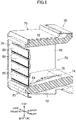
- the casing (33) includes: a first casing (51) in which the heat exchanger (31) and the fan (32) are disposed; and a second casing (71) having the blow-out passage (73) and the air outlet (75), and fitted to the first casing (51).
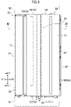
- the first back panel (56) of this body unit (50) has the air inlet (60), and the first front panel (55) opposed to the first back panel (56) has an air outflow port (59).
- the body unit (50) has therein an air passage (61) extending from the air inlet (60) to the air outflow port (59).
- the air passage (61) in the body unit (50) houses the indoor heat exchanger (31), the indoor fan (32), and the drain pan (35).
- the indoor heat exchanger (31) is disposed in a portion of the air passage (61) located on the leeward side of the indoor fan (32) and between the air inlet (60) and the air outflow port (59).
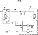
- the air conditioner (10) selectively performs cooling operation and heating operation.
- the airflow direction adjusting flap (85) is simply provided at the air outlet (75) without the provision of a passage through which air is straightened. In that case, even if the angle of the air blown is set at an upward angle, the air that has passed through the indoor air (31) tends to be diffused. Thus, the air blown out of the indoor air (31) hardly reaches a region far away from the indoor unit. This makes it difficult for conditioned air to circulate through the room.
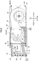
- the blow-out passage (73) is disposed downstream of the outer peripheral portion (37) of the drain pan (35) in the airflow direction. According to this configuration, the air that has passed through the heat exchanger (31) passes through the outer peripheral portion (37) of the drain pan (35), and then flows into the blow-out passage (73). This facilitates straightening the air on the downstream side of the heat exchanger (31) through the blow-out passage (73).
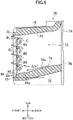
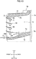
- the second lower end (77) is located below the first lower end (76), and the height of the second lower end (77) of the bottom surface (78) of the blow-out passage (73) is greater than that of the lowermost end of the downstream bottom portion (78a).
- This relationship in height allows air flowing along the bottom surface (78) of the blow-out passage (73) to flow downward through the blow-out passage (73), and then allows the flow of the air to be turned upward by the blow-out surface (84b) upon passing of the air through the lowermost end.
- the air is blown out of the blow-out passage (73).
- the airflow direction is changed smoothly due to the entire bottom surface configured as the curved surface.
- the second lower end (77) may be at the same height as the lowermost end of the downstream bottom portion (78a).
- the blow-out surface (84a) forms a horizontal surface as in the first embodiment.
- Such a configuration also exhibits advantages substantially similar to those of the first variation that is not according to the present invention shown in FIG. 10 .
- the indoor unit (30) including the additional unit (100) can blow conditioned air straightened in the blow-out passage (73) upward, as in the first embodiment. This makes it easy for the conditioned air to reach a region far away from the indoor unit (30), as in the first embodiment. This allows the conditioned air to easily circulate through the room.
Landscapes
- Engineering & Computer Science (AREA)
- Chemical & Material Sciences (AREA)
- Combustion & Propulsion (AREA)
- Mechanical Engineering (AREA)
- General Engineering & Computer Science (AREA)
- Air Filters, Heat-Exchange Apparatuses, And Housings Of Air-Conditioning Units (AREA)
- Devices For Blowing Cold Air, Devices For Blowing Warm Air, And Means For Preventing Water Condensation In Air Conditioning Units (AREA)
- Air-Flow Control Members (AREA)
Claims (8)
- An der Decke hängende Innenraumeinheit einer Klimaanlage, wobei die Innenraumeinheit Folgendes umfasst:ein Gehäuse (33), das eine Vielzahl von Seitenplatten (34) einschließt, wobei eine der Seitenplatten (34) einen Luftauslass (75) aufweist;einen Wärmetauscher (31), der in dem Gehäuse (33) angeordnet ist;ein Gebläse (32), das ausgelegt ist, um Luft, die durch den Wärmetauscher (31) hindurchgelaufen ist, aus dem Luftauslass (75) zu einer zugeordneten Seite des Gehäuses (33) zu blasen;eine am Luftauslass (75) bereitgestellte Klappe (85) zum Anpassen der Luftstromrichtung; undeinen Ausblasdurchgang (73), der sich vom Wärmetauscher (31) zum Luftauslass (75) erstreckt,wobei der Ausblasdurchgang (73) Folgendes aufweist:ein erstes unteres Ende (76), das ein unteres Ende eines von Endabschnitten des Ausblasdurchgangs (73) in der Nähe des Wärmetauschers (31) darstellt, in den die Luft strömt,ein zweites unteres Ende (77), das ein unteres Ende des anderen Endabschnitts des Ausblasdurchgangs (73) in der Nähe des Luftauslasses (75) darstellt, aus dem Luft strömt, wobei sich das zweite untere Ende (77) in einer Höhenrichtung unterhalb des ersten unteren Endes (76) befindet, undeine untere Oberfläche (78), die sich an einem Boden des Ausblasdurchgangs (73) befindet, dadurch gekennzeichnet, dassdie untere Oberfläche (78) des Ausblasdurchgangs (73) Folgendes einschließt:einen geneigten Abschnitt (83), der an einem Endabschnitt in der Nähe des Luftauslasses (75) ausgebildet ist und in einer Richtung geneigt ist, die es ermöglicht, dass sich eine Fläche einer Öffnung des Luftauslasses (75) erhöht, undeine horizontale Ausblasoberfläche (84a), die sich in einer Luftstromrichtung weiter stromaufwärts als der geneigte Abschnitt (83) und angrenzend an den geneigten Abschnitt (83) befindet,wobei die Klappe (85) zum Anpassen der Luftstromrichtung in der Lage ist, die aus dem Ausblasdurchgang (73) strömende Luft relativ zu einer horizontalen Ebene nach oben zu lenken.
- Innenraumeinheit nach Anspruch 1, weiter umfassendeine Ablaufwanne (35) zur Aufnahme von im Wärmetauscher (31) erzeugtem Ablaufwasser, wobei die Ablaufwanne (35) im Gehäuse (33) angeordnet ist, wobeider Ausblasdurchgang (73) stromabwärts eines Außenumfangsabschnitts (37) der Ablaufwanne (35) in der Luftstromrichtung angeordnet ist.
- Innenraumeinheit nach einem der Ansprüche 1 oder 2, wobei
die Klappe (85) zum Anpassen der Luftstromrichtung, welche die Luft relativ zur horizontalen Ebene nach oben lenkt, eine flache obere Oberfläche aufweist. - Innenraumeinheit nach einem der Ansprüche 1 bis 3, wobeidie Klappe (85) zum Anpassen der Luftstromrichtung eine Vielzahl von Schaufelelementen (86) umfasst, die sich in einer Richtung erstrecken, die sich mit einer Richtung von durch den Ausblasdurchgang (73) strömender Luft kreuzt und sich mit einer vertikalen Richtung kreuzt, unddie Schaufelelemente (86) vertikal angeordnet sind.
- Innenraumeinheit nach einem der Ansprüche 1 bis 4, wobei
ein Winkelbereich, in dem die Klappe (85) zum Anpassen der Luftstromrichtung in der Lage ist, die Luft relativ zur horizontalen Ebene nach oben zu lenken, größer als 0° und weniger als oder gleich 10° ist, wobei die horizontale Ebene einen Winkel von 0° aufweist. - Innenraumeinheit nach einem der Ansprüche 1 bis 5, wobeieine Wandoberfläche, die den Ausblasdurchgang (73) definiert, einen überhängenden Abschnitt (80a) aufweist, der einem oberen Abschnitt einer stromabwärtigen Öffnung des Ausblasdurchgangs (73) in einer Luftstromrichtung entspricht und nach unten überhängt, undder überhängende Abschnitt (80a) sich in eine Richtung erstreckt, die sich mit einer Richtung von durch den Ausblasdurchgang (73) strömender Luft kreuzt und sich mit einer vertikalen Richtung kreuzt.
- Innenraumeinheit nach einem der Ansprüche 1 bis 6, wobei
eine andere (56) der Seitenplatten des Gehäuses (33), die der einen (81) der Seitenplatten, die den Luftauslass (75) aufweist, gegenüberliegt, einen Lufteinlass (60) aufweist. - Innenraumeinheit nach einem der Ansprüche 1 bis 7, wobei
das Gehäuses (33) Folgendes einschließt:ein erstes Gehäuse (51), in dem der Wärmetauscher (31) und das Gebläse (32) angeordnet sind; undein zweites Gehäuse (71), das den Ausblasdurchgang (73) und den Luftauslass (75) aufweist und an dem ersten Gehäuse (51) angebracht ist.
Applications Claiming Priority (2)
| Application Number | Priority Date | Filing Date | Title |
|---|---|---|---|
| JP2018224565A JP6904324B2 (ja) | 2018-11-30 | 2018-11-30 | 空気調和装置の室内機 |
| PCT/JP2019/039390 WO2020110462A1 (ja) | 2018-11-30 | 2019-10-04 | 空気調和装置の室内機 |
Publications (3)
| Publication Number | Publication Date |
|---|---|
| EP3885667A1 EP3885667A1 (de) | 2021-09-29 |
| EP3885667A4 EP3885667A4 (de) | 2022-01-19 |
| EP3885667B1 true EP3885667B1 (de) | 2023-01-25 |
Family
ID=70853374
Family Applications (1)
| Application Number | Title | Priority Date | Filing Date |
|---|---|---|---|
| EP19888699.6A Active EP3885667B1 (de) | 2018-11-30 | 2019-10-04 | Innenraumeinheit einer klimaanlage |
Country Status (4)
| Country | Link |
|---|---|
| EP (1) | EP3885667B1 (de) |
| JP (1) | JP6904324B2 (de) |
| CN (1) | CN216204236U (de) |
| WO (1) | WO2020110462A1 (de) |
Families Citing this family (1)
| Publication number | Priority date | Publication date | Assignee | Title |
|---|---|---|---|---|
| WO2025246093A1 (zh) * | 2024-05-28 | 2025-12-04 | 美的集团武汉暖通设备有限公司 | 空调器 |
Family Cites Families (11)
| Publication number | Priority date | Publication date | Assignee | Title |
|---|---|---|---|---|
| WO1983004290A1 (en) * | 1982-05-25 | 1983-12-08 | Matsushita Electric Industrial Co., Ltd. | Direction-of-flow controller |
| JPH0720502Y2 (ja) * | 1988-10-28 | 1995-05-15 | 三洋電機株式会社 | 空気調和装置 |
| JPH08327083A (ja) * | 1995-06-06 | 1996-12-10 | Mitsubishi Heavy Ind Ltd | 天井吊り下げ型空気調和機 |
| JP2993412B2 (ja) * | 1995-11-20 | 1999-12-20 | 三菱電機株式会社 | 吹出口及び該吹出口を備えた空気調和装置 |
| JP3765357B2 (ja) * | 1997-06-20 | 2006-04-12 | 株式会社富士通ゼネラル | 空気調和機 |
| JP3885845B2 (ja) * | 1998-03-16 | 2007-02-28 | 株式会社富士通ゼネラル | 空気調和機 |
| JP2991189B1 (ja) * | 1998-06-29 | 1999-12-20 | 松下電器産業株式会社 | 空気調和機 |
| JP4544364B1 (ja) | 2009-04-17 | 2010-09-15 | ダイキン工業株式会社 | 空気調和装置 |
| JP5403084B2 (ja) * | 2012-02-10 | 2014-01-29 | ダイキン工業株式会社 | 室内機 |
| JP6163182B2 (ja) * | 2015-08-25 | 2017-07-12 | 豊和化成株式会社 | 薄型レジスタ |
| JP6468303B2 (ja) * | 2017-02-24 | 2019-02-13 | ダイキン工業株式会社 | 空気調和装置の室内機 |
-
2018
- 2018-11-30 JP JP2018224565A patent/JP6904324B2/ja active Active
-
2019
- 2019-10-04 WO PCT/JP2019/039390 patent/WO2020110462A1/ja not_active Ceased
- 2019-10-04 CN CN201990001197.7U patent/CN216204236U/zh active Active
- 2019-10-04 EP EP19888699.6A patent/EP3885667B1/de active Active
Also Published As
| Publication number | Publication date |
|---|---|
| EP3885667A4 (de) | 2022-01-19 |
| CN216204236U (zh) | 2022-04-05 |
| JP6904324B2 (ja) | 2021-07-14 |
| EP3885667A1 (de) | 2021-09-29 |
| JP2020085401A (ja) | 2020-06-04 |
| WO2020110462A1 (ja) | 2020-06-04 |
Similar Documents
| Publication | Publication Date | Title |
|---|---|---|
| US11067298B2 (en) | Air conditioner | |
| CN109891155B (zh) | 室内机及空调装置 | |
| KR20180044162A (ko) | 공기조화기 | |
| KR20090038555A (ko) | 토출풍향 제어장치를 구비한 공기조화기 | |
| CN104024759B (zh) | 空气调节机 | |
| EP3412984B1 (de) | Innenraumeinheit für klimaanlagen | |
| EP2985542A1 (de) | Dekorative platte und klimaanlage in einer raumeinheit damit | |
| KR20180039405A (ko) | 공기조화기 | |
| CN107278256A (zh) | 空调的室内机 | |
| JP2004116859A (ja) | 空気調和機 | |
| KR101577071B1 (ko) | 공기조화장치의 실내기 | |
| CN114729758B (zh) | 具有补充空气模块的空调设备 | |
| CN110573805A (zh) | 空调机 | |
| CN211041167U (zh) | 空调装置的室内机 | |
| CN110392806B (zh) | 空调机的室内机 | |
| KR20190012841A (ko) | 공기조화기 | |
| EP3885667A1 (de) | Innenraumeinheit einer klimaanlage | |
| CN107490108A (zh) | 一种带恒温恒湿柜的空调机 | |
| KR20190051676A (ko) | 공기조화기의 실내기 | |
| KR20220104557A (ko) | 공기조화기 | |
| EP1970638A1 (de) | Klimaanlage | |
| KR20040015872A (ko) | 액자형 공기조화기 | |
| CN219868151U (zh) | 挂式空调室内机 | |
| CN113757812B (zh) | 窗式空调器 | |
| CN219841592U (zh) | 挂式空调室内机 |
Legal Events
| Date | Code | Title | Description |
|---|---|---|---|
| STAA | Information on the status of an ep patent application or granted ep patent |
Free format text: STATUS: THE INTERNATIONAL PUBLICATION HAS BEEN MADE |
|
| PUAI | Public reference made under article 153(3) epc to a published international application that has entered the european phase |
Free format text: ORIGINAL CODE: 0009012 |
|
| STAA | Information on the status of an ep patent application or granted ep patent |
Free format text: STATUS: REQUEST FOR EXAMINATION WAS MADE |
|
| 17P | Request for examination filed |
Effective date: 20210622 |
|
| AK | Designated contracting states |
Kind code of ref document: A1 Designated state(s): AL AT BE BG CH CY CZ DE DK EE ES FI FR GB GR HR HU IE IS IT LI LT LU LV MC MK MT NL NO PL PT RO RS SE SI SK SM TR |
|
| A4 | Supplementary search report drawn up and despatched |
Effective date: 20211217 |
|
| RIC1 | Information provided on ipc code assigned before grant |
Ipc: F24F 13/14 20060101ALI20211213BHEP Ipc: F24F 1/0011 20190101ALI20211213BHEP Ipc: F24F 13/22 20060101ALI20211213BHEP Ipc: F24F 1/0047 20190101ALI20211213BHEP Ipc: F24F 13/20 20060101AFI20211213BHEP |
|
| DAV | Request for validation of the european patent (deleted) | ||
| DAX | Request for extension of the european patent (deleted) | ||
| GRAP | Despatch of communication of intention to grant a patent |
Free format text: ORIGINAL CODE: EPIDOSNIGR1 |
|
| STAA | Information on the status of an ep patent application or granted ep patent |
Free format text: STATUS: GRANT OF PATENT IS INTENDED |
|
| RIC1 | Information provided on ipc code assigned before grant |
Ipc: F24F 13/14 20060101ALI20220824BHEP Ipc: F24F 1/0011 20190101ALI20220824BHEP Ipc: F24F 13/22 20060101ALI20220824BHEP Ipc: F24F 1/0047 20190101ALI20220824BHEP Ipc: F24F 13/20 20060101AFI20220824BHEP |
|
| INTG | Intention to grant announced |
Effective date: 20220920 |
|
| RIN1 | Information on inventor provided before grant (corrected) |
Inventor name: NAKAYAMA, TOSHIMICHI Inventor name: SHIOHAMA, KOUSUKE Inventor name: SUHARA, RYOUTA Inventor name: KIMURA, TSUYOSHI |
|
| GRAS | Grant fee paid |
Free format text: ORIGINAL CODE: EPIDOSNIGR3 |
|
| GRAA | (expected) grant |
Free format text: ORIGINAL CODE: 0009210 |
|
| STAA | Information on the status of an ep patent application or granted ep patent |
Free format text: STATUS: THE PATENT HAS BEEN GRANTED |
|
| RAP3 | Party data changed (applicant data changed or rights of an application transferred) |
Owner name: DAIKIN INDUSTRIES, LTD. |
|
| AK | Designated contracting states |
Kind code of ref document: B1 Designated state(s): AL AT BE BG CH CY CZ DE DK EE ES FI FR GB GR HR HU IE IS IT LI LT LU LV MC MK MT NL NO PL PT RO RS SE SI SK SM TR |
|
| REG | Reference to a national code |
Ref country code: GB Ref legal event code: FG4D |
|
| REG | Reference to a national code |
Ref country code: CH Ref legal event code: EP |
|
| REG | Reference to a national code |
Ref country code: AT Ref legal event code: REF Ref document number: 1546161 Country of ref document: AT Kind code of ref document: T Effective date: 20230215 Ref country code: IE Ref legal event code: FG4D |
|
| REG | Reference to a national code |
Ref country code: DE Ref legal event code: R096 Ref document number: 602019024960 Country of ref document: DE |
|
| REG | Reference to a national code |
Ref country code: LT Ref legal event code: MG9D |
|
| REG | Reference to a national code |
Ref country code: NL Ref legal event code: MP Effective date: 20230125 |
|
| REG | Reference to a national code |
Ref country code: AT Ref legal event code: MK05 Ref document number: 1546161 Country of ref document: AT Kind code of ref document: T Effective date: 20230125 |
|
| PG25 | Lapsed in a contracting state [announced via postgrant information from national office to epo] |
Ref country code: NL Free format text: LAPSE BECAUSE OF FAILURE TO SUBMIT A TRANSLATION OF THE DESCRIPTION OR TO PAY THE FEE WITHIN THE PRESCRIBED TIME-LIMIT Effective date: 20230125 |
|
| P01 | Opt-out of the competence of the unified patent court (upc) registered |
Effective date: 20230525 |
|
| PG25 | Lapsed in a contracting state [announced via postgrant information from national office to epo] |
Ref country code: RS Free format text: LAPSE BECAUSE OF FAILURE TO SUBMIT A TRANSLATION OF THE DESCRIPTION OR TO PAY THE FEE WITHIN THE PRESCRIBED TIME-LIMIT Effective date: 20230125 Ref country code: PT Free format text: LAPSE BECAUSE OF FAILURE TO SUBMIT A TRANSLATION OF THE DESCRIPTION OR TO PAY THE FEE WITHIN THE PRESCRIBED TIME-LIMIT Effective date: 20230525 Ref country code: NO Free format text: LAPSE BECAUSE OF FAILURE TO SUBMIT A TRANSLATION OF THE DESCRIPTION OR TO PAY THE FEE WITHIN THE PRESCRIBED TIME-LIMIT Effective date: 20230425 Ref country code: LV Free format text: LAPSE BECAUSE OF FAILURE TO SUBMIT A TRANSLATION OF THE DESCRIPTION OR TO PAY THE FEE WITHIN THE PRESCRIBED TIME-LIMIT Effective date: 20230125 Ref country code: LT Free format text: LAPSE BECAUSE OF FAILURE TO SUBMIT A TRANSLATION OF THE DESCRIPTION OR TO PAY THE FEE WITHIN THE PRESCRIBED TIME-LIMIT Effective date: 20230125 Ref country code: HR Free format text: LAPSE BECAUSE OF FAILURE TO SUBMIT A TRANSLATION OF THE DESCRIPTION OR TO PAY THE FEE WITHIN THE PRESCRIBED TIME-LIMIT Effective date: 20230125 Ref country code: ES Free format text: LAPSE BECAUSE OF FAILURE TO SUBMIT A TRANSLATION OF THE DESCRIPTION OR TO PAY THE FEE WITHIN THE PRESCRIBED TIME-LIMIT Effective date: 20230125 Ref country code: AT Free format text: LAPSE BECAUSE OF FAILURE TO SUBMIT A TRANSLATION OF THE DESCRIPTION OR TO PAY THE FEE WITHIN THE PRESCRIBED TIME-LIMIT Effective date: 20230125 |
|
| PG25 | Lapsed in a contracting state [announced via postgrant information from national office to epo] |
Ref country code: SE Free format text: LAPSE BECAUSE OF FAILURE TO SUBMIT A TRANSLATION OF THE DESCRIPTION OR TO PAY THE FEE WITHIN THE PRESCRIBED TIME-LIMIT Effective date: 20230125 Ref country code: PL Free format text: LAPSE BECAUSE OF FAILURE TO SUBMIT A TRANSLATION OF THE DESCRIPTION OR TO PAY THE FEE WITHIN THE PRESCRIBED TIME-LIMIT Effective date: 20230125 Ref country code: IS Free format text: LAPSE BECAUSE OF FAILURE TO SUBMIT A TRANSLATION OF THE DESCRIPTION OR TO PAY THE FEE WITHIN THE PRESCRIBED TIME-LIMIT Effective date: 20230525 Ref country code: GR Free format text: LAPSE BECAUSE OF FAILURE TO SUBMIT A TRANSLATION OF THE DESCRIPTION OR TO PAY THE FEE WITHIN THE PRESCRIBED TIME-LIMIT Effective date: 20230426 Ref country code: FI Free format text: LAPSE BECAUSE OF FAILURE TO SUBMIT A TRANSLATION OF THE DESCRIPTION OR TO PAY THE FEE WITHIN THE PRESCRIBED TIME-LIMIT Effective date: 20230125 |
|
| REG | Reference to a national code |
Ref country code: DE Ref legal event code: R097 Ref document number: 602019024960 Country of ref document: DE |
|
| PG25 | Lapsed in a contracting state [announced via postgrant information from national office to epo] |
Ref country code: SM Free format text: LAPSE BECAUSE OF FAILURE TO SUBMIT A TRANSLATION OF THE DESCRIPTION OR TO PAY THE FEE WITHIN THE PRESCRIBED TIME-LIMIT Effective date: 20230125 Ref country code: RO Free format text: LAPSE BECAUSE OF FAILURE TO SUBMIT A TRANSLATION OF THE DESCRIPTION OR TO PAY THE FEE WITHIN THE PRESCRIBED TIME-LIMIT Effective date: 20230125 Ref country code: EE Free format text: LAPSE BECAUSE OF FAILURE TO SUBMIT A TRANSLATION OF THE DESCRIPTION OR TO PAY THE FEE WITHIN THE PRESCRIBED TIME-LIMIT Effective date: 20230125 Ref country code: DK Free format text: LAPSE BECAUSE OF FAILURE TO SUBMIT A TRANSLATION OF THE DESCRIPTION OR TO PAY THE FEE WITHIN THE PRESCRIBED TIME-LIMIT Effective date: 20230125 Ref country code: CZ Free format text: LAPSE BECAUSE OF FAILURE TO SUBMIT A TRANSLATION OF THE DESCRIPTION OR TO PAY THE FEE WITHIN THE PRESCRIBED TIME-LIMIT Effective date: 20230125 |
|
| PG25 | Lapsed in a contracting state [announced via postgrant information from national office to epo] |
Ref country code: SK Free format text: LAPSE BECAUSE OF FAILURE TO SUBMIT A TRANSLATION OF THE DESCRIPTION OR TO PAY THE FEE WITHIN THE PRESCRIBED TIME-LIMIT Effective date: 20230125 |
|
| PLBE | No opposition filed within time limit |
Free format text: ORIGINAL CODE: 0009261 |
|
| STAA | Information on the status of an ep patent application or granted ep patent |
Free format text: STATUS: NO OPPOSITION FILED WITHIN TIME LIMIT |
|
| 26N | No opposition filed |
Effective date: 20231026 |
|
| PG25 | Lapsed in a contracting state [announced via postgrant information from national office to epo] |
Ref country code: SI Free format text: LAPSE BECAUSE OF FAILURE TO SUBMIT A TRANSLATION OF THE DESCRIPTION OR TO PAY THE FEE WITHIN THE PRESCRIBED TIME-LIMIT Effective date: 20230125 |
|
| PG25 | Lapsed in a contracting state [announced via postgrant information from national office to epo] |
Ref country code: IT Free format text: LAPSE BECAUSE OF FAILURE TO SUBMIT A TRANSLATION OF THE DESCRIPTION OR TO PAY THE FEE WITHIN THE PRESCRIBED TIME-LIMIT Effective date: 20230125 Ref country code: MC Free format text: LAPSE BECAUSE OF FAILURE TO SUBMIT A TRANSLATION OF THE DESCRIPTION OR TO PAY THE FEE WITHIN THE PRESCRIBED TIME-LIMIT Effective date: 20230125 |
|
| REG | Reference to a national code |
Ref country code: CH Ref legal event code: PL |
|
| REG | Reference to a national code |
Ref country code: BE Ref legal event code: MM Effective date: 20231031 |
|
| PG25 | Lapsed in a contracting state [announced via postgrant information from national office to epo] |
Ref country code: LU Free format text: LAPSE BECAUSE OF NON-PAYMENT OF DUE FEES Effective date: 20231004 |
|
| PG25 | Lapsed in a contracting state [announced via postgrant information from national office to epo] |
Ref country code: LU Free format text: LAPSE BECAUSE OF NON-PAYMENT OF DUE FEES Effective date: 20231004 |
|
| PG25 | Lapsed in a contracting state [announced via postgrant information from national office to epo] |
Ref country code: CH Free format text: LAPSE BECAUSE OF NON-PAYMENT OF DUE FEES Effective date: 20231031 |
|
| PG25 | Lapsed in a contracting state [announced via postgrant information from national office to epo] |
Ref country code: CH Free format text: LAPSE BECAUSE OF NON-PAYMENT OF DUE FEES Effective date: 20231031 |
|
| PG25 | Lapsed in a contracting state [announced via postgrant information from national office to epo] |
Ref country code: BE Free format text: LAPSE BECAUSE OF NON-PAYMENT OF DUE FEES Effective date: 20231031 |
|
| PG25 | Lapsed in a contracting state [announced via postgrant information from national office to epo] |
Ref country code: IE Free format text: LAPSE BECAUSE OF NON-PAYMENT OF DUE FEES Effective date: 20231004 |
|
| PG25 | Lapsed in a contracting state [announced via postgrant information from national office to epo] |
Ref country code: IE Free format text: LAPSE BECAUSE OF NON-PAYMENT OF DUE FEES Effective date: 20231004 |
|
| PG25 | Lapsed in a contracting state [announced via postgrant information from national office to epo] |
Ref country code: BG Free format text: LAPSE BECAUSE OF FAILURE TO SUBMIT A TRANSLATION OF THE DESCRIPTION OR TO PAY THE FEE WITHIN THE PRESCRIBED TIME-LIMIT Effective date: 20230125 |
|
| PG25 | Lapsed in a contracting state [announced via postgrant information from national office to epo] |
Ref country code: BG Free format text: LAPSE BECAUSE OF FAILURE TO SUBMIT A TRANSLATION OF THE DESCRIPTION OR TO PAY THE FEE WITHIN THE PRESCRIBED TIME-LIMIT Effective date: 20230125 |
|
| PG25 | Lapsed in a contracting state [announced via postgrant information from national office to epo] |
Ref country code: CY Free format text: LAPSE BECAUSE OF FAILURE TO SUBMIT A TRANSLATION OF THE DESCRIPTION OR TO PAY THE FEE WITHIN THE PRESCRIBED TIME-LIMIT; INVALID AB INITIO Effective date: 20191004 |
|
| PG25 | Lapsed in a contracting state [announced via postgrant information from national office to epo] |
Ref country code: HU Free format text: LAPSE BECAUSE OF FAILURE TO SUBMIT A TRANSLATION OF THE DESCRIPTION OR TO PAY THE FEE WITHIN THE PRESCRIBED TIME-LIMIT; INVALID AB INITIO Effective date: 20191004 |
|
| PGFP | Annual fee paid to national office [announced via postgrant information from national office to epo] |
Ref country code: GB Payment date: 20250828 Year of fee payment: 7 |
|
| PGFP | Annual fee paid to national office [announced via postgrant information from national office to epo] |
Ref country code: FR Payment date: 20250908 Year of fee payment: 7 |
|
| PG25 | Lapsed in a contracting state [announced via postgrant information from national office to epo] |
Ref country code: TR Free format text: LAPSE BECAUSE OF FAILURE TO SUBMIT A TRANSLATION OF THE DESCRIPTION OR TO PAY THE FEE WITHIN THE PRESCRIBED TIME-LIMIT Effective date: 20230125 |
|
| PGFP | Annual fee paid to national office [announced via postgrant information from national office to epo] |
Ref country code: DE Payment date: 20250902 Year of fee payment: 7 |