EP3885771B1 - Procédé et système pour réidentifier des transporteurs sur un système de transport de laboratoire - Google Patents
Procédé et système pour réidentifier des transporteurs sur un système de transport de laboratoire Download PDFInfo
- Publication number
- EP3885771B1 EP3885771B1 EP20165745.9A EP20165745A EP3885771B1 EP 3885771 B1 EP3885771 B1 EP 3885771B1 EP 20165745 A EP20165745 A EP 20165745A EP 3885771 B1 EP3885771 B1 EP 3885771B1
- Authority
- EP
- European Patent Office
- Prior art keywords
- carrier
- transport
- identity
- laboratory
- positions
- Prior art date
- Legal status (The legal status is an assumption and is not a legal conclusion. Google has not performed a legal analysis and makes no representation as to the accuracy of the status listed.)
- Active
Links
Images


Classifications
-
- G—PHYSICS
- G01—MEASURING; TESTING
- G01N—INVESTIGATING OR ANALYSING MATERIALS BY DETERMINING THEIR CHEMICAL OR PHYSICAL PROPERTIES
- G01N35/00—Automatic analysis not limited to methods or materials provided for in any single one of groups G01N1/00 - G01N33/00; Handling materials therefor
- G01N35/02—Automatic analysis not limited to methods or materials provided for in any single one of groups G01N1/00 - G01N33/00; Handling materials therefor using a plurality of sample containers moved by a conveyor system past one or more treatment or analysis stations
- G01N35/04—Details of the conveyor system
-
- G—PHYSICS
- G01—MEASURING; TESTING
- G01N—INVESTIGATING OR ANALYSING MATERIALS BY DETERMINING THEIR CHEMICAL OR PHYSICAL PROPERTIES
- G01N35/00—Automatic analysis not limited to methods or materials provided for in any single one of groups G01N1/00 - G01N33/00; Handling materials therefor
- G01N35/00584—Control arrangements for automatic analysers
- G01N35/00722—Communications; Identification
- G01N35/00732—Identification of carriers, materials or components in automatic analysers
-
- G—PHYSICS
- G01—MEASURING; TESTING
- G01N—INVESTIGATING OR ANALYSING MATERIALS BY DETERMINING THEIR CHEMICAL OR PHYSICAL PROPERTIES
- G01N35/00—Automatic analysis not limited to methods or materials provided for in any single one of groups G01N1/00 - G01N33/00; Handling materials therefor
- G01N35/00584—Control arrangements for automatic analysers
- G01N35/00594—Quality control, including calibration or testing of components of the analyser
- G01N35/00613—Quality control
- G01N35/00623—Quality control of instruments
-
- G—PHYSICS
- G01—MEASURING; TESTING
- G01N—INVESTIGATING OR ANALYSING MATERIALS BY DETERMINING THEIR CHEMICAL OR PHYSICAL PROPERTIES
- G01N35/00—Automatic analysis not limited to methods or materials provided for in any single one of groups G01N1/00 - G01N33/00; Handling materials therefor
- G01N35/00584—Control arrangements for automatic analysers
- G01N35/00722—Communications; Identification
- G01N35/00732—Identification of carriers, materials or components in automatic analysers
- G01N2035/00742—Type of codes
- G01N2035/00752—Type of codes bar codes
-
- G—PHYSICS
- G01—MEASURING; TESTING
- G01N—INVESTIGATING OR ANALYSING MATERIALS BY DETERMINING THEIR CHEMICAL OR PHYSICAL PROPERTIES
- G01N35/00—Automatic analysis not limited to methods or materials provided for in any single one of groups G01N1/00 - G01N33/00; Handling materials therefor
- G01N35/00584—Control arrangements for automatic analysers
- G01N35/00722—Communications; Identification
- G01N35/00732—Identification of carriers, materials or components in automatic analysers
- G01N2035/00792—Type of components bearing the codes, other than sample carriers
- G01N2035/00801—Holders for sample carriers, e.g. trays, caroussel, racks
-
- G—PHYSICS
- G01—MEASURING; TESTING
- G01N—INVESTIGATING OR ANALYSING MATERIALS BY DETERMINING THEIR CHEMICAL OR PHYSICAL PROPERTIES
- G01N35/00—Automatic analysis not limited to methods or materials provided for in any single one of groups G01N1/00 - G01N33/00; Handling materials therefor
- G01N35/02—Automatic analysis not limited to methods or materials provided for in any single one of groups G01N1/00 - G01N33/00; Handling materials therefor using a plurality of sample containers moved by a conveyor system past one or more treatment or analysis stations
- G01N35/04—Details of the conveyor system
- G01N2035/0401—Sample carriers, cuvettes or reaction vessels
- G01N2035/0406—Individual bottles or tubes
-
- G—PHYSICS
- G01—MEASURING; TESTING
- G01N—INVESTIGATING OR ANALYSING MATERIALS BY DETERMINING THEIR CHEMICAL OR PHYSICAL PROPERTIES
- G01N35/00—Automatic analysis not limited to methods or materials provided for in any single one of groups G01N1/00 - G01N33/00; Handling materials therefor
- G01N35/02—Automatic analysis not limited to methods or materials provided for in any single one of groups G01N1/00 - G01N33/00; Handling materials therefor using a plurality of sample containers moved by a conveyor system past one or more treatment or analysis stations
- G01N35/04—Details of the conveyor system
- G01N2035/0474—Details of actuating means for conveyors or pipettes
- G01N2035/0477—Magnetic
-
- G—PHYSICS
- G01—MEASURING; TESTING
- G01N—INVESTIGATING OR ANALYSING MATERIALS BY DETERMINING THEIR CHEMICAL OR PHYSICAL PROPERTIES
- G01N35/00—Automatic analysis not limited to methods or materials provided for in any single one of groups G01N1/00 - G01N33/00; Handling materials therefor
- G01N35/02—Automatic analysis not limited to methods or materials provided for in any single one of groups G01N1/00 - G01N33/00; Handling materials therefor using a plurality of sample containers moved by a conveyor system past one or more treatment or analysis stations
- G01N35/04—Details of the conveyor system
- G01N2035/0474—Details of actuating means for conveyors or pipettes
- G01N2035/0491—Position sensing, encoding; closed-loop control
- G01N2035/0493—Locating samples; identifying different tube sizes
-
- G—PHYSICS
- G01—MEASURING; TESTING
- G01N—INVESTIGATING OR ANALYSING MATERIALS BY DETERMINING THEIR CHEMICAL OR PHYSICAL PROPERTIES
- G01N35/00—Automatic analysis not limited to methods or materials provided for in any single one of groups G01N1/00 - G01N33/00; Handling materials therefor
- G01N35/00584—Control arrangements for automatic analysers
- G01N35/00722—Communications; Identification
Definitions
- the present disclosure belongs to the field of automated in vitro diagnostic laboratory testing. Within this field, it relates to a method, a laboratory transport system, a computer program product, and a computer-readable storage medium to re-identify carriers on a laboratory transport system after a system failure.
- test sample vessels like test sample vessels, test reagent containers, or test consumable containers are transported between multiple stations such as pre- analytical, analytical and post- analytical stations according to predefined laboratory workflows.
- vessels and containers are transported in carriers.
- the carriers are moved on a transport plane of a laboratory transport system in order to distribute the vessels and containers to connected pre- analytical, analytical and post- analytical stations which can conduct different sample processing steps like preparing, analysing, or archiving of test samples.
- EP2566787B1 discloses a laboratory transport system and identifying means such as RFID readers for identifying and localizing a carrier on a laboratory transport system based on triangulation.
- US9567167B2 discloses a laboratory transport system and a monitoring system for detecting positions of respective carriers on the transport plane.
- US9567167B2 further discloses that after a switch of carrier positions, the control unit issues an error message for manual inspection.
- the control unit issues an error message for manual inspection.
- EP 3 349 015 A1 discloses a method to identify a carrier on a laboratory transport system, wherein in case of power down of the system, the sensed position is stored and compared when powering up the system.
- US2017/0283845 A1 discloses a laboratory system capable of tracking precise locations of one or more components of the laboratory system.
- the present disclosure refers to a method, a laboratory transport system, a computer program product, and a computer-readable storage medium to re-identify a carrier on the laboratory transport system.
- the present disclosure relates to a method to re-identify a carrier on a laboratory transport system.
- the carrier is associated with an identity and the carrier is configured to move over a transport plane of the laboratory transport system.
- the laboratory transport system comprises a monitoring system configured to monitor motion positions of the carrier on the transport plane when the laboratory transport system is activated.
- the laboratory transport system comprises a control unit and the method comprises the following steps:
- the present disclosure also relates to a laboratory transport system according to claim 13.
- the present disclosure further relates to a computer program product comprising instructions to cause the laboratory transport system as described herein to execute the steps of the method to re-identify a carrier on the laboratory transport system as described herein.
- the present disclosure further relates to a computer-readable storage medium having stored thereon the computer program product comprising instructions to cause the laboratory transport system as described herein to execute the steps of the method to re-identify a carrier on the laboratory transport system as described herein.
- the present disclosure relates to a method to re-identify a carrier on a laboratory transport system.
- the carrier is associated with an identity and the carrier is configured to move over a transport plane of the laboratory transport system.
- the laboratory transport system comprises a monitoring system configured to monitor motion positions of the carrier on the transport plane when the laboratory transport system is activated.
- the laboratory transport system comprises a control unit and the method comprises the following steps:
- carrier relates to a device configured for receiving, holding, transporting, and/or releasing a payload such as a test sample vessel, test reagent container, or test consumable container.
- a test sample vessel is configured for receiving, holding, transporting, and/or releasing a test sample or a mixture of a test sample and test reagent.
- a test reagent container is configured for receiving, holding, transporting, and/or releasing a test reagent.
- a test consumable container is configured for receiving, holding, transporting, and/or releasing a test consumable such as, as non-limiting example, pipetting tips.
- the test sample vessel, test reagent container, or test consumable container is inserted into a holder of the carrier.
- the carrier comprises at least one magnetically active device which interacts with a magnetic field so that a magnetic force is applied to the carrier in order to move the carrier on the transport plane.
- the carrier further comprises a bottom plate on which the carrier slides over the transport plane of the laboratory transport system.
- a carrier comprising at least one magnetically active device which interacts with a magnetic field and a bottom plate for sliding over the transport plane is well known in the art and may be designed as described in EP2988134A1 reference number 10 in figure 1 and corresponding description or as described in EP3070479A1 reference 1 in figures 1 , 2 , and 3 and corresponding description.
- the carrier is associated with an identity.
- identity relates to an identifier for the distinct identification of a carrier and/ or its payload. Thus, the identity may depend on the payload of the carrier.
- the identity relates to an identity of a test sample if the carrier holds a test sample vessel containing a test sample.
- identity relates to an identity of a control sample if the carrier holds a control sample vessel containing a control sample.
- the identity relates to an identity of a test reagent if the carrier holds a test reagent container containing a test reagent.
- the identity relates to an identity of a consumable if the carrier holds a consumable container containing a consumable.
- the identity is a carrier identity if the carrier does not hold a test sample vessel containing a test sample.
- the identity is also a carrier identity if the carrier does not hold any other payload such as a control sample vessel containing a control sample, a test reagent container containing a test reagent, or consumable container containing a consumable.
- the term "associated or associated identity” means that the identity of a carrier and/ or its payload is assigned or linked to a position of the carrier on the transport plane.
- a carrier and/ or its payload may be provided with a barcode tag or RFID tag comprising the identity of the carrier and/ or its payload.
- the carrier and/ or its payload may be placed at a certain position on the transport plane, e.g. at a starting position.
- a carrier identification unit connected to the laboratory transport system may determine the identity of the carrier and/ or its payload.
- the determined identity of the carrier and/ or its payload is then associated to the carrier by assigning the determined identity of the carrier and/ or its payload to the carrier position on the transport plane.
- the identity of the carrier and/ or its payload may be associated to the carrier by assigning the identity of the carrier and/ or its payload to a position of the carrier on the transport plane in a database record.
- the carrier may be placed on a position on the transport plane and the identity of the carrier and/ or its payload and the carrier position may be entered manually in a cross table of a database. If the carrier moves to an adjacent position on the transport plane, the associated identity is assigned to the adjacent position where the carrier is located. Or in other words, the associated identity moves together with the carrier on the transport plane. Accordingly, the associated identity can be localized on the transport plane just by monitoring motion positions of the carrier on the transport plane without repeated determining of the identity of the carrier and/ or its payload by a carrier identification unit.
- the associated identity is lost or dissociated from the carrier, as soon as no motion positions of the carrier are monitored anymore.
- a system failure causes dissociation of the identity from the carrier.
- the identity is associated with information of the carrier and/ or its payload.
- this information comprises a carrier feature and/ or a payload feature.
- this information relates to information from which a carrier feature and/ or payload feature is derived.
- Carrier and payload features relate to a physical property of the carrier and/ or its payload and may determine the motion behavior of the carrier after a system failure when the carrier keeps moving on the transport plane.
- the identity may be associated with carrier features, such as, as non-limiting examples, carrier weight, carrier dimension and/ geometric form, etc.
- payload features such as, as non-limiting examples, test sample vessel weight, test sample vessel dimension and/ geometric form, test sample volume, test sample weight, etc.
- Information from which a carrier feature or payload feature may be derived are, as non-limiting examples, carrier type, carrier onboard time, payload type, payload expiration date, etc.
- additional information that is relevant for the transportation of the carrier on the laboratory transport system is associated with the identity.
- Such information includes information about ordered test(s) for a test sample, transportation route(s) of a carrier on the transport plane and/or corresponding starting position(s), destination position(s), etc.
- laboratory transport system relates to a system being designed to transport or distribute payloads such as test sample vessels, test reagent containers, or test consumable containers to connected pre- analytical stations, analytical stations, or post-analytical stations of a diagnostic laboratory system.
- a pre-analytical station can usually be used for the preliminary processing of test samples or test sample vessels.
- An analytical station can be designed, for example, to use a test sample or part of the test sample and a test reagent in order to produce a measurable signal, on the basis of which it is possible to determine whether an analyte is present, and if desired in what concentration.
- a post-analytical station is used for the post-processing of test samples or test sample vessels like the archiving of test samples or test sample vessels.
- Such pre-analytical stations, analytical stations, post-analytical stations, and devices are well known in the art.
- the laboratory transport system comprises a transport plane on which carriers can be transported or moved.
- the carrier may move along transportation routes on the transport plane.
- transportation route relates to a path a carrier moves from a starting position to a destination position on the transport plane.
- the carrier may move directly from the starting position to the destination position or via one or more intermediate positions between the starting position and the destination position.
- the transportation route defines the order of intermediate positions the carrier passes on its path from the starting position to the destination position.
- the starting position, the destination position, and the one or more intermediate positions between the starting position and destination position are located at connected pre- analytical, analytical and post- analytical stations so that test sample processing steps according to predefined laboratory workflows are conducted.
- the starting position may be located at a connected pre-analytical station comprising a cap removal/ fitting device for removing the cap from the test sample vessel and/ or a carrier identification unit.
- the destination position may be located at a connected post-analytical station comprising a cap removal/ fitting device for fitting a cap on the test sample vessel and/ or a carrier identification unit.
- the one or more intermediate positions between the starting position and destination position may be located at one or more connected analytical stations where test samples are aspirated out of the test sample vessel for analysis of the test sample.
- the one or more analytical stations comprise a carrier identification unit.
- the one or more intermediate positions may be located at dedicated areas on the transport plane for temporal placing or parking of carriers (buffering areas).
- the laboratory transport system comprises a number of electro-magnetic actuators being stationary arranged below the transport plane and adapted to generate magnetic fields to move the carrier.
- the carrier comprises a magnetically active device which can interact with the magnetic fields so that a magnetic force is applied to the carrier for moving the carrier over the transport plane.
- control unit encompasses any physical or virtual processing device comprising a processor which is configured to re-identify a carrier on a laboratory transport system after a system failure.
- the control unit receives monitored motion positions from the monitoring system and generates log data of the carrier and its associated identity based on the monitored motion positions.
- the control unit predicts the position of the identity based on the generated log data.
- the control unit determines a vector based on the log data, simulates motion positions of the carrier based on the determined vector, and predicts the position of the identity based on the simulated motion positions of the carrier.
- the control unit further receives detected actual positions of the carrier from the monitoring system after reactivation of the laboratory transport system and compares them with the predicted positions of the identity. If the predicted position of the identity matches with the actual position of the carrier, the control unit assigns the identity to the carrier.
- control unit is further configured to receive a determined identity from a carrier identification unit and to assign the determined identity to a carrier.
- control unit is further configured to control the laboratory transport system in a way that a carrier is moved from a starting position to a destination position on the transport plane.
- control unit controls a number of electro-magnetic actuators being stationary arranged below the transport plane and adapted to generate magnetic fields to move the carrier from a starting position to a destination position.
- control unit receives information from a management unit regarding a carrier and/ or payload which needs to be transported from a starting position to a destination position.
- control unit defines a transportation route or a part of the transportation route for a carrier. In a more specific embodiment, the control unit determines multiple transportation positions to define a transportation route or a part of the transportation route for a carrier.
- control unit further comprises a user interface for displaying and/ or entering information regarding carriers and/ or corresponding payloads which have to be transported.
- the laboratory transport system comprises a monitoring system configured to monitor motion positions of the carrier on the transport plane when the laboratory transport system is activated.
- monitoring relates to a process where the motion of a carrier on the transport plane is tracked by detecting motion positions of the carrier on the transport plane over time when the laboratory transport system is activated.
- Such a monitoring system is well known in the art and may be designed as described in US9567167B2 reference 130 in figure 1 and corresponding description.
- the monitoring system does not determine the identity over time on the transport plane, spatio-temporal information of the carrier and the identity on the transport plane is acquired as the identity is associated with the carrier. Based on this spatio-temporal information "log data" of the carrier and the identity is generated before a system failure occurs.
- the transport plane comprises a plurality of transport positions.
- the monitoring system comprises a sensor at each transport position to sense the carrier when the carrier is located on or at one of the plurality of transport positions.
- the log data of the carrier and associated identity is generated based on time points when the carrier is sensed by the sensors on or at the plurality of transport positions.
- the sensors are electromagnetic sensors comprised by the transport plane.
- inductive sensors HALL sensors, capacitive sensors, resistive sensors, optical sensors may be used.
- the sensors are thermal sensors or pressure sensors.
- the transport plane comprises a plurality of transport positions, wherein multiple transport positions define a transportation route on the transport plane and a carrier can move along the transportation route.
- the transport plane may comprise 36 transport positions arranged in a right-angled grid.
- the 36 transport positions may define a first set of six adjacent and parallel transport routes each comprising six transport positions.
- the 36 transport positions may define a first set of six adjacent and parallel transport routes each comprising six transport positions and a second set of six adjacent and parallel transport routes each comprising six transport positions.
- the six parallel transport routes of the first set are perpendicular to the six parallel transport routes of the second set.
- a sequence of adjacent transport positions of the 36 transport positions may define a transport route on which the carriers can move along, e.g. a non-straight transport route comprising one or more changes of direction.
- system failure relates to a situation or condition of the laboratory transport system where a reliable transportation of a carrier on the laboratory transport system is no longer assured due to occurring hardware or software errors of the laboratory transport system.
- a system failure occurs because of a hardware failure of the laboratory transport system including the monitoring system, software issues, or both causing the laboratory transport system to stop functioning.
- a system failure also causes a dissociation of the identity from the carrier as only the carrier is monitored over time by the monitoring system on the transport plane.
- the carrier keeps moving in the same motion direction on the transport plane. Accordingly, the position of the carrier deviates from the position of the identity and the carrier needs to be re-identified after reactivation for a reliable transportation of the carrier on the transport plane after a system failure.
- the term "re-identify or re-identification” relates to a process where the dissociated identity is assigned or re-associated with the carrier after a system failure by predicting the position of the dissociated identity, detecting the actual position of the carrier, comparing the predicted position of the dissociated identity with the actual position of the carrier, and assigning the dissociated identity to the carrier if the predicted position of the dissociated identity matches with the actual position of the carrier.
- predicting the position of the identity comprises the following sub-steps:
- the log data may comprise at least two subsequent motion positions of the carrier on the transport plane before the system failed.
- the two subsequent detected positions of the carrier define a line or motion direction on which the carrier keeps moving after system failure.
- a vector comprising a motion direction can be determined based on the two subsequent motion positions of the carrier .
- the vector defines only the motion direction. This information may be sufficient to simulate subsequent motion positions of the carrier and to predict the position of the disassociated identity, e.g. if the transport plane comprises only parallel transportation routes on which only one carrier was moved at the time of system failure.
- simulating motion positions of the carrier uses a predefined transportation rule on the transport plane of the laboratory transport system.
- the transportation rule defines one or more parallel transportation routes on the transport plane over which the carrier is moved.
- the transportation rule defines that a carrier can only be moved in two dimensions or directions perpendicular to each other on the transport plane. For example, a carrier may only be moved in two dimensions perpendicular to each other on a transport plane comprising transport positions arranged in a right-angled grid.
- the vector further comprises a motion velocity of the carrier at the time of the system failure. Beside the motion direction also the motion velocity can be determined based on the log data comprising at least two subsequent motion positions of the carrier on the transport plane before the system failed. If the log data comprises at least three subsequent motion positions of the carrier, it can also be determined if the motion velocity was constant, increasing (when the carrier was accelerating), or decreasing (when the carrier was decelerating) before the system failure occurred.
- the vector comprises a motion direction and a motion velocity of the carrier which are used to simulate motion positions of the carrier after system failure and to determine where the carrier will stop on the transport plane. The position where the carrier will stop is then the predicted position of the identity.
- a vector comprising a motion direction and a motion velocity is sufficient for simulating the motion positions of the carrier. For example, if only a few carriers are moving on the transport plane which are not in close proximity to each other and not in close proximity to an edge of the transport plane the carriers will not collide with each other or with the edge of the transport plane. Accordingly, the carriers will keep moving straight forward for a certain distance based on the velocity of the carrier at the time of system failure.
- simulating the motion positions of the carrier uses a collision algorithm. For example, if a carrier is in close proximity to another carrier and/or in close proximity to an edge of the transport plane at the time of system failure the carrier may collide with the other carrier or with the edge of the transport plane. Based on the log data of the carrier and the log data of the other carrier the proximity or distance to each other can be determined. Furthermore, the log data of the carrier can also be used to determine the proximity or distance to the edge of the transport plane. Thus, one or more collisions of the carrier with one or more other carriers and/ or one or more edges of the transport plane may be simulated in order to determine the position where the carrier will stop after a system failure. In particular, a 2-D collision algorithm is used for simulation. Such 2-D collision algorithms are well known in the art. In a specific embodiment, a collision algorithm is only used for simulating the motion positions of the carrier if the proximity of the carrier to another carrier or to the edge of the transport plane is below a predefined threshold.
- simulating the motion positions of the carrier uses predefined transportation routes.
- Each transportation route defines a path or a part of the path the carrier moves from a defined starting position to a defined destination position on the transport plane of the laboratory transport system.
- a transportation route may be defined by multiple transport positions on the transport plane.
- all transport positions of the whole transportation route from a starting position to a destination position are predefined.
- only the starting point, the destination point, and a sequence of transport positions of a part of the transportation route are defined at a certain time point.
- parts of the transportation route of one or more carriers may be redefined in order to optimize all transportation routes of all carriers on the transport plane. This might be advantageous if a high number of carriers are moving on the transport plane at the same time.
- Transport positions of a transportation route or part of the transportation route may be used for simulating the motion positions of a carrier. For example, if the log data of a carrier comprises a gap of motion positions or an unreliable motion position, transport positions of the transportation route or part of the transportation route may be used to fill the gap or to replace the unreliable motion positions for determining the vector. This might be advantageous if single sensor failures or errors occurred before the system failure occurred.
- simulating the motion positions of the carrier uses one or more of the following features:
- carrier features, transport plane features, and payload features such as test sample vessel features and test sample features may influence the motion of the carrier after system failure, these features may be used for simulating the motion positions of the carrier.
- a carrier feature relates to the physical property of the carrier such as, as non-limiting examples, carrier weight, carrier dimension and/ geometric form, etc.
- a transport plane feature relates to the physical property of the transport plane such as, as non-limiting examples, texture or pollution of the transport plane.
- a test sample vessel feature relates to the physical property of the test sample vessel such as, as non-limiting examples, test sample vessel weight, test sample vessel dimension and/ geometric form, etc.
- a test sample feature relates to the physical property of the test sample such as, as non-limiting examples, test sample volume, test sample weight, etc.
- carrier features, transport plane features, and payload features are used to amend the motion direction and/or motion velocity of the vector after initial determination of the vector based on the log data.
- simulating the motion positions of the carrier uses environmental parameters such as, as non-limiting examples, temperature or humidity of the laboratory space where the laboratory transport system is installed.
- the predicted position of the identity matches with the actual position of the carrier if the actual position of the carrier lies within a predefined perimeter of the predicted position of the identity or if the predicted position of the identity lies with in a predefined perimeter of the actual position. Accordingly, a reliable re-identification of the carrier may be possible if the actual position of the carrier deviates from the predicted position of the identity.
- the predefined perimeter may depend on the number of carriers moving on the transport plane and/ or their positions to each other before a system failure occurs. For example, the closer the positions of the carriers to each other are, the smaller the perimeter should be.
- the predicted position of the identity matches with the actual position of the carrier if the predicted position of the identity and the actual position of the carrier lie within a predefined perimeter of a transport position of the transportation route or part of the transportation route of the carrier.
- transport positions of the transportation route or part of the transportation route of the carrier are used for a reliable re-identification of the carrier if the actual position of the carrier deviates from the predicted position of the identity.
- transport positions of the transportation route or part of the transportation route of a carrier are used to confirm the match between the predicted position of the identity and the actual position of the carrier if the actual position of the carrier does not deviate from the predicted position of the identity. This further improves the reliability of the re-identification of the carrier.
- the laboratory transport system is connected to a carrier identification unit.
- the method further comprises the following steps:
- the carrier identification unit may be a barcode or RFID tag reader.
- the carrier identification may be comprised by a pre-analytical, analytical station, or post- analytical station connected to the laboratory transport system.
- the present disclosure also relates to a laboratory transport system.
- the laboratory transport system comprises a carrier, a transport plane, a monitoring system, and a control unit.
- the carrier is associated with an identity and the carrier is configured to move over the transport plane.
- the monitoring system is configured to monitor motion positions of the carrier on the transport plane when the laboratory transport system is activated.
- the laboratory transport system is configured to execute the steps a) to f) of the method to re-identify a carrier on the laboratory transport system.
- the present disclosure further relates to a computer program product comprising instructions to cause the laboratory transport system as described herein to execute the steps of the method to re-identify a carrier on the laboratory transport system as described herein.
- the present disclosure further relates to a computer-readable storage medium having stored thereon the computer program product comprising instructions to cause the laboratory transport system as described herein to execute the steps of the method to re-identify a carrier on the laboratory transport system as described herein.
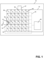
- FIG. 1 a schematic representation of an embodiment of a laboratory system (13) comprising a laboratory transport system (12) is shown.
- the laboratory transport system (12) comprises a transport plane (16), a monitoring system (18), and a control unit (20).
- the transport plane (16) has a quadratic form and comprises 36 transport positions A1 to F6 (38) arranged in a right-angled grid.
- the transport plane (16) may have any geometric form and may comprise more or less transport positions.
- a carrier identification unit (36) is connected at the transport position D1, which is a starting position (30).
- An analytical station (37) is connected at the transport position A4, which is a destination position (32).
- the laboratory transport system (12), the carrier identification unit (36), and the analytical station (37) form the laboratory system (13).
- a carrier (10) which is associated with an identity (14) is located on the starting position D1 (30).
- a non-straight transportation route (31) of the carrier (10) from the starting position D1 (30) to the destination position A4 (32) is shown in Figure 2 .
- the monitoring system (18) comprises 36 sensors (40) located at each of the 36 transport positions A1 to F6 (38).
- the sensors (40) are configured to sense the carrier (10) when the carrier (10) is located on or at one of the plurality of transport positions A1 to F6 (38).
- the control unit (20) is communicatively connected to the monitoring system (16). In the shown embodiment, the control unit (20) is also communicatively connected to the carrier identification unit (36).
- the carrier (10) moves along the seven successive transport positions D1, D2, D3, D4, C4, B4, and A4 in order to move from the starting position (30) to the destination position (32), wherein at transport position D4 the carrier (10) turns left at a right angle.
- the monitoring system (not shown) monitors motion positions (39) of the carrier (10) on the transport plane (16).
- Figure 2B shows the corresponding log data (22) when the carrier (10) which is associated with an identity ABC123 (14) moved from the starting position (30) to the destination position (32) according to the transportation route (31) as described in Figure 2A .
- the shown log data (22) of the carrier (10) which is associated with the identity ABC123 (14) represents spatio-temporal information of the carrier (10) and the identity (14) on the transport plane (16) as the identity (14) is associated with the carrier (10).
- the log data (22) of the carrier (10) associated with the identity ABC123 (14) comprises motion positions (39) for each time point (41) the carrier (10) was sensed at a transport position of the transportation route (31).
- the carrier (10) associated with the identity ABC123 (14) was sensed at transport position D1, which is the first motion position (39) of the carrier (10).
- transport position D2 which is the second motion position (39) of the carrier (10) and so on.
- Figures 3A-B show an example of how the carrier (10) moves on the transport plane (16) before and after a system failure (23) and corresponding log data (22) of the carrier (10).
- Figures 3C-E show an embodiment of how the carrier (10) can be re-identified after the system failure (23).
- Figure 3A shows the same transport plane (16) and 36 transport positions A1 to F6 (38) as shown in Figure 2 .
- the transportation route (31) as shown in Figure 2 is indicated by a dotted arrow in Figure 3A .
- the carrier (10) moves from the starting position D1 (30) to the transport position D4 when the laboratory transport system is activated.
- the carrier (10) may move by applying magnetic forces to the carrier (10).
- time point TP 4 (41) when the carrier (10) is located at transport position D4 a system failure (23) occurred. Based on the system failure (23) no magnetic forces are applied anymore to the carrier (10) and no motion positions are monitored by the monitoring system (18).
- FIG 3A instead of turning left at a right angle at transport position D4 and moving along the predefined transportation route (31), the carrier keeps moving straight forward on the transport plane (16) and moves to transport position D6 as indicated by a dashed arrow.
- Figure 3B shows the corresponding log data (22) of the carrier (10) which is associated with an identity ABC 123 (14) before and after the system failure (23) which occurred between time point TP 4 (41) and time point TP 5 (41) as indicated by an arrow at the left side of the log data (22).
- the carrier (10) associated with the identity ABC123 (14) was sensed at transport position D3 (38), which is the third motion position (39) of the carrier (10).
- transport position D4 (38) the carrier (10) associated with the identity ABC123 (14) was sensed at transport position D4 (38), which is the fourth motion position (39) of the carrier (10). Due to the system failure (23) no further motion positions are monitored at later time points.
- the associated identity (14) was localized on transport position D4 (38).
- the carrier (10) carrier kept moving straight forward to transport position D6 after time point TP 4 and no further motion positions were monitored, the associated identity (14) dissociated from the carrier (10) as indicated by asterisks in the log data (22).
- a vector (28) based on the log data (22) is determined by the control unit (20). For example, the last two monitored motion positions D3 and D4 (39) and corresponding time points TP 3 and TP 4 (41) were used to determine a motion direction as depicted by the orientation of the shown vector (28) and a motion velocity as depicted by the length of the shown vector (38). As indicated by a dotted arrow in Figure 3C , the determined vector (28) was used to simulate motion positions D5 and D6 (39) of the carrier (10) in order to predict the position of the identity ABC123 (14). The predicted position (24) of the identity ABC123 (14) is transport position D6 as shown in Figure 3C and 3E .
- Figure 3D shows the same transport plane (16) and transport positions A1 to F6 (38) as shown in Figure 3C .
- the actual position (26) of the carrier (10) is detected by the monitoring system (18) after reactivation (25) of the laboratory transport system (12) as shown in Figure 3D and 3E .
- the carrier (10) was detected on transport position D6 at time point TP 6 (41).
- the control unit (20) assigns the identity ABC123 (14) to the carrier (10).
- the carrier (10) is again associated with an identity ABC 123 (14) and the log data (22) of the carrier (10) associated with the identity ABC123 (14) comprises now a motion position (39) for time point TP 7 as shown in Figure 3E .
- Figure 4A shows an example of how a carrier (10) and a further carrier (11) move on the transport plane (16) before a system failure
- Figure 4B shows an example of how a carrier (10) and a further carrier (11) move on the transport plane (16) after a system failure
- Figures 4A-B show the same transport plane (16) and transport positions A1 to F6 (38) as shown in Figure 1 .
- a transportation route (31) of the carrier (10) associated with an identity (14) is indicated by a dotted arrow.
- the carrier (10) moves from a starting position D1 (30) to the transport position D3 (38) when the laboratory transport system is activated.
- the carrier (10) may move by applying magnetic forces to the carrier (10).
- a further carrier (11) associated with a further identity (15) is moving on the transport plane (16).
- a further transportation route (33) of the further carrier (11) is indicated by a dotted arrow.
- the further carrier (11) moves from a further starting position A4 (29) to the transport position C4 when the laboratory transport system is activated.
- the further carrier (11) may move by applying magnetic forces to the further carrier (11).
- the carrier (10) and the further carrier (11) have equal velocities, carrier features, sample tube features, and test sample features.
- both carrier possess equal motion behaviors on the transport plane (16).
- a vector (28) and a further vector (27) based on the log data of the carrier (10) and further carrier (11) are determined by the control unit (20).
- the determined vectors (27, 28) are used to simulate motion positions of the carrier (10) and the further carrier (11) in order to predict a position F4 (24) of the identity (14) and a position D6 (21) of the further identity (15).
- a collision algorithm is used for simulating the motion positions of the carrier (10) and further carrier (11) .
- the actual position F4 (26) of the carrier (10) and the actual position D6 (35) of the further carrier (11) are detected by the monitoring system (18).
- the control unit (20) assigns the identity (14) to the carrier (10).
- the control unit (20) may also assign the identity (14) to the carrier (10) if the actual position of the carrier (10) lies within a predefined perimeter (34) of the predicted position F4 (24) of the identity (14).
- the control unit (20) assigns the further identity (15) to the further carrier (11).
- the control unit (20) may also assign the further identity (15) to the further carrier (11) if the actual position of the further carrier (11) lies within a further predefined perimeter (19) of the predicted position D6 (21) of the further identity (15).
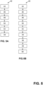
- Figures 5A-B show flowcharts of embodiments of the method (42) to re-identify a carrier (10) on a laboratory transport system (12).
- the carrier (10) is associated with an identity (14) and is configured to move over a transport plane (16) of the laboratory transport system (12).
- the laboratory transport system (12) comprises a monitoring system (18) configured to monitor motion positions (39) of the carrier (10) on the transport plane (16) when the laboratory transport system (12) is activated.
- the laboratory transport system (12) comprises a control unit (20).
- Figure 5A shows a first embodiment of the method (42) where in step a) (44) of the method (42), the monitoring system (18) monitors motion positions (39) of the carrier (10) on the transport plane (16).
- control unit (20) generates log data (22) of the carrier (10) and the associated identity (14) based on the monitored motion positions (39) in step b) (46) of the method (42).
- control unit (20) predicts the position (24) of the identity (14) based on the generated log data (22) in step c) (48) of the method (42) as the system failure (23) caused a dissociation of the identity (14) from the carrier (10).
- the monitoring system (18) detects the actual position (26) of the carrier (10) after reactivation of the laboratory transport system (12).
- Step c) (48) and step d) (50) of the method (42) may be executed simultaneously. Subsequently, the control unit (20) compares the predicted position (24) of the identity (14) with the actual position (26) of the carrier (10) in step e) (52) of the method (42). In step f) (54) of the method (42), the control unit (20) assigns the identity (14) to the carrier (10) if the predicted position (24) of the identity (14) matches with the actual position (26) of the carrier (10) in order to re-identify the carrier (10) on the laboratory transport system (12).
- Figure 5B shows a second embodiment of the method (42) if the predicted position (24) of the identity (14) does not match with the actual position (26) of the carrier (10) and the laboratory transport system (12) is connected to a carrier identification unit (36).
- Steps a) to f) (44, 46, 48, 50, 52, 54) of the second embodiment of the method (42) are the same steps a) to f) (44, 46, 48, 50, 52, 54) as described above for the first embodiment.
Landscapes
- Analytical Chemistry (AREA)
- Immunology (AREA)
- Physics & Mathematics (AREA)
- Health & Medical Sciences (AREA)
- Life Sciences & Earth Sciences (AREA)
- Chemical & Material Sciences (AREA)
- General Health & Medical Sciences (AREA)
- Biochemistry (AREA)
- Pathology (AREA)
- General Physics & Mathematics (AREA)
- Engineering & Computer Science (AREA)
- Quality & Reliability (AREA)
- Automatic Analysis And Handling Materials Therefor (AREA)
- Control Of Position, Course, Altitude, Or Attitude Of Moving Bodies (AREA)
Claims (16)
- Procédé (42) pour réidentifier un transporteur (10) sur un système de transport de laboratoire (12), dans lequel le transporteur (10) est associé à une identité (14), l'identité (14) étant un identifiant pour une identification distincte du transporteur (10) et/ou de sa charge utile, dans lequel le transporteur (10) est configuré pour se déplacer sur un plan de transport (16) du système de transport de laboratoire (12), dans lequel le système de transport de laboratoire (12) comprend un système de surveillance (18) configuré pour surveiller les positions de mouvement (39) du transporteur (10) sur le plan de transport (16) lorsque le système de transport de laboratoire (12) est activé, dans lequel le système de transport de laboratoire (12) comprend une unité de commande (20), dans lequel le procédé comprend les étapes (44, 46, 48, 50, 52, 54) suivantes :a) surveillance, par le système de surveillance (18), des positions de mouvement (39) du transporteur (10) sur le plan de transport (16)b) génération, par l'unité de commande (20), de données de journal (22) du transporteur (10) et de l'identité (14) associée sur la base des positions de mouvement (39) surveilléesc) prédiction, par l'unité de commande (20), de la position (24) de l'identité (14) sur la base des données de journal (22) générées après une défaillance de système (23) du système de transport de laboratoire (12), dans lequel la défaillance de système (23) provoque la dissociation de l'identité (14) du transporteur (10), dans lequel après la défaillance de système (23) le transporteur (10) continue à se déplacer sur le plan de transport (16)d) détection, par le système de surveillance (18), de la position (26) réelle du transporteur (10) après la réactivation du système de transport de laboratoire (12)e) comparaison, par l'unité de commande (20), de la position (24) prédite de l'identité (14) avec la position (26) réelle du transporteur (10)f) attribution, par l'unité de commande (20), de l'identité (14) au transporteur (10) si la position (24) prédite de l'identité (14) correspond à la position (26) réelle du transporteur (10).
- Procédé (42) selon la revendication 1, dans lequel la prédiction de la position (24) de l'identité (14) comprend les sous-étapes suivantes :i) détermination, par l'unité de commande (20), d'un vecteur (28) sur la base des données de journal (22), dans lequel le vecteur (28) comprend une direction de mouvement du transporteur (10) au moment de la défaillance de système (23)ii) simulation, par l'unité de commande (20), des positions de mouvement (39) du transporteur (10) sur la base du vecteur (28) déterminéiii) prédiction, par l'unité de commande (20), de la position (24) de l'identité (14) sur la base des positions de mouvement (39) simulées du transporteur (10).
- Procédé (42) selon la revendication 2, dans lequel le vecteur (28) comprend en outre une vitesse de mouvement du transporteur (10) au moment de la défaillance de système (23).
- Procédé (42) selon l'une quelconque des revendications 2 à 3, dans lequel la simulation des positions de mouvement (39) du transporteur (10) utilise une règle de transport prédéfinie sur le plan de transport (16) du système de transport de laboratoire (12).
- Procédé (42) selon l'une quelconque des revendications 2 à 4, dans lequel la simulation des positions de mouvement (39) du transporteur (10) utilise un algorithme de collision simulant une ou plusieurs collisions du transporteur (10) avec un ou plusieurs autres transporteurs et/ou un ou plusieurs bords du plan de transport (16).
- Procédé (42) selon l'une quelconque des revendications 2 à 5, dans lequel la simulation des positions de mouvement (39) du transporteur (10) utilise des voies de transport prédéfinies, dans lequel chaque voie de transport définit un trajet ou une partie du trajet du transporteur (10) se déplace d'une position de départ (30) définie vers une position de destination (32) définie sur le plan de transport (16) du système de transport de laboratoire (12).
- Procédé (42) selon l'une quelconque des revendications 2 à 6, dans lequel la simulation des positions de mouvement (39) du transporteur (10) utilise une ou plusieurs des caractéristiques suivantes :- une caractéristique du transporteur- une caractéristique du plan de transport- une caractéristique du tube à échantillon- une caractéristique de l'échantillon de test.
- Procédé (42) selon l'une quelconque des revendications 1 à 7, dans lequel la position (24) prédite de l'identité (14) correspond à la position (26) réelle du transporteur (10) si la position (26) réelle du transporteur (10) se situe à l'intérieur d'un périmètre (34) prédéfini de la position (24) prédite de l'identité (14) ou si la position (24) prédite de l'identité (14) se situe à l'intérieur d'un périmètre prédéfini de la position (26) réelle du transporteur (10).
- Procédé (42) selon la revendication 1, dans lequel le système de transport de laboratoire (12) est connecté à une unité d'identification de transporteur (36), dans lequel le procédé comprend en outre les étapes (56, 58, 60) suivantes :g) transport, par le système de transport de laboratoire (12), du transporteur (10) vers une unité d'identification de transporteur (36) si la position (24) prédite de l'identité (14) ne correspond pas à la position (26) réelle du transporteur (10)h) détermination, par l'unité d'identification de transporteur (36), de l'identité (14) du transporteur (10)i) attribution, par l'unité de commande (20), de l'identité (14) déterminée au transporteur (10).
- Procédé (42) selon l'une quelconque des revendications 1 à 9, dans lequel le système de transport de laboratoire (12) comprend un certain nombre d'actionneurs électromagnétiques disposés de manière stationnaire sous le plan de transport (16) et conçus pour générer des champs magnétiques pour déplacer le transporteur (10), dans lequel chaque transporteur (10) comprend un dispositif magnétiquement actif qui peut interagir avec les champs magnétiques de sorte qu'une force magnétique est appliquée sur le transporteur (10) pour déplacer le transporteur (10) sur le plan de transport (16).
- Procédé (42) selon l'une quelconque des revendications 1 à 10, dans lequel le plan de transport (16) comprend une pluralité de positions de transport (38), dans lequel le système de surveillance (18) comprend un capteur (40) au niveau de chaque position de transport (38) pour détecter le transporteur (10) lorsque le transporteur (10) est situé sur ou au niveau de l'une parmi la pluralité de positions de transport (38), dans lequel à l'étape b) les données de journal (22) du transporteur (10) et de l'identité (14) associée sont générées sur la base de points temporels (41) lorsque le transporteur (10) est détecté par les capteurs (40) sur ou au niveau de la pluralité de positions de transport (38).
- Procédé (42) selon la revendication 11, dans lequel les capteurs (40) sont des capteurs électromagnétiques compris par le plan de transport.
- Système de transport de laboratoire (12), dans lequel le système de transport de laboratoire (12) comprend un transporteur (10), un plan de transport (16) comprenant une pluralité de positions de transport,un système de surveillance (18) comprenant un capteur au niveau de chaque position de transport, dans lequel le système de surveillance est configuré pour détecter le transporteur lorsque le transporteur est situé sur ou au niveau de l'une parmi la pluralité de positions de transport,et une unité de commande (20) connectée en communication avec le système de surveillance,dans lequel le transporteur (10) est associé à une identité (14), l'identité (14) étant un identifiant pour une identification distincte du transporteur (10) et/ou de sa charge utile, dans lequel le transporteur (10) est configuré pour se déplacer sur le plan de transport (16),dans lequel le système de transport de laboratoire (12) est configuré pour réidentifier le transporteur sur le système de transport de laboratoire en exécutant les étapes du procédé selon l'une quelconque des revendications 1 à 8.
- Système de transport de laboratoire (12) selon la revendication 13, dans lequel le système de transport de laboratoire (12) est connecté à une unité d'identification de transporteur (36), dans lequel le système de transport de laboratoire (12) est configuré pour exécuter les étapes du procédé selon l'une quelconque des revendications 1 à 12.
- Produit de programme informatique comprenant des instructions pour amener le système de transport de laboratoire (12) selon la revendication 13 à exécuter les étapes du procédé selon l'une quelconque des revendications 1 à 8.
- Support de stockage lisible par ordinateur sur lequel est stocké le produit de programme informatique selon la revendication 15.
Priority Applications (4)
| Application Number | Priority Date | Filing Date | Title |
|---|---|---|---|
| EP20165745.9A EP3885771B1 (fr) | 2020-03-26 | 2020-03-26 | Procédé et système pour réidentifier des transporteurs sur un système de transport de laboratoire |
| JP2021048106A JP7708562B2 (ja) | 2020-03-26 | 2021-03-23 | 実験室輸送システムにおいてキャリアを再識別する方法およびシステム |
| US17/211,113 US11747354B2 (en) | 2020-03-26 | 2021-03-24 | Method and system to re-identify carriers on a laboratory transport system |
| CN202110322761.9A CN113447667A (zh) | 2020-03-26 | 2021-03-25 | 在实验室运送系统上重新识别载具的方法和系统 |
Applications Claiming Priority (1)
| Application Number | Priority Date | Filing Date | Title |
|---|---|---|---|
| EP20165745.9A EP3885771B1 (fr) | 2020-03-26 | 2020-03-26 | Procédé et système pour réidentifier des transporteurs sur un système de transport de laboratoire |
Publications (2)
| Publication Number | Publication Date |
|---|---|
| EP3885771A1 EP3885771A1 (fr) | 2021-09-29 |
| EP3885771B1 true EP3885771B1 (fr) | 2024-11-27 |
Family
ID=70008407
Family Applications (1)
| Application Number | Title | Priority Date | Filing Date |
|---|---|---|---|
| EP20165745.9A Active EP3885771B1 (fr) | 2020-03-26 | 2020-03-26 | Procédé et système pour réidentifier des transporteurs sur un système de transport de laboratoire |
Country Status (4)
| Country | Link |
|---|---|
| US (1) | US11747354B2 (fr) |
| EP (1) | EP3885771B1 (fr) |
| JP (1) | JP7708562B2 (fr) |
| CN (1) | CN113447667A (fr) |
Families Citing this family (1)
| Publication number | Priority date | Publication date | Assignee | Title |
|---|---|---|---|---|
| CN116660566B (zh) * | 2023-07-26 | 2023-10-17 | 四川徕伯益自动化技术有限公司 | 一种样本液的位置识别方法、系统、终端及介质 |
Family Cites Families (14)
| Publication number | Priority date | Publication date | Assignee | Title |
|---|---|---|---|---|
| US8838374B2 (en) | 2005-07-05 | 2014-09-16 | Mi-Jack Products, Inc. | Automatic correction of past position errors for location and inventory tracking |
| US7746228B2 (en) | 2006-06-12 | 2010-06-29 | Sensenig Tim R | Passive container tracking device, system, and method |
| EP2080553A1 (fr) | 2008-01-18 | 2009-07-22 | F. Hoffmann-Roche AG | Procédé et système pour localiser et identifier au moins un tube de test parmi plusieurs |
| DE102010028769A1 (de) | 2010-05-07 | 2011-11-10 | Pvt Probenverteiltechnik Gmbh | System zum Transportieren von Behältern zwischen unterschiedlichen Stationen und Behälterträger |
| US9632102B2 (en) * | 2011-09-25 | 2017-04-25 | Theranos, Inc. | Systems and methods for multi-purpose analysis |
| EP2589966A1 (fr) * | 2011-11-04 | 2013-05-08 | Roche Diagnostics GmbH | Système de distribution d'échantillon de laboratoire et procédé correspondant de fonctionnement |
| US9894746B2 (en) * | 2012-03-30 | 2018-02-13 | General Electric Company | Target windows for isotope systems |
| JP6177895B2 (ja) * | 2012-05-24 | 2017-08-09 | シーメンス・ヘルスケア・ダイアグノスティックス・インコーポレーテッドSiemens Healthcare Diagnostics Inc. | 知能オートメーションパック用非接触光エンコーディングスキーム |
| EP2957914B1 (fr) * | 2014-06-17 | 2018-01-03 | Roche Diagnostics GmbH | Système de distribution d'échantillons de laboratoire et système d'automatisation de laboratoire |
| EP2988134A1 (fr) | 2014-08-21 | 2016-02-24 | Roche Diagniostics GmbH | Support de récipient d'échantillon pour un système de distribution d'échantillons de laboratoire, ledit système de distribution et système d'automatisation de laboratoire |
| EP3070479B1 (fr) | 2015-03-16 | 2019-07-03 | Roche Diagniostics GmbH | Support de transport, système de distribution de marchandises de laboratoire et système d'automatisation de laboratoire |
| CN109791160B (zh) | 2016-06-27 | 2023-10-24 | 贝克曼考尔特公司 | 生物材料样本的历史记录 |
| US10977605B2 (en) * | 2018-06-05 | 2021-04-13 | Signal Ocean Ltd | Carrier path prediction based on dynamic input data |
| CN211826092U (zh) * | 2018-09-11 | 2020-10-30 | 贝克顿·迪金森公司 | 具有自动化位置获悉的用于诊断测试的机器人样品制备系统 |
-
2020
- 2020-03-26 EP EP20165745.9A patent/EP3885771B1/fr active Active
-
2021
- 2021-03-23 JP JP2021048106A patent/JP7708562B2/ja active Active
- 2021-03-24 US US17/211,113 patent/US11747354B2/en active Active
- 2021-03-25 CN CN202110322761.9A patent/CN113447667A/zh active Pending
Also Published As
| Publication number | Publication date |
|---|---|
| US20210302449A1 (en) | 2021-09-30 |
| JP7708562B2 (ja) | 2025-07-15 |
| US11747354B2 (en) | 2023-09-05 |
| EP3885771A1 (fr) | 2021-09-29 |
| JP2021156886A (ja) | 2021-10-07 |
| CN113447667A (zh) | 2021-09-28 |
Similar Documents
| Publication | Publication Date | Title |
|---|---|---|
| US10352953B2 (en) | Method of operating a laboratory sample distribution system, laboratory sample distribution system and a laboratory automation system | |
| US20140344118A1 (en) | Automated Inventory Management | |
| EP3488240B1 (fr) | Système et procédé de surveillance et de maintenance à base de condition d'une piste d'automatisation | |
| JP7442281B2 (ja) | 生物試料を分析するための検査室システム | |
| US11579156B2 (en) | Method and laboratory system to provide control samples for validating a diagnostic test | |
| EP3373211A1 (fr) | Dispositif de gestion et support non transitoire lisible par ordinateur | |
| JP7433818B2 (ja) | 実験室用消耗品管理システム | |
| CN101167082A (zh) | Rfid标签灵敏度 | |
| CN116415866B (zh) | 一种物流运输装置、控制方法、系统及介质 | |
| CN109848070B (zh) | 一种产品分拣系统及方法 | |
| CN109478350B (zh) | 确定维护关注的航空器数据记录帧配置的系统和方法 | |
| EP3885771B1 (fr) | Procédé et système pour réidentifier des transporteurs sur un système de transport de laboratoire | |
| CN117302829A (zh) | 一种自动化的医疗器械仓储控制系统 | |
| Özgür et al. | Comparing sensor-based and camera-based approaches to recognizing the occupancy status of the load handling device of forklift trucks | |
| US12242254B2 (en) | Production systems and production control methods with locating system-based simulations of production sequences | |
| WO2007061837A1 (fr) | Determination d'un etat pour un objet identifie par une etiquette d'identification par radio-frequence | |
| CN117808405B (zh) | 一种基于物联网技术的rfid盘点方法、装置和存储介质 | |
| US11922256B2 (en) | Industrial device and method of reading a tag located on an object using a model | |
| CN113487255B (zh) | 一种样品流转管控方法及电子设备 | |
| JP2021043195A (ja) | 実験室輸送システム上においてキャリアを位置特定する方法およびシステム | |
| CN120181536B (zh) | 一种12轴pcb钻孔机agv物料流转调度系统 | |
| CN111209762A (zh) | 信息识别装置、系统及识别方法 | |
| WO2025174543A1 (fr) | Dispositifs et procédés de transport de porte-échantillons dans des systèmes de laboratoire de diagnostic | |
| CN120500669A (zh) | 故障的处理方法、设备、存储介质及程序产品 | |
| CN113847910A (zh) | 生成方法、监测方法、装置、电子设备以及可读介质 |
Legal Events
| Date | Code | Title | Description |
|---|---|---|---|
| PUAI | Public reference made under article 153(3) epc to a published international application that has entered the european phase |
Free format text: ORIGINAL CODE: 0009012 |
|
| STAA | Information on the status of an ep patent application or granted ep patent |
Free format text: STATUS: THE APPLICATION HAS BEEN PUBLISHED |
|
| AK | Designated contracting states |
Kind code of ref document: A1 Designated state(s): AL AT BE BG CH CY CZ DE DK EE ES FI FR GB GR HR HU IE IS IT LI LT LU LV MC MK MT NL NO PL PT RO RS SE SI SK SM TR |
|
| STAA | Information on the status of an ep patent application or granted ep patent |
Free format text: STATUS: REQUEST FOR EXAMINATION WAS MADE |
|
| 17P | Request for examination filed |
Effective date: 20220329 |
|
| RBV | Designated contracting states (corrected) |
Designated state(s): AL AT BE BG CH CY CZ DE DK EE ES FI FR GB GR HR HU IE IS IT LI LT LU LV MC MK MT NL NO PL PT RO RS SE SI SK SM TR |
|
| STAA | Information on the status of an ep patent application or granted ep patent |
Free format text: STATUS: EXAMINATION IS IN PROGRESS |
|
| 17Q | First examination report despatched |
Effective date: 20230721 |
|
| GRAP | Despatch of communication of intention to grant a patent |
Free format text: ORIGINAL CODE: EPIDOSNIGR1 |
|
| STAA | Information on the status of an ep patent application or granted ep patent |
Free format text: STATUS: GRANT OF PATENT IS INTENDED |
|
| INTG | Intention to grant announced |
Effective date: 20240712 |
|
| GRAS | Grant fee paid |
Free format text: ORIGINAL CODE: EPIDOSNIGR3 |
|
| GRAA | (expected) grant |
Free format text: ORIGINAL CODE: 0009210 |
|
| STAA | Information on the status of an ep patent application or granted ep patent |
Free format text: STATUS: THE PATENT HAS BEEN GRANTED |
|
| AK | Designated contracting states |
Kind code of ref document: B1 Designated state(s): AL AT BE BG CH CY CZ DE DK EE ES FI FR GB GR HR HU IE IS IT LI LT LU LV MC MK MT NL NO PL PT RO RS SE SI SK SM TR |
|
| REG | Reference to a national code |
Ref country code: GB Ref legal event code: FG4D |
|
| REG | Reference to a national code |
Ref country code: CH Ref legal event code: EP |
|
| REG | Reference to a national code |
Ref country code: DE Ref legal event code: R096 Ref document number: 602020041923 Country of ref document: DE |
|
| REG | Reference to a national code |
Ref country code: IE Ref legal event code: FG4D |
|
| REG | Reference to a national code |
Ref country code: LT Ref legal event code: MG9D |
|
| REG | Reference to a national code |
Ref country code: NL Ref legal event code: MP Effective date: 20241127 |
|
| PG25 | Lapsed in a contracting state [announced via postgrant information from national office to epo] |
Ref country code: IS Free format text: LAPSE BECAUSE OF FAILURE TO SUBMIT A TRANSLATION OF THE DESCRIPTION OR TO PAY THE FEE WITHIN THE PRESCRIBED TIME-LIMIT Effective date: 20250327 Ref country code: HR Free format text: LAPSE BECAUSE OF FAILURE TO SUBMIT A TRANSLATION OF THE DESCRIPTION OR TO PAY THE FEE WITHIN THE PRESCRIBED TIME-LIMIT Effective date: 20241127 Ref country code: PT Free format text: LAPSE BECAUSE OF FAILURE TO SUBMIT A TRANSLATION OF THE DESCRIPTION OR TO PAY THE FEE WITHIN THE PRESCRIBED TIME-LIMIT Effective date: 20250327 |
|
| PG25 | Lapsed in a contracting state [announced via postgrant information from national office to epo] |
Ref country code: FI Free format text: LAPSE BECAUSE OF FAILURE TO SUBMIT A TRANSLATION OF THE DESCRIPTION OR TO PAY THE FEE WITHIN THE PRESCRIBED TIME-LIMIT Effective date: 20241127 Ref country code: NL Free format text: LAPSE BECAUSE OF FAILURE TO SUBMIT A TRANSLATION OF THE DESCRIPTION OR TO PAY THE FEE WITHIN THE PRESCRIBED TIME-LIMIT Effective date: 20241127 |
|
| REG | Reference to a national code |
Ref country code: AT Ref legal event code: MK05 Ref document number: 1746142 Country of ref document: AT Kind code of ref document: T Effective date: 20241127 |
|
| PG25 | Lapsed in a contracting state [announced via postgrant information from national office to epo] |
Ref country code: BG Free format text: LAPSE BECAUSE OF FAILURE TO SUBMIT A TRANSLATION OF THE DESCRIPTION OR TO PAY THE FEE WITHIN THE PRESCRIBED TIME-LIMIT Effective date: 20241127 |
|
| PG25 | Lapsed in a contracting state [announced via postgrant information from national office to epo] |
Ref country code: ES Free format text: LAPSE BECAUSE OF FAILURE TO SUBMIT A TRANSLATION OF THE DESCRIPTION OR TO PAY THE FEE WITHIN THE PRESCRIBED TIME-LIMIT Effective date: 20241127 |
|
| PG25 | Lapsed in a contracting state [announced via postgrant information from national office to epo] |
Ref country code: NO Free format text: LAPSE BECAUSE OF FAILURE TO SUBMIT A TRANSLATION OF THE DESCRIPTION OR TO PAY THE FEE WITHIN THE PRESCRIBED TIME-LIMIT Effective date: 20250227 |
|
| PG25 | Lapsed in a contracting state [announced via postgrant information from national office to epo] |
Ref country code: LV Free format text: LAPSE BECAUSE OF FAILURE TO SUBMIT A TRANSLATION OF THE DESCRIPTION OR TO PAY THE FEE WITHIN THE PRESCRIBED TIME-LIMIT Effective date: 20241127 Ref country code: GR Free format text: LAPSE BECAUSE OF FAILURE TO SUBMIT A TRANSLATION OF THE DESCRIPTION OR TO PAY THE FEE WITHIN THE PRESCRIBED TIME-LIMIT Effective date: 20250228 Ref country code: AT Free format text: LAPSE BECAUSE OF FAILURE TO SUBMIT A TRANSLATION OF THE DESCRIPTION OR TO PAY THE FEE WITHIN THE PRESCRIBED TIME-LIMIT Effective date: 20241127 |
|
| PG25 | Lapsed in a contracting state [announced via postgrant information from national office to epo] |
Ref country code: PL Free format text: LAPSE BECAUSE OF FAILURE TO SUBMIT A TRANSLATION OF THE DESCRIPTION OR TO PAY THE FEE WITHIN THE PRESCRIBED TIME-LIMIT Effective date: 20241127 |
|
| PG25 | Lapsed in a contracting state [announced via postgrant information from national office to epo] |
Ref country code: RS Free format text: LAPSE BECAUSE OF FAILURE TO SUBMIT A TRANSLATION OF THE DESCRIPTION OR TO PAY THE FEE WITHIN THE PRESCRIBED TIME-LIMIT Effective date: 20250227 |
|
| PG25 | Lapsed in a contracting state [announced via postgrant information from national office to epo] |
Ref country code: SM Free format text: LAPSE BECAUSE OF FAILURE TO SUBMIT A TRANSLATION OF THE DESCRIPTION OR TO PAY THE FEE WITHIN THE PRESCRIBED TIME-LIMIT Effective date: 20241127 |
|
| PG25 | Lapsed in a contracting state [announced via postgrant information from national office to epo] |
Ref country code: DK Free format text: LAPSE BECAUSE OF FAILURE TO SUBMIT A TRANSLATION OF THE DESCRIPTION OR TO PAY THE FEE WITHIN THE PRESCRIBED TIME-LIMIT Effective date: 20241127 |
|
| PG25 | Lapsed in a contracting state [announced via postgrant information from national office to epo] |
Ref country code: EE Free format text: LAPSE BECAUSE OF FAILURE TO SUBMIT A TRANSLATION OF THE DESCRIPTION OR TO PAY THE FEE WITHIN THE PRESCRIBED TIME-LIMIT Effective date: 20241127 |
|
| PG25 | Lapsed in a contracting state [announced via postgrant information from national office to epo] |
Ref country code: RO Free format text: LAPSE BECAUSE OF FAILURE TO SUBMIT A TRANSLATION OF THE DESCRIPTION OR TO PAY THE FEE WITHIN THE PRESCRIBED TIME-LIMIT Effective date: 20241127 |
|
| PG25 | Lapsed in a contracting state [announced via postgrant information from national office to epo] |
Ref country code: SK Free format text: LAPSE BECAUSE OF FAILURE TO SUBMIT A TRANSLATION OF THE DESCRIPTION OR TO PAY THE FEE WITHIN THE PRESCRIBED TIME-LIMIT Effective date: 20241127 |
|
| PG25 | Lapsed in a contracting state [announced via postgrant information from national office to epo] |
Ref country code: CZ Free format text: LAPSE BECAUSE OF FAILURE TO SUBMIT A TRANSLATION OF THE DESCRIPTION OR TO PAY THE FEE WITHIN THE PRESCRIBED TIME-LIMIT Effective date: 20241127 |
|
| PG25 | Lapsed in a contracting state [announced via postgrant information from national office to epo] |
Ref country code: IT Free format text: LAPSE BECAUSE OF FAILURE TO SUBMIT A TRANSLATION OF THE DESCRIPTION OR TO PAY THE FEE WITHIN THE PRESCRIBED TIME-LIMIT Effective date: 20241127 |
|
| REG | Reference to a national code |
Ref country code: DE Ref legal event code: R097 Ref document number: 602020041923 Country of ref document: DE |
|
| PG25 | Lapsed in a contracting state [announced via postgrant information from national office to epo] |
Ref country code: SE Free format text: LAPSE BECAUSE OF FAILURE TO SUBMIT A TRANSLATION OF THE DESCRIPTION OR TO PAY THE FEE WITHIN THE PRESCRIBED TIME-LIMIT Effective date: 20241127 |
|
| PLBE | No opposition filed within time limit |
Free format text: ORIGINAL CODE: 0009261 |
|
| STAA | Information on the status of an ep patent application or granted ep patent |
Free format text: STATUS: NO OPPOSITION FILED WITHIN TIME LIMIT |
|
| REG | Reference to a national code |
Ref country code: CH Ref legal event code: L10 Free format text: ST27 STATUS EVENT CODE: U-0-0-L10-L00 (AS PROVIDED BY THE NATIONAL OFFICE) Effective date: 20251008 |
|
| PG25 | Lapsed in a contracting state [announced via postgrant information from national office to epo] |
Ref country code: MC Free format text: LAPSE BECAUSE OF FAILURE TO SUBMIT A TRANSLATION OF THE DESCRIPTION OR TO PAY THE FEE WITHIN THE PRESCRIBED TIME-LIMIT Effective date: 20241127 |
|
| REG | Reference to a national code |
Ref country code: CH Ref legal event code: H13 Free format text: ST27 STATUS EVENT CODE: U-0-0-H10-H13 (AS PROVIDED BY THE NATIONAL OFFICE) Effective date: 20251023 |
|
| 26N | No opposition filed |
Effective date: 20250828 |
|
| PG25 | Lapsed in a contracting state [announced via postgrant information from national office to epo] |
Ref country code: LU Free format text: LAPSE BECAUSE OF NON-PAYMENT OF DUE FEES Effective date: 20250326 |
|
| REG | Reference to a national code |
Ref country code: BE Ref legal event code: MM Effective date: 20250331 |
|
| PG25 | Lapsed in a contracting state [announced via postgrant information from national office to epo] |
Ref country code: BE Free format text: LAPSE BECAUSE OF NON-PAYMENT OF DUE FEES Effective date: 20250331 |
|
| PG25 | Lapsed in a contracting state [announced via postgrant information from national office to epo] |
Ref country code: CH Free format text: LAPSE BECAUSE OF NON-PAYMENT OF DUE FEES Effective date: 20250331 |
|
| PG25 | Lapsed in a contracting state [announced via postgrant information from national office to epo] |
Ref country code: IE Free format text: LAPSE BECAUSE OF NON-PAYMENT OF DUE FEES Effective date: 20250326 |
|
| PGFP | Annual fee paid to national office [announced via postgrant information from national office to epo] |
Ref country code: GB Payment date: 20260219 Year of fee payment: 7 |
|
| PGFP | Annual fee paid to national office [announced via postgrant information from national office to epo] |
Ref country code: DE Payment date: 20260219 Year of fee payment: 7 |
|
| PGFP | Annual fee paid to national office [announced via postgrant information from national office to epo] |
Ref country code: FR Payment date: 20260220 Year of fee payment: 7 |