EP3886224A1 - Système de pile à combustible comprenant une pluralité de piles à combustible - Google Patents
Système de pile à combustible comprenant une pluralité de piles à combustible Download PDFInfo
- Publication number
- EP3886224A1 EP3886224A1 EP19886526.3A EP19886526A EP3886224A1 EP 3886224 A1 EP3886224 A1 EP 3886224A1 EP 19886526 A EP19886526 A EP 19886526A EP 3886224 A1 EP3886224 A1 EP 3886224A1
- Authority
- EP
- European Patent Office
- Prior art keywords
- fuel cell
- heat
- storage tank
- heat storage
- water
- Prior art date
- Legal status (The legal status is an assumption and is not a legal conclusion. Google has not performed a legal analysis and makes no representation as to the accuracy of the status listed.)
- Withdrawn
Links
Images


Classifications
-
- H—ELECTRICITY
- H01—ELECTRIC ELEMENTS
- H01M—PROCESSES OR MEANS, e.g. BATTERIES, FOR THE DIRECT CONVERSION OF CHEMICAL ENERGY INTO ELECTRICAL ENERGY
- H01M8/00—Fuel cells; Manufacture thereof
- H01M8/04—Auxiliary arrangements, e.g. for control of pressure or for circulation of fluids
- H01M8/04007—Auxiliary arrangements, e.g. for control of pressure or for circulation of fluids related to heat exchange
- H01M8/04052—Storage of heat in the fuel cell system
-
- H—ELECTRICITY
- H01—ELECTRIC ELEMENTS
- H01M—PROCESSES OR MEANS, e.g. BATTERIES, FOR THE DIRECT CONVERSION OF CHEMICAL ENERGY INTO ELECTRICAL ENERGY
- H01M8/00—Fuel cells; Manufacture thereof
- H01M8/04—Auxiliary arrangements, e.g. for control of pressure or for circulation of fluids
- H01M8/04007—Auxiliary arrangements, e.g. for control of pressure or for circulation of fluids related to heat exchange
- H01M8/04029—Heat exchange using liquids
-
- H—ELECTRICITY
- H01—ELECTRIC ELEMENTS
- H01M—PROCESSES OR MEANS, e.g. BATTERIES, FOR THE DIRECT CONVERSION OF CHEMICAL ENERGY INTO ELECTRICAL ENERGY
- H01M8/00—Fuel cells; Manufacture thereof
- H01M8/24—Grouping of fuel cells, e.g. stacking of fuel cells
- H01M8/249—Grouping of fuel cells, e.g. stacking of fuel cells comprising two or more groupings of fuel cells, e.g. modular assemblies
-
- H—ELECTRICITY
- H01—ELECTRIC ELEMENTS
- H01M—PROCESSES OR MEANS, e.g. BATTERIES, FOR THE DIRECT CONVERSION OF CHEMICAL ENERGY INTO ELECTRICAL ENERGY
- H01M2250/00—Fuel cells for particular applications; Specific features of fuel cell system
- H01M2250/40—Combination of fuel cells with other energy production systems
- H01M2250/405—Cogeneration of heat or hot water
-
- Y—GENERAL TAGGING OF NEW TECHNOLOGICAL DEVELOPMENTS; GENERAL TAGGING OF CROSS-SECTIONAL TECHNOLOGIES SPANNING OVER SEVERAL SECTIONS OF THE IPC; TECHNICAL SUBJECTS COVERED BY FORMER USPC CROSS-REFERENCE ART COLLECTIONS [XRACs] AND DIGESTS
- Y02—TECHNOLOGIES OR APPLICATIONS FOR MITIGATION OR ADAPTATION AGAINST CLIMATE CHANGE
- Y02E—REDUCTION OF GREENHOUSE GAS [GHG] EMISSIONS, RELATED TO ENERGY GENERATION, TRANSMISSION OR DISTRIBUTION
- Y02E60/00—Enabling technologies; Technologies with a potential or indirect contribution to GHG emissions mitigation
- Y02E60/30—Hydrogen technology
- Y02E60/50—Fuel cells
-
- Y—GENERAL TAGGING OF NEW TECHNOLOGICAL DEVELOPMENTS; GENERAL TAGGING OF CROSS-SECTIONAL TECHNOLOGIES SPANNING OVER SEVERAL SECTIONS OF THE IPC; TECHNICAL SUBJECTS COVERED BY FORMER USPC CROSS-REFERENCE ART COLLECTIONS [XRACs] AND DIGESTS
- Y02—TECHNOLOGIES OR APPLICATIONS FOR MITIGATION OR ADAPTATION AGAINST CLIMATE CHANGE
- Y02P—CLIMATE CHANGE MITIGATION TECHNOLOGIES IN THE PRODUCTION OR PROCESSING OF GOODS
- Y02P70/00—Climate change mitigation technologies in the production process for final industrial or consumer products
- Y02P70/50—Manufacturing or production processes characterised by the final manufactured product
Definitions
- the present invention relates to a fuel cell system having multiple fuel cells, and more particularly, to a fuel cell system capable of efficiently managing the heat generated from multiple fuel cells.
- a fuel cell inevitably generates heat during an operation process, and needs to properly cool the heat because such heat affects the operation of the fuel cell.
- a fuel cell heat exchanger using external coolant is used, and a heat storage tank which stores the heat of the coolant and utilizes it separately is used as many as the number of fuel cells.
- the heat storage tank is typically composed of a heat storage tank which stores working fluid, and heat exchange coils which are configured to be installed in the heat storage tank and in which the coolant that has cooled the fuel cell is circulated. That is, the coolant of the fuel cell circulates the inside of the heat exchange coils immersed in the working fluid stored in the heat storage tank and is cooled, and the heat transferred to the working fluid can be used as hot water for heating.
- Each of the heat exchange coils is formed as a single passage having a hot water inlet and a circulation water inlet for heat exchange on one side, and a hot water outlet and a circulation water outlet for heat exchange on the other side, and heats the hot water and circulation water for heat exchange flowing in a low temperature state and supplies them.
- a polymer electrolyte fuel cell heat exchanger has a temperature accumulated in the heat storage tank of about 60°C to 80°C, and is mainly operated at 65°C or less.
- the present invention is devised to solve the conventional problems as described above, and the object of the invention is to provide a fuel cell system capable of simplifying the overall system configuration without increasing the volume even if multiple fuel cells are included.
- a fuel cell system includes multiple fuel cells; a fuel cell heat exchanger that is provided for each of the fuel cells, and exchanges heat between coolant cooling the fuel cell and system water; a heat storage tank that stores the system water; a heat exchanger for hot water supply that supplies heat of the system water in the heat storage tank to low-temperature water introduced from an outside; and a heat exchanger for heat dissipation that is disposed between the heat storage tank and any one of the fuel cell heat exchangers.
- the heat generated in the fuel cell is supplied to the system water, and the heat supplied to the system water is selectively transferred to the low-temperature water through the heat exchanger for hot water supply or radiated to an outside through the heat exchanger for heat dissipation.
- control valve that is disposed between each of the fuel cell heat exchangers and the heat storage tank, and controls the supply of the system water to the fuel cell heat exchanger may be further included.
- the control valve may selectively supply the system water to the fuel cell heat exchanger depending on a temperature of the fuel cell.
- system water recovered from the fuel cell heat exchanger may flow into an upper portion of the heat storage tank.
- the system water may be supplied to the heat exchanger for hot water supply in preference to the heat exchanger for heat dissipation.
- system water supplied to the heat exchanger for heat dissipation may be discharged from a lower portion of the heat storage tank.
- the heat exchanger for heat dissipation may be fluidly connected to a radiator for dissipating heat into an atmosphere.
- a hot water discharge pipe for discharging the system water in the heat storage tank may be provided on an upper portion of the heat storage tank.
- a control valve may be provided in the hot water discharge pipe, and the hot water discharge pipe may be controlled to be opened if a temperature of the system water in the heat storage tank is higher than a set temperature.
- a fluid supply pipe for replenishing the system water may be provided at a lower portion of the heat storage tank.
- the low-temperature water heated by the heat exchanger for hot water supply may be supplied to a user as hot water.
- the heat exchanger for heat dissipation may be disposed immediately preceding the fuel cell heat exchanger based on a flow direction of the system water.
- a pump for circulating the system water may be further included.
- the pump may operate and circulate the system water if a temperature of the system water in the heat storage tank falls below a set minimum temperature in a state in which an operation of the fuel cell is stopped.
- multiple fuel cells can be efficiently and independently cooled using one heat storage tank. Further, the size increasing of the heat storage tank can be minimized because heat exchange coils are not disposed inside the heat storage tank.
- a heat storage tank 100 is a device for storing the waste heat generated from a fuel cell heat exchanger 200 and utilizing the stored waste heat at a time desired by a user.
- the heat storage tank 100 of the present invention does not have heat exchange coils therein, but has a configuration in which the coolant for fuel cells and the system water stored in the heat storage tank 100 are exchanged with each other in the fuel cell heat exchanger 200 disposed outside the heat storage tank 100.
- the volume increase of the heat storage tank 100 due to the internal flow path of the heat storage tank 100 in connecting to several fuel cell heat exchangers 200 can be prevented because the flow path is not installed therein.
- cost reduction can be achieved by preventing an increase in the volume of the heat storage tank 100.
- the internal structure of the heat storage tank 100 to be an empty structure, an increase in the volume of the heat storage tank 100 due to the connection of the multiple fuel cell heat exchangers 200 can be avoided because a flow path is not formed inside the heat storage tank 100.
- manufacturing cost can be reduced by manufacturing the heat storage tank 100 for connecting the multiple fuel cell heat exchangers 200 by avoiding the increase in volume.
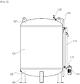
- the heat storage tank 100 is composed of an upper cap 102, a body part 104, and a lower cap 106, and may optionally include a support 108 in some cases.
- the upper cap 102 is mounted on the body part 104, and, in general, a portion to be mounted on the body part 104 may have a flat shape and a portion not to be mounted on the body part 104 may have a round shape.
- the manner of being mounted on the body part 104 may be various, and may be fused for a solid bond.
- the lower cap 106 may be generally manufactured in the same shape as the upper cap 102, and may be mounted on the body part 104 so as to be symmetrical with the upper cap 102 based on the body part 104.
- the support 108 is a device for supporting the heat storage tank 100 and is generally mounted on the lower cap 106 of the heat storage tank 100. Since the support 108 only needs to have a function for supporting the heat storage tank 100, there is no limitation on its shape and number. In one embodiment of the present invention shown in FIG. 1 , four supports 108 are coupled to the vicinity of the outer side of the upper cap 102, and the support 108 has a general beam shape. In addition, the portion of the support 108 in contact with a ground has a larger area for stable support of the heat storage tank 100.
- the support 108 does not need to be mounted, so that the heat storage tank 100 without the support 108 may be possible.
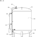
- a system water inlet pipe 110 is a path through which a fluid that has absorbed the waste heat of the fuel cell heat exchanger 200 flows into the heat storage tank 100, and a high-temperature fluid flows through the path.
- a system water outlet pipe 112 is a path through which a fluid from which waste heat has escaped discharges from the heat storage tank 100 flows out, and a low-temperature fluid flows through the path.
- the system water inlet pipe 110 and the system water outlet pipe 112 are connected to the heat storage tank 100 .
- the system water inlet pipe 110 is connected to the upper portion of the heat storage tank 100 and the system water outlet pipe 112 is connected to the lower portion of the heat storage tank 100. This takes into account the difference in density resulting from the temperature difference in which a high-temperature part is located at the upper portion and a low-temperature part is located at the lower portion.
- a system water transfer pump 114 is installed in the system water outlet pipe 112 near the heat storage tank 100 to circulate the system water discharged from the heat storage tank 100 to the fuel cell heat exchanger 200 and the heat storage tank 100.
- a system water recovery pipe 122 for hot water supply is a path through which the circulation water for heat exchange flows from a heat exchanger 300 for hot water supply to the heat storage tank 100, and a low-temperature fluid flows through the path.
- a system water supply pipe 120 for hot water is a path through which the circulation water for heat exchange, whose temperature has risen due to the waste heat stored in the heat storage tank 100, flows out of the heat storage tank 100, and a high-temperature fluid flows through the path.
- the position where the system water recovery pipe 122 for hot water supply and the system water supply pipe 120 for hot water are also connected to the heat storage tank 100 is not determined.
- the system water supply pipe 120 for hot water is connected to the upper portion of the heat storage tank 100 and the system water recovery pipe 122 for hot water supply is connected to the lower portion of the heat storage tank 100 in consideration of the difference in density due to the temperature difference.
- a system water circulation pump 124 for hot water is generally installed in the system water recovery pipe 122 for hot water supply near the heat storage tank 100 and circulates the circulation water for heat exchange in the heat exchanger 300 for hot water supply.
- a hot water discharge pipe 130 is installed in the heat storage tank 100 in order to control water level or temperature in the heat storage tank 100 in a case where more than necessary fluid is supplied to the heat storage tank 100 from the system water inlet pipe 110, the system water recovery pipe 122 for hot water supply, and a fluid supply pipe 140 to be described later, or in a case where the temperature of the system water in the heat storage tank 100 rises excessively.
- a water level sensor for adjusting the water level is installed at the vicinity of the area where the upper cap 102 and the body part 104 of the heat storage tank 100 are joined, and the middle and bottom of the heat storage tank 100. Through the operation of the water level sensor, when the fluid in the heat storage tank 100 exists above a certain level, the fluid in the heat storage tank 100 automatically flows out through the hot water discharge pipe 130.
- An air outlet pipe 132 is installed so that the air existing in the heat storage tank 100 is smoothly discharged as the fluid is supplied in the heat storage tank 100.
- the air outlet pipe 132 is not necessarily installed in the heat storage tank 100, but is generally installed for the stable operation of the heat storage tank 100.
- the position that the air outlet pipe 132 is installed is generally located on the upper cap 102 of the heat storage tank 100 such that air is discharged while preventing the fluid in the heat storage tank 100 from leaking out.
- the air outlet pipe 132 is connected to a portion where the passage of the flow path is bent in the hot water discharge pipe 130 near the upper cap 102, and the air outlet pipe 132 and the flow path of the hot water discharge pipe 130 are bent to form a substantially right angle with the pipe of the portion that proceeds to the outside of the heat storage tank 100.
- the fluid supply pipe 140 is a path for supplying a fluid capable of storing the waste heat of system water in the heat storage tank 100. Since the fluid supplied from the fluid supply pipe 140 is a low temperature, it is generally connected to the lower portion of the heat storage tank 100.
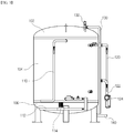
- the drain hole 150 is a place to discharge the fluid when needs to discharge the fluid in the heat storage tank 100. In general, it is located on the lower cap 106 of the heat storage tank 100 for smooth fluid discharge. In one embodiment of the present invention shown in FIG. 6 , the drain hole 150 is formed in the center of the lower cap 106. However, as described above, the position of the drain hole 150 may be moved to the side portion of the heat storage tank 100 rather than the lower portion of the heat storage tank 100 so that installation of the support 108 is not required.
- the fuel cell heat exchanger 200 discharges the waste heat generated in the fuel cell itself by using system water. That is, heat exchange is performed between the coolant circulating inside the fuel cell and the system water supplied from the heat storage tank, so that the heat of the coolant is transferred to the system water, thereby cooling the inside of the fuel cell.
- the fuel cell heat exchanger 200 corresponds to a source of heat when viewed from the standpoint of a heat storage tank.
- the heat exchanger 300 for hot water supply discharges heat to the outside through the circulation water for heat exchange that has absorbed the waste heat stored in the heat storage tank 100. At this time, the discharged heat may be supplied as hot water to a user by heating the external low-temperature water. Therefore, the heat exchanger 300 for hot water supply corresponds to a means for discharging heat when viewed from the standpoint of a heat storage tank.
- thermosensors there are temperature sensors in all flow paths that exist in the entire system, and temperature sensors are installed at the top, middle, and bottom of the body part 104 of the heat storage tank 100, respectively.
- system water outlet pipe 112 near the heat storage tank 100 there is a circulation passage circulating to a radiator 402, and the system water discharged from the heat storage tank 100 circulates in the circulation passage and discharge the heat through the radiator 402. Accordingly, the temperature of the system water can be lowered to form the system water in a lower temperature state. That is, the radiator 402 corresponds to another heat dissipation source of the heat storage tank 100.
- the system water flows into the fuel cell heat exchanger 200 to exchange heat with the waste heat generated from the fuel cell, and then the system water that has been converted in a high temperature state by absorbing the waste heat is introduced into the upper portion of the heat storage tank 100. Therefore, the heat storage tank 100 is configured to maintain a thermal balance while radiating the heat supplied from multiple fuel cells through the heat exchanger 300 for hot water supply, the radiator 402, the hot water discharge pipe 130, and the like.
- a control means is additionally provided to control which heat source to receive heat from and through which heat dissipation means to dissipate heat. At this time, the priority between the heat dissipation means may be determined by comprehensively considering the operation efficiency of the fuel cell, the stability of the system, whether a user requests hot water supply, and the like.
- FIG. 7 shows a schematic configuration of the fuel cell system.
- the system water that has absorbed waste heat from each of the fuel cell heat exchangers 200 in a high temperature state flows into the upper portion of the heat storage tank 100 through the system water inlet pipe 110 integrated at one point.
- the fluid supplied through the fluid supply pipe 140 is basically existed in the heat storage tank 100.
- the fluid existing in the heat storage tank 100 serves to store the waste heat from the fuel cell heat exchanger 200 by exchanging heat with the high-temperature system water.
- the system water introduced in a low temperature state is introduced into the heat storage tank 100 and serves to lower the temperature of the lower portion of the heat storage tank 100.
- the fluid at the lower portion becomes a low temperature state, and eventually, the low-temperature system water is discharged through the system water outlet pipe 112 connected to the lower portion of the heat storage tank 100.
- the system water transfer pump 114 is provided to help discharge the system water.
- the system water is circulated to the fuel cell heat exchanger 200 and the heat storage tank 100 through the system water transfer pump 114.
- the radiator 402 is installed in the system water inlet pipe 110 near the heat storage tank 100 to make the incoming system water in a low temperature state.
- the system water inlet pipe 110 is branched at any one point to supply low-temperature system water to each of the fuel cell heat exchangers 200.
- At least one fuel cell is installed, and the fuel cell includes a fuel cell controller.
- the fuel cell is connected to the fuel cell heat exchanger 200 through a flow path, and the fuel cell heat exchanger 200 is connected to the system water outlet pipe 112 and the system water inlet pipe 110.
- a control valve is installed on the system water inlet pipe 110, and the control valve is opened and closed by receiving a signal from the fuel cell controller.
- the system water transfer pump 114 is installed on the system water outlet pipe 112, and a heat exchanger 400 for heat dissipation is installed on the system water outlet pipe 112.
- the heat exchanger 400 for heat dissipation and the radiator 402 are connected through a circulation water flow path for heat dissipation, and the heat exchanged by the heat exchanger 400 for heat dissipation is discharged to an outside through the radiator 402.
- the heat exchanger 400 for heat dissipation is disposed in a stage immediately preceding the fuel cell heat exchanger 200 on the system water flow path, and the system water in a state in which the temperature is maintained as low as possible can be supplied to the fuel cell heat exchanger 200.
- the fluid may be introduced into the heat storage tank 100 or the fluid may be discharged from the heat storage tank 100.
- the control valve is opened and closed by receiving a signal from the heat storage tank controller.
- the temperature of the external low-temperature water may be increased, which will be described later.
- the waste heat in the heat storage tank 100 may be supplied in the heat exchanger 300 for hot water supply for circulation. Accordingly, the external low-temperature water can be heated, and the heated low-temperature water can be supplied to a user as hot water.
- the flow rate sensor 500 installed in the external low-temperature water flow path senses the flow rate in the water channel.
- the flow rate sensor 500 that has sensed the flow rate transmits a flow rate detection signal to the heat storage tank controller. If the temperature in the heat storage tank 100 detected by the temperature sensor installed in the heat storage tank 100 is higher than a certain temperature, the heat storage tank controller transmits an operation signal to the system water circulation pump for hot water 124.
- the certain temperature may change flexibly in some cases, and is not a fixed value.
- the system water circulation pump for hot water 124 operates, the high-temperature circulation water stored in the heat storage tank is moved to the heat exchanger for hot water supply 400 through the system water supply pipe for hot water 120 and dissipates heat at the heat exchanger for hot water supply 300. Accordingly, the user can obtain the desired hot water. If the temperature in the heat storage tank is lower than the certain temperature, the heat storage tank controller does not transmit the operation signal to the system water circulation pump for hot water 124, so that the system water circulation pump for hot water 124 does not operate. This is generally a case in which the accumulation of the waste heat in the heat storage tank is not sufficient, so that the user can use the desired hot water by receiving heat supply through the use of an external auxiliary boiler or the like.
- the fuel cell controller transmits a fuel cell operation signal to the heat storage tank controller.
- the heat storage tank controller that has received the operation signal transmits an operation signal to the system water transfer pump 114, and the system water transfer pump 114 operates accordingly.
- the temperature in the fuel cell may be controlled by a control valve provided for each fuel cell heat exchanger 200. That is, when the control valve is opened, the system water of low temperature is supplied to the fuel cell heat exchanger 200 to cool the inside of the fuel cell.
- the control valve is closed. In this case, since the system water is supplied only to the fuel cell with the control valve open, multiple fuel cells can be individually and independently cooled using one heat storage tank.
- the fuel cell In order for the fuel cell to operate efficiently, it is important to keep the system water at a low temperature. If the system water is maintained at a high temperature, the waste heat generated from the fuel cell cannot be efficiently absorbed, and the waste heat is accumulated in the fuel cell, thereby reducing the electricity generation efficiency of the fuel cell. In addition, it may cause failure of components in the fuel cell.
- the embodiment of the present invention uses the radiator 402. If the temperature sensor installed at the lower portion of the heat storage tank detects a certain temperature or higher, the radiator 402 is operated through the heat storage tank controller. If the temperature at the lower portion of the heat storage tank falls below a certain temperature due to the operation of the radiator 402, the operation of the radiator 402 is stopped.
- the radiator 402 when the radiator 402 is operated, there is heat exchange between the system water outlet pipe 112 passing through the heat exchanger for heat dissipation 400 and the flow path connected to the radiator 402, and the flow path that has absorbed the heat in the system water outlet pipe 112 transports heat by the movement of the fluid in the flow path, thereby discharging the heat transported from the radiator 402 to the outside.
- the temperature of the fluid in the system water outlet pipe 112 may be reduced through the heat dissipation.
- the system water may be heated to an extent that exceeds the heat dissipation capacity of the radiator 402.
- high-temperature system water can be directly discharged to an outside without using a heat exchanger or the like. That is, if the temperature sensor installed at the lower portion of the heat storage tank 100 detects a certain temperature or higher, the control valve of the hot water discharge pipe 130 is opened through the heat storage tank controller, and accordingly, the high-temperature system water distributed at the upper portion of the heat storage tank 100 is discharged directly to the outside.
- the control valve of the fluid supply pipe 140 is opened through the heat storage tank controller, so that low-temperature water flows in and the water level will be filled. If the temperature in the heat storage tank 100 falls below a certain temperature during the above processes, the control valves of the hot water discharge pipe 130 and the fluid supply pipe 140 are closed through the heat storage tank controller.
- the hot water discharging method When both the radiator 402 and the hot water discharging method are used depending on the situation, priority is set for the use of the radiator 402. If the radiator 402 operates as described above, but the radiator 402 is operated for more than a certain time set in the controller, the hot water discharging method is used as the operation of the heat storage tank controller. In this case, the hot water discharging method operates in the same manner as described above, and if the temperature in the heat storage tank falls below a certain temperature by the radiator 402 and the hot water discharging method, the radiator 402 and the hot water discharging method are stopped.
- the system water transfer pump 114 if the operation of the system water transfer pump 114 is also stopped in a state in which the fuel cell system is stopped, the temperature of the system water stored in the lower portion of the heat storage tank 100 may be lowered. In particular, there may be a risk of freezing and breaking depending on external temperature conditions. In this case, if it is determined by the heat storage tank controller that there is a risk of freezing, the two pumps 114 and 124 may be operated to prevent freezing. In other words, the system water is continuously circulated so that freezing can be prevented even if there is no heat source.
- the present invention has industrial applicability for fuel cell systems.
Landscapes
- Life Sciences & Earth Sciences (AREA)
- Engineering & Computer Science (AREA)
- Manufacturing & Machinery (AREA)
- Sustainable Development (AREA)
- Sustainable Energy (AREA)
- Chemical & Material Sciences (AREA)
- Chemical Kinetics & Catalysis (AREA)
- Electrochemistry (AREA)
- General Chemical & Material Sciences (AREA)
- Heat-Pump Type And Storage Water Heaters (AREA)
- Fuel Cell (AREA)
Applications Claiming Priority (2)
| Application Number | Priority Date | Filing Date | Title |
|---|---|---|---|
| KR1020180146205A KR102204693B1 (ko) | 2018-11-23 | 2018-11-23 | 복수 개의 연료전지를 포함하는 연료전지 시스템 |
| PCT/KR2019/011844 WO2020105855A1 (fr) | 2018-11-23 | 2019-09-11 | Système de pile à combustible comprenant une pluralité de piles à combustible |
Publications (2)
| Publication Number | Publication Date |
|---|---|
| EP3886224A1 true EP3886224A1 (fr) | 2021-09-29 |
| EP3886224A4 EP3886224A4 (fr) | 2022-10-12 |
Family
ID=70774563
Family Applications (1)
| Application Number | Title | Priority Date | Filing Date |
|---|---|---|---|
| EP19886526.3A Withdrawn EP3886224A4 (fr) | 2018-11-23 | 2019-09-11 | Système de pile à combustible comprenant une pluralité de piles à combustible |
Country Status (4)
| Country | Link |
|---|---|
| EP (1) | EP3886224A4 (fr) |
| KR (1) | KR102204693B1 (fr) |
| CN (1) | CN113169354B (fr) |
| WO (1) | WO2020105855A1 (fr) |
Cited By (1)
| Publication number | Priority date | Publication date | Assignee | Title |
|---|---|---|---|---|
| FR3168083A1 (fr) * | 2024-10-28 | 2026-05-01 | Eo Concept | Système de régulation thermique pour un ensemble de dispositifs électrochimiques à piles à combustible |
Families Citing this family (4)
| Publication number | Priority date | Publication date | Assignee | Title |
|---|---|---|---|---|
| CN114068986B (zh) * | 2021-11-09 | 2023-03-31 | 广东电网有限责任公司广州供电局 | 一种固态合金储氢与多电堆燃料电池热管理系统 |
| KR102623413B1 (ko) * | 2023-09-19 | 2024-01-09 | 에이치디씨랩스 주식회사 | 연료전지 열효율화 통합패키지 시스템 및 방법 |
| KR102643049B1 (ko) * | 2023-11-20 | 2024-03-04 | 삼중테크 주식회사 | 연료전지 배열가스의 열 에너지 회수 시스템 |
| KR102910187B1 (ko) | 2023-11-29 | 2026-01-12 | 아크로랩스 주식회사 | 내구성이 증대된 수전해 시스템 |
Family Cites Families (9)
| Publication number | Priority date | Publication date | Assignee | Title |
|---|---|---|---|---|
| JP4357270B2 (ja) * | 2003-11-04 | 2009-11-04 | 東京瓦斯株式会社 | 燃料電池排熱利用システム及びその運転方法 |
| KR100700548B1 (ko) | 2005-08-25 | 2007-03-28 | 엘지전자 주식회사 | 연료전지의 난방/온수 제어 장치 및 그 방법 |
| JP5109252B2 (ja) * | 2005-12-05 | 2012-12-26 | 三菱マテリアル株式会社 | 燃料電池 |
| KR100726431B1 (ko) * | 2006-05-18 | 2007-06-08 | 지에스퓨얼셀 주식회사 | 연료전지 코제너레이션 시스템용 축열탱크 |
| KR100750057B1 (ko) * | 2006-09-04 | 2007-08-16 | 에스케이에너지 주식회사 | 공동주택 연료전지 시스템 및 그 운영방법 |
| KR100911055B1 (ko) * | 2007-10-19 | 2009-08-06 | (주)퓨얼셀 파워 | 연료전지 시스템의 열회수 장치 |
| JP6153771B2 (ja) * | 2013-05-30 | 2017-06-28 | 本田技研工業株式会社 | 廃熱回収システム |
| JP2015022864A (ja) * | 2013-07-18 | 2015-02-02 | パナソニック株式会社 | 燃料電池システム |
| US10305126B2 (en) * | 2015-12-03 | 2019-05-28 | Panasonic Intellectual Property Management Co., Ltd. | Fuel cell system |
-
2018
- 2018-11-23 KR KR1020180146205A patent/KR102204693B1/ko active Active
-
2019
- 2019-09-11 WO PCT/KR2019/011844 patent/WO2020105855A1/fr not_active Ceased
- 2019-09-11 EP EP19886526.3A patent/EP3886224A4/fr not_active Withdrawn
- 2019-09-11 CN CN201980077113.2A patent/CN113169354B/zh active Active
Cited By (1)
| Publication number | Priority date | Publication date | Assignee | Title |
|---|---|---|---|---|
| FR3168083A1 (fr) * | 2024-10-28 | 2026-05-01 | Eo Concept | Système de régulation thermique pour un ensemble de dispositifs électrochimiques à piles à combustible |
Also Published As
| Publication number | Publication date |
|---|---|
| KR20200060963A (ko) | 2020-06-02 |
| CN113169354B (zh) | 2024-04-09 |
| CN113169354A (zh) | 2021-07-23 |
| WO2020105855A1 (fr) | 2020-05-28 |
| EP3886224A4 (fr) | 2022-10-12 |
| KR102204693B1 (ko) | 2021-01-18 |
Similar Documents
| Publication | Publication Date | Title |
|---|---|---|
| KR102204693B1 (ko) | 복수 개의 연료전지를 포함하는 연료전지 시스템 | |
| KR20120129890A (ko) | 격벽들을 구비한 어큐뮬레이터 탱크 | |
| JP5704398B2 (ja) | 熱回収装置、コージェネレーションシステム、並びに、配管の誤接続検知方法 | |
| JP2005327494A (ja) | 集合住宅用燃料電池発電システム及びこれの運転方法 | |
| CN119419410A (zh) | 热管理装置和储能柜 | |
| JP2005147494A (ja) | 多温度蓄熱槽およびそれを用いた蓄熱システム | |
| JP2005141913A (ja) | 燃料電池排熱利用システム及びその運転方法 | |
| US20250035320A1 (en) | Water heating system and a controller therefor | |
| JP6662374B2 (ja) | 冷媒供給装置、それを用いた相変化冷却装置、および冷媒供給方法 | |
| CN217957570U (zh) | 冷却系统 | |
| JP5069490B2 (ja) | 大気開放型蓄熱装置 | |
| KR100990034B1 (ko) | 대기상태를 가지는 드레인 다운식 밀폐형 태양열 시스템의 제어방법 | |
| JP2011000922A (ja) | 燃料電池搭載車両の燃料タンク温度管理装置 | |
| JP2004125289A (ja) | 潜熱蓄熱式冷熱源設備、及び、潜熱蓄熱式温熱源設備 | |
| KR200435845Y1 (ko) | 완전밀폐식 태양열급탕난방기 | |
| CN214249761U (zh) | 余热回收利用系统 | |
| KR101207427B1 (ko) | 연료전지 열병합 시스템 물탱크의 정유량 공급 및 배출 장치와 그 제어방법 | |
| JP4784824B2 (ja) | 貯留型熱源装置 | |
| JP2005140393A (ja) | 貯湯式給湯装置 | |
| JP2011257130A (ja) | 排熱回収装置 | |
| KR100989994B1 (ko) | 드레인 다운식 밀폐형 태양열 시스템 및 그 제어방법 | |
| CN223108967U (zh) | 一种储能装置温控系统及储能装置 | |
| CN114061309A (zh) | 一种坩埚冷却供水闭式循环系统及其运行方法 | |
| KR102946647B1 (ko) | 복층 구조 연료 전지의 냉각 시스템 및 냉각 방법 | |
| CN222463086U (zh) | 储能柜 |
Legal Events
| Date | Code | Title | Description |
|---|---|---|---|
| STAA | Information on the status of an ep patent application or granted ep patent |
Free format text: STATUS: THE INTERNATIONAL PUBLICATION HAS BEEN MADE |
|
| PUAI | Public reference made under article 153(3) epc to a published international application that has entered the european phase |
Free format text: ORIGINAL CODE: 0009012 |
|
| STAA | Information on the status of an ep patent application or granted ep patent |
Free format text: STATUS: REQUEST FOR EXAMINATION WAS MADE |
|
| 17P | Request for examination filed |
Effective date: 20210518 |
|
| AK | Designated contracting states |
Kind code of ref document: A1 Designated state(s): AL AT BE BG CH CY CZ DE DK EE ES FI FR GB GR HR HU IE IS IT LI LT LU LV MC MK MT NL NO PL PT RO RS SE SI SK SM TR |
|
| DAV | Request for validation of the european patent (deleted) | ||
| DAX | Request for extension of the european patent (deleted) | ||
| A4 | Supplementary search report drawn up and despatched |
Effective date: 20220909 |
|
| RIC1 | Information provided on ipc code assigned before grant |
Ipc: H01M 8/249 20160101ALI20220905BHEP Ipc: H01M 8/04029 20160101ALI20220905BHEP Ipc: H01M 8/04007 20160101AFI20220905BHEP |
|
| STAA | Information on the status of an ep patent application or granted ep patent |
Free format text: STATUS: THE APPLICATION IS DEEMED TO BE WITHDRAWN |
|
| 18D | Application deemed to be withdrawn |
Effective date: 20250401 |