EP3886253A1 - Antenne à guide d'onde à coin de diélectrique et conducteur magnétique artificiel (amc) directif - Google Patents
Antenne à guide d'onde à coin de diélectrique et conducteur magnétique artificiel (amc) directif Download PDFInfo
- Publication number
- EP3886253A1 EP3886253A1 EP21167348.8A EP21167348A EP3886253A1 EP 3886253 A1 EP3886253 A1 EP 3886253A1 EP 21167348 A EP21167348 A EP 21167348A EP 3886253 A1 EP3886253 A1 EP 3886253A1
- Authority
- EP
- European Patent Office
- Prior art keywords
- antenna
- amc
- feed structure
- dielectric
- wall
- Prior art date
- Legal status (The legal status is an assumption and is not a legal conclusion. Google has not performed a legal analysis and makes no representation as to the accuracy of the status listed.)
- Pending
Links
- 239000004020 conductor Substances 0.000 title claims description 21
- 230000007704 transition Effects 0.000 claims abstract description 27
- 239000003989 dielectric material Substances 0.000 claims description 3
- 238000003780 insertion Methods 0.000 claims description 3
- 230000037431 insertion Effects 0.000 claims description 3
- 230000000737 periodic effect Effects 0.000 claims description 3
- 239000000523 sample Substances 0.000 claims description 3
- 230000005540 biological transmission Effects 0.000 abstract description 3
- 238000004891 communication Methods 0.000 description 24
- 238000000034 method Methods 0.000 description 10
- 239000006185 dispersion Substances 0.000 description 9
- 238000000429 assembly Methods 0.000 description 3
- 230000000712 assembly Effects 0.000 description 3
- 238000002059 diagnostic imaging Methods 0.000 description 3
- 230000000694 effects Effects 0.000 description 3
- 239000000463 material Substances 0.000 description 3
- 230000004044 response Effects 0.000 description 3
- 238000003491 array Methods 0.000 description 2
- MPTQRFCYZCXJFQ-UHFFFAOYSA-L copper(II) chloride dihydrate Chemical compound O.O.[Cl-].[Cl-].[Cu+2] MPTQRFCYZCXJFQ-UHFFFAOYSA-L 0.000 description 2
- 229910010272 inorganic material Inorganic materials 0.000 description 2
- 239000011147 inorganic material Substances 0.000 description 2
- 239000011368 organic material Substances 0.000 description 2
- 238000004088 simulation Methods 0.000 description 2
- 239000000654 additive Substances 0.000 description 1
- 230000000996 additive effect Effects 0.000 description 1
- 230000001413 cellular effect Effects 0.000 description 1
- 230000008878 coupling Effects 0.000 description 1
- 238000010168 coupling process Methods 0.000 description 1
- 238000005859 coupling reaction Methods 0.000 description 1
- 238000010586 diagram Methods 0.000 description 1
- 238000005516 engineering process Methods 0.000 description 1
- 238000005530 etching Methods 0.000 description 1
- 238000004519 manufacturing process Methods 0.000 description 1
- 230000006855 networking Effects 0.000 description 1
- 238000005457 optimization Methods 0.000 description 1
- 238000000059 patterning Methods 0.000 description 1
- 230000008569 process Effects 0.000 description 1
- 230000001902 propagating effect Effects 0.000 description 1
- 230000009467 reduction Effects 0.000 description 1
Images


Classifications
-
- H—ELECTRICITY
- H01—ELECTRIC ELEMENTS
- H01Q—ANTENNAS, i.e. RADIO AERIALS
- H01Q13/00—Waveguide horns or mouths; Slot antennas; Leaky-waveguide antennas; Equivalent structures causing radiation along the transmission path of a guided wave
-
- H—ELECTRICITY
- H01—ELECTRIC ELEMENTS
- H01Q—ANTENNAS, i.e. RADIO AERIALS
- H01Q1/00—Details of, or arrangements associated with, antennas
- H01Q1/27—Adaptation for use in or on movable bodies
- H01Q1/28—Adaptation for use in or on aircraft, missiles, satellites, or balloons
- H01Q1/286—Adaptation for use in or on aircraft, missiles, satellites, or balloons substantially flush mounted with the skin of the craft
-
- H—ELECTRICITY
- H01—ELECTRIC ELEMENTS
- H01Q—ANTENNAS, i.e. RADIO AERIALS
- H01Q1/00—Details of, or arrangements associated with, antennas
- H01Q1/27—Adaptation for use in or on movable bodies
-
- H—ELECTRICITY
- H01—ELECTRIC ELEMENTS
- H01Q—ANTENNAS, i.e. RADIO AERIALS
- H01Q1/00—Details of, or arrangements associated with, antennas
- H01Q1/36—Structural form of radiating elements, e.g. cone, spiral, umbrella; Particular materials used therewith
- H01Q1/364—Structural form of radiating elements, e.g. cone, spiral, umbrella; Particular materials used therewith using a particular conducting material, e.g. superconductor
-
- H—ELECTRICITY
- H01—ELECTRIC ELEMENTS
- H01Q—ANTENNAS, i.e. RADIO AERIALS
- H01Q13/00—Waveguide horns or mouths; Slot antennas; Leaky-waveguide antennas; Equivalent structures causing radiation along the transmission path of a guided wave
- H01Q13/20—Non-resonant leaky-waveguide or transmission-line antennas; Equivalent structures causing radiation along the transmission path of a guided wave
- H01Q13/24—Non-resonant leaky-waveguide or transmission-line antennas; Equivalent structures causing radiation along the transmission path of a guided wave constituted by a dielectric or ferromagnetic rod or pipe
-
- H—ELECTRICITY
- H01—ELECTRIC ELEMENTS
- H01Q—ANTENNAS, i.e. RADIO AERIALS
- H01Q15/00—Devices for reflection, refraction, diffraction or polarisation of waves radiated from an antenna, e.g. quasi-optical devices
- H01Q15/0006—Devices acting selectively as reflecting surface, as diffracting or as refracting device, e.g. frequency filtering or angular spatial filtering devices
- H01Q15/0086—Devices acting selectively as reflecting surface, as diffracting or as refracting device, e.g. frequency filtering or angular spatial filtering devices said selective devices having materials with a synthesized negative refractive index, e.g. metamaterials or left-handed materials
Definitions
- antennas are often mounted on a surface (or "skin") of the vehicle and ideally such antennas are flush mounted since flush mounted antennas reduce aerodynamic effects for an underlying vehicle.
- an antenna beam provided by the antenna must generally point in either an aft or forward direction with respect to the vehicle, depending upon the needs of the particular application.
- an antenna comprises a dielectric wedge waveguide and a waveguide feed structure comprising artificial magnetic conductor (AMC) walls.
- AMC artificial magnetic conductor
- a dielectric wedge waveguide antenna having an impedance bandwidth which is relatively wide compared with antennas of similar size is provided.
- the antenna is also provided having end-fire gain and front-to-back ratio characteristics which are relatively high compared with conventional antennas of similar size.
- the dielectric wedge waveguide antenna can be packaged in a volume which is less (and often substantially less) than the volume of conventional antennas while at the same time achieving desired antenna characteristics.
- a dispersion relation of the AMC wall feed structure can be designed to reduce (or miniaturize) volume compared with prior art feed structures while maintaining desired operating frequency bandwidth.
- the AMC wall feed structure couples radio frequency (RF) energy to/from the dielectric wedge waveguide antenna to provide an antenna having a relatively high gain characteristic and a high front-to-back-ratio.
- RF radio frequency
- Such antennas find use in systems capable of establishing communication and data links where antennas having a relatively high end-fire gain characteristic and a high front-to-back-ratio are desirable.
- the illustrative dielectric wedge waveguide may be designed to provide relatively high end-fire gain performance. It should, of course, be appreciated that by adjusting the angle of a dielectric wedge, the antenna pattern may be steered by design to any angle from broadside to end-fire.
- the front-to-back-ratio may be greater than 15 dB while in other embodiments the front-to-back-ratio may be greater than 20 dB.
- the particular front-to-back-ratio achieved in any particular application depends upon a variety of factors including, but not limited to, the particular vehicle on which the antenna is mounted or otherwise disposed.
- a mobile vehicle or platform which includes a system provided in accordance with the concepts described herein may communicate to a deployment platform by directing an antenna beam (preferably a high gain antenna beam) back to its launch point.
- an antenna beam preferably a high gain antenna beam
- the antenna may be flush mounted to an outer surface of a vehicle thereby reducing, and ideally minimizing, its aerodynamic effect on the vehicle. Furthermore, such a volume-limited antenna can reduce, and ideally minimize, its mass impact on the vehicle (e.g. a smaller antenna may weigh less and consequently reduce the overall weight of a missile, aircraft or other vehicle on which the antenna is mounted).
- An antenna having a relatively high gain characteristic, a relatively high front-to-back ratio, and which is volume-limited is highly desirable in many applications.
- the AMC wall feed structure allows the antenna to be fully recessed (e.g. flush mounted) on a surface of a vehicle.
- the antenna is fully recessed (e.g. flush mounted) on a surface of an airborne vehicle including, but not limited to a missile, an aircraft, an unmanned aerial vehicle (UAV) or other airborne vehicle.
- UAV unmanned aerial vehicle
- the AMC feed structure is provided as a rectangular waveguide having an AMC wall.
- This illustrative embodiment provides a significant reduction in antenna volume compared with conventional designs and provides the antenna having high end-fire gain, high front-to-back ratio (e.g. greater than about 15 dB), wide VSWR2:1 BW (e.g. greater than about 15%).
- an entire antenna assembly comprising an AMC wall feed structure may be recessed into a shroud to reduce, and ideally minimize, aerodynamic impact on an aerial vehicle.
- the AMC wall feed structure utilizes a coaxial line (e.g. having a connector, such as an SMA connector for example, coupled to one end thereof) to provide a port through which RF signals may be provided to/from the antenna.
- a coaxial line e.g. having a connector, such as an SMA connector for example, coupled to one end thereof
- aperture coupling or other techniques may be used to couple RF signals to / from the feed circuits and/or the antenna.
- the antenna may be manufactured using standard printed circuit board (PCB) materials and fabrication processes and thus may be provided as a low cost antenna.
- PCB printed circuit board
- the antenna can be scaled using conventional methodologies such that different antennas can be provided for operation over a wide range of different frequency bands.
- Simulation and measured results of one illustrative antenna show high end-fire gain, high front-to-back-ratio, and very stable gain response vs. frequency, wide operating impedance bandwidth and compact size. Such characteristics are desirable for datalink systems.
- the antenna may thus be used in datalink applications requiring high end-fire gain, high front-to-back-ratio and wide impedance bandwidth.
- the dielectric wedge antenna-AMC feed assembly has a volume which is relatively small compared with the volume of antenna assemblies having similar electrical antenna characteristics.
- the small volume of the dielectric wedge antenna assembly allows the antenna to be used on relatively small missile airframes and also allows the antenna to be mounted flush within an outer surface of a mobile or stationary vehicle on which it is disposed (e.g. flush with a missile skin).
- the antenna may be used in a wide variety of different applications including, but not limited to: (1) active or passive antenna elements for missile sensor systems; (2) wireless and/or hard-wired datalinks, or communication systems requiring wide impedance bandwidth; (3) applications which require high end-fire gain and/or high front-to-back-ratio; (4) applications requiring an antenna which fits within a compact recessed volume; (5) land-based applications; (6) sea-based applications; (7) satellite communications applications; (8) handheld communication devices; and (9) commercial aircraft communications; (10) satellite digital audio radio services; and (11) medical imaging applications.
- dielectric wedge antenna-AMC feed assembly can be used in handheld communication devices as well as in commercial aircraft communications. Such an assembly also finds use in automobiles for personal communication, cellular signals, traffic updates as well as for emergency response communication.
- a dielectric wedge antenna may include one or more of the following features independently or in combination with another feature to include: an artificial magnetic conductor (AMC) wall feed structure provided a having a number of unit cells and a transition coupled between the AMC wall feed structure and a dielectric wedge waveguide.
- AMC artificial magnetic conductor
- a width and a height of said dielectric wedge are each less than a wavelength at the center frequency of the antenna.
- the dielectric wedge is provided having a length corresponding to about 1.2 ⁇ , a width corresponding to about 0.7 A, and a height corresponding to about 0.3 ⁇ at a center frequency of the antenna.
- a width and a height of the AMC wall feed structure are each less than a wavelength at the center frequency of the antenna.
- the AMC wall feed structure is provided having a length corresponding to about 0.5 A, a width corresponding to about 0.4 ⁇ , and a height corresponding to about 0.2 ⁇ at a center frequency of the antenna.
- the AMC wall feed structure comprises: a plurality of unit cells, each unit cell comprising a pair of sidewall portions having AMC portions provided therein and spaced apart by a predetermined distance.
- the AMC wall feed structure comprises: a plurality of unit cells, each unit cell comprising a pair of sidewall portions having AMC portions provided therein and spaced apart by a predetermined distance with a region between the sidewall pairs provided as a dielectric filled region.
- the AMC wall feed structure comprises: a pair of sidewalls, each of said sidewalls provided from a plurality of unit cells each having AMC portions provided therein and spaced apart by a predetermined distance with a region between the sidewall pairs; a top conductive wall disposed over a top surface of said pair of sidewalls; a bottom conductive wall; and a conductive end wall wherein said top, bottom, end and side walls form a waveguide being open on one end exposed to said transition.
- the transition comprises: a conductive cavity defined by sidewalls and a bottom surface, the conductive cavity having a dielectric material disposed in at least a portion thereof and being open on a first end facing said AMC wall feed structure and open on a second, opposite end facing said dielectric wedge.
- the AMC wall feed structure comprises: a pair of sidewalls, each of said sidewalls provided from a plurality of unit cells each having AMC portions provided therein and spaced apart by a predetermined distance with a region between the sidewall pairs; a top conductive wall disposed over a top surface of said pair of sidewalls; a bottom conductive wall; and a conductive end wall wherein said top, bottom, end and side walls form a waveguide being open on one end exposed to said transition.
- the AMC wall feed structure comprises a feed probe disposed in a center of the conductive wall of said waveguide.
- a width and a height of the dielectric wedge are each less than a wavelength at the center frequency of the antenna.
- the dielectric wedge is provided having a length corresponding to about 1.2 ⁇ , a width corresponding to about 0.7 ⁇ , and a height corresponding to about 0.3 ⁇ at a center frequency of the antenna.
- a width and a height of said AMC wall feed structure are each less than a wavelength at the center frequency of the antenna.
- the AMC wall feed structure is provided having a length corresponding to about 0.5 ⁇ , a width corresponding to about 0.4 ⁇ , and a height corresponding to about 0.2 ⁇ at a center frequency of the antenna.
- the antenna is configured for insertion into a conductive cavity within an outer skin of a vehicle; and the dielectric wedge has a height that allows the antenna to be mounted in the conductive cavity substantially flush to the outer skin of the vehicle.
- the vehicle includes one of: a ground vehicle, a watercraft, an aircraft, and a spacecraft.
- the dielectric wedge is provided having a length corresponding to about 1.2 ⁇ , a width corresponding to about 0.7 ⁇ , and a height corresponding to about 0.3 ⁇ at a center frequency of the antenna.
- a width and a height of the AMC wall feed structure are each less than about a wavelength at the center frequency of the antenna.
- the AMC wall feed structure is provided having a length corresponding to about 0.5 A, a width corresponding to about 0.4 ⁇ , and a height corresponding to about 0.2 ⁇ at a center frequency of the antenna.
- the subject matter described herein relates to dielectric wedge antenna designs capable of providing antennas having a relatively small, low-profile package while still having relatively high gain, fixed beam steering, wide angular coverage and wide bandwidth characteristics.
- the antenna designs described herein are particularly well suited for use in applications in which flush mounting of antennas is either desired and/or required (e.g., airborne applications, conformal arrays, etc.).
- the antenna designs described herein are also well suited for use in other applications where small antenna size is desired, such as hand held wireless communicators and wireless networking products.
- the antenna designs described herein may be used in wireless or wired datalinks systems.
- CCS Cartesian coordinate system
- an antenna comprising a feed structure having artificial magnetic conductor (AMC) walls coupled to a dielectric wedge waveguide antenna.
- AMC artificial magnetic conductor
- FTBR front-to-back ratio
- AMC wall feed structure significantly reduces the volume of the antenna. In some embodiments, for the same application, the volume is reduced by a factor of 2.6 compared with conventional designs.
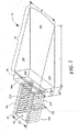
- antenna 10 is mounted (or otherwise disposed) on a platform (or vehicle) 12.
- antenna 10 comprises an AMC wall feed structure coupled to a dielectric wedge antenna.
- platform 12 is provided as a portion of a missile body.
- antenna 10 may correspond to a rear reference antenna or a fuse antenna, for example.
- platform 12 may also correspond to an aircraft body or any stationary or moving (or movable) platform.
- platform 12 is shown having a generally conical shape, in general, platform 12 may be provided having any size and/or shape (e.g. cylindrical or any other geometric shape) selected to suit the needs of any particular application (including, but not limited to, a cylindrical shape, a box shape, a prism shape, a pyramidal shape with any of such shapes having flat or curved surfaces).
- any size and/or shape e.g. cylindrical or any other geometric shape selected to suit the needs of any particular application (including, but not limited to, a cylindrical shape, a box shape, a prism shape, a pyramidal shape with any of such shapes having flat or curved surfaces).
- antenna 10 is provided in a relatively small physical package having a relatively small volume which allows the antenna 10 to be mounted flush with respect to a surface of an outer covering 12a (or "skin") of the platform 12 (e.g. a missile or other vehicle) in airborne applications, flush mounted antennas reduce, and ideally minimize, aerodynamic effects for an underlying moving platform.
- a volume-limited antenna can reduce or ideally minimize mass impact (that is, a smaller antenna may weigh less and consequently reduce the overall weight of the missile or aircraft in which it is mounted).
- antenna 10 is provided from an AMC wall feed structure coupled to a dielectric wedge waveguide antenna. This results in antenna 10 having a wide bandwidth characteristic, good directionality and a high gain characteristic which help satisfy ever increasing requirements for communication distance and data rate.
- the antenna 10 is mounted on a missile body and communicates to a deployment platform (e.g. a missile launch point, not shown in Fig. 1 ).
- a deployment platform e.g. a missile launch point, not shown in Fig. 1 .
- the antenna gain must be directed toward its launch point (i.e. the antenna beam must be generally rearward facing with respect to the direction of missile travel).
- antenna 10 To use antenna 10 on a missile (or other airborne vehicle) and operate for all data link functions, it is desirable for the antenna 10 to have a high end-fire gain characteristic, a high front-to-back-ratio, a wide impedance bandwidth characteristic, and also be volume-limited and capable of being flush-mounted with the missile skin.
- the antenna 10 may be used in a wide variety of different applications including, but not limited to: (1) active or passive antenna elements for missile sensor system; (2) wireless and/or hard-wired data links, or communication systems requiring wide impedance bandwidth; (3) high end-fire gain, high front-to-back-ratio, and applications requiring a compact recessed volume; (4) land-based applications; (5) sea-based applications; (6) satellite communications applications; (7) handheld communication devices; and (8) commercial aircraft communications; (9) satellite digital audio radio services; and (10) medical imaging.
- active or passive antenna elements for missile sensor system (2) wireless and/or hard-wired data links, or communication systems requiring wide impedance bandwidth; (3) high end-fire gain, high front-to-back-ratio, and applications requiring a compact recessed volume; (4) land-based applications; (5) sea-based applications; (6) satellite communications applications; (7) handheld communication devices; and (8) commercial aircraft communications; (9) satellite digital audio radio services; and (10) medical imaging.
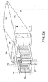
- antenna 12 is provided from a dielectric wedge waveguide 14 (also sometimes referred to as “dielectric wedge 14" or more simply “wedge 14") having an AMC wall feed structure 15 coupled thereto through a transition 16 (e.g. an impedance transformer to match the impedance of the AMC feed structure 15 to dielectric wedge 14 so as to ensure efficient transmission of RF signals between the feed 15 and the dielectric wedge 14).
- a dielectric wedge waveguide 14 also sometimes referred to as “dielectric wedge 14" or more simply “wedge 14”
- transition 16 e.g. an impedance transformer to match the impedance of the AMC feed structure 15 to dielectric wedge 14 so as to ensure efficient transmission of RF signals between the feed 15 and the dielectric wedge 14.
- the antenna having an AMC walls feed structure and a rectangular waveguide shape reduces both the length and width of the feed compared with a length and width required by conventional waveguide feed circuits for the same application. Consequently, use of the AMC walls feed structure reduces, and in some cases significantly reduces, the volume required to feed the dielectric wedge 14. In some embodiments, the volume is reduced by more than a factor of about 2 compared with the volume of conventional antenna designs. In some embodiments, the volume is reduced by a factor of about 2.6 compared with the volume of conventional antenna designs.
- Dielectric wedge 14 may be provided from any organic or inorganic material having desired physical (e.g. mechanical) and electrical properties (e.g. relative dielectric constant, permittivity, etc).
- dielectric wedge 14 is provided having top and bottom surfaces 14a, 14b, side surfaces 14c, 14d as well as a length L, a width W and a height H.
- Surfaces 14b, 14c, 14d are electrically conductive (e.g. by having a conductive material disposed or otherwise provided thereon).
- the length L, width W and height H of dielectric wedge 14 are selected in accordance with a variety of factors, including but not limited to the physical and electrical characteristics of the wedge as well as a desired operating frequency to meet the requirements of a particular application. Those of ordinary skill in the art will understand how to select an appropriate wedge material and wedge dimension to achieve desired electrical and mechanical characteristics for a particular application.
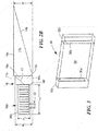
- Transition 16 comprises a dielectric portion 17a having a conductive material disposed or otherwise provided thereon.
- Dielectric 17a ( Fig. 2B ) is provided having a shape such that region 17b ( Fig. 2B ) of transition 16 is air-filled.
- the angle of surface 17 ( Fig. 2B ) is selected to help provide a desired impedance match between RF signals propagating between feed structure 15 and wedge 14.
- the dielectric portion 17a of transition 16 may be provided from any organic or inorganic material having desired physical (e.g. mechanical) and electrical properties (e.g. relative dielectric constant, permittivity, strength characteristics of the material, operating frequency, etc).
- transition 16 is provided having top and bottom surfaces 16a, 16b, side surfaces 16c, 16d, front and back surfaces 16e, 16f as well as a length L1, a width W1 (which in this illustrative embodiment is equal to width W) and a height H1 ( Fig. 2B ).
- Portions of surfaces 16a, 16c, 16d are electrically conductive (e.g. by having a conductive material disposed or otherwise provided thereon).
- the length L1, width W1 and height H1 of transition 16 are selected in accordance with a variety of factors, including but not limited to the physical and electrical characteristics of the wedge 14 and feed structure 15 as well as a desired operating frequency to meet the requirements of a particular application.
- transition 16 is here implemented using a particular structure, those of ordinary skill in the art will appreciate that any transition or structure capable of appropriately matching the impedance of AMC feed section 15 to the impedance of wedge 14 may be used. Those of ordinary skill in the art will appreciate that there are many ways (i.e. a wide variety of techniques and structures) to implement such a transition.
- AMC feed structure 15 is provided from first and second side walls 18a, 18ba which are disposed against a surface 16f of transition 16.
- a conductive end wall 20 is disposed against second ends of first and second side walls 18a, 18ba and top and bottom walls 21a, 21b are also disposed over top and bottom edges, respectively, of side walls 18a, 18b to thus form a waveguide cavity 22.
- a center conductor portion of a coaxial line 23 projects into the cavity 22 to thus provide a feed through which RF signals may be coupled into and out of the cavity 22. It should, of course, be appreciated that although a vertical coaxial line is here shown to feed the waveguide in the illustrative embodiment of Figs. 2-2B , other waveguide feeds (including, but not limited to aperture coupled feeds) may also be used.
- the waveguide is thus provided as a rectangular waveguide having an AMC walls feed structure.
- the waveguide may be provided as an air-filled waveguide, a dielectric filled waveguide or a partially dielectrically filled waveguide.
- AMC feed structure 15 is provided having a length L2, a width W2 and a height H2.
- the length L2, width W2 and height H2 of transition 16 are selected in accordance with a variety of factors.
- the following parameters were used as design parameters to design the dispersion relation of the AMC feed structure, that is, to reduce the cut-off frequency of the miniaturized waveguide to be below the desired operation frequency: width of waveguide, length of waveguide, height of waveguide, dielectric constant of waveguide (in this case air), dielectric constant of AMC side wall, thickness of AMC sidewall, width of copper trace of AMC sidewall, length of copper trace of AMC sidewall, and finally the number of AMC cells, (in the illustrative example of Figs. 2-2B , twelve cells were used).
- An eigenmode solver of a commercially available computational electromagnetic solver, e.g. High Frequency Structure Simulator or HFSS from Ansys
- Each of the above parameters were then optimized to provide the desired dispersion relation.
- the width and a height of the dielectric wedge are each less than a wavelength at the center frequency of the antenna.
- the dielectric wedge is provided having a length corresponding to about 1.2 A, a width corresponding to about 0.7 ⁇ , and a height corresponding to about 0.3 A at a center frequency of the antenna. In other frequency ranges, the dimensions may differ from that described above. It has been found that the length of the wedge could be made shorter depending on how much steering one desires. It has also been found that making the length of the wedge longer than about 1.2 A was found to not increase the amount of steering while making the length of the wedge shorter than 1.2 ⁇ resulted in not quite as much steering.
- a length, width and height of the AMC wall feed structure are each less than a wavelength at the center frequency of the antenna.
- the AMC wall feed structure is provided having a length corresponding to about 0.5 ⁇ , a width corresponding to about 0.4 ⁇ , and a height corresponding to about 0.2 ⁇ at a center frequency of the antenna. In other frequency ranges, the dimensions may differ from that described above. It was found that the length could be further optimized, but to achieve such optimization a trade-off must be made with respect to performance. The same is true with respect to the width. For example, it was found that it is possible to provide an AMC wall feed structure having a width which is less than that described above, but that doing so results in an antenna having a reduced bandwidth.
- a length and width of the transition is less than a wavelength at the center frequency of the antenna.
- a length of the transition corresponds to about 0.15 ⁇ and a width of the transition matches the width of the dielectric wedge at a center frequency of the antenna.
- sidewalls 18a, 18b comprise a plurality of periodic magnetic conductor sections 30 (also referred to as “unit cell sections 30" or more simply “unit cells 30").
- Each unit cell 30 comprises a pair of sidewall portions 32a, 32b having AMC portions 34a, 34b embedded or otherwise provided therein.
- the walls are spaced by a region 34 which may be provided as an air-filled region, a dielectric filled region or a partially dielectrically filled region.
- the unit cell may be fabricated using conventional printed circuit board technology.
- a dielectric board 32a, 32b e.g. of the type manufactured by Rogers Corporation, for example
- a conductive material 36a, 36b e.g. copper or other suitable conductor
- the opposite surface of the board is substantially free of any conductive material.
- the AMC sidewalls 32a, 32b are specifically designed to reduce the cut-off frequency to be below the desired operating frequency of a miniaturized waveguide.
- the number of unit cells, (e.g. 12) was empirically determined through simulation and selecting a balance of impedance bandwidth, front-to-back-ratio, and physical length appropriate for a desired application.
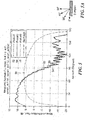
- a plot of input reflection coefficient (S11) of an illustrative antenna design shows that a wide impedance bandwidth is achieved in the antenna achieving a return loss greater than about 15 db over about a 16% frequency bandwidth and a return loss greater than about 17.5 db over about a 10% frequency bandwidth.
- Curve 40 is provided from simulated data while curves 42-26 are provided from measured data.
- a plot of measured realized gain for a standard patch antenna (curve 50) and three different dielectric wedge waveguide antenna designs (curves 52-56) is shown.
- the AMC wall feed antenna has an end-fire gain and front-to-back ratio, which is relatively high compared to end-fire gain and front-to-back ratios of traditional designs.
- Fig. 6 is a plot of both simulated and measured antenna gain vs. frequency in four different azimuth planes (0 degrees, +15 degrees, +30 degrees and +180 degrees) for an illustrative antenna design. The simulated results are shown over a 20 percent frequency range. Curves 60-646 correspond to simulated data while curves 68-72 correspond to measure data. The plot shows that over a desired frequency range, the antenna provides very stable high end-fire gain and high front to back ratio vs. frequency.
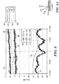
- Figs. 7 and 7A illustrate a simulated dispersion diagram which conveys, to one of ordinary skill in the art, an understanding of how to design dispersion relation.
- a dispersion relation of the AMC wall feed structure can be designed to reduce (or miniaturize) volume compared with prior art feed structures while maintaining desired operating frequency bandwidth.
- Fig 7 shows the final design of the dispersion relation of the AMC wall feed structure described above in conjunction with Figs. 2-2B .
- the mounting surface 112 may be the exterior skin of a vehicle or other mounting platform.
- the antenna assemblies 10 may be flush mounted within the various cavities to reduce problems related to, for example, wind drag. In some embodiments, however, flush mounting is not used.
- One or more beamformers may be coupled to the various antenna assemblies for use in forming beams using the various antenna elements.
- the techniques and structures described herein may be used, in some implementations, to generate conformal antennas or antenna arrays that conform to a curved surface on the exterior of a mounting platform (e.g., a missile, an aircraft, etc.).
- a mounting platform e.g., a missile, an aircraft, etc.
- the structures described above can be re-optimized for a conformal cavity.
- Techniques for adapting an antenna design for use in a conformal application are well known in the art and typically include re-tuning the antenna parameters for the conformal surface.
- the antennas may be used as active or passive antenna elements for missile sensors that require bandwidth, higher gain to support link margin, and wide impedance bandwidth to support higher data-rates, within a small volume. They may also be used as antennas for land-based, sea-based, or satellite communications. Because antennas having small antenna volume are possible, the antennas are well suited for use on small missile airframes.
- the antennas may also be used in, for example, handheld communication devices (e.g., cell phones, smart phones, etc.), commercial aircraft communication systems, automobile-based communications systems (e.g., personal communications, traffic updates, emergency response communication, collision avoidance systems, etc.), Satellite Digital Audio Radio Service (SDARS) communications, proximity readers and other RFID structures, radar systems, global positioning system (GPS) communications, and/or others.
- handheld communication devices e.g., cell phones, smart phones, etc.
- automobile-based communications systems e.g., personal communications, traffic updates, emergency response communication, collision avoidance systems, etc.
- SDARS Satellite Digital Audio Radio Service
- proximity readers and other RFID structures e.g., radar systems, global positioning system (GPS) communications, and/or others.
- GPS global positioning system
- the antenna designs are adapted for use in medical imaging systems.
- the antenna designs described herein may be used for both transmit and receive operations. Many other applications are also possible.
Landscapes
- Physics & Mathematics (AREA)
- Engineering & Computer Science (AREA)
- Astronomy & Astrophysics (AREA)
- Aviation & Aerospace Engineering (AREA)
- General Physics & Mathematics (AREA)
- Remote Sensing (AREA)
- Details Of Aerials (AREA)
- Waveguide Aerials (AREA)
Applications Claiming Priority (3)
| Application Number | Priority Date | Filing Date | Title |
|---|---|---|---|
| US14/472,435 US10297919B2 (en) | 2014-08-29 | 2014-08-29 | Directive artificial magnetic conductor (AMC) dielectric wedge waveguide antenna |
| EP15825871.5A EP3186855B1 (fr) | 2014-08-29 | 2015-06-09 | Antenne à guide d'onde à coin de diélectrique et conducteur magnétique artificiel (amc) directif |
| PCT/US2015/034824 WO2016053395A1 (fr) | 2014-08-29 | 2015-06-09 | Antenne à guide d'onde à coin de diélectrique et conducteur magnétique artificiel (amc) directif |
Related Parent Applications (2)
| Application Number | Title | Priority Date | Filing Date |
|---|---|---|---|
| EP15825871.5A Division-Into EP3186855B1 (fr) | 2014-08-29 | 2015-06-09 | Antenne à guide d'onde à coin de diélectrique et conducteur magnétique artificiel (amc) directif |
| EP15825871.5A Division EP3186855B1 (fr) | 2014-08-29 | 2015-06-09 | Antenne à guide d'onde à coin de diélectrique et conducteur magnétique artificiel (amc) directif |
Publications (1)
| Publication Number | Publication Date |
|---|---|
| EP3886253A1 true EP3886253A1 (fr) | 2021-09-29 |
Family
ID=55173934
Family Applications (2)
| Application Number | Title | Priority Date | Filing Date |
|---|---|---|---|
| EP15825871.5A Active EP3186855B1 (fr) | 2014-08-29 | 2015-06-09 | Antenne à guide d'onde à coin de diélectrique et conducteur magnétique artificiel (amc) directif |
| EP21167348.8A Pending EP3886253A1 (fr) | 2014-08-29 | 2015-06-09 | Antenne à guide d'onde à coin de diélectrique et conducteur magnétique artificiel (amc) directif |
Family Applications Before (1)
| Application Number | Title | Priority Date | Filing Date |
|---|---|---|---|
| EP15825871.5A Active EP3186855B1 (fr) | 2014-08-29 | 2015-06-09 | Antenne à guide d'onde à coin de diélectrique et conducteur magnétique artificiel (amc) directif |
Country Status (3)
| Country | Link |
|---|---|
| US (1) | US10297919B2 (fr) |
| EP (2) | EP3186855B1 (fr) |
| WO (1) | WO2016053395A1 (fr) |
Families Citing this family (8)
| Publication number | Priority date | Publication date | Assignee | Title |
|---|---|---|---|---|
| GB2556083B (en) * | 2016-11-17 | 2022-04-06 | Bae Systems Plc | Antenna assembly |
| CN107546471B (zh) * | 2017-07-21 | 2019-11-26 | 常州安塔歌电子科技有限公司 | 一种全金属结构的低剖面端射天线 |
| US10903569B2 (en) * | 2018-06-15 | 2021-01-26 | Huawei Technologies Co., Ltd. | Reconfigurable radial waveguides with switchable artificial magnetic conductors |
| CN109473773A (zh) * | 2018-12-28 | 2019-03-15 | 四川睿迪澳科技有限公司 | 机载共形齐平安装波束大角度前倾天线 |
| CN110726456B (zh) * | 2019-11-28 | 2020-11-17 | 河海大学常州校区 | 一种基于楔波频散检测液面位置的方法 |
| CN111355023A (zh) * | 2020-03-16 | 2020-06-30 | 全球能源互联网研究院有限公司 | 一种圆极化天线 |
| US20260036670A1 (en) * | 2024-04-19 | 2026-02-05 | Aptiv Technologies AG | Innovative Open Waveguide Bend for Leakage Mitigation |
| CN120280675B (zh) * | 2025-06-09 | 2025-08-12 | 西安电子科技大学 | 一种波导到单层基片集成波导结构的转换结构及电子设备 |
Citations (3)
| Publication number | Priority date | Publication date | Assignee | Title |
|---|---|---|---|---|
| US2822542A (en) * | 1954-10-18 | 1958-02-04 | Motorola Inc | Directive antenna |
| EP0402005A2 (fr) * | 1989-06-09 | 1990-12-12 | Raytheon Company | Antenne à montage affleurant |
| EP1538702A1 (fr) * | 2003-12-05 | 2005-06-08 | Thomson Licensing S.A. | Alimentation d'antenne à guide d'ondes d'ouverture rayonnante |
Family Cites Families (7)
| Publication number | Priority date | Publication date | Assignee | Title |
|---|---|---|---|---|
| US4577196A (en) | 1983-04-01 | 1986-03-18 | Hughes Aircraft Company | Missile mounted waveguide antenna |
| US5126751A (en) * | 1989-06-09 | 1992-06-30 | Raytheon Company | Flush mount antenna |
| JP3564501B2 (ja) | 2001-03-22 | 2004-09-15 | 学校法人明治大学 | 乳幼児の音声解析システム |
| US6879297B2 (en) * | 2003-08-07 | 2005-04-12 | Harris Corporation | Dynamically changing operational band of an electromagnetic horn antenna using dielectric loading |
| US6906676B2 (en) * | 2003-11-12 | 2005-06-14 | Harris Corporation | FSS feeding network for a multi-band compact horn |
| US7190315B2 (en) * | 2003-12-18 | 2007-03-13 | Intel Corporation | Frequency selective surface to suppress surface currents |
| US8952857B2 (en) * | 2008-08-29 | 2015-02-10 | Arizona Board Of Regents, A Body Corporate Of The State Of Arizona Acting For And On Behalf Of Arizona State University | Antennas with broadband operating bandwidths |
-
2014
- 2014-08-29 US US14/472,435 patent/US10297919B2/en active Active
-
2015
- 2015-06-09 EP EP15825871.5A patent/EP3186855B1/fr active Active
- 2015-06-09 WO PCT/US2015/034824 patent/WO2016053395A1/fr not_active Ceased
- 2015-06-09 EP EP21167348.8A patent/EP3886253A1/fr active Pending
Patent Citations (3)
| Publication number | Priority date | Publication date | Assignee | Title |
|---|---|---|---|---|
| US2822542A (en) * | 1954-10-18 | 1958-02-04 | Motorola Inc | Directive antenna |
| EP0402005A2 (fr) * | 1989-06-09 | 1990-12-12 | Raytheon Company | Antenne à montage affleurant |
| EP1538702A1 (fr) * | 2003-12-05 | 2005-06-08 | Thomson Licensing S.A. | Alimentation d'antenne à guide d'ondes d'ouverture rayonnante |
Non-Patent Citations (2)
| Title |
|---|
| DUOCHUAN LI ET AL: "Geometric characteristics, physical mechanism, and electrical analysis of quasi-TEM waveguides with dipole-FSS walls", MICROWAVE SYMPOSIUM DIGEST (MTT), 2010 IEEE MTT-S INTERNATIONAL, IEEE, PISCATAWAY, NJ, USA, 23 May 2010 (2010-05-23), pages 17 - 20, XP031711510, ISBN: 978-1-4244-6056-4 * |
| MOU KEHN M N ET AL: "Moment Method Computation of Miniaturized Rectangular Hard Waveguide with Passband and Stopband", ANTENNAS AND PROPAGATION SOCIETY SYMPOSIUM, 2005. IEEE WASHINGTON, DC, JULY 3 - 8, 2005, PISCATAWAY, NJ : IEEE, US, vol. 2B, 3 July 2005 (2005-07-03), pages 630 - 633, XP010859752, ISBN: 978-0-7803-8883-3 * |
Also Published As
| Publication number | Publication date |
|---|---|
| WO2016053395A1 (fr) | 2016-04-07 |
| US10297919B2 (en) | 2019-05-21 |
| EP3186855B1 (fr) | 2021-06-02 |
| EP3186855A1 (fr) | 2017-07-05 |
| US20160064825A1 (en) | 2016-03-03 |
Similar Documents
| Publication | Publication Date | Title |
|---|---|---|
| EP3186855B1 (fr) | Antenne à guide d'onde à coin de diélectrique et conducteur magnétique artificiel (amc) directif | |
| Pandey | Practical microstrip and printed antenna design | |
| US9323877B2 (en) | Beam-steered wide bandwidth electromagnetic band gap antenna | |
| EP3025392B1 (fr) | Antenne à bande électromagnétique interdite dépendant de la polarisation et procédés associés | |
| CN110391495B (zh) | 相控阵天线和制造印刷电路板单位单元的方法 | |
| EP3311449B1 (fr) | Ensemble antenne plane à réseau de phases efficace | |
| Mahfuz et al. | Review of patch antennas used in drone applications | |
| US20040032378A1 (en) | Broadband starfish antenna and array thereof | |
| US12062849B2 (en) | Slanted polarization antenna | |
| US6404377B1 (en) | UHF foliage penetration radar antenna | |
| US10622714B2 (en) | Linear slot array antenna for broadly scanning frequency | |
| Dweik et al. | A planar antenna array with integrated feed network for UAV applications | |
| US11362435B2 (en) | Antenna array and vehicle including the same | |
| CN105633586A (zh) | 天线装置及电子设备 | |
| US20200136272A1 (en) | Dual-polarized Wide-Bandwidth Antenna | |
| US11038273B1 (en) | Electronically scanning antenna assembly | |
| De et al. | Design and development of a multi-feed end-fired microstrip antenna for TCAS airborne system | |
| Rauniyar et al. | Advanced Packaging of Conformal Wideband Antennas for UAVs With Optimized RCS Reduction | |
| Cho et al. | High-gain mmWave shorted rectangular ring antenna with complementary segmented-cavity backed structure | |
| Sacala et al. | Recent advances of 5G technology based on patch antenna: a literature review | |
| CN116073128A (zh) | 一种基于阵列单元方向图优化的机翼共形端射相控阵天线 | |
| De et al. | An investigation on end-fire radiation from linearly polarized microstrip antenna for airborne systems | |
| Wang et al. | An active receiving phased array for satellite communication in K band | |
| Vaddi et al. | A Review of Wideband Antenna Technologies for UAV Communication Systems | |
| Rahman et al. | Electromagnetic Analysis of UAV-Mounted Horn Antenna at 5.8 GHz for Wireless Links |
Legal Events
| Date | Code | Title | Description |
|---|---|---|---|
| PUAI | Public reference made under article 153(3) epc to a published international application that has entered the european phase |
Free format text: ORIGINAL CODE: 0009012 |
|
| STAA | Information on the status of an ep patent application or granted ep patent |
Free format text: STATUS: THE APPLICATION HAS BEEN PUBLISHED |
|
| AC | Divisional application: reference to earlier application |
Ref document number: 3186855 Country of ref document: EP Kind code of ref document: P |
|
| AK | Designated contracting states |
Kind code of ref document: A1 Designated state(s): AL AT BE BG CH CY CZ DE DK EE ES FI FR GB GR HR HU IE IS IT LI LT LU LV MC MK MT NL NO PL PT RO RS SE SI SK SM TR |
|
| STAA | Information on the status of an ep patent application or granted ep patent |
Free format text: STATUS: REQUEST FOR EXAMINATION WAS MADE |
|
| 17P | Request for examination filed |
Effective date: 20211209 |
|
| RBV | Designated contracting states (corrected) |
Designated state(s): AL AT BE BG CH CY CZ DE DK EE ES FI FR GB GR HR HU IE IS IT LI LT LU LV MC MK MT NL NO PL PT RO RS SE SI SK SM TR |
|
| STAA | Information on the status of an ep patent application or granted ep patent |
Free format text: STATUS: EXAMINATION IS IN PROGRESS |
|
| 17Q | First examination report despatched |
Effective date: 20230718 |