EP3886528B1 - Verfahren und vorrichtungen zur zellenzustandsverwaltung - Google Patents
Verfahren und vorrichtungen zur zellenzustandsverwaltung Download PDFInfo
- Publication number
- EP3886528B1 EP3886528B1 EP19951253.4A EP19951253A EP3886528B1 EP 3886528 B1 EP3886528 B1 EP 3886528B1 EP 19951253 A EP19951253 A EP 19951253A EP 3886528 B1 EP3886528 B1 EP 3886528B1
- Authority
- EP
- European Patent Office
- Prior art keywords
- state
- bwp
- indication information
- cell
- configuration information
- Prior art date
- Legal status (The legal status is an assumption and is not a legal conclusion. Google has not performed a legal analysis and makes no representation as to the accuracy of the status listed.)
- Active
Links
Images


Classifications
-
- H—ELECTRICITY
- H04—ELECTRIC COMMUNICATION TECHNIQUE
- H04W—WIRELESS COMMUNICATION NETWORKS
- H04W76/00—Connection management
- H04W76/20—Manipulation of established connections
- H04W76/27—Transitions between radio resource control [RRC] states
-
- H—ELECTRICITY
- H04—ELECTRIC COMMUNICATION TECHNIQUE
- H04N—PICTORIAL COMMUNICATION, e.g. TELEVISION
- H04N19/00—Methods or arrangements for coding, decoding, compressing or decompressing digital video signals
- H04N19/10—Methods or arrangements for coding, decoding, compressing or decompressing digital video signals using adaptive coding
- H04N19/102—Methods or arrangements for coding, decoding, compressing or decompressing digital video signals using adaptive coding characterised by the element, parameter or selection affected or controlled by the adaptive coding
- H04N19/117—Filters, e.g. for pre-processing or post-processing
-
- H—ELECTRICITY
- H04—ELECTRIC COMMUNICATION TECHNIQUE
- H04L—TRANSMISSION OF DIGITAL INFORMATION, e.g. TELEGRAPHIC COMMUNICATION
- H04L5/00—Arrangements affording multiple use of the transmission path
- H04L5/003—Arrangements for allocating sub-channels of the transmission path
- H04L5/0058—Allocation criteria
- H04L5/0064—Rate requirement of the data, e.g. scalable bandwidth, data priority
-
- H—ELECTRICITY
- H04—ELECTRIC COMMUNICATION TECHNIQUE
- H04L—TRANSMISSION OF DIGITAL INFORMATION, e.g. TELEGRAPHIC COMMUNICATION
- H04L5/00—Arrangements affording multiple use of the transmission path
- H04L5/0091—Signalling for the administration of the divided path, e.g. signalling of configuration information
- H04L5/0096—Indication of changes in allocation
- H04L5/0098—Signalling of the activation or deactivation of component carriers, subcarriers or frequency bands
-
- H—ELECTRICITY
- H04—ELECTRIC COMMUNICATION TECHNIQUE
- H04W—WIRELESS COMMUNICATION NETWORKS
- H04W36/00—Hand-off or reselection arrangements
- H04W36/0005—Control or signalling for completing the hand-off
- H04W36/0011—Control or signalling for completing the hand-off for data sessions of end-to-end connection
-
- H—ELECTRICITY
- H04—ELECTRIC COMMUNICATION TECHNIQUE
- H04W—WIRELESS COMMUNICATION NETWORKS
- H04W36/00—Hand-off or reselection arrangements
- H04W36/0005—Control or signalling for completing the hand-off
- H04W36/0055—Transmission or use of information for re-establishing the radio link
-
- H—ELECTRICITY
- H04—ELECTRIC COMMUNICATION TECHNIQUE
- H04W—WIRELESS COMMUNICATION NETWORKS
- H04W48/00—Access restriction; Network selection; Access point selection
- H04W48/08—Access restriction or access information delivery, e.g. discovery data delivery
- H04W48/10—Access restriction or access information delivery, e.g. discovery data delivery using broadcasted information
-
- H—ELECTRICITY
- H04—ELECTRIC COMMUNICATION TECHNIQUE
- H04W—WIRELESS COMMUNICATION NETWORKS
- H04W52/00—Power management, e.g. Transmission Power Control [TPC] or power classes
- H04W52/02—Power saving arrangements
- H04W52/0209—Power saving arrangements in terminal devices
- H04W52/0212—Power saving arrangements in terminal devices managed by the network, e.g. network or access point is leader and terminal is follower
-
- H—ELECTRICITY
- H04—ELECTRIC COMMUNICATION TECHNIQUE
- H04W—WIRELESS COMMUNICATION NETWORKS
- H04W52/00—Power management, e.g. Transmission Power Control [TPC] or power classes
- H04W52/02—Power saving arrangements
- H04W52/0209—Power saving arrangements in terminal devices
- H04W52/0225—Power saving arrangements in terminal devices using monitoring of external events, e.g. the presence of a signal
- H04W52/0245—Power saving arrangements in terminal devices using monitoring of external events, e.g. the presence of a signal according to signal strength
-
- H—ELECTRICITY
- H04—ELECTRIC COMMUNICATION TECHNIQUE
- H04W—WIRELESS COMMUNICATION NETWORKS
- H04W52/00—Power management, e.g. Transmission Power Control [TPC] or power classes
- H04W52/02—Power saving arrangements
- H04W52/0209—Power saving arrangements in terminal devices
- H04W52/0251—Power saving arrangements in terminal devices using monitoring of local events, e.g. events related to user activity
- H04W52/0258—Power saving arrangements in terminal devices using monitoring of local events, e.g. events related to user activity controlling an operation mode according to history or models of usage information, e.g. activity schedule or time of day
-
- H—ELECTRICITY
- H04—ELECTRIC COMMUNICATION TECHNIQUE
- H04W—WIRELESS COMMUNICATION NETWORKS
- H04W52/00—Power management, e.g. Transmission Power Control [TPC] or power classes
- H04W52/02—Power saving arrangements
- H04W52/0209—Power saving arrangements in terminal devices
- H04W52/0261—Power saving arrangements in terminal devices managing power supply demand, e.g. depending on battery level
- H04W52/0274—Power saving arrangements in terminal devices managing power supply demand, e.g. depending on battery level by switching on or off the equipment or parts thereof
- H04W52/028—Power saving arrangements in terminal devices managing power supply demand, e.g. depending on battery level by switching on or off the equipment or parts thereof switching on or off only a part of the equipment circuit blocks
-
- H—ELECTRICITY
- H04—ELECTRIC COMMUNICATION TECHNIQUE
- H04W—WIRELESS COMMUNICATION NETWORKS
- H04W72/00—Local resource management
- H04W72/04—Wireless resource allocation
- H04W72/044—Wireless resource allocation based on the type of the allocated resource
- H04W72/0457—Variable allocation of band or rate
-
- H—ELECTRICITY
- H04—ELECTRIC COMMUNICATION TECHNIQUE
- H04W—WIRELESS COMMUNICATION NETWORKS
- H04W72/00—Local resource management
- H04W72/20—Control channels or signalling for resource management
- H04W72/21—Control channels or signalling for resource management in the uplink direction of a wireless link, i.e. towards the network
-
- H—ELECTRICITY
- H04—ELECTRIC COMMUNICATION TECHNIQUE
- H04W—WIRELESS COMMUNICATION NETWORKS
- H04W72/00—Local resource management
- H04W72/20—Control channels or signalling for resource management
- H04W72/23—Control channels or signalling for resource management in the downlink direction of a wireless link, i.e. towards a terminal
- H04W72/231—Control channels or signalling for resource management in the downlink direction of a wireless link, i.e. towards a terminal the control data signalling from the layers above the physical layer, e.g. RRC or MAC-CE signalling
-
- H—ELECTRICITY
- H04—ELECTRIC COMMUNICATION TECHNIQUE
- H04W—WIRELESS COMMUNICATION NETWORKS
- H04W72/00—Local resource management
- H04W72/20—Control channels or signalling for resource management
- H04W72/23—Control channels or signalling for resource management in the downlink direction of a wireless link, i.e. towards a terminal
- H04W72/232—Control channels or signalling for resource management in the downlink direction of a wireless link, i.e. towards a terminal the control data signalling from the physical layer, e.g. DCI signalling
-
- H—ELECTRICITY
- H04—ELECTRIC COMMUNICATION TECHNIQUE
- H04W—WIRELESS COMMUNICATION NETWORKS
- H04W76/00—Connection management
- H04W76/20—Manipulation of established connections
- H04W76/28—Discontinuous transmission [DTX]; Discontinuous reception [DRX]
-
- H—ELECTRICITY
- H04—ELECTRIC COMMUNICATION TECHNIQUE
- H04W—WIRELESS COMMUNICATION NETWORKS
- H04W72/00—Local resource management
- H04W72/04—Wireless resource allocation
- H04W72/044—Wireless resource allocation based on the type of the allocated resource
- H04W72/0453—Resources in frequency domain, e.g. a carrier in FDMA
-
- H—ELECTRICITY
- H04—ELECTRIC COMMUNICATION TECHNIQUE
- H04W—WIRELESS COMMUNICATION NETWORKS
- H04W76/00—Connection management
- H04W76/10—Connection setup
- H04W76/15—Setup of multiple wireless link connections
-
- Y—GENERAL TAGGING OF NEW TECHNOLOGICAL DEVELOPMENTS; GENERAL TAGGING OF CROSS-SECTIONAL TECHNOLOGIES SPANNING OVER SEVERAL SECTIONS OF THE IPC; TECHNICAL SUBJECTS COVERED BY FORMER USPC CROSS-REFERENCE ART COLLECTIONS [XRACs] AND DIGESTS
- Y02—TECHNOLOGIES OR APPLICATIONS FOR MITIGATION OR ADAPTATION AGAINST CLIMATE CHANGE
- Y02D—CLIMATE CHANGE MITIGATION TECHNOLOGIES IN INFORMATION AND COMMUNICATION TECHNOLOGIES [ICT], I.E. INFORMATION AND COMMUNICATION TECHNOLOGIES AIMING AT THE REDUCTION OF THEIR OWN ENERGY USE
- Y02D30/00—Reducing energy consumption in communication networks
- Y02D30/70—Reducing energy consumption in communication networks in wireless communication networks
Definitions
- the embodiments of the present application relate to the field of mobile communication technology, and specifically to cell state management methods and apparatuses applied to a terminal device and a network device.
- ANONYMOUS "3rd Generation Partnership Project; Technical Specification Group Radio Access Network . US 2019/124558 A1 describes methods, systems, and devices for wireless communications, where a method may include transmitting a first signal instructing a user equipment (UE) to transition a state of a secondary cell associated with the UE; determining an allocation of resources for the UE to communicate with the secondary cell; and transmitting a second signal including an indication of an active bandwidth part (BWP) used for the allocation of resources based on the determining.
- BWP active bandwidth part
- Evolved Universal Terrestrial Radio Access E-UTRA
- Radio Resource Control RRC
- Protocol specification Release 15
- 3GPP TS 36.331 3GPP MOBILE COMPETENCE CENTRE
- 650 ROUTE DES LUCIOLES
- F-06921 SOPHIA-ANTIPOLIS CEDEX FRANCE, vol. RAN WG2, no. V15.7.0 27 September 2019 (2019-09-27), pages 1-96
- XP051785031 describes the 3GPP Technical Specification GRAN E-UTRA RRC Protocol specification (Release 15).
- EP 3 930 377 A1 describes a BWP management method and apparatus, and a terminal.
- the method comprises: a terminal receiving first configuration information sent by a network device, the first configuration information comprising uplink BWP configuration information and downlink BWP configuration information, wherein the uplink BWP configuration information comprising at least one uplink BWP configuration, the downlink BWP configuration information comprises at least one downlink BWP configuration, the uplink BWP configuration information carries first indication information, the first indication information is used for indicating a BWP identifier corresponding to an uplink initial active BWP, the downlink BWP configuration information carries first indication information, the first indication information is used for indicating a BWP identifier corresponding to a downlink initial active BWP, and an initial active BWP refers to a first active BWP; and the terminal receiving second indication information sent by the network device, wherein the second indication information is used for indicating a dormant BWP, and the dormant BW
- EP 3 857 808 A1 describes a user equipment, a base station, and a method for managing scheduling offsets.
- the UE is configured to receive a configuration for a set of minimum scheduling offset values for a first cell and receive a physical downlink control channel (PDCCH) of a second cell that is same as or different than the first cell.
- the UE is also configured to decode a downlink control information (DCI) format that includes a field that indicates a minimum scheduling offset value applicable for a reception of a physical downlink shared channel (PD SCH) on an active DL BWP of the first cell, or for a transmission of a physical uplink shared channel (PUSCH) on an active UL BWP of the first cell.
- DCI downlink control information
- the UE is also configured to determine a delay and apply the minimum scheduling offset value in a second slot of the second cell that is separated from the first slot by the delay.
- EP 3 923 622 A1 describes a measurement management method and apparatus, and a communication device are provided. The method includes the following. A terminal device determines a first bandwidth part (BWP) when a first serving cell of the terminal device is in a first state, where beam management (BM) measurement with respect to the first serving cell is performed in the first BWP, and the first state includes a dormant state or an activated state with dormancy behavior.
- BWP bandwidth part
- BM beam management
- the first state includes a dormant state or an activated state with dormancy behavior.
- states of a Secondary Cell (Scell) include an active state and an inactive state.
- a new cell state is defined, known as a dormant state.
- the terminal measures and reports Channel Quality Indication (CQI)/Radio Resource Management (RRM), but does not decode a Physical Downlink Control Channel (PDCCH).
- CQI Channel Quality Indication
- RRM Radio Resource Management
- the dormant state of the Scell is not defined in New Radio (NR).
- NR New Radio
- a mechanism similar to the dormant state in LTE needs to be introduced in NR.
- the mechanism of the dormant state in LTE is more complicated and has a long time delay.
- two states of the first cell (such as a Scell) in NR are clearly defined, that is, the active state with the dormancy behavior and the active state with the non-dormancy behavior, and management of the states of the first cell is realized through control of the network side.
- the concept of dormant BWP is introduced, which is effectively used to achieve the purpose of energy saving of the terminal device and rapid activation of the first cell.
- LTE Long Term Evolution
- FDD Frequency Division Duplex
- TDD Time Division Duplex
- 5G 5G communication systems
- 5G 5G communication systems
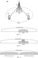
- the communication system 100 can include a network device 110 which can be a device that communicates with terminals 120 (also called communication terminals or terminals).
- the network device 110 can provide communication coverage for a specific geographic area, and can communicate with terminals located in the coverage area.
- the network device 110 can be an Evolutional Node B (eNB or eNodeB) in an LTE system, or a wireless controller in a Cloud Radio Access Network (CRAN), or the network device can be a mobile switching center, a relay station, an access point, an in-vehicle device, a wearable device, a hub, a switch, a bridge, a router, a network side device in a 5G network, a network device in a future communication system, or the like.
- eNB or eNodeB Evolutional Node B
- CRAN Cloud Radio Access Network
- the communication system 100 also includes at least one terminal 120 located within the coverage range of the network device 110.
- the terminal includes, but is not limited to, a device configured to receive/send communication signals and/or an Internet of Things (IoT) device, which may be connected with another device via wired lines, such as Public Switched Telephone Networks (PSTN), Digital Subscriber Line (DSL), digital cables, and direct cable connections; and/or via another data connection/network; and/or via a wireless interface, such as cellular networks, wireless local area networks (WLAN), digital TV networks such as DVB-H networks, satellite networks, AM-FM broadcast transmitter.
- IoT Internet of Things
- a terminal configured to communicate through a wireless interface may be referred to as a "wireless communication terminal", a “wireless terminal” or a “mobile terminal”.
- the mobile terminal include but are not limited to satellite or cellular phones; Personal Communications System (PCS) terminals that can combine cellular radio phones with data processing, fax, and data communication capabilities; PDAs that may include radio phones, pagers, Internet/intranet access, Web browser, memo pad, calendar, and/or Global Positioning System (GPS) receiver; and conventional laptop and/or palmtop receivers or other electronic devices including radio telephone transceivers.
- PCS Personal Communications System
- GPS Global Positioning System
- the terminal device may refer to access terminals, user equipment (UE), user units, user stations, mobile stations, mobile sites, remote stations, remote terminals, mobile equipment, user terminals, terminals, wireless communication equipment, user agents, or user device.
- the access terminal may be a cellular phone, a cordless phone, a Session Initiation Protocol (SIP) phone, a wireless local loop (WLL) station, a personal digital assistant (PDA), and wireless communication functional handheld devices, computing devices or other processing devices connected to wireless modems, in-vehicle devices, wearable devices, terminals in 5G networks, terminals in the future evolution of PLMN, or the like.
- SIP Session Initiation Protocol
- WLL wireless local loop
- PDA personal digital assistant
- D2D communication can be performed between the terminals 120.
- the 5G system or 5G network may also be referred to as a New Radio (NR) system or NR network.
- NR New Radio
- FIG. 1 exemplarily shows one network device and two terminals.
- the communication system 100 may include multiple network devices and other number of terminals can be included in the coverage of each network device, which is not particularly limited in the embodiments of the present disclosure.
- the communication system 100 may also include other network entities such as a network controller and a mobility management entity, which are not limited in the embodiments of the present application.
- network entities such as a network controller and a mobility management entity, which are not limited in the embodiments of the present application.
- the communication device may include a network device 110 and terminals 120 which have the communication function.
- the network device 110 and the terminals 120 may be the specific devices as described above, which will not be repeated here.
- the communication device may also include other devices in the communication system 100, such as a network controller, a mobility management entity, and other network entities, which are not limited in the embodiments of the present disclosure.
- system and “network” are often used interchangeably herein.
- the term “and/or” used herein is merely to describe relative relationships of relative objects, indicating that there can be three kinds of relationships. For example, A and/or B can indicate three cases where A exists alone, A and B exist simultaneously, or B exists alone.
- the character “/” used herein generally indicates that the related objects before and after this character are in an "or” relationship.
- 5G 3rd Generation Partnership Project
- eMBB enhanced Mobile Broadband
- URLLC Ultra-Reliable Low-Latency Communications
- mMTC massive Machine-Type Communications
- eMBB is still targeting at obtaining multimedia content, services and data by the users, and the demand therefor is growing very rapidly.
- eMBB may be deployed in different scenarios, such as indoors, urban areas, rural areas, etc., the capabilities and requirements thereof are also quite different, and they cannot be generalized and must be analyzed in detail in conjunction with specific deployment scenarios.
- Typical applications of URLLC include industrial automation, power automation, telemedicine operations (surgeries), traffic safety protection, etc.
- Typical features of mMTC include high connection density, small data volume, delay insensitive services, low cost and long service life of the module, etc.
- a maximum channel bandwidth can be 400MHZ, known as a wideband carrier. Compared with the maximum bandwidth of 20M in LTE, the bandwidth of the wideband carrier is very large. If the terminal device keeps working on the wideband carrier, the power consumption of the terminal device is very large. Therefore, it is recommended that a radio frequency (RF) bandwidth of the terminal device can be adjusted according to an actual throughput of the terminal device.
- RF radio frequency
- BWP the concept of BWP is introduced, the motivation of which is to optimize the power consumption of terminal device. For example, if a rate of the terminal device is low, the terminal device can be configured with a smaller BWP (as shown in FIG.
- the terminal device can be configured with a larger BWP (as shown in FIG. 2-2 ). If the terminal device supports a high rate or works in a Carrier Aggregation (CA) mode, the terminal device can be configured with a plurality of BWPs (as shown in FIG. 2-3 ). Another purpose of BWP is to trigger coexistence of multiple numerologies in a cell. As shown in FIG. 2-3 , BWP1 corresponds to numerology 1, and BWP2 corresponds to numerology2.
- a terminal can be configured with a maximum of 4 uplink BWPs and a maximum of 4 downlink BWPs, but only one uplink BWP and downlink BWP can be activated at the same time.
- a first activated BWP among the configured BWPs can be indicated in the RRC dedicated signaling.
- switching between different BWPs can also be performed through Downlink Control Information (DCI).
- DCI Downlink Control Information
- the BWP that is activated first is the first activated BWP configured in the RRC dedicated signaling.
- the configuration parameters of each BWP include:
- the terminal When performing Radio Link Monitor (RLM), the terminal performs the RLM only on the active BWP, and it needs not to operate on the inactive BWPs. When switching between different BWPs, there is no need to reset the RLM Related timer and counter. For RRM measurement, no matter on which active BWP the terminal sends and receives data, it does not affect the RRM measurement. Also, the terminal only needs to perform CQI measurement on the active BWP.
- RLM Radio Link Monitor
- an initial BWP that is activated first is the first activated BWP configured in the RRC dedicated signaling.
- a value of the BWP ID in the RRC dedicated signaling ranges from 0 to 4, and the BWP with a BWP ID of 0 is the initial BWP by default.
- CA In order to meet high-speed requirements, CA technology is also supported in 5G.
- CA enables the NR system to support a larger bandwidth by jointly scheduling and using resources on multiple Component Carriers (CCs), thereby enabling a higher system peak rate.
- CCs Component Carriers
- PCC Primary Cell Component
- NAS non-access stratum
- SCC Secondary Cell Component
- the PCC and the SCC are collectively known as serving cells, where the cell on the PCC is a Primary cell (Pcell), and the cell on the SCC is the Scell.
- Pcell Primary cell
- SCC Secondary Cell Component
- the standard also specifies that the aggregated carriers support a maximum of 5 carries, that is, the maximum bandwidth after aggregation is 100MHZ, and the aggregated carriers belong to the same base station.
- C-RNTI Cell-Radio Network Temporary Identifier
- the base station ensures that the C-RNTI does not conflict in the cells where each of the carriers is located. Since both asymmetric carrier aggregation and symmetric carrier aggregation are supported, it is required that the aggregated carriers must have downlink but may not have uplink. And for the PCC cell, there must be the PDCCH and PUCCH of the current cell, and only the primary carrier cell has the PUCCH, and other secondary carrier cells may have the PDCCH.
- PCC cell there must be the PDCCH and PUCCH of the current cell, and only the primary carrier cell has the PUCCH, and other secondary carrier cells may have the PDCCH.
- the Scell is configured through RRC dedicated signaling, and the initial configured state is an inactive state in which data transmission and reception cannot be performed. Then, the data transmission and reception can only be performed if the Scell is activated through the MAC CE. From the perspective of Scell configuration and activation delay, such architecture is not an optimal architecture. And such delay reduces the efficiency of CA usage and radio resources, especially in small cell deployment scenarios. In a dense small cell deployment scenario, the signaling load of each Scell is also very large, especially when each Scell needs to be configured separately. Therefore, the current CA architecture introduces additional delay, which restricts the use of CA and reduces the gain of CA load sharing.
- LTE R15 optimizes the CA, and the functions that are mainly optimized are as follows. 1)
- the states of the Scell include the active state and the inactive state, and in order to realize fast cell recovery, a new cell state is defined, i.e., a dormant state. In the dormant state, the terminal measures and reports CQI/RRM, but does not decode PDCCH.
- a new MAC CE is defined to control the transition between the active state and the dormant state, as shown in FIG. 3-1 and FIG. 3-2 .
- the MAC CE includes 1 byte and controls the state transition of 7 cells, and in FIG.
- the MAC CE includes 4 bytes and controls the state transition of 31 cells, where Ci represents the state corresponding to the cell with an index number of i, and Ci being set to 1 indicates that the cell with the index number of i is in the dormant state, and Ci being set to 0 indicates that the cell with the index number of i is in the active state.
- the state of Scell can be configured to be the active state or the dormant state, and is in the inactive state by default.
- the dormant BWP of the Scell is switched to the non-dormant BWP through the DCI to activate the service transmission function of the cell, which has a shorter activation delay and lower complexity compared with the traditional dormant state of the Scell.
- the state of the Scell is directly configured to be the active state through the RRC, where the active state has a dormancy behavior and a non-dormancy behavior, that is, the dormancy behavior is a part of the active state.
- the Scell state In configuring the Scell state to be the active state through the RRC, there is an issue that needs to be clarified, that is, it needs to be determined whether the state of the Scell is the activated Scell state with the dormancy behavior or the activated Scell state with the non-dormancy behavior.
- the terminal device can stay on the dormant BWP to implement the dormancy behavior, and there is an issue that needs to be clarified, that is, it needs to be determined on which BWP the terminal device stays to send/receive data after switching from the active state with the dormancy behavior to the active state with the non-dormancy behavior.
- the following technical solutions are proposed according to the embodiments of the present application.
- FIG. 4 is a schematic flowchart of a cell state management method provided by an embodiment of the present application. As shown in FIG. 4 , the cell state management method includes the following steps.
- a terminal device receives first configuration information sent by a network device, the first configuration information being used to indicate whether a state of a first cell is a first state or a second state, wherein the first state represents an active state with a dormancy behavior, and the second state represents an active state with a non-dormancy behavior.
- the network device sends the first configuration information to the terminal device, and accordingly, the terminal device receives the first configuration information sent by the network device.
- the network device may be a base station, such as a gNB.
- the first configuration information is carried in RRC signaling.
- the first configuration information includes uplink BWP configuration information and downlink BWP configuration information
- the uplink BWP configuration information includes at least one uplink BWP configuration
- the downlink BWP configuration information includes at least one downlink BWP configuration
- the uplink BWP configuration information carries first indication information, and the first indication information is used to indicate a BWP identification corresponding to an uplink initial activated BWP; the downlink BWP configuration information carries second indication information, and the second indication information is used to indicate the BWP identification corresponding to a downlink initial activated BWP; and the initial activated BWP represents a BWP that is first activated.
- the uplink BWP configuration information includes a number of N1 uplink BWP configurations, where N1 is a positive integer, and further, N1 is an integer greater than or equal to 1 and less than or equal to 4.
- the downlink BWP configuration information includes a number of N2 downlink BWP configurations, where N2 is a positive integer, and further, N2 is an integer greater than or equal to 1 and less than or equal to 4.
- the uplink BWP and the downlink BWP are independently configured.
- the network device separately indicates the initial activated BWP in the uplink BWP configuration information and the downlink BWP configuration information, where the initial activated BWP refers to the BWP that is first activated.
- the network device indicates the BWP identification corresponding to the uplink initial activated BWP by carrying the first indication information in the uplink BWP configuration information.
- the network device indicates the BWP identification corresponding to the downlink initial activated BWP by carrying the first indication information in the downlink BWP configuration information.
- the uplink BWP configuration information further carries third indication information
- the downlink BWP configuration information carries fourth indication information
- the third indication information is used to indicate the BWP identification corresponding to an uplink dormant BWP
- the fourth indication information is used to indicate the BWP identification corresponding to a downlink dormant BWP.
- the first cell is a Scell
- the active state of the Scell may also be referred to as an activated SCell state.
- the dormancy behavior (corresponding to the first state) or non-dormancy behavior (corresponding to the second state) of the activated SCell state is configured through the RRC signaling.
- the first state refers to an activated state with a dormancy behavior, i.e., an activated dormancy state
- the second state refers to an activated state with a non-dormancy behavior, i.e., an activated non-dormancy state.
- the configuration of the first state and the second state may be specifically implemented in any of the following ways.
- the state of the SCell is configured to be the first state (i.e., the activated dormancy state) or the second state (i.e., the activated non-dormancy state) through the RRC signaling, as shown in Table 2-1 below, where sCellState represents the fifth indication information.
- the terminal device ignores the first indication information and/or the second indication information, and remains to stay on the dormant BWP.
- the first indication information indicates the BWP identification corresponding to the uplink initial activated BWP (i.e., firstActiveDownlinkBWP-Id)
- the second indication information indicates the BWP identification corresponding to the downlink initial activated BWP (i.e., firstActiveUplinkBWP-Id).
- the BWP identification indicated by the first indication information and/or the second indication information is different from the BWP identification of the dormant BWP. That is, "firstActiveDownlinkBWP-Id" and/or “firstActiveUplinkBWP-Id" cannot be set to the BWP identification corresponding to the dormant BWP.
- the first configuration information carries fifth indication information and sixth indication information, the fifth indication information is used to indicate that the state of the first cell is the active state, and the sixth indication information is used to indicate that a type of the active state is dormancy or non-dormancy; wherein the type of the activation state being the dormancy indicates that the state of the first cell is the first state, and the type of the activation state being the non-dormancy indicates the state of the first cell is the second state.
- the state of the SCell is configured as the active state through the RRC signaling, and it also indicates whether the type of the active state of the Scell is dormancy (corresponding to the first state) or non-dormancy (corresponding to the second state), as shown in Table 2-2 below, where SCellState represents the fifth indication information, and sCellStateType represents the sixth indication information.
- the terminal device ignores the first indication information and/or the second indication information, and remains to stay on the dormant BWP.
- the first indication information indicates the BWP identification corresponding to the uplink initial activated BWP (i.e., firstActiveDownlinkBWP-Id)
- the second indication information indicates the BWP identification corresponding to the downlink initial activated BWP (i.e., firstActiveUplinkBWP-Id).
- the BWP identification indicated by the first indication information and/or the second indication information is different from the BWP identification of the dormant BWP. That is, "firstActiveDownlinkBWP-Id" and/or “firstActiveUplinkBWP-Id" cannot be set to the BWP identification corresponding to the dormant BWP.
- the first configuration information carries fifth indication information, and the fifth indication information is used to indicate that the state of the first cell is the active state; if the BWP identification indicated by the first indication information and/or the second indication information is the same as the BWP identification of the dormant BWP, an initial state of the first cell is the first state; and if the BWP identification indicated by the first indication information and/or the second indication information is different from the BWP identification of the dormant BWP, the initial state of the first cell is the second state.
- the state of ScellState is set to the active state, and "firstActiveDownlinkBWP-Id" and/or “firstActiveUplinkBWP-Id” is set to the BWP identification corresponding to the dormant BWP, indicating that the initial SCell state is the activated dormancy state; otherwise, the initial SCell state is the activated non-dormancy state.
- a bandwidth of the dormant BWP is included in a first BWP indicated by the first configuration information; or the bandwidth of the dormant BWP partially overlaps the bandwidth of the first BWP indicated by the first configuration information.
- the first BWP is an uplink initial activated BWP and/or a downlink initial activated BWP; or the first BWP is a (arbitrary) non-dormant BWP.
- the dormant BWP is not assigned a corresponding BWP identification, so that the use of the BWP identification can be saved.
- the dormant BWP is configured at a cell granularity; and, not according to the invention, the configuration of the dormant BWP is carried in a system broadcast message of the first cell.
- the network side can control the BWP state transition through DCI, which will be described in detail below.
- the network device sends first control signaling to the terminal device, and after receiving the first control signaling sent by the network device, the terminal device switches from the current BWP to a first BWP, where the first control signaling is used to instruct the terminal device to enter the second state from the first state.
- the first control signaling is layer 1 (L1) signaling, such as DCI.
- L1 layer 1
- the terminal device autonomously switches to the first BWP configured by the RRC signaling.
- the first BWP may be any of the following. 1)
- the first BWP is the uplink initial activated BWP (i.e., firstActiveDownlinkBWP) and/or the downlink initial activated BWP (i.e., firstActiveUplinkBWP) that is configured in the first configuration information.
- the first BWP is an uplink BWP and/or a downlink BWP that last serves before the terminal device enters the first state.
- the first BWP is a BWP after the terminal device enters the second state that is indicated in the first control signaling (such as DCI).
- the network side needs to explicitly indicate the activated BWP after the terminal device enters the activated non-dormancy state through DCI.
- the network side can control the Scell state transition through the MAC CE, which will be described in detail below.
- the second control signaling is a MAC CE.
- a terminal device when a terminal device receives a MAC CE used for indicating SCell activation/deactivation (i.e., a SCell Activation/Deactivation MAC CE), as for the SCell that is indicated to enter the inactive state from the active state, the terminal device considers that it enters the inactive state regardless of whether the activated dormancy state or activated non-dormancy state is indicated. It should be noted that the inactive state in the embodiments of the present application may also be referred to as a deactivated state.
- the network device sends third control signaling to the terminal device, and the terminal device enters the second state from the inactive state after receiving the third control signaling sent by the network device, where the third control signaling is used to instruct the terminal device to enter the active state from the inactive state or to enter the second state from the inactive state.
- the third control signaling is a MAC CE.
- the terminal device considers that the Scell will always enters the activated non-dormancy state (that is, the second state).
- the third control signaling is a MAC CE.
- whether the initial behavior of the Scell entering the active state is dormancy or non-dormancy is configured through the RRC signaling.
- the terminal device enters the active state from the inactive state, it enters the activated dormancy state or activated non-dormancy state that is configured by the RRC signaling.
- the first cell group may also be referred to as a PUCCH group, and uplink control information (such as feedback information) of all Scells included in the PUCCH group is transmitted through a PUCCH Scell, where the PUCCH Scell is one of the Scells in the PUCCH group.
- uplink control information such as feedback information
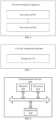
- FIG. 6 is a first schematic diagram of structural composition of a cell state management device apparatus provided by an embodiment of the application, which is applied to a terminal device.
- the cell state management apparatus includes: a receiving unit 601 configured to receive first configuration information sent by a network device, the first configuration information being used to indicate whether a state of a first cell is a first state or a second state, where the first state represents an active state with a dormancy behavior, and the second state represents an active state with a non-dormancy behavior.
- the first configuration information includes uplink BWP configuration information and downlink BWP configuration information
- the uplink BWP configuration information includes at least one uplink BWP configuration
- the downlink BWP configuration information includes at least one downlink BWP configuration
- the uplink BWP configuration information carries first indication information, and the first indication information is used to indicate a BWP identification corresponding to an uplink initial activated BWP; the downlink BWP configuration information carries second indication information, and the second indication information is used to indicate the BWP identification corresponding to a downlink initial activated BWP; and the initial activated BWP represents a BWP that is first activated.
- the uplink BWP configuration information further carries third indication information
- the downlink BWP configuration information carries fourth indication information
- the third indication information is used to indicate the BWP identification corresponding to an uplink dormant BWP
- the fourth indication information is used to indicate the BWP identification corresponding to a downlink dormant BWP.
- the first configuration information carries fifth indication information, and the fifth indication information is used to indicate that the state of the first cell is the first state or the second state.
- the first configuration information carries fifth indication information and sixth indication information
- the fifth indication information is used to indicate that the state of the first cell is the active state
- the sixth indication information is used to indicate a type of the active state is dormancy or non-dormancy; where the type of the active state being the dormancy indicates that the state of the first cell is the first state, and the type of the active state being the non-dormancy indicates that the state of the first cell is the second state.
- the terminal device ignores the first indication information and/or the second instruction information, and remains to stay on the dormant BWP.
- the BWP identification indicated by the first indication information and/or the second indication information is different from the BWP identification of the dormant BWP.
- the first configuration information carries fifth indication information, and the fifth indication information is used to indicate that the state of the first cell is the active state.
- an initial state of the first cell is the first state; and if the BWP identification indicated by the first indication information and/or the second indication information is different from the BWP identification of the dormant BWP, the initial state of the first cell is the second state.
- a bandwidth of the dormant BWP is included in a first BWP indicated in the first configuration information; or the bandwidth of the dormant BWP partially overlaps the bandwidth of the first BWP indicated in the first configuration information.
- the first BWP is an uplink initial activated BWP and/or a downlink initial activated BWP; or the first BWP is a non-dormant BWP.
- the dormant BWP is not assigned a corresponding BWP identification; or the dormant BWP is assigned a corresponding BWP identification, and the BWP identification is greater than or equal to N, where N is a positive integer.
- the dormant BWP is configured at a cell granularity; and not according to the invention, the configuration of the dormant BWP is carried in a system broadcast message of the first cell.
- the first configuration information is carried in RRC signaling.
- the receiving unit 601 is further configured to receive first control signaling sent by the network device; and the apparatus further includes a processing unit 602, configured to switch from a current BWP to a first BWP, and the first control signaling is used to instruct the terminal device to enter the second state from the first state .
- the first BWP is an uplink initial activated BWP and/or a downlink initial activated BWP that is configured in the first configuration information.
- the first BWP is an uplink BWP and/or a downlink BWP that last serves before the terminal device enters the first state.
- the first BWP is a BWP after the terminal device enters the second state that is indicated in the first control signaling.
- the first control signaling is DCI.
- the receiving unit 601 is further configured to receive second control signaling sent by the network device.
- the second control signaling is a MAC CE.
- the receiving unit 601 is further configured to receive third control signaling sent by the network device;
- the receiving unit 601 is further configured to receive third control signaling sent by the network device;
- the third control signaling is a MAC CE.
- the first cell is a Scell.
- the first cell is a PScell in an SCG
- the first cell is a PUCCH Scell in a first cell group
- FIG. 7 is a second schematic diagram of structural composition of a cell state management apparatus provided by an embodiment of the application, which is applied to a network device.
- the cell state management apparatus includes: a sending unit 701 configured to send first configuration information to a terminal device, the first configuration information being used to indicate whether a state of a first cell is a first state or a second state, where the first state represents an active state with a dormancy behavior, and the second state represents an active state with a non-dormancy behavior.
- the first configuration information includes uplink BWP configuration information and downlink BWP configuration information
- the uplink BWP configuration information includes at least one uplink BWP configuration
- the downlink BWP configuration information includes at least one downlink BWP configuration
- the uplink BWP configuration information carries first indication information, and the first indication information is used to indicate a BWP identification corresponding to an uplink initial activated BWP; the downlink BWP configuration information carries second indication information, and the second indication information is used to indicate the BWP identification corresponding to a downlink initial activated BWP; and the initial activated BWP represents a BWP that is first activated.
- the uplink BWP configuration information further carries third indication information
- the downlink BWP configuration information carries fourth indication information
- the third indication information is used to indicate the BWP identification corresponding to an uplink dormant BWP
- the fourth indication information is used to indicate the BWP identification corresponding to a downlink dormant BWP.
- the first configuration information carries fifth indication information, and the fifth indication information is used to indicate that the state of the first cell is the first state or the second state.
- the first configuration information carries fifth indication information and sixth indication information
- the fifth indication information is used to indicate that the state of the first cell is the active state
- the sixth indication information is used to indicate that a type of the active state is dormancy or non-dormancy; where the type of the active state being the dormancy indicates that the state of the first cell is the first state, and the type of the active state being the non-dormancy indicates that the state of the first cell is the second state.
- the first configuration information carries fifth indication information, and the fifth indication information is used to indicate that the state of the first cell is the active state;
- a bandwidth of the dormant BWP is included in a first BWP indicated in the first configuration information; or the bandwidth of the dormant BWP partially overlaps the bandwidth of the first BWP indicated in the first configuration information.
- the first BWP is an uplink initial activated BWP and/or a downlink initial activated BWP; or the first BWP is a non-dormant BWP.
- the dormant BWP is not assigned a corresponding BWP identification; or the dormant BWP is assigned a corresponding BWP identification, and the BWP identification is greater than or equal to N, where N is a positive integer.
- the dormant BWP is configured at a cell granularity; and not according to the invention, the configuration of the dormant BWP is carried in a system broadcast message of the first cell.
- the first configuration information is carried in RRC signaling.
- the sending unit 701 is further configured to send first control signaling to the terminal device to trigger the terminal device to switch from the current BWP to a first BWP; where the control signaling is used to instruct the terminal device to enter the second state from the first state.
- the first BWP is an uplink initial activated BWP and/or a downlink initial activated BWP configured in the first configuration information.
- the first BWP is an uplink BWP and/or a downlink BWP that last serves before the terminal device enters the first state.
- the first BWP is a BWP after the terminal device enters the second state that is indicated in the first control signaling.
- the first control signaling is DCI.
- the sending unit 701 is further configured to send second control signaling to the terminal device to trigger the terminal device to enter an inactive state from the first state or the second state.
- the second control signaling is used to instruct the terminal device to enter the inactive state from the active state, to enter the inactive state from the first state, or to enter the inactive state from the second state.
- the second control signaling is a MAC CE.
- the sending unit 701 is further configured to send third control signaling to the terminal device to trigger the terminal device to enter the second state from the inactive state. where the third control signaling is used to instruct the terminal device to enter the active state from the inactive state or to enter the second state from the inactive state.
- the sending unit 701 is further configured to send third control signaling to the terminal device to trigger the terminal device to enter a target state from the inactive state, the target state is determined based on the seventh indication information in the first configuration information, and the seventh indication information is used to indicate that an initial state of the first cell when the first cell enters the active state is the first state or the second state.
- the third control signaling is used to instruct the terminal device to enter the active state from the inactive state, to enter the first state from the inactive state, or to enter the second state from the inactive state.
- the third control signaling is a MAC CE.
- the first cell is a Scell.
- the first cell is a PScell in an SCG
- the first cell is a PUCCH Scell in a first cell group
- FIG. 8 is a schematic structural diagram of a communication device 800 according to an embodiment of the present application.
- the communication device can be a terminal device or a network device.
- the communication device 800 shown in FIG. 8 includes a processor 810 which can invoke and execute a computer program from a memory to carry out the methods in the embodiments of the present application.
- the communication device 800 can further include a memory 820.
- the processor 810 can call and run the computer program from the memory 820 to carry out the methods in the embodiments of the present application.
- the memory 820 can be a separate device independent of the processor 810, or can be integrated in the processor 810.
- the communication device 800 can further include a transceiver 830, and the processor 810 can control the transceiver 830 to communicate with other devices, and specifically to transmit information or data to other devices, or receive information or data transmitted from other devices.
- the transceiver 830 can include a transmitter and a receiver.
- the transceiver 830 can further include an antenna, and the number of the antennas can be one or more.
- the communication device 800 can specifically be a network device in the embodiments of the present application, and the communication device 800 can carry out the corresponding processes which are implemented by the network device in the methods of the embodiments of the present application, which will not be repeated here for the sake of brevity.
- the communication device 800 can specifically be a mobile terminal/terminal device in the embodiments of the application, and the communication device 800 can implement the corresponding processes which are implemented by the mobile terminal/terminal device in the methods according to the embodiments of the present application, which will not be repeated here for the sake of brevity.
- FIG. 9 is a schematic structural diagram of a chip according to an embodiment of the present application.
- the chip 900 shown in FIG. 9 includes a processor 910 which can invoke and run a computer program from a memory to implement the methods in the embodiments of the present application.
- the chip 900 can further include a memory 920.
- the processor 910 can invoke and run the computer program from the memory 920 to implement the methods in the embodiments of the present application.
- the memory 920 can be a separate device independent of the processor 910, or can be integrated in the processor 910.
- the chip 900 can further include an input interface 930.
- the processor 910 can control the input interface 930 to communicate with other devices or chips, and particularly to obtain information or data transmitted by other devices or chips.
- the chip 900 can further include an output interface 940.
- the processor 910 can control the output interface 940 to communicate with other devices or chips, and particularly to output information or data to other devices or chips.
- the chip can be applied to the network device in the embodiments of the present application, and the chip can carry out the corresponding processes which are implemented by the network device in the methods of the embodiments of the present application, which will not be repeated here for the sake of brevity.
- the chip can be applied to the mobile terminal/terminal device in the embodiments of the present application, and the chip can implement the corresponding processes which are implemented by the mobile terminal/terminal device in the methods of the embodiments of the present application, which will not be repeated here for the sake of brevity.
- the chip mentioned in the embodiments of the present application can also be referred to as a system-level chip, a system chip, a chip system, or a system-on-chip.
- FIG. 10 is a schematic block diagram of a communication system 1000 according to an embodiment of the present application. As shown in FIG. 10 , the communication system 1000 includes a terminal device 1010 and a network device 1020.
- the terminal device 1010 can be used to implement the corresponding functions implemented by the terminal device in the above methods, and the network device 1020 can be used to implement the corresponding functions implemented by the network device in the above methods, which will not be repeated here for the sake of brevity.
- the processor can be an integrated circuit chip with signal processing capability.
- the steps of the foregoing method embodiments can be performed by an integrated logic circuit of hardware in the processor or by instructions in a form of software.
- the foregoing processor can be a general-purpose processor, a Digital Signal Processor (DSP), an Application Specific Integrated Circuit (ASIC), a Field Programmable Gate Array (FPGA), other programmable logic devices, discrete gate or transistor logic device, or a discrete hardware component, which can implement the methods, steps, and logical blocks disclosed in the embodiments of the present disclosure.
- the general-purpose processor can be a microprocessor, any conventional processor or the like.
- the steps of the methods disclosed in connection with the embodiments of the present disclosure can be directly embodied in and performed by a hardware decoding processor, or can be implemented by a combination of hardware and software modules in the decoding processor.
- the software modules can be located in a mature storage medium in the art such as a random access memory, a flash memory, a read-only memory, a programmable read-only memory, an electrically erasable programmable memory or a register.
- the storage medium is located in the memory, and the processor reads information in the memory and implements the steps of the above methods in combination with the hardware thereof.
- the memory in the embodiments of the present application may be a volatile memory or a non-volatile memory, or may include both the volatile and non-volatile memories.
- the non-volatile memory can be a Read-Only Memory (ROM), a Programmable ROM (PROM), an erasable PROM (EPROM), an electrically EPROM (EEPROM) or a flash memory.
- the volatile memory may be a Random Access Memory (RAM), which is used as an external cache.
- RAMs such as a Static RAM (SRAM), a Dynamic RAM (DRAM), a Synchronous DRAM (SDRAM), a Double Data Rate SDRAM (DDR SDRAM), an Enhanced SDRAM (ESDRAM), a Synchlink DRAM (SLDRAM) ) and a Direct Rambus RAM (DR RAM).
- SRAM Static RAM
- DRAM Dynamic RAM
- SDRAM Synchronous DRAM
- DDR SDRAM Double Data Rate SDRAM
- ESDRAM Enhanced SDRAM
- SLDRAM Synchlink DRAM
- DR RAM Direct Rambus RAM
- the memory in the embodiments of the present disclosure can also be a Static RAM (SRAM), a Dynamic RAM (DRAM), a Synchronous DRAM (SDRAM), a Double Data Rate SDRAM (DDR SDRAM), an Enhanced SDRAM (ESDRAM), a Synch-Link DRAM (SLDRAM), a Direct Rambus RAM (DR RAM), among others. That is to say, the memory in the embodiments of the present disclosure is intended to include but is not limited to those and any other suitable types of memories.
- SRAM Static RAM
- DRAM Dynamic RAM
- SDRAM Synchronous DRAM
- DDR SDRAM Double Data Rate SDRAM
- ESDRAM Enhanced SDRAM
- SLDRAM Synch-Link DRAM
- DR RAM Direct Rambus RAM
- the embodiments of the present application also provide a computer-readable storage medium for storing a computer program.
- the computer-readable storage medium can be applied to the network device in the embodiments of the present application, and the computer program causes a computer to perform the corresponding processes which are implemented by the network device in the methods of the embodiments of the present application, which will not be repeated here for the sake of brevity.
- the computer-readable storage medium can be applied to the mobile terminal/terminal device in the embodiments of the present application, and the computer program causes a computer to perform the corresponding processes which are implemented by the mobile terminal/terminal device in the methods of the embodiments of the present application, which will not be repeated here for the sake of brevity.
- the embodiments of the present application also provide a computer program product including computer program instructions.
- the computer program product can be applied to the network device in the embodiments of the present application, and the computer program instructions cause a computer to perform the corresponding processes implemented by the network device in the methods according to the embodiments of the present application, which will not be repeated here for the sake of brevity.
- the computer program product can be applied to the mobile terminal/terminal device in the embodiments of the present application, and the computer program instructions cause a computer to perform the corresponding processes which are implemented by the mobile terminal/terminal device in the methods of the embodiments of the present application, which will not be repeated here for the sake of brevity.
- the embodiments of the application also provide a computer program.
- the computer program can be applied to the network device in the embodiments of the present application, and when running on a computer, the computer program causes the computer to perform the corresponding process implemented by the network device in the methods according to the embodiments of the present application, which will not be repeated here for the sake of brevity.
- the computer program can be applied to the mobile terminal/terminal device in the embodiments of the present application, and when running on a computer, the computer program causes the computer to perform the corresponding processes implemented by the mobile terminal/terminal device in the methods of the embodiments of the present application, which will not be repeated here for the sake of brevity.
- the systems, devices, and methods disclosed in several embodiments of the present disclosure can be implemented in other manners.
- the device embodiments described above are merely illustrative.
- the division of the units is only a logical function division, and in actual implementations, there can be other division manners.
- a plurality of units or components can be combined or integrated into another system, or some features can be ignored or not implemented.
- the coupling or direct coupling or communication connection shown or discussed herein can also be indirect coupling or communication connection through some interfaces, devices or units, and can be in electrical, mechanical or other forms.
- the units described as separate components may be or may not be physically separated, and the components shown as units may be or may not be physical units, that is, they may be located in one place or may be distributed on multiple network units. Some or all of the units can be selected to achieve the objectives of the solutions of the embodiments according to actual requirements.
- the functional units in the embodiments of the present disclosure can be integrated into one processing unit, or each unit can individually exist physically, or two or more of the units can be integrated into one unit.
- the functions can be stored in a computer-readable storage medium.
- the technical solution of the present disclosure essentially, a part thereof that contributes to the prior art, or a part of the technical solution can be embodied in the form of a software product, and the computer software product is stored in a storage medium and includes instructions which enable a computer device (which may be a personal computer, a server, a network device or the like) to perform all or part of the steps of the methods described in the embodiments of the present disclosure.
- the foregoing storage medium includes various medium such as a USB drive, a removable hard disk, a ROM, a RAM, a magnetic disk or an optical disc that can store program codes.
Landscapes
- Engineering & Computer Science (AREA)
- Signal Processing (AREA)
- Computer Networks & Wireless Communication (AREA)
- Computer Security & Cryptography (AREA)
- Multimedia (AREA)
- Mobile Radio Communication Systems (AREA)
- Telephonic Communication Services (AREA)
- Data Exchanges In Wide-Area Networks (AREA)
Claims (13)
- Verfahren zur Zellzustandsverwaltung, umfassend:
Empfangen (401), durch eine Endgerätevorrichtung, von ersten Konfigurationsinformationen, die durch eine Netzwerkvorrichtung gesendet werden, wobei die ersten Konfigurationsinformationen in der Radio Resource Control-, RRC-, Signalisierung getragen werden und verwendet werden, um anzugeben, ob ein Zustand einer ersten Zelle ein erster Zustand oder ein zweiter Zustand ist, wobei der erste Zustand einen aktiven Zustand mit einem Ruhezustandsverhalten darstellt und der zweite Zustand einen aktiven Zustand mit einem Nicht-Ruhezustandsverhalten darstellt, wobei die ersten Konfigurationsinformationen ferner umfassen:
Uplink-Bandbreitenteil-, BWP-, Konfigurationsinformationen und Downlink-BWP-Konfigurationsinformationen, wobei:die Uplink-BWP-Konfigurationsinformationen mindestens eine Uplink-BWP-Konfiguration umfassen, wobei die Uplink-BWP-Konfigurationsinformationen erste Angabeinformationen tragen, wobei die ersten Angabeinformationen verwendet werden, um eine BWP-Identifikation anzugeben, die einem anfänglich aktivierten Uplink-BWP entspricht;die Downlink-BWP-Konfigurationsinformationen mindestens eine Downlink-BWP-Konfiguration umfasst, wobei die Downlink-BWP-Konfigurationsinformationen zweite Angabeinformationen und vierte Angabeinformationen tragen, wobei die zweiten Angabeinformationen verwendet werden, um die BWP-Identifikation anzugeben, die einem anfänglich aktivierten Downlink-BWP entspricht, und die vierten Angabeinformationen verwendet werden, um eine BWP-Identifikation anzugeben, die einem ruhenden Downlink-BWP entspricht; undder anfänglich aktivierte BWP einen BWP repräsentiert, der zuerst aktiviert wird. - Verfahren nach Anspruch 1, wobei die Uplink-BWP-Konfigurationsinformationen ferner dritte Angabeinformationen tragen, wobei die dritten Angabeinformationen dazu verwendet werden, eine BWP-Identifikation anzugeben, die einem ruhenden Uplink-BWP entspricht.
- Verfahren nach Anspruch 1 oder 2, wobei die ersten Konfigurationsinformationen fünfte Angabeinformationen tragen und die fünften Angabeinformationen verwendet werden, um anzugeben, dass der Zustand der ersten Zelle der erste Zustand oder der zweite Zustand ist;wenn die durch die ersten Angabeinformationen und/oder die zweiten Angabeinformationen angegebene BWP-Identifikation dieselbe ist wie eine BWP-Identifikation einer entsprechenden ruhenden Uplink- und/oder Downlink-BWP, ein anfänglicher Zustand der ersten Zelle der erste Zustand ist; undwenn die durch die ersten Angabeinformationen und/oder die zweiten Angabeinformationen angegebene BWP-Identifikation von der BWP-Identifikation einer entsprechenden ruhenden Uplink- und/oder Downlink-BWP unterschiedlich ist, der anfängliche Zustand der ersten Zelle der zweite Zustand ist.
- Verfahren nach einem der Ansprüche 1 bis 3, ferner umfassend:
Umschalten durch die Endgerätevorrichtung nach Empfangen einer ersten, von der Netzwerkvorrichtung gesendeten Steuersignalisierung von einem aktuellen BWP in einen ersten BWP, wobei die erste Steuersignalisierung verwendet wird, um die Endgerätevorrichtung anzuweisen, vom ersten Zustand in den zweiten Zustand einzutreten. - Verfahren nach Anspruch 4, wobei der erste BWP ein anfänglich aktivierter Uplink-BWP und/oder ein anfänglich aktivierter Downlink-BWP ist, der in den ersten Konfigurationsinformationen ausgelegt ist, oder wobei der erste BWP ein Uplink-BWP und/oder ein Downlink-BWP ist, der zuletzt dient, bevor die Endgerätevorrichtung in den ersten Zustand eintritt.
- Verfahren nach Anspruch 4 oder 5, wobei die erste Steuersignalisierung DCI ist.
- Verfahren nach einem der Ansprüche 1 bis 6, ferner umfassend:
Eintreten durch die Endgerätevorrichtung nach dem Empfangen einer zweiten, von der Netzwerkvorrichtung gesendeten Steuersignalisierung in einen inaktiven Zustand aus dem ersten Zustand oder dem zweiten Zustand; wobei die zweite Steuersignalisierung verwendet wird, um die Endgerätevorrichtung anzuweisen, aus dem ersten Zustand in den inaktiven Zustand einzutreten, oder aus dem zweiten Zustand in den inaktiven Zustand einzutreten. - Verfahren nach Anspruch 7, wobei die zweite Steuersignalisierung ein MAC CE ist.
- Verfahren zur Zellzustandsverwaltung, umfassend:
Senden, durch eine Netzwerkvorrichtung, von ersten Konfigurationsinformationen, an eine Endgerätevorrichtung, wobei die ersten Konfigurationsinformationen in der Radio Resource Control-, RRC-, Signalisierung getragen werden und verwendet werden, um anzugeben, ob ein Zustand einer ersten Zelle ein erster Zustand oder ein zweiter Zustand ist, wobei der erste Zustand einen aktiven Zustand mit einem Ruhezustandsverhalten darstellt und der zweite Zustand einen aktiven Zustand mit einem Nicht-Ruhezustandsverhalten darstellt, wobei die ersten Konfigurationsinformationen ferner umfassen:
Uplink-Bandbreitenteil-, BWP-, Konfigurationsinformationen und Downlink-BWP-Konfigurationsinformationen, wobei:die Uplink-BWP-Konfigurationsinformationen mindestens eine Uplink-BWP-Konfiguration umfassen, wobei die Uplink-BWP-Konfigurationsinformationen erste Angabeinformationen tragen, wobei die ersten Angabeinformationen verwendet werden, um eine BWP-Identifikation anzugeben, die einem anfänglich aktivierten Uplink-BWP entspricht;die Downlink-BWP-Konfigurationsinformationen mindestens eine Downlink-BWP-Konfiguration umfasst, wobei die Downlink-BWP-Konfigurationsinformationen zweite Angabeinformationen und vierte Angabeinformationen tragen, wobei die zweiten Angabeinformationen verwendet werden, um die BWP-Identifikation anzugeben, die einem anfänglich aktivierten Downlink-BWP entspricht, und die vierten Angabeinformationen verwendet werden, um eine BWP-Identifikation anzugeben, die einem ruhenden Downlink-BWP entspricht; undder anfänglich aktivierte BWP einen BWP repräsentiert, der zuerst aktiviert wird. - Verfahren zur Zellstatusverwaltung nach Anspruch 9, ferner umfassend:Senden einer dritten Steuersignalisierung durch die Netzwerkvorrichtung an die Endgerätevorrichtung, um die Endgerätevorrichtung zu triggern, aus einem inaktiven Zustand in einen Zielzustand einzutreten, wobei der Zielzustand basierend auf siebten Angabeinformationen in den ersten Konfigurationsinformationen bestimmt wird und die siebten Angabeinformationen verwendet werden, um anzugeben, dass ein anfänglicher Zustand der ersten Zelle, wenn die erste Zelle in den aktiven Zustand mit Ruhezustands- oder Nicht-Ruhezustandsverhalten eintritt, der erste Zustand bzw. der zweite Zustand ist;wobei die dritte Steuersignalisierung verwendet wird, um die Endgerätevorrichtung anzuweisen, aus dem inaktiven Zustand in den ersten Zustand einzutreten oder aus dem inaktiven Zustand in den zweiten Zustand einzutreten,wobei die dritte Steuersignalisierung ein MAC CE ist.
- Verfahren nach Anspruch 9 oder 10, wobei die erste Zelle eine S-Zelle ist.
- Vorrichtung zur Zellzustandsverwaltung, die auf eine Endgerätevorrichtung angewendet wird, wobei die Vorrichtung dazu ausgelegt ist, das Verfahren nach einem der Ansprüche 1 bis 8 durchzuführen.
- Vorrichtung zur Zellzustandsverwaltung, die auf eine Netzwerkvorrichtung angewendet wird, wobei die Vorrichtung dazu ausgelegt ist, das Verfahren nach einem der Ansprüche 9 bis 11 durchzuführen.
Applications Claiming Priority (1)
| Application Number | Priority Date | Filing Date | Title |
|---|---|---|---|
| PCT/CN2019/115395 WO2021087678A1 (zh) | 2019-11-04 | 2019-11-04 | 一种小区状态管理方法及装置、终端设备、网络设备 |
Publications (3)
| Publication Number | Publication Date |
|---|---|
| EP3886528A1 EP3886528A1 (de) | 2021-09-29 |
| EP3886528A4 EP3886528A4 (de) | 2022-03-09 |
| EP3886528B1 true EP3886528B1 (de) | 2023-06-07 |
Family
ID=75848717
Family Applications (1)
| Application Number | Title | Priority Date | Filing Date |
|---|---|---|---|
| EP19951253.4A Active EP3886528B1 (de) | 2019-11-04 | 2019-11-04 | Verfahren und vorrichtungen zur zellenzustandsverwaltung |
Country Status (6)
| Country | Link |
|---|---|
| US (2) | US11317464B2 (de) |
| EP (1) | EP3886528B1 (de) |
| KR (1) | KR20220092451A (de) |
| CN (2) | CN113517970B (de) |
| ES (1) | ES2949633T3 (de) |
| WO (1) | WO2021087678A1 (de) |
Families Citing this family (9)
| Publication number | Priority date | Publication date | Assignee | Title |
|---|---|---|---|---|
| WO2021087678A1 (zh) * | 2019-11-04 | 2021-05-14 | Oppo广东移动通信有限公司 | 一种小区状态管理方法及装置、终端设备、网络设备 |
| CN112788759A (zh) * | 2019-11-08 | 2021-05-11 | 华为技术有限公司 | 一种通信方法及装置 |
| EP4320926A4 (de) * | 2021-05-07 | 2025-02-19 | Samsung Electronics Co., Ltd. | Verfahren und vorrichtung zur unterstützung der systeminformationserfassung durch ein sidelink-fernendgerät über ein sidelink-relais |
| CN117693969A (zh) * | 2021-08-16 | 2024-03-12 | Oppo广东移动通信有限公司 | 关闭小区的方法、终端设备、网络设备及存储介质 |
| EP4417000A4 (de) * | 2021-10-15 | 2025-09-03 | Lg Electronics Inc | Verfahren und vorrichtung zur verbindungsüberwachung in einem drahtlosen kommunikationssystem |
| CN118044252A (zh) * | 2021-11-19 | 2024-05-14 | Oppo广东移动通信有限公司 | 无线通信方法,终端设备及网络设备 |
| CN119325734A (zh) | 2022-08-11 | 2025-01-17 | 中兴通讯股份有限公司 | 用于节约网络能量的方法 |
| CN119923824A (zh) * | 2022-09-28 | 2025-05-02 | 富士通株式会社 | 信息处理方法和装置 |
| CN115997457A (zh) * | 2022-11-28 | 2023-04-21 | 北京小米移动软件有限公司 | 一种传输信息的方法、装置、设备及可读存储介质 |
Family Cites Families (12)
| Publication number | Priority date | Publication date | Assignee | Title |
|---|---|---|---|---|
| KR101084844B1 (ko) * | 2007-02-06 | 2011-11-21 | 노키아 코포레이션 | 효율적인 불연속 통신을 제공하는 방법 및 장치 |
| CN103338500A (zh) * | 2012-12-24 | 2013-10-02 | 上海华为技术有限公司 | 一种数据传输方法、装置、系统及网络侧设备和终端设备 |
| US20150327156A1 (en) * | 2014-05-06 | 2015-11-12 | Qualcomm Incorporated | Optimization of mbsfn decoding on scells when the pcell and scells belong to same mbsfn area |
| CN109586881B (zh) * | 2017-09-29 | 2021-11-12 | 株式会社Kt | 用于在新无线电中切换带宽部分的方法和装置 |
| US11133912B2 (en) * | 2017-10-02 | 2021-09-28 | Qualcomm Incorporated | Bandwidth part activation, deactivation, and switching in wireless communications |
| US11576085B2 (en) * | 2017-10-25 | 2023-02-07 | Qualcomm Incorporated | Secondary cell activation and deactivation enhancements in new radio |
| CN110012556B (zh) * | 2018-01-04 | 2021-06-15 | 维沃移动通信有限公司 | 一种状态转换处理方法及相关设备 |
| CN110351854B (zh) * | 2018-04-04 | 2021-08-20 | 华为技术有限公司 | 配置信息指示方法及通信装置 |
| US11375518B2 (en) * | 2019-01-23 | 2022-06-28 | Samsung Electronics Co., Ltd. | Method and apparatus for managing PDCCH processing timelines |
| CN113329449B (zh) * | 2019-05-30 | 2023-05-12 | Oppo广东移动通信有限公司 | 一种bwp的管理方法及装置、终端 |
| CN113365307B (zh) * | 2019-09-27 | 2023-03-21 | Oppo广东移动通信有限公司 | 一种测量管理方法及装置、通信设备 |
| WO2021087678A1 (zh) * | 2019-11-04 | 2021-05-14 | Oppo广东移动通信有限公司 | 一种小区状态管理方法及装置、终端设备、网络设备 |
-
2019
- 2019-11-04 WO PCT/CN2019/115395 patent/WO2021087678A1/zh not_active Ceased
- 2019-11-04 EP EP19951253.4A patent/EP3886528B1/de active Active
- 2019-11-04 ES ES19951253T patent/ES2949633T3/es active Active
- 2019-11-04 KR KR1020217027422A patent/KR20220092451A/ko not_active Withdrawn
- 2019-11-04 CN CN202110779934.XA patent/CN113517970B/zh active Active
- 2019-11-04 CN CN201980075801.5A patent/CN113079713A/zh active Pending
-
2021
- 2021-08-05 US US17/394,999 patent/US11317464B2/en active Active
-
2022
- 2022-03-21 US US17/699,796 patent/US11751278B2/en active Active
Also Published As
| Publication number | Publication date |
|---|---|
| CN113517970B (zh) | 2023-06-09 |
| KR20220092451A (ko) | 2022-07-01 |
| US20210368577A1 (en) | 2021-11-25 |
| US11317464B2 (en) | 2022-04-26 |
| ES2949633T3 (es) | 2023-10-02 |
| US11751278B2 (en) | 2023-09-05 |
| EP3886528A1 (de) | 2021-09-29 |
| CN113517970A (zh) | 2021-10-19 |
| US20220210863A1 (en) | 2022-06-30 |
| EP3886528A4 (de) | 2022-03-09 |
| WO2021087678A1 (zh) | 2021-05-14 |
| CN113079713A (zh) | 2021-07-06 |
Similar Documents
| Publication | Publication Date | Title |
|---|---|---|
| EP3886528B1 (de) | Verfahren und vorrichtungen zur zellenzustandsverwaltung | |
| US12323368B2 (en) | Method and device for managing band width part | |
| US12213013B2 (en) | Cell configuration method and apparatus, terminal device, and network device | |
| US20220248325A1 (en) | Status conversion method and apparatus, and communication device | |
| EP4224762B1 (de) | Verfahren und vorrichtung zur auslösung einer trs-aktivierung, endgerät und netzwerkvorrichtung | |
| US12309751B2 (en) | Method for cross-carrier transmission and terminal device | |
| EP4236148B1 (de) | Verfahren und vorrichtung zur meldung eines gleichstromstandorts sowie endgerätevorrichtung und netzwerkvorrichtung | |
| US12302143B2 (en) | Measurement method, terminal device and non-transitory computer-readable storage medium for a master cell group and a secondary cell group | |
| US12225546B2 (en) | Feedback method and apparatus, terminal device, and network device | |
| CN114600511B (zh) | 控制小区状态的方法及装置、终端设备、网络设备 | |
| EP3876458B1 (de) | Drahtloskommunikationsverfahren, netzwerkvorrichtung und endgerät | |
| WO2022183462A1 (zh) | 一种scg的管理方法及装置、终端设备 |
Legal Events
| Date | Code | Title | Description |
|---|---|---|---|
| STAA | Information on the status of an ep patent application or granted ep patent |
Free format text: STATUS: THE INTERNATIONAL PUBLICATION HAS BEEN MADE |
|
| PUAI | Public reference made under article 153(3) epc to a published international application that has entered the european phase |
Free format text: ORIGINAL CODE: 0009012 |
|
| STAA | Information on the status of an ep patent application or granted ep patent |
Free format text: STATUS: REQUEST FOR EXAMINATION WAS MADE |
|
| 17P | Request for examination filed |
Effective date: 20210622 |
|
| AK | Designated contracting states |
Kind code of ref document: A1 Designated state(s): AL AT BE BG CH CY CZ DE DK EE ES FI FR GB GR HR HU IE IS IT LI LT LU LV MC MK MT NL NO PL PT RO RS SE SI SK SM TR |
|
| A4 | Supplementary search report drawn up and despatched |
Effective date: 20220204 |
|
| RIC1 | Information provided on ipc code assigned before grant |
Ipc: H04W 72/04 20090101ALN20220131BHEP Ipc: H04W 76/15 20180101ALN20220131BHEP Ipc: H04W 52/02 20090101ALI20220131BHEP Ipc: H04W 76/28 20180101ALI20220131BHEP Ipc: H04W 76/27 20180101AFI20220131BHEP |
|
| STAA | Information on the status of an ep patent application or granted ep patent |
Free format text: STATUS: EXAMINATION IS IN PROGRESS |
|
| 17Q | First examination report despatched |
Effective date: 20220908 |
|
| DAV | Request for validation of the european patent (deleted) | ||
| DAX | Request for extension of the european patent (deleted) | ||
| GRAP | Despatch of communication of intention to grant a patent |
Free format text: ORIGINAL CODE: EPIDOSNIGR1 |
|
| STAA | Information on the status of an ep patent application or granted ep patent |
Free format text: STATUS: GRANT OF PATENT IS INTENDED |
|
| RIC1 | Information provided on ipc code assigned before grant |
Ipc: H04W 72/0453 20230101ALN20230113BHEP Ipc: H04W 76/15 20180101ALN20230113BHEP Ipc: H04W 52/02 20090101ALI20230113BHEP Ipc: H04W 76/28 20180101ALI20230113BHEP Ipc: H04W 76/27 20180101AFI20230113BHEP |
|
| RIC1 | Information provided on ipc code assigned before grant |
Ipc: H04W 72/0453 20230101ALN20230125BHEP Ipc: H04W 76/15 20180101ALN20230125BHEP Ipc: H04W 52/02 20090101ALI20230125BHEP Ipc: H04W 76/28 20180101ALI20230125BHEP Ipc: H04W 76/27 20180101AFI20230125BHEP |
|
| INTG | Intention to grant announced |
Effective date: 20230217 |
|
| GRAS | Grant fee paid |
Free format text: ORIGINAL CODE: EPIDOSNIGR3 |
|
| GRAA | (expected) grant |
Free format text: ORIGINAL CODE: 0009210 |
|
| STAA | Information on the status of an ep patent application or granted ep patent |
Free format text: STATUS: THE PATENT HAS BEEN GRANTED |
|
| AK | Designated contracting states |
Kind code of ref document: B1 Designated state(s): AL AT BE BG CH CY CZ DE DK EE ES FI FR GB GR HR HU IE IS IT LI LT LU LV MC MK MT NL NO PL PT RO RS SE SI SK SM TR |
|
| REG | Reference to a national code |
Ref country code: GB Ref legal event code: FG4D |
|
| REG | Reference to a national code |
Ref country code: CH Ref legal event code: EP Ref country code: AT Ref legal event code: REF Ref document number: 1578417 Country of ref document: AT Kind code of ref document: T Effective date: 20230615 |
|
| REG | Reference to a national code |
Ref country code: DE Ref legal event code: R096 Ref document number: 602019030862 Country of ref document: DE |
|
| P01 | Opt-out of the competence of the unified patent court (upc) registered |
Effective date: 20230525 |
|
| REG | Reference to a national code |
Ref country code: NL Ref legal event code: FP |
|
| REG | Reference to a national code |
Ref country code: LT Ref legal event code: MG9D |
|
| REG | Reference to a national code |
Ref country code: ES Ref legal event code: FG2A Ref document number: 2949633 Country of ref document: ES Kind code of ref document: T3 Effective date: 20231002 |
|
| PG25 | Lapsed in a contracting state [announced via postgrant information from national office to epo] |
Ref country code: SE Free format text: LAPSE BECAUSE OF FAILURE TO SUBMIT A TRANSLATION OF THE DESCRIPTION OR TO PAY THE FEE WITHIN THE PRESCRIBED TIME-LIMIT Effective date: 20230607 Ref country code: NO Free format text: LAPSE BECAUSE OF FAILURE TO SUBMIT A TRANSLATION OF THE DESCRIPTION OR TO PAY THE FEE WITHIN THE PRESCRIBED TIME-LIMIT Effective date: 20230907 |
|
| REG | Reference to a national code |
Ref country code: AT Ref legal event code: MK05 Ref document number: 1578417 Country of ref document: AT Kind code of ref document: T Effective date: 20230607 |
|
| PG25 | Lapsed in a contracting state [announced via postgrant information from national office to epo] |
Ref country code: RS Free format text: LAPSE BECAUSE OF FAILURE TO SUBMIT A TRANSLATION OF THE DESCRIPTION OR TO PAY THE FEE WITHIN THE PRESCRIBED TIME-LIMIT Effective date: 20230607 Ref country code: LV Free format text: LAPSE BECAUSE OF FAILURE TO SUBMIT A TRANSLATION OF THE DESCRIPTION OR TO PAY THE FEE WITHIN THE PRESCRIBED TIME-LIMIT Effective date: 20230607 Ref country code: LT Free format text: LAPSE BECAUSE OF FAILURE TO SUBMIT A TRANSLATION OF THE DESCRIPTION OR TO PAY THE FEE WITHIN THE PRESCRIBED TIME-LIMIT Effective date: 20230607 Ref country code: HR Free format text: LAPSE BECAUSE OF FAILURE TO SUBMIT A TRANSLATION OF THE DESCRIPTION OR TO PAY THE FEE WITHIN THE PRESCRIBED TIME-LIMIT Effective date: 20230607 Ref country code: GR Free format text: LAPSE BECAUSE OF FAILURE TO SUBMIT A TRANSLATION OF THE DESCRIPTION OR TO PAY THE FEE WITHIN THE PRESCRIBED TIME-LIMIT Effective date: 20230908 |
|
| PG25 | Lapsed in a contracting state [announced via postgrant information from national office to epo] |
Ref country code: FI Free format text: LAPSE BECAUSE OF FAILURE TO SUBMIT A TRANSLATION OF THE DESCRIPTION OR TO PAY THE FEE WITHIN THE PRESCRIBED TIME-LIMIT Effective date: 20230607 |
|
| PG25 | Lapsed in a contracting state [announced via postgrant information from national office to epo] |
Ref country code: SK Free format text: LAPSE BECAUSE OF FAILURE TO SUBMIT A TRANSLATION OF THE DESCRIPTION OR TO PAY THE FEE WITHIN THE PRESCRIBED TIME-LIMIT Effective date: 20230607 |
|
| PG25 | Lapsed in a contracting state [announced via postgrant information from national office to epo] |
Ref country code: IS Free format text: LAPSE BECAUSE OF FAILURE TO SUBMIT A TRANSLATION OF THE DESCRIPTION OR TO PAY THE FEE WITHIN THE PRESCRIBED TIME-LIMIT Effective date: 20231007 |
|
| PG25 | Lapsed in a contracting state [announced via postgrant information from national office to epo] |
Ref country code: SM Free format text: LAPSE BECAUSE OF FAILURE TO SUBMIT A TRANSLATION OF THE DESCRIPTION OR TO PAY THE FEE WITHIN THE PRESCRIBED TIME-LIMIT Effective date: 20230607 Ref country code: SK Free format text: LAPSE BECAUSE OF FAILURE TO SUBMIT A TRANSLATION OF THE DESCRIPTION OR TO PAY THE FEE WITHIN THE PRESCRIBED TIME-LIMIT Effective date: 20230607 Ref country code: RO Free format text: LAPSE BECAUSE OF FAILURE TO SUBMIT A TRANSLATION OF THE DESCRIPTION OR TO PAY THE FEE WITHIN THE PRESCRIBED TIME-LIMIT Effective date: 20230607 Ref country code: PT Free format text: LAPSE BECAUSE OF FAILURE TO SUBMIT A TRANSLATION OF THE DESCRIPTION OR TO PAY THE FEE WITHIN THE PRESCRIBED TIME-LIMIT Effective date: 20231009 Ref country code: IS Free format text: LAPSE BECAUSE OF FAILURE TO SUBMIT A TRANSLATION OF THE DESCRIPTION OR TO PAY THE FEE WITHIN THE PRESCRIBED TIME-LIMIT Effective date: 20231007 Ref country code: EE Free format text: LAPSE BECAUSE OF FAILURE TO SUBMIT A TRANSLATION OF THE DESCRIPTION OR TO PAY THE FEE WITHIN THE PRESCRIBED TIME-LIMIT Effective date: 20230607 Ref country code: CZ Free format text: LAPSE BECAUSE OF FAILURE TO SUBMIT A TRANSLATION OF THE DESCRIPTION OR TO PAY THE FEE WITHIN THE PRESCRIBED TIME-LIMIT Effective date: 20230607 Ref country code: AT Free format text: LAPSE BECAUSE OF FAILURE TO SUBMIT A TRANSLATION OF THE DESCRIPTION OR TO PAY THE FEE WITHIN THE PRESCRIBED TIME-LIMIT Effective date: 20230607 |
|
| PG25 | Lapsed in a contracting state [announced via postgrant information from national office to epo] |
Ref country code: PL Free format text: LAPSE BECAUSE OF FAILURE TO SUBMIT A TRANSLATION OF THE DESCRIPTION OR TO PAY THE FEE WITHIN THE PRESCRIBED TIME-LIMIT Effective date: 20230607 |
|
| REG | Reference to a national code |
Ref country code: DE Ref legal event code: R097 Ref document number: 602019030862 Country of ref document: DE |
|
| PLBE | No opposition filed within time limit |
Free format text: ORIGINAL CODE: 0009261 |
|
| STAA | Information on the status of an ep patent application or granted ep patent |
Free format text: STATUS: NO OPPOSITION FILED WITHIN TIME LIMIT |
|
| PG25 | Lapsed in a contracting state [announced via postgrant information from national office to epo] |
Ref country code: DK Free format text: LAPSE BECAUSE OF FAILURE TO SUBMIT A TRANSLATION OF THE DESCRIPTION OR TO PAY THE FEE WITHIN THE PRESCRIBED TIME-LIMIT Effective date: 20230607 |
|
| PG25 | Lapsed in a contracting state [announced via postgrant information from national office to epo] |
Ref country code: SI Free format text: LAPSE BECAUSE OF FAILURE TO SUBMIT A TRANSLATION OF THE DESCRIPTION OR TO PAY THE FEE WITHIN THE PRESCRIBED TIME-LIMIT Effective date: 20230607 |
|
| 26N | No opposition filed |
Effective date: 20240308 |
|
| PG25 | Lapsed in a contracting state [announced via postgrant information from national office to epo] |
Ref country code: SI Free format text: LAPSE BECAUSE OF FAILURE TO SUBMIT A TRANSLATION OF THE DESCRIPTION OR TO PAY THE FEE WITHIN THE PRESCRIBED TIME-LIMIT Effective date: 20230607 |
|
| REG | Reference to a national code |
Ref country code: CH Ref legal event code: PL |
|
| PG25 | Lapsed in a contracting state [announced via postgrant information from national office to epo] |
Ref country code: MC Free format text: LAPSE BECAUSE OF FAILURE TO SUBMIT A TRANSLATION OF THE DESCRIPTION OR TO PAY THE FEE WITHIN THE PRESCRIBED TIME-LIMIT Effective date: 20230607 |
|
| PG25 | Lapsed in a contracting state [announced via postgrant information from national office to epo] |
Ref country code: LU Free format text: LAPSE BECAUSE OF NON-PAYMENT OF DUE FEES Effective date: 20231104 |
|
| PG25 | Lapsed in a contracting state [announced via postgrant information from national office to epo] |
Ref country code: CH Free format text: LAPSE BECAUSE OF NON-PAYMENT OF DUE FEES Effective date: 20231130 |
|
| PG25 | Lapsed in a contracting state [announced via postgrant information from national office to epo] |
Ref country code: MC Free format text: LAPSE BECAUSE OF FAILURE TO SUBMIT A TRANSLATION OF THE DESCRIPTION OR TO PAY THE FEE WITHIN THE PRESCRIBED TIME-LIMIT Effective date: 20230607 Ref country code: LU Free format text: LAPSE BECAUSE OF NON-PAYMENT OF DUE FEES Effective date: 20231104 Ref country code: CH Free format text: LAPSE BECAUSE OF NON-PAYMENT OF DUE FEES Effective date: 20231130 |
|
| REG | Reference to a national code |
Ref country code: BE Ref legal event code: MM Effective date: 20231130 |
|
| REG | Reference to a national code |
Ref country code: IE Ref legal event code: MM4A |
|
| PG25 | Lapsed in a contracting state [announced via postgrant information from national office to epo] |
Ref country code: IE Free format text: LAPSE BECAUSE OF NON-PAYMENT OF DUE FEES Effective date: 20231104 |
|
| PG25 | Lapsed in a contracting state [announced via postgrant information from national office to epo] |
Ref country code: BE Free format text: LAPSE BECAUSE OF NON-PAYMENT OF DUE FEES Effective date: 20231130 |
|
| PG25 | Lapsed in a contracting state [announced via postgrant information from national office to epo] |
Ref country code: IE Free format text: LAPSE BECAUSE OF NON-PAYMENT OF DUE FEES Effective date: 20231104 Ref country code: BE Free format text: LAPSE BECAUSE OF NON-PAYMENT OF DUE FEES Effective date: 20231130 |
|
| PG25 | Lapsed in a contracting state [announced via postgrant information from national office to epo] |
Ref country code: BG Free format text: LAPSE BECAUSE OF FAILURE TO SUBMIT A TRANSLATION OF THE DESCRIPTION OR TO PAY THE FEE WITHIN THE PRESCRIBED TIME-LIMIT Effective date: 20230607 |
|
| PG25 | Lapsed in a contracting state [announced via postgrant information from national office to epo] |
Ref country code: BG Free format text: LAPSE BECAUSE OF FAILURE TO SUBMIT A TRANSLATION OF THE DESCRIPTION OR TO PAY THE FEE WITHIN THE PRESCRIBED TIME-LIMIT Effective date: 20230607 |
|
| PG25 | Lapsed in a contracting state [announced via postgrant information from national office to epo] |
Ref country code: CY Free format text: LAPSE BECAUSE OF FAILURE TO SUBMIT A TRANSLATION OF THE DESCRIPTION OR TO PAY THE FEE WITHIN THE PRESCRIBED TIME-LIMIT; INVALID AB INITIO Effective date: 20191104 |
|
| PG25 | Lapsed in a contracting state [announced via postgrant information from national office to epo] |
Ref country code: HU Free format text: LAPSE BECAUSE OF FAILURE TO SUBMIT A TRANSLATION OF THE DESCRIPTION OR TO PAY THE FEE WITHIN THE PRESCRIBED TIME-LIMIT; INVALID AB INITIO Effective date: 20191104 |
|
| PG25 | Lapsed in a contracting state [announced via postgrant information from national office to epo] |
Ref country code: TR Free format text: LAPSE BECAUSE OF FAILURE TO SUBMIT A TRANSLATION OF THE DESCRIPTION OR TO PAY THE FEE WITHIN THE PRESCRIBED TIME-LIMIT Effective date: 20230607 |
|
| PGFP | Annual fee paid to national office [announced via postgrant information from national office to epo] |
Ref country code: NL Payment date: 20251127 Year of fee payment: 7 |
|
| PGFP | Annual fee paid to national office [announced via postgrant information from national office to epo] |
Ref country code: DE Payment date: 20251124 Year of fee payment: 7 |
|
| PGFP | Annual fee paid to national office [announced via postgrant information from national office to epo] |
Ref country code: GB Payment date: 20251126 Year of fee payment: 7 |
|
| PGFP | Annual fee paid to national office [announced via postgrant information from national office to epo] |
Ref country code: IT Payment date: 20251120 Year of fee payment: 7 |
|
| PGFP | Annual fee paid to national office [announced via postgrant information from national office to epo] |
Ref country code: FR Payment date: 20251126 Year of fee payment: 7 |
|
| PGFP | Annual fee paid to national office [announced via postgrant information from national office to epo] |
Ref country code: ES Payment date: 20251202 Year of fee payment: 7 |