EP3887285B1 - Capsule pour la preparation de boissons - Google Patents
Capsule pour la preparation de boissons Download PDFInfo
- Publication number
- EP3887285B1 EP3887285B1 EP19804840.7A EP19804840A EP3887285B1 EP 3887285 B1 EP3887285 B1 EP 3887285B1 EP 19804840 A EP19804840 A EP 19804840A EP 3887285 B1 EP3887285 B1 EP 3887285B1
- Authority
- EP
- European Patent Office
- Prior art keywords
- wall
- capsule
- central axis
- holes
- cup
- Prior art date
- Legal status (The legal status is an assumption and is not a legal conclusion. Google has not performed a legal analysis and makes no representation as to the accuracy of the status listed.)
- Active
Links
Images



Classifications
-
- B—PERFORMING OPERATIONS; TRANSPORTING
- B65—CONVEYING; PACKING; STORING; HANDLING THIN OR FILAMENTARY MATERIAL
- B65D—CONTAINERS FOR STORAGE OR TRANSPORT OF ARTICLES OR MATERIALS, e.g. BAGS, BARRELS, BOTTLES, BOXES, CANS, CARTONS, CRATES, DRUMS, JARS, TANKS, HOPPERS, FORWARDING CONTAINERS; ACCESSORIES, CLOSURES, OR FITTINGS THEREFOR; PACKAGING ELEMENTS; PACKAGES
- B65D85/00—Containers, packaging elements or packages, specially adapted for particular articles or materials
- B65D85/70—Containers, packaging elements or packages, specially adapted for particular articles or materials for materials not otherwise provided for
- B65D85/804—Disposable containers or packages with contents which are mixed, infused or dissolved in situ, i.e. without having been previously removed from the package
- B65D85/8043—Packages adapted to allow liquid to pass through the contents
Definitions
- the subject-matter of the present invention is a single-dose capsule for the preparation of infusion or soluble beverages in an extraction device, comprising in particular infusion holes for the optimal infusion of water to the substance to be infused.
- the known type of capsules comprise a cup, usually made of plastic material, equipped with a circular perimeter edge adapted to obtain a sealed engagement with a relevant abutment edge of the infusion chamber so as to avoid the leakage of hot water outside of the same infusion chamber.
- a cup usually made of plastic material
- WO2011/154672 A1 WO2011/154666 A1
- WO2012/079959 A1 WO2011/154672 A1
- WO2012/079959 A1 Japanese Patent Application Laid
- the water is injected into the inner cavity of the capsule through special injection nozzles of the machine that dispense an adequate amount of water at a given pressure and temperature.
- an excessively fast flow of water through the substance does not allow the water to optimally collect the aroma from the substance, generating a beverage with a less intense flavor; conversely, an excessively slow flow of water in the substance may generate a beverage flavor that is too intense or a failure to dispense the beverage in the desired timing.
- thermoforming it is extremely important to be able to create a capsule that allows an optimal extraction of the food substance to be obtained while maintaining a simple geometry from the manufacturing perspective, especially for capsules wherein the cup is made through a process of thermoforming, which, as is known, does not allow complex geometries to be achieved and often requires additional processing steps following thermoforming.
- the object of the present invention is to make a capsule that overcomes the drawbacks mentioned above.
- a single-dose capsule of the type for the preparation of a beverage for example coffee, infusion, decoction or the like, typically by means of extraction inside an extraction device, is indicated collectively at the reference number 10.
- the capsule 10 comprises a hollow body called a cup 1, which contains therein an inner cavity 11 for the containment of at least one food substance to be infused or extracted by means of a liquid under pressure, such as coffee or tea, typically in granular or powder form.
- a liquid under pressure such as coffee or tea
- the cup comprises a bottom wall 4, intended to be penetrated by a liquid injected by the extraction device, typically hot water or other liquid food (e.g. milk), and a front end 6, opposite the bottom wall 4, defining a dispensing opening 5, intended to be penetrated by the extracted beverage.
- a liquid injected by the extraction device typically hot water or other liquid food (e.g. milk)
- a front end 6 opposite the bottom wall 4 defining a dispensing opening 5, intended to be penetrated by the extracted beverage.
- the cup 1 comprises a side wall 2, extending around a central axis X and in height along said central axis X between the bottom wall 4 and the front end 6.
- the front end 6 comprises a collar 7, projecting radially outwardly from the side wall 2, typically arranged at the free end of the side wall 2, with a rear face 7a facing the bottom wall 4 and suitable to create a seal when the capsule 10 is inserted in the extraction device.
- the bottom wall 4 comprises a recessed region 41 towards the inner cavity 3.
- the recessed region is accommodated at least partially or totally in the inner cavity 3 of the capsule.
- the capsule 10 further comprises a pierceable or yielding bottom cover 9 which closes the recessed region 41 and a pierceable or yielding dispensing cover 8 which closes the dispensing opening 5.
- the central axis X is perpendicular to this bottom cover 9.
- the central axis X coincides with the axis of symmetry of the cup 1 and extends in the dispensing direction of the beverage.
- the central axis X is the rotation axis of the solid of rotation.
- the recessed region 41 is defined by at least one first wall 420 and a second wall 430 facing each other and spaced along a radial direction Y perpendicular to the central axis X.
- This first wall 420 and this second wall 430 are joined by a connecting wall 410 that does not cross the central axis X.
- defining an imaginary plane P1 tangent to at least one portion of the first wall 420 and a second imaginary plane P2 tangent to at least one portion of the second wall 430, this first imaginary plane P1 and this second imaginary plane P2 are inclined so as to intersect the central axis X.
- first wall holes 421 and second wall holes 431 are formed respectively for the passage of the liquid injected by the extraction device into the inner cavity 11 of the capsule 10.
- holes means any type of opening, of any shape, for example also a gap, a cut, a notch, or in any case a perforation of any kind, suitable to allow the passage of the liquid injected into the inner cavity 11.
- the side wall 2 has on the outside a substantially frusto-conical shape, for example formed by the succession of frusto-conical surfaces having various angular openings.
- the bottom cover 9 is a thin film, preferably a thin film of aluminum or a plastic material, for example, a multilayer plastic material.
- the bottom cover is a wall yielding under the action of the dispensing nozzles of the extraction device so as to create passages for the water to the recessed region 41.
- the cup 1 At the front end 6, the cup 1 comprises a collar 7, typically arranged at the free end of side wall 2, projecting radially outwardly.
- the collar 7 has a front face 7b facing the opening 5 of the cup 1, opposite to the rear face 7a.
- the front face 7b of the collar 7 is intended to be joined with the annular peripheral region of the dispensing cover 8 which closes the cup 1 at the front end 6.
- the rear face 7a of the collar 7 is, on the other hand, intended to engage with an abutment edge of the infusion chamber of the extraction device.
- the capsule 10 is inserted into the extraction device in an infusion chamber adapted to house therein at least part of the cup 1 of the capsule 10.
- the infusion chamber is movable between an open position, which allows the insertion and removal of the capsule 10, and a closed position.
- the infusion chamber When the infusion chamber is in the closed position, it forms a closed chamber around the capsule 10 when the pressurized water is fed into said capsule 10 (through the bottom 4 and the recessed region 41) to carry out the step of infusing and extracting the beverage.
- the infusion chamber has at least one opening to allow the beverage to flow into the final container, for example a coffee cup.
- the watertight seal in the infusion chamber is obtained on the collar 7 of the capsule 10 by a compression edge of the extraction device that rests in sealed abutment against the rear face 7a of the collar 7 of the capsule 10.
- first wall holes 421 and second wall holes 431 Due to the simultaneous presence of first wall holes 421 and second wall holes 431, an adequate distribution of the infusion liquid (water) is assured within the inner cavity 11, and thus through the food product contained.
- a preferred variant embodiment of the cup 1 provides that, being defined as an imaginary horizontal plane P3 tangent to at least one portion of the connecting wall 410, this imaginary horizontal plane is perpendicular to the central axis X; moreover, in this connecting wall 410 there are holes formed at the bottom 411 for the passage of the liquid injected by the extraction device into the inner cavity 11. The additional presence of the bottom holes 411 further contributes to an improved diffusion of the infusion liquid in the inner cavity.
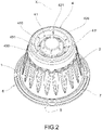
- the recessed region 41 is an annular groove, arranged annularly to the central axis X, as for example shown in Figures 1 to 8 .
- this annular groove is at least partially or totally defined by the first wall 420 and by the second wall 430.
- the first wall 420 is an annular inclined flat wall so that an imaginary extension thereof forms an acute angle of intersection ⁇ with a plane parallel to and passing through the central axis X.
- the second wall 430 is an annular inclined flat wall so that the angle of intersection ⁇ ', which an imaginary extension thereof forms with the plane parallel to and passing through the central axis X, is an obtuse angle.
- the angle of intersection ⁇ ' is understood as measured in the same direction of measurement as the angle of intersection ⁇ .
- the first wall 420 and the second wall 430 being flat walls, it is clear that the first imaginary plane P1 and the second imaginary plane P2 lie respectively on the first wall 420 and on the second wall 430.
- annular inclined flat wall means not only flat walls, but also means that this inclined flat wall, in a sectional view thereof along a plane passing through the central axis X, is a straight segment.
- first wall 420 has a frusto-conical shape that develops around the central axis X
- the second wall 430 has a frusto-conical shape that develops around the central axis X at a distance from the first wall 420 and preferably with inverted taper.
- the first wall 420 and the second wall 430 while not being annular walls, are not flat walls, but rather are curved walls or are curved walls at times or flat at times. In this case, therefore, as is clarified in Figure 5 , there will be at least one point or region of the first wall 420 or of the second wall 430, wherein the first imaginary plane P1 or the second imaginary plane P2 will each be tangent to such point or region of the first wall 420 or the second wall 430.
- the extension of the first imaginary plane P1 forms an acute angle of intersection ⁇ with a plane parallel to and passing through the central axis X
- the extension of the second imaginary plane P2 forms with the plane parallel to and passing through the central axis X an obtuse angle of intersection ⁇ '.
- angle of intersection ⁇ ' means measured in the same direction of measurement as the angle of intersection ⁇ .
- the connecting wall 410 is a flat annular wall perpendicular to the central axis X and forming the bottom of the annular groove.
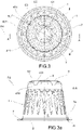
- each hole of the first wall holes 421 is arranged in front of a respective second wall hole 431, preferably in such a way that an imaginary plane P4 parallel to the central axis X and passing through the center of each first wall hole 421 and the center of a second wall hole 431 also passes through the central axis X, as, for example, shown in Figures 2 and 3 .
- the first wall holes 421 are arranged along a first imaginary circumference C3 around the central axis X and are circumferentially equidistant from each other
- the second wall holes 431 are arranged along a second imaginary circumference C1 around the central axis X and are circumferentially equidistant from each other.
- the circumference C1 is spaced from and coaxial to the circumference C2 around the axis X.
- the bottom holes 411 are arranged interspersed with respect to the first wall holes 421 and the second wall holes 431.
- this imaginary line I does not intersect the center of a bottom hole 411 and, preferably, does not intersect the entire bottom hole 411, and even more preferably does not intersect any bottom hole 411.
- the bottom holes 411 are arranged along a third imaginary circumference C2, which is concentric and interposed between the first C3 and the second imaginary circumference C1, as for example shown in Figure XX.
- the bottom holes 411 are circumferentially equidistant from each other by an angle at the center ⁇ equal to the angle at the center ⁇ of which the first wall holes 421 and/or the second wall holes 431 are circumferentially spaced from each other.
- all the first wall holes 421, the second wall holes 431 and the bottom holes 411 have a circular shape. This embodiment is preferred for cups 1 made by thermoforming.
- the holes on the first wall 421 and the holes on the second wall 431 have a square shape, while the holes on the bottom 411 have a circular shape.
- This embodiment is preferred for cups 1 made by injection molding.
- cup 1 comprises at least six bottom holes 411, at least six first wall holes 421 and at least six second wall holes 431.
- a further variant embodiment of the capsule 10 comprises at least one fin 50, 51 near at least one first wall hole 421 and/or at least one second wall hole 431.
- a fin 50, 51 protrudes towards the inside of the inner cavity 11.
- This fin is made by folding along the edge 421', 431' of the first wall hole 421 and/or the second wall hole 431.
- the edge 421', 431' is the only anchoring region of the fin 50, 51 to the first wall 420 or to the second wall 430.
- this fin 50, 51 has a shape complementary to the shape of the first wall hole 421 or of the second wall hole 431.
- the fin 50, 51 is inclined at an angle between 80 and 100° with respect to the first imaginary plane P1 if it projects from the first wall 420 or to the second imaginary plane P2 if it projects from the second wall 430.
- the cup 1 is obtained by thermoforming starting from a multilayer sheet comprising an inner barrier-like layer arranged between two outer layers.
- the multilayer sheet is of the PP/EVOH/PP type, i.e., the barrier layer is made of ethylene vinyl alcohol (EVOH) material arranged between two outer layers of polypropylene (PP).
- EVOH ethylene vinyl alcohol
- the method comprises the steps of:
- a portion of said first wall 421 and/or of said second wall 431 is folded in a manner that at least one fin 50, 51 protrudes from said first 420 and/or second wall 430 towards the inner cavity 11.
- a cutting head comprising cutting or punching elements 101', 101" suitable for cutting the first or second wall 420, 430 to create the first or second wall holes 421, 431 and at the same time folding a portion of this first or second wall towards the inside of the cup 1 in the inner cavity 11 and obtaining the fin 50, 51.
- each cutting or punching element 101', 101" comprises an inclined wall 101b, lying on an inclined plane intersecting the central axis X of the cup 1, so that this inclined wall 101b, in its movement of approaching and crossing the bottom wall 4 of the cup 1, folds a portion of the first 420 or the second wall 430 of the cup so as to create the fin 50, 51 and guide it towards the final position of inclination.
- each cutting or punching element 101', 101" preferably also comprises at least one vertical wall, substantially parallel to the central axis X of the cup, joined to the inclined wall 101b, so as to form a tip in the joint region suitable to cut the first 420 or the second wall 430 to make the first wall hole 421 or the second wall hole 431.
- a first wall hole 421 or a second wall hole 431 is made provided with a fin 50,51 or without a fin 50, 51, i.e. a simple through hole, in the cutting or punching step
- the cutting elements 101', 101" in their movement through the bottom wall 4 of the cup 1 are each accommodated at least partially in a punch seat 100a, 100b, 100c, obtained in the punch 100.
- a punch seat 100a, 100b, 100c obtained in the punch 100.
- the cup 1 of the capsule 10 is obtained by thermoforming.
- the cup is made from a multilayer sheet comprising an inner barrier-type layer.
- this barrier layer is fully wrapped within the adjacent layers of the multilayer sheet. In other words, the inner barrier-like layer never comes in contact with the outside.
- the inner layer is an oxygen barrier layer and is made of ethylene vinyl alcohol (EVOH) material.
- EVOH ethylene vinyl alcohol
- the multilayer sheet is of the PP/EVOH/PP type wherein polypropylene (PP) forms the outer layers of the sheet, i.e. the layers that wrap around and contain the inner barrier layer.
- PP polypropylene
- At least one outer layer of the multilayer sheet is made of polyethylene (PE), and this layer forms the rear face 7a of the collar 7, which is intended to engage with an abutment edge of the infusion chamber of the extraction device.
- PE polyethylene
- the multilayer sheet is of the PP/EVOH/PP/PE type.
- the cup is obtained by injection molding of a plastic material, for example made of PBT.
- the capsule according to the present invention overcomes the drawbacks mentioned with reference to the prior art, as it allows one to create a capsule that, due to the presence of holes arranged on both the first wall 420 and the second wall 430, allows the infusion water to be distributed in an optimal way in the food product to be infused and thus allows a beverage to be obtained with improved flavor with respect to the capsules of the prior art without this solution.
- the solution according to the present invention maintains a constructive geometry that is easy to obtain.
- the plurality of holes obtained directly on the cup with the surprising effect of improved the quality of the extracted beverage, especially with regards to coffee, does not require additional components to the cup (such as filters or micro-perforated shower elements) and does not require special measures during the molding step of the cup.
- the capsule according to the present invention may be used in different types of extraction machines ensuring an improved quality of the extracted beverage, regardless of the type of extraction machine.
- the capsule according to the present invention is easily obtainable through a thermoforming process.
- a variant embodiment provides for the presence of fins able to direct at will, according to the inclination of the fin, the flow of liquid within the cavity inside the cup and further improve the diffusion of the liquid.
- This variant is also simple to implement and does not require additional components to the cup or additional material.
- the fins are made in the same step as making the holes, thus allowing an improved production efficiency of the single capsule in terms of production time.
Landscapes
- Engineering & Computer Science (AREA)
- Mechanical Engineering (AREA)
- Apparatus For Making Beverages (AREA)
- Medicinal Preparation (AREA)
Claims (15)
- Capsule (10) pour la préparation d'une boisson dans un dispositif d'extraction, ladite capsule (10) comprenant une coupelle (1) qui héberge une cavité interne (11) prévue pour contenir une substance alimentaire, ladite coupelle (1) comprenant :- une paroi inférieure (4) destinée à être pénétrée par un liquide injecté par le dispositif d'extraction,- une extrémité avant (6), opposée à la paroi inférieure (4), définissant une ouverture de distribution (5) destinée à être pénétrée par la boisson extraite,- une paroi latérale (2) s'étendant autour d'un axe central (X) et en hauteur le long dudit axe central (X) entre la paroi inférieure (4) et l'extrémité avant (6) ;ladite extrémité avant (6) comprenant un rebord (7) faisant saillie radialement vers l'extérieur à partir de la paroi latérale (2) ;ledit rebord (7) étant muni d'une face arrière (7a) faisant face à la paroi inférieure et adaptée pour fournir un joint d'étanchéité lorsque la capsule (10) est insérée dans le dispositif d'extraction ;ladite paroi inférieure (4) comprenant une région en retrait (41) vers la cavité interne (3) ;ladite capsule (10) comprenant un couvercle inférieur (9) qui ferme la région en retrait (41) et un couvercle de distribution (8) qui ferme l'ouverture de distribution (5),ledit axe central (X) étant perpendiculaire au couvercle inférieur (9),ladite capsule (10) étant caractérisée en ce que la région en retrait (41) est définie au moins par une première paroi (420) et une seconde paroi (430) se faisant face et espacées le long d'une direction radiale (Y) perpendiculaire à l'axe central (X), ladite première paroi (420) et ladite seconde paroi (430) étant réunies par une paroi de liaison (410) qui ne croise pas l'axe central (X),dans lequel, étant définis un premier plan imaginaire (P1) tangent à au moins une partie de la première paroi (420) et un second plan imaginaire (P2) tangent à au moins une partie de la seconde paroi (430), ledit premier plan imaginaire (P1) et ledit second plan imaginaire (P2) sont inclinés de façon à faire intersection avec l'axe central (X),et dans lequel sur ladite première paroi (420) et sur ladite seconde paroi (430), des trous de première paroi (421) et des trous de seconde paroi (431) sont formés, respectivement, pour le passage du liquide injecté par le dispositif d'extraction dans la cavité interne (11).
- Capsule (1) selon la revendication 1, dans laquelle un plan imaginaire horizontal (P3) est défini de manière tangente à au moins une partie de la paroi de liaison (410), ledit plan imaginaire horizontal est perpendiculaire à l'axe central (X), et dans lequel des trous inférieurs (411) sont formés dans ladite paroi de liaison (410) pour le passage du liquide injecté par le dispositif d'extraction dans la cavité interne (11).
- Capsule (10) selon la revendication 1 ou 2, dans laquelle la région en retrait (41) est une rainure annulaire, agencée de manière annulaire par rapport à l'axe central (X).
- Capsule (10) selon la revendication 3, dans laquelle la rainure annulaire est au moins partiellement ou totalement définie par la première paroi (420) et la seconde paroi (430), dans laquelle ladite première paroi (420) est une paroi inclinée annulaire plate d'une manière telle qu'une extension imaginaire de celle-ci forme un angle d'intersection (α) aigu avec un plan parallèle passant par l'axe central (X) et dans laquelle ladite seconde paroi (430) est une paroi plane inclinée annulaire d'une manière telle que l'angle d'intersection (α) qu'une extension imaginaire de celle-ci forme avec le plan parallèle à et passant par l'axe central (X) est un angle obtus.
- Capsule (10) selon la revendication 3, dans laquelle la première paroi (420) possède une forme tronconique qui se développe autour de l'axe central (X) et la seconde paroi (430) possède une forme tronconique qui se développe autour de l'axe central (X) à une certaine distance par rapport à la première paroi (420), de préférence à cône renversé.
- Capsule (10) selon la revendication 4 ou 5, dans laquelle la paroi de liaison (410) est une paroi plate annulaire perpendiculaire à l'axe central (X) et formant le fond de la rainure annulaire.
- Capsule (10) selon l'une quelconque des revendications précédentes, dans laquelle chaque trou des trous de première paroi (421) est agencé devant un trou de seconde paroi (431) respectif, de préférence d'une manière telle qu'un plan imaginaire (P4) parallèle à l'axe central (X) passant par le centre de chaque trou de première paroi (421) et le centre d'un trou de seconde paroi (431) passe également par l'axe central (X).
- Capsule (10) selon l'une quelconque des revendications précédentes, dans laquelle les trous de première paroi (421) sont agencés le long d'une première circonférence imaginaire (C3) autour de l'axe central (X) et sont espacés de manière circonférentielle les uns des autres et les trous de seconde paroi (431) sont agencés le long d'une deuxième circonférence imaginaire (C1) autour de l'axe central (X) et sont espacés de manière circonférentielle les uns des autres.
- Capsule (10) selon l'une quelconque des revendications 2 à 8, dans laquelle les trous inférieurs (411) sont agencés d'une manière alternés par rapport aux trous de première paroi (421) et aux trous de seconde paroi (431).
- Capsule (10) selon la revendication 9, dans laquelle les trous inférieurs (411) sont agencés le long d'une troisième circonférence imaginaire (C2), concentrique et interposée entre la première (C3) et la deuxième circonférence imaginaire (C1).
- Capsule (10) selon l'une quelconque des revendications 2 à 10, comprenant au moins six trous inférieurs (411), au moins six trous de première paroi (421) et au moins six trous de seconde paroi (431).
- Capsule (10) selon l'une quelconque des revendications précédentes, dans laquelle à partir d'un bord (421', 431') d'au moins un trou de première paroi (421) et/ou d'au moins un trou de seconde paroi (431), fait saillie une ailette (50, 51) vers l'intérieur de la cavité interne (11).
- Capsule (10) selon l'une quelconque des revendications précédentes, dans laquelle la coupelle (1) est obtenue par thermoformage en partant d'une feuille multicouche comprenant une couche interne de type barrière agencée entre deux couches externes.
- Procédé de fabrication d'une coupelle (1) d'une capsule (10) selon l'une quelconque des revendications précédentes, comprenant les étapes de :- le moulage d'une coupelle (1) constituée de matière plastique d'un seul tenant, ladite coupelle moulée comprenant une paroi inférieure (4), une extrémité avant (6), opposée à la paroi inférieure (4), définissant une ouverture de distribution (5) destinée à être traversée par la boisson extraite, une paroi latérale (2) s'étendant autour d'un axe central (X) et en hauteur le long dudit axe central (X) entre la paroi inférieure (4) et l'extrémité avant (6) ;ladite extrémité avant (6) comprenant un rebord (7) faisant saillie radialement vers l'extérieur à partir de la paroi latérale (2) ;ledit rebord (7) étant muni d'une face arrière (7a) faisant face à la paroi inférieure et adaptée pour fournir un joint d'étanchéité lorsque la capsule (10) est insérée dans le dispositif d'extraction ;ladite paroi inférieure (4) comprenant une région en retrait (41) vers la cavité interne (11),dans lequel la région en retrait (41) est définie au moins par une première paroi (420) et une seconde paroi (430) se faisant face et espacées le long d'une direction radiale (Y) perpendiculaire à l'axe central (X), ladite première paroi (420) et ladite seconde paroi (430) étant réunies par une paroi de liaison (410) qui ne croise pas l'axe central (X),dans lequel, étant définis un premier plan imaginaire (P1) tangent à au moins une partie de la première paroi (420) et un second plan imaginaire (P2) tangent à au moins une partie de la seconde paroi (430), ledit premier plan imaginaire (P1) et ledit second plan imaginaire (P2) sont inclinés de façon à faire intersection avec l'axe central (X) ;- l'insertion de la coupelle (1) dans une machine de découpe ou de poinçonnage comprenant un poinçon (100) reposant sur la paroi inférieure (4) sur le côté de la cavité interne (3) ;- au moyen d'une tête de découpe ou de poinçonnage (101), la découpe ou le poinçonnage, de préférence simultanément, de ladite première paroi (420) et de ladite seconde paroi (431) pour créer des trous de première paroi (421) sur ladite première paroi (420) et des trous de seconde paroi (431) sur ladite seconde paroi (430).
- Procédé selon la revendication 14, dans lequel à l'étape de découpe ou de poinçonnage de ladite première paroi (420) et de ladite seconde paroi (431), une partie de ladite première paroi (421) et/ou de ladite seconde paroi (431) est pliée d'une manière telle qu'au moins une ailette (50, 51) fasse saillie à partir de ladite première et/ou seconde paroi (420, 430) vers la cavité interne (11).
Applications Claiming Priority (2)
| Application Number | Priority Date | Filing Date | Title |
|---|---|---|---|
| IT102018000010741A IT201800010741A1 (it) | 2018-11-30 | 2018-11-30 | Capsula per la preparazione di bevande ad infusione ad estrazione migliorata |
| PCT/IB2019/058863 WO2020109883A1 (fr) | 2018-11-30 | 2019-10-17 | Capsule pour la préparation de boissons infusées à extraction améliorée |
Publications (2)
| Publication Number | Publication Date |
|---|---|
| EP3887285A1 EP3887285A1 (fr) | 2021-10-06 |
| EP3887285B1 true EP3887285B1 (fr) | 2022-11-23 |
Family
ID=65767188
Family Applications (1)
| Application Number | Title | Priority Date | Filing Date |
|---|---|---|---|
| EP19804840.7A Active EP3887285B1 (fr) | 2018-11-30 | 2019-10-17 | Capsule pour la preparation de boissons |
Country Status (4)
| Country | Link |
|---|---|
| EP (1) | EP3887285B1 (fr) |
| ES (1) | ES2933607T3 (fr) |
| IT (1) | IT201800010741A1 (fr) |
| WO (1) | WO2020109883A1 (fr) |
Families Citing this family (2)
| Publication number | Priority date | Publication date | Assignee | Title |
|---|---|---|---|---|
| IT202200022002A1 (it) * | 2022-10-25 | 2024-04-25 | Bisio Progetti Spa | Coppa termoformata monopezzo per capsule auto-aprentesi |
| WO2025219792A1 (fr) * | 2024-04-16 | 2025-10-23 | Guala Dispensing Fp S.P.A. | Coupelle en cellulose et capsule associée pour boissons |
Family Cites Families (3)
| Publication number | Priority date | Publication date | Assignee | Title |
|---|---|---|---|---|
| PL2394932T3 (pl) * | 2010-06-11 | 2013-10-31 | Alain Frydman | Kapsułka z osłabioną strefą zerwania |
| WO2012010760A1 (fr) * | 2010-06-11 | 2012-01-26 | Alain Frydman | Capsule pour l'extraction d'une boisson sous pression |
| US20140130678A1 (en) * | 2011-06-01 | 2014-05-15 | Alain Frydman | Capsule for pressurized drink extraction |
-
2018
- 2018-11-30 IT IT102018000010741A patent/IT201800010741A1/it unknown
-
2019
- 2019-10-17 WO PCT/IB2019/058863 patent/WO2020109883A1/fr not_active Ceased
- 2019-10-17 ES ES19804840T patent/ES2933607T3/es active Active
- 2019-10-17 EP EP19804840.7A patent/EP3887285B1/fr active Active
Also Published As
| Publication number | Publication date |
|---|---|
| WO2020109883A1 (fr) | 2020-06-04 |
| IT201800010741A1 (it) | 2020-05-30 |
| EP3887285A1 (fr) | 2021-10-06 |
| ES2933607T3 (es) | 2023-02-10 |
Similar Documents
| Publication | Publication Date | Title |
|---|---|---|
| JP5836353B2 (ja) | 飲料を調製するためのカートリッジおよび方法 | |
| EP3261958B1 (fr) | Capsule pour la préparation de boissons infusées ou solubles | |
| EP1440904B1 (fr) | Cartouche pour la préparation de boissons et méthode de fabrication de cartouche | |
| EP1440903B1 (fr) | Cartouche pour la préparation de boissons | |
| RU2762247C2 (ru) | Способ изготовления чашки для капсулы для настоев или растворимых напитков и соответствующие чашка и капсула | |
| GB2411106A (en) | Cartridge for the preparation of beverages | |
| EP3294646B1 (fr) | Capsule jetable pour machines de préparation de boissons infusées | |
| GB2407758A (en) | Cartridge and method for the preparation of beverages | |
| KR101775033B1 (ko) | 개선된 음료 조리 기계 | |
| RU2743904C2 (ru) | Капсула для приготовления настоев и растворимых напитков | |
| JP4431135B2 (ja) | 飲料を調製するためのカートリッジ | |
| EP3887285B1 (fr) | Capsule pour la preparation de boissons | |
| GB2397506A (en) | Beverage cartridge | |
| GB2397508A (en) | Cartridge system for the preparation of beverages | |
| GB2397493A (en) | Cartridge for the preparation of beverages | |
| GB2397502A (en) | Cartridge for the preparation of beverages | |
| HK1065764B (en) | Cartridge for the preparation of beverages | |
| HK1102184B (en) | Cartridge for the preparation of beverages |
Legal Events
| Date | Code | Title | Description |
|---|---|---|---|
| STAA | Information on the status of an ep patent application or granted ep patent |
Free format text: STATUS: UNKNOWN |
|
| STAA | Information on the status of an ep patent application or granted ep patent |
Free format text: STATUS: THE INTERNATIONAL PUBLICATION HAS BEEN MADE |
|
| PUAI | Public reference made under article 153(3) epc to a published international application that has entered the european phase |
Free format text: ORIGINAL CODE: 0009012 |
|
| STAA | Information on the status of an ep patent application or granted ep patent |
Free format text: STATUS: REQUEST FOR EXAMINATION WAS MADE |
|
| 17P | Request for examination filed |
Effective date: 20210304 |
|
| AK | Designated contracting states |
Kind code of ref document: A1 Designated state(s): AL AT BE BG CH CY CZ DE DK EE ES FI FR GB GR HR HU IE IS IT LI LT LU LV MC MK MT NL NO PL PT RO RS SE SI SK SM TR |
|
| DAV | Request for validation of the european patent (deleted) | ||
| DAX | Request for extension of the european patent (deleted) | ||
| GRAP | Despatch of communication of intention to grant a patent |
Free format text: ORIGINAL CODE: EPIDOSNIGR1 |
|
| STAA | Information on the status of an ep patent application or granted ep patent |
Free format text: STATUS: GRANT OF PATENT IS INTENDED |
|
| INTG | Intention to grant announced |
Effective date: 20220623 |
|
| GRAS | Grant fee paid |
Free format text: ORIGINAL CODE: EPIDOSNIGR3 |
|
| GRAA | (expected) grant |
Free format text: ORIGINAL CODE: 0009210 |
|
| STAA | Information on the status of an ep patent application or granted ep patent |
Free format text: STATUS: THE PATENT HAS BEEN GRANTED |
|
| AK | Designated contracting states |
Kind code of ref document: B1 Designated state(s): AL AT BE BG CH CY CZ DE DK EE ES FI FR GB GR HR HU IE IS IT LI LT LU LV MC MK MT NL NO PL PT RO RS SE SI SK SM TR |
|
| REG | Reference to a national code |
Ref country code: GB Ref legal event code: FG4D |
|
| REG | Reference to a national code |
Ref country code: CH Ref legal event code: EP |
|
| REG | Reference to a national code |
Ref country code: DE Ref legal event code: R081 Ref document number: 602019022318 Country of ref document: DE Owner name: BISIO PROGETTI S.P.A., IT Free format text: FORMER OWNER: BISIO PROGETTI S.P.A., ALESSANDRIA, IT |
|
| REG | Reference to a national code |
Ref country code: AT Ref legal event code: REF Ref document number: 1533026 Country of ref document: AT Kind code of ref document: T Effective date: 20221215 Ref country code: DE Ref legal event code: R096 Ref document number: 602019022318 Country of ref document: DE |
|
| REG | Reference to a national code |
Ref country code: IE Ref legal event code: FG4D |
|
| REG | Reference to a national code |
Ref country code: ES Ref legal event code: FG2A Ref document number: 2933607 Country of ref document: ES Kind code of ref document: T3 Effective date: 20230210 |
|
| REG | Reference to a national code |
Ref country code: LT Ref legal event code: MG9D |
|
| REG | Reference to a national code |
Ref country code: NL Ref legal event code: MP Effective date: 20221123 |
|
| REG | Reference to a national code |
Ref country code: AT Ref legal event code: MK05 Ref document number: 1533026 Country of ref document: AT Kind code of ref document: T Effective date: 20221123 |
|
| PG25 | Lapsed in a contracting state [announced via postgrant information from national office to epo] |
Ref country code: SE Free format text: LAPSE BECAUSE OF FAILURE TO SUBMIT A TRANSLATION OF THE DESCRIPTION OR TO PAY THE FEE WITHIN THE PRESCRIBED TIME-LIMIT Effective date: 20221123 Ref country code: PT Free format text: LAPSE BECAUSE OF FAILURE TO SUBMIT A TRANSLATION OF THE DESCRIPTION OR TO PAY THE FEE WITHIN THE PRESCRIBED TIME-LIMIT Effective date: 20230323 Ref country code: NO Free format text: LAPSE BECAUSE OF FAILURE TO SUBMIT A TRANSLATION OF THE DESCRIPTION OR TO PAY THE FEE WITHIN THE PRESCRIBED TIME-LIMIT Effective date: 20230223 Ref country code: LT Free format text: LAPSE BECAUSE OF FAILURE TO SUBMIT A TRANSLATION OF THE DESCRIPTION OR TO PAY THE FEE WITHIN THE PRESCRIBED TIME-LIMIT Effective date: 20221123 Ref country code: FI Free format text: LAPSE BECAUSE OF FAILURE TO SUBMIT A TRANSLATION OF THE DESCRIPTION OR TO PAY THE FEE WITHIN THE PRESCRIBED TIME-LIMIT Effective date: 20221123 Ref country code: AT Free format text: LAPSE BECAUSE OF FAILURE TO SUBMIT A TRANSLATION OF THE DESCRIPTION OR TO PAY THE FEE WITHIN THE PRESCRIBED TIME-LIMIT Effective date: 20221123 |
|
| PG25 | Lapsed in a contracting state [announced via postgrant information from national office to epo] |
Ref country code: RS Free format text: LAPSE BECAUSE OF FAILURE TO SUBMIT A TRANSLATION OF THE DESCRIPTION OR TO PAY THE FEE WITHIN THE PRESCRIBED TIME-LIMIT Effective date: 20221123 Ref country code: PL Free format text: LAPSE BECAUSE OF FAILURE TO SUBMIT A TRANSLATION OF THE DESCRIPTION OR TO PAY THE FEE WITHIN THE PRESCRIBED TIME-LIMIT Effective date: 20221123 Ref country code: LV Free format text: LAPSE BECAUSE OF FAILURE TO SUBMIT A TRANSLATION OF THE DESCRIPTION OR TO PAY THE FEE WITHIN THE PRESCRIBED TIME-LIMIT Effective date: 20221123 Ref country code: IS Free format text: LAPSE BECAUSE OF FAILURE TO SUBMIT A TRANSLATION OF THE DESCRIPTION OR TO PAY THE FEE WITHIN THE PRESCRIBED TIME-LIMIT Effective date: 20230323 Ref country code: HR Free format text: LAPSE BECAUSE OF FAILURE TO SUBMIT A TRANSLATION OF THE DESCRIPTION OR TO PAY THE FEE WITHIN THE PRESCRIBED TIME-LIMIT Effective date: 20221123 Ref country code: GR Free format text: LAPSE BECAUSE OF FAILURE TO SUBMIT A TRANSLATION OF THE DESCRIPTION OR TO PAY THE FEE WITHIN THE PRESCRIBED TIME-LIMIT Effective date: 20230224 |
|
| P01 | Opt-out of the competence of the unified patent court (upc) registered |
Effective date: 20230519 |
|
| PG25 | Lapsed in a contracting state [announced via postgrant information from national office to epo] |
Ref country code: NL Free format text: LAPSE BECAUSE OF FAILURE TO SUBMIT A TRANSLATION OF THE DESCRIPTION OR TO PAY THE FEE WITHIN THE PRESCRIBED TIME-LIMIT Effective date: 20221123 |
|
| PG25 | Lapsed in a contracting state [announced via postgrant information from national office to epo] |
Ref country code: SM Free format text: LAPSE BECAUSE OF FAILURE TO SUBMIT A TRANSLATION OF THE DESCRIPTION OR TO PAY THE FEE WITHIN THE PRESCRIBED TIME-LIMIT Effective date: 20221123 Ref country code: RO Free format text: LAPSE BECAUSE OF FAILURE TO SUBMIT A TRANSLATION OF THE DESCRIPTION OR TO PAY THE FEE WITHIN THE PRESCRIBED TIME-LIMIT Effective date: 20221123 Ref country code: EE Free format text: LAPSE BECAUSE OF FAILURE TO SUBMIT A TRANSLATION OF THE DESCRIPTION OR TO PAY THE FEE WITHIN THE PRESCRIBED TIME-LIMIT Effective date: 20221123 Ref country code: DK Free format text: LAPSE BECAUSE OF FAILURE TO SUBMIT A TRANSLATION OF THE DESCRIPTION OR TO PAY THE FEE WITHIN THE PRESCRIBED TIME-LIMIT Effective date: 20221123 Ref country code: CZ Free format text: LAPSE BECAUSE OF FAILURE TO SUBMIT A TRANSLATION OF THE DESCRIPTION OR TO PAY THE FEE WITHIN THE PRESCRIBED TIME-LIMIT Effective date: 20221123 |
|
| REG | Reference to a national code |
Ref country code: DE Ref legal event code: R097 Ref document number: 602019022318 Country of ref document: DE |
|
| PG25 | Lapsed in a contracting state [announced via postgrant information from national office to epo] |
Ref country code: SK Free format text: LAPSE BECAUSE OF FAILURE TO SUBMIT A TRANSLATION OF THE DESCRIPTION OR TO PAY THE FEE WITHIN THE PRESCRIBED TIME-LIMIT Effective date: 20221123 Ref country code: AL Free format text: LAPSE BECAUSE OF FAILURE TO SUBMIT A TRANSLATION OF THE DESCRIPTION OR TO PAY THE FEE WITHIN THE PRESCRIBED TIME-LIMIT Effective date: 20221123 |
|
| PLBE | No opposition filed within time limit |
Free format text: ORIGINAL CODE: 0009261 |
|
| STAA | Information on the status of an ep patent application or granted ep patent |
Free format text: STATUS: NO OPPOSITION FILED WITHIN TIME LIMIT |
|
| 26N | No opposition filed |
Effective date: 20230824 |
|
| PG25 | Lapsed in a contracting state [announced via postgrant information from national office to epo] |
Ref country code: SI Free format text: LAPSE BECAUSE OF FAILURE TO SUBMIT A TRANSLATION OF THE DESCRIPTION OR TO PAY THE FEE WITHIN THE PRESCRIBED TIME-LIMIT Effective date: 20221123 |
|
| PG25 | Lapsed in a contracting state [announced via postgrant information from national office to epo] |
Ref country code: MC Free format text: LAPSE BECAUSE OF FAILURE TO SUBMIT A TRANSLATION OF THE DESCRIPTION OR TO PAY THE FEE WITHIN THE PRESCRIBED TIME-LIMIT Effective date: 20221123 |
|
| REG | Reference to a national code |
Ref country code: CH Ref legal event code: PL |
|
| REG | Reference to a national code |
Ref country code: BE Ref legal event code: MM Effective date: 20231031 |
|
| PG25 | Lapsed in a contracting state [announced via postgrant information from national office to epo] |
Ref country code: LU Free format text: LAPSE BECAUSE OF NON-PAYMENT OF DUE FEES Effective date: 20231017 |
|
| PG25 | Lapsed in a contracting state [announced via postgrant information from national office to epo] |
Ref country code: LU Free format text: LAPSE BECAUSE OF NON-PAYMENT OF DUE FEES Effective date: 20231017 |
|
| PG25 | Lapsed in a contracting state [announced via postgrant information from national office to epo] |
Ref country code: CH Free format text: LAPSE BECAUSE OF NON-PAYMENT OF DUE FEES Effective date: 20231031 |
|
| PG25 | Lapsed in a contracting state [announced via postgrant information from national office to epo] |
Ref country code: CH Free format text: LAPSE BECAUSE OF NON-PAYMENT OF DUE FEES Effective date: 20231031 |
|
| PG25 | Lapsed in a contracting state [announced via postgrant information from national office to epo] |
Ref country code: BE Free format text: LAPSE BECAUSE OF NON-PAYMENT OF DUE FEES Effective date: 20231031 |
|
| PG25 | Lapsed in a contracting state [announced via postgrant information from national office to epo] |
Ref country code: IE Free format text: LAPSE BECAUSE OF NON-PAYMENT OF DUE FEES Effective date: 20231017 |
|
| PG25 | Lapsed in a contracting state [announced via postgrant information from national office to epo] |
Ref country code: IE Free format text: LAPSE BECAUSE OF NON-PAYMENT OF DUE FEES Effective date: 20231017 |
|
| PG25 | Lapsed in a contracting state [announced via postgrant information from national office to epo] |
Ref country code: BG Free format text: LAPSE BECAUSE OF FAILURE TO SUBMIT A TRANSLATION OF THE DESCRIPTION OR TO PAY THE FEE WITHIN THE PRESCRIBED TIME-LIMIT Effective date: 20221123 |
|
| PG25 | Lapsed in a contracting state [announced via postgrant information from national office to epo] |
Ref country code: BG Free format text: LAPSE BECAUSE OF FAILURE TO SUBMIT A TRANSLATION OF THE DESCRIPTION OR TO PAY THE FEE WITHIN THE PRESCRIBED TIME-LIMIT Effective date: 20221123 |
|
| REG | Reference to a national code |
Ref country code: ES Ref legal event code: PC2A Owner name: GUALA DISPENSING FP S.P.A. Effective date: 20250716 |
|
| PG25 | Lapsed in a contracting state [announced via postgrant information from national office to epo] |
Ref country code: CY Free format text: LAPSE BECAUSE OF FAILURE TO SUBMIT A TRANSLATION OF THE DESCRIPTION OR TO PAY THE FEE WITHIN THE PRESCRIBED TIME-LIMIT; INVALID AB INITIO Effective date: 20191017 |
|
| PG25 | Lapsed in a contracting state [announced via postgrant information from national office to epo] |
Ref country code: HU Free format text: LAPSE BECAUSE OF FAILURE TO SUBMIT A TRANSLATION OF THE DESCRIPTION OR TO PAY THE FEE WITHIN THE PRESCRIBED TIME-LIMIT; INVALID AB INITIO Effective date: 20191017 |
|
| PGFP | Annual fee paid to national office [announced via postgrant information from national office to epo] |
Ref country code: IT Payment date: 20250926 Year of fee payment: 7 |
|
| PGFP | Annual fee paid to national office [announced via postgrant information from national office to epo] |
Ref country code: FR Payment date: 20250930 Year of fee payment: 7 |
|
| PG25 | Lapsed in a contracting state [announced via postgrant information from national office to epo] |
Ref country code: TR Free format text: LAPSE BECAUSE OF FAILURE TO SUBMIT A TRANSLATION OF THE DESCRIPTION OR TO PAY THE FEE WITHIN THE PRESCRIBED TIME-LIMIT Effective date: 20221123 |
|
| PGFP | Annual fee paid to national office [announced via postgrant information from national office to epo] |
Ref country code: DE Payment date: 20251027 Year of fee payment: 7 |
|
| PGFP | Annual fee paid to national office [announced via postgrant information from national office to epo] |
Ref country code: GB Payment date: 20251022 Year of fee payment: 7 |
|
| PGFP | Annual fee paid to national office [announced via postgrant information from national office to epo] |
Ref country code: ES Payment date: 20251103 Year of fee payment: 7 |