EP3887702B1 - Verbinderanordnung und kühlsystem mit einer solchen anordnung - Google Patents
Verbinderanordnung und kühlsystem mit einer solchen anordnung Download PDFInfo
- Publication number
- EP3887702B1 EP3887702B1 EP18815966.9A EP18815966A EP3887702B1 EP 3887702 B1 EP3887702 B1 EP 3887702B1 EP 18815966 A EP18815966 A EP 18815966A EP 3887702 B1 EP3887702 B1 EP 3887702B1
- Authority
- EP
- European Patent Office
- Prior art keywords
- collar structure
- connector assembly
- spigot
- snap
- assembly according
- Prior art date
- Legal status (The legal status is an assumption and is not a legal conclusion. Google has not performed a legal analysis and makes no representation as to the accuracy of the status listed.)
- Active
Links
Images

Classifications
-
- F—MECHANICAL ENGINEERING; LIGHTING; HEATING; WEAPONS; BLASTING
- F28—HEAT EXCHANGE IN GENERAL
- F28F—DETAILS OF HEAT-EXCHANGE AND HEAT-TRANSFER APPARATUS, OF GENERAL APPLICATION
- F28F9/00—Casings; Header boxes; Auxiliary supports for elements; Auxiliary members within casings
- F28F9/02—Header boxes; End plates
- F28F9/0246—Arrangements for connecting header boxes with flow lines
- F28F9/0256—Arrangements for coupling connectors with flow lines
- F28F9/0258—Arrangements for coupling connectors with flow lines of quick acting type, e.g. with snap action
-
- F—MECHANICAL ENGINEERING; LIGHTING; HEATING; WEAPONS; BLASTING
- F16—ENGINEERING ELEMENTS AND UNITS; GENERAL MEASURES FOR PRODUCING AND MAINTAINING EFFECTIVE FUNCTIONING OF MACHINES OR INSTALLATIONS; THERMAL INSULATION IN GENERAL
- F16L—PIPES; JOINTS OR FITTINGS FOR PIPES; SUPPORTS FOR PIPES, CABLES OR PROTECTIVE TUBING; MEANS FOR THERMAL INSULATION IN GENERAL
- F16L37/00—Couplings of the quick-acting type
- F16L37/008—Couplings of the quick-acting type for branching pipes; for joining pipes to walls
-
- F—MECHANICAL ENGINEERING; LIGHTING; HEATING; WEAPONS; BLASTING
- F16—ENGINEERING ELEMENTS AND UNITS; GENERAL MEASURES FOR PRODUCING AND MAINTAINING EFFECTIVE FUNCTIONING OF MACHINES OR INSTALLATIONS; THERMAL INSULATION IN GENERAL
- F16L—PIPES; JOINTS OR FITTINGS FOR PIPES; SUPPORTS FOR PIPES, CABLES OR PROTECTIVE TUBING; MEANS FOR THERMAL INSULATION IN GENERAL
- F16L41/00—Branching pipes; Joining pipes to walls
- F16L41/001—Branching pipes; Joining pipes to walls the wall being a pipe plate
-
- F—MECHANICAL ENGINEERING; LIGHTING; HEATING; WEAPONS; BLASTING
- F16—ENGINEERING ELEMENTS AND UNITS; GENERAL MEASURES FOR PRODUCING AND MAINTAINING EFFECTIVE FUNCTIONING OF MACHINES OR INSTALLATIONS; THERMAL INSULATION IN GENERAL
- F16L—PIPES; JOINTS OR FITTINGS FOR PIPES; SUPPORTS FOR PIPES, CABLES OR PROTECTIVE TUBING; MEANS FOR THERMAL INSULATION IN GENERAL
- F16L41/00—Branching pipes; Joining pipes to walls
- F16L41/08—Joining pipes to walls or pipes, the joined pipe axis being perpendicular to the plane of a wall or to the axis of another pipe
-
- F—MECHANICAL ENGINEERING; LIGHTING; HEATING; WEAPONS; BLASTING
- F16—ENGINEERING ELEMENTS AND UNITS; GENERAL MEASURES FOR PRODUCING AND MAINTAINING EFFECTIVE FUNCTIONING OF MACHINES OR INSTALLATIONS; THERMAL INSULATION IN GENERAL
- F16L—PIPES; JOINTS OR FITTINGS FOR PIPES; SUPPORTS FOR PIPES, CABLES OR PROTECTIVE TUBING; MEANS FOR THERMAL INSULATION IN GENERAL
- F16L47/00—Connecting arrangements or other fittings specially adapted to be made of plastics or to be used with pipes made of plastics
- F16L47/26—Connecting arrangements or other fittings specially adapted to be made of plastics or to be used with pipes made of plastics for branching pipes; for joining pipes to walls; Adaptors therefor
- F16L47/28—Joining pipes to walls or to other pipes, the axis of the joined pipe being perpendicular to the wall or to the axis of the other pipe
-
- F—MECHANICAL ENGINEERING; LIGHTING; HEATING; WEAPONS; BLASTING
- F16—ENGINEERING ELEMENTS AND UNITS; GENERAL MEASURES FOR PRODUCING AND MAINTAINING EFFECTIVE FUNCTIONING OF MACHINES OR INSTALLATIONS; THERMAL INSULATION IN GENERAL
- F16L—PIPES; JOINTS OR FITTINGS FOR PIPES; SUPPORTS FOR PIPES, CABLES OR PROTECTIVE TUBING; MEANS FOR THERMAL INSULATION IN GENERAL
- F16L5/00—Devices for use where pipes, cables or protective tubing pass through walls or partitions
- F16L5/02—Sealing
- F16L5/027—Sealing by means of a joint of the quick-acting type
-
- F—MECHANICAL ENGINEERING; LIGHTING; HEATING; WEAPONS; BLASTING
- F28—HEAT EXCHANGE IN GENERAL
- F28F—DETAILS OF HEAT-EXCHANGE AND HEAT-TRANSFER APPARATUS, OF GENERAL APPLICATION
- F28F9/00—Casings; Header boxes; Auxiliary supports for elements; Auxiliary members within casings
- F28F9/02—Header boxes; End plates
- F28F9/0246—Arrangements for connecting header boxes with flow lines
- F28F9/0248—Arrangements for sealing connectors to header boxes
-
- Y—GENERAL TAGGING OF NEW TECHNOLOGICAL DEVELOPMENTS; GENERAL TAGGING OF CROSS-SECTIONAL TECHNOLOGIES SPANNING OVER SEVERAL SECTIONS OF THE IPC; TECHNICAL SUBJECTS COVERED BY FORMER USPC CROSS-REFERENCE ART COLLECTIONS [XRACs] AND DIGESTS
- Y02—TECHNOLOGIES OR APPLICATIONS FOR MITIGATION OR ADAPTATION AGAINST CLIMATE CHANGE
- Y02E—REDUCTION OF GREENHOUSE GAS [GHG] EMISSIONS, RELATED TO ENERGY GENERATION, TRANSMISSION OR DISTRIBUTION
- Y02E60/00—Enabling technologies; Technologies with a potential or indirect contribution to GHG emissions mitigation
- Y02E60/10—Energy storage using batteries
Definitions
- the invention relates to a flow connector assembly for liquid flows, for example for cooling liquids.
- the mounting normally requires tools, e.g. for screwing to generate a sufficient contact pressure for sealing the connection. This is burdensome and a source of potential errors.
- the invention seeks to overcome these problems by providing a compact, light and easy to use connector assembly, plate for use with such an assembly and a cooling system including such an assembly.
- the invention relates to a connector assembly, for example for coolants or cooling liquids, including a plate having an orifice and a spigot, said spigot having an internal flow path for liquid, and connector means for connecting the spigot to the metal plate so as to guide the liquid flowing in the flow path through the orifice, said connector means including a protruding collar structure surrounding the orifice.
- the connector means further includes a ring-shaped snap-on module configured to be fitted over the collar structure, said snap-on module including a cylindrical insertion part configured to be inserted into an orifice of said collar structure, wherein a remote end of the cylindrical insertion part in the insertion direction is provided with first snap-on structures engaging with the collar structure.
- the snap-on module enables an easy assembly even without tools while providing a reliable, robust and precise connection structure for the spigot.
- the invention in particular in the embodiment with the snap-on module, lends itself in particular to applications where the spigot has to be mounted from the outside of the container or receptacle if there is no possibility reach the inside thereof.
- said collar structure is integrally made of the sheet metal of said sheet metal plate by a sheet metal forming process and in that a male end of said spigot is configured to be inserted in said collar structure and locked in place by interacting with said connector means.
- the sheet metal forming process may include different techniques such as stamping, deep-drawing, punching, blanking, stamping, embossing, bending, forming, tap extrusion or coil extrusion, optionally complemented by laser cutting.
- the collar could be formed by 3D-printing, molding or casting.
- the cylindrical inner wall of the insertion part of the ring-shaped snap-on module is provided a notch configured to receive an O-ring.
- the first O-ring can provide a reliable sealing between the inner wall of the orifice in the snap-on module and the outer wall of the male end of the spigot.
- an inner circumference of the collar structure includes a structure such as a notch or a flange configured to support a second O-ring to be arranged between collar structure and the outer wall of the insertion part.
- the second O-ring can ensure a reliable sealing between the snap-on module and the collar structure.
- the ring-shaped snap-on module further includes an outer wall surrounding said collar structure and a second O-ring provided in a gap between the outer wall of the snap-on module and the collar structure.
- the second O-ring can ensure a reliable sealing between the snap-on module and the collar structure.
- the O-ring on the inner side of the collar structure and the O-ring on the outer side of the collar structure may be used alone or in combination.
- the ring-shaped snap-on module is a plastic part.
- the plastic can be chosen according to the chemical and thermal requirements imposed by the application and may include fibre reinforcement or metal reinforcement if necessary.
- the collar structure is a cylindrical double layer structure obtained by folding the sheet metal back, the rim of the sheet metal being arranged on the inside of the collar structure.
- the rim may then be used as a stable, sharp and well-defined engagement point for latching structures of the spigot or of the ring-shaped snap-on module.
- the male end of said spigot includes at least one latching structure on a radial outside surface of its end portion, said latching structures being configured to interact with corresponding latching structures on a cylindrical inner surface of said connector means.
- the latching structure on the radial outside surface of the end portion of the spigot is configured to engage around a rim of the cylindrical inner surface of said connector means.
- the cylindrical inner surface of said connector means is a cylindrical inner surface of said ring-shaped snap-on module.
- a yet further aspect of the invention relates to a cooling system, in particular for battery assemblies, including a connector assembly as defined above.
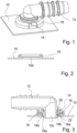
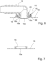
- Figure 1 and 3 show a connector assembly according to a first embodiment of the invention.
- the connector assembly is configured for use in a battery cooling system of an electric or hybrid vehicle and guides the cooling liquid to a heat exchanger.
- One of the walls of the heat exchanger is a sheet metal plate 10 having an orifice 10a and a spigot 12 to be attached to the orifice 10a.
- the spigot 12 has an internal, angular flow path for liquid, e.g. coolant or water ending in an orifice 10c arranged within the orifice 10a.
- Connector means 14 are provided for connecting the spigot 12 to the metal plate 10 so as to guide the liquid flowing in the flow path through the orifice 10c.
- the connector means 14 include a protruding collar structure 16 surrounding the orifice 10a.
- the collar structure 16 is integrally made of the sheet metal of said sheet metal plate 10 by a sheet metal forming process such as punching and deep-drawing.
- the circular cylindrical collar structure 16 protrudes from the sheet metal plate 10 as a roughly cylinder-barrel shaped circular wall in a direction perpendicular to a main plane or tangential plane of the sheet metal plate 10.
- the collar structure 16 lends stability to the connection between the spigot 12 and the sheet metal plate 10 and stabilizes the rim of the orifice 10a provided in the centre of the collar structure 16.
- the collar structure 16 has double layer structure obtained by folding the sheet metal back, the rim of the sheet metal being arranged on the inside of the collar structure 16.
- the connector means 14 further includes a ring-shaped snap-on module 18 formed as an injection-moulded plastic part configured to be fitted over the collar structure 16.
- the snap-on module 18 includes a cylindrical insertion part 18a configured to be inserted into an orifice 10a of said collar structure 16, wherein a remote end of the cylindrical insertion part 18a in the insertion direction is provided with a plurality of latches 18b with snap-fitting protrusions protruding radially outward as first snap-on structures engaging with the lower rim of the collar structure 16.
- the latches 18b When inserting the cylindrical insertion part 18a into the orifice 10a of the collar structure 16, the latches 18b are deflected radially inward and snap back upon reaching the final engagement position.
- the cylindrical inner wall of the insertion part 18a of the ring-shaped snap-on module 18 is provided with a notch 18c configured to receive a first O-ring 20.
- a male end of the spigot 12 is configured to be inserted into an orifice 10b of the ring-shaped snap-on module 18 and thus into the collar structure 16 and locked in place by interacting with the connector means 14.
- a flange 28 of the spigot limits the depth of its insertion into the snap-on module 18. The inward deflection of the latches 18b is blocked by the spigot.
- the male end of said spigot 12 includes a plurality latching structures on a radial outside surface of its end portion, the latching structures being configured to engage with the lower rim, latches or other mating structures of the cylindrical inner surface of the ring-shaped snap-on module 18. As illustrated in Fig. 3 , the latching ends of the spigot 12 protrude slightly over the inner (lower) surface of the snap-on module 18.
- the ring-shaped snap-on module 18 further includes an outer wall surrounding the collar structure 16 and abutting to the radially outer wall of the collar structure 16 such that the overall profile of the ring-shaped snap-on module 18 is that of a reverse U-shape clipped onto the collar structure 16.
- a second O-ring 22 sealing the connection between the snap-on module 18 and the metal plate 10 is arranged on an inner circumference of the collar structure 16, wherein the latter includes a flange 16a protruding radially inward configured to support the second O-ring 22 arranged between collar structure 16 and the outer wall of the insertion part 18a.
- the remote end of the spigot 12 is configured with a barb structure fitting into a coolant hose, which may for example be further fixed by a hose clamp.
- the structure of the remote end of the spigot 12 is not particularly limited and may be of any structure suitable for connecting hoses or tubes.
- Fig. 4 is an explosion view of the connector assembly including the spigot 12, the snap-on module 18, the first O-ring 20 sealing the connection between spigot 12 and snap-on module 18 and the second O-ring 22 sealing the connection between the snap-on module 18 and the metal plate 10.
- the ring-shaped snap-on module 18 may be pre-assembled and snapped on the collar structure 16 of the metal plate 10 in an easily transportable unit without requiring special tools.
- the pre-assembled structure is illustrated in Fig. 5 .
- the pre-assembled unit can be transported without risk of loss of the snap-on module 18 and the spigot 12 and a hose can then be attached in the final assembly of the application using the connector assembly.
- the sheet metal plate 10 with the collar structure 16 is part of a cooling plate, heat exchanger or battery plate assembly but is not limited thereto.
- the invention can be applied to an easy connectable spigot 12 for all kinds of receptacles in any material.
- the sheet metal plate 10 and the connector assembly are suitable for use in a cooling system, in particular for battery assemblies, for transporting cooling liquids.
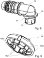
- Figures 6 to 9 show a second and third embodiment of the invention.
- the following specification of these further embodiments is limited to differences to the first embodiment of the invention.
- the skilled person is referred to the above specification of the first embodiment.
- the same reference signs are used for identical features of features having a similar effect in order to emphasize the similarities.
- an O-ring 22 is provided in a gap between the outer wall and the collar structure 16 to seal the connection between the snap-on module 18 and the sheet metal plate 10.
- the flange on the inside of the collar structure 16 can be dispensed with in this embodiment.
- Fig. 8 and 9 illustrate a spigot 12 and a snap-on module of a connector assembly according to the third embodiment of the invention the end portion of the spigot 12 to be inserted into the orifice 10b of the snap-on module 18 is provided with recesses 24 accommodating inwardly protruding end portions of a subset of latches 18b1 of the snap-on module 18.
- a second subset of latches 18b2 engages radially outward with the orifice 10a of the sheet metal plate 10 (not illustrated).
- the limited width of the recesses 24 in the circumferential direction define the relative rotational position of the spigot 12 and the snap-on module 18, which is further defined by mating structures 26, 26' on an upper surface of the snap-on module 18 and on a flange 28 of the spigot 12.
Landscapes
- Engineering & Computer Science (AREA)
- General Engineering & Computer Science (AREA)
- Mechanical Engineering (AREA)
- Physics & Mathematics (AREA)
- Thermal Sciences (AREA)
- Quick-Acting Or Multi-Walled Pipe Joints (AREA)
- Battery Mounting, Suspending (AREA)
- Secondary Cells (AREA)
- Connector Housings Or Holding Contact Members (AREA)
- Auxiliary Devices For And Details Of Packaging Control (AREA)
- Cooling Or The Like Of Electrical Apparatus (AREA)
- Endoscopes (AREA)
- Coupling Device And Connection With Printed Circuit (AREA)
Claims (13)
- Verbinderanordnung mit einer Metallplatte (10), die eine Öffnung (10a) und einen Leitungszapfen (12) aufweist, wobei der Leitungszapfen (12) einen inneren Strömungsweg für Flüssigkeit aufweist, und einer Verbindereinrichtung (14) zum Verbinden des Leitungszapfens (12) mit der Metallplatte (10), um die in dem Strömungsweg fließende Flüssigkeit durch die Öffnung (10a) zu leiten, wobei die Verbindereinrichtung (14) eine vorstehende Kragenstruktur (16) aufweist, die die Öffnung (10a) umgibt,wobei ein männliches Ende des Leitungszapfens (12) so konfiguriert ist, dass es in die Kragenstruktur (16) eingesetzt werden kann,wobeidie Verbindungsenrichtung (14) ferner ein ringförmiges Aufschnappmodul (18) umfasst, das so konfiguriert ist, dass es über der Kragenstruktur (16) angebracht werden kann, wobei das Aufschnappmodul (18) ein zylindrisches Einsetzteil (18a) umfasst, das so konfiguriert ist, dass es in die Öffnung (10a) der Kragenstruktur (16) eingesetzt werden kann, wobei ein distales Ende des zylindrischen Einsetzteils (18a) in der Einsetzrichtung mit ersten Schnappstrukturen versehen ist, die in die Kragenstruktur (16) eingreifen,dadurch gekennzeichnet, dassdie zylindrische Innenwand des Einsetzteils (18a) des ringförmigen Aufschnappmoduls (18) mit einer Kerbe versehen ist, die zur Aufnahme eines ersten O-Rings (20) ausgelegt ist.
- Verbinderanordnung nach Anspruch 1,
dadurch gekennzeichnet, dass
die Platte eine Blechplatte (10) ist und wobei die vorstehende Kragenstruktur (16) einstückig aus dem Blech der Blechplatte (10) durch ein Blechformverfahren hergestellt ist. - Verbinderanordnung nach einem der vorhergehenden Ansprüche,
dadurch gekennzeichnet, dass
ein Innenumfang der Kragenstruktur (16) eine Struktur aufweist, die so konfiguriert ist, dass sie einen O-Ring trägt, der zwischen der Kragenstruktur (16) und der Außenwand des Einsteckteils (18a) angeordnet wird. - Verbinderanordnung nach einem der vorhergehenden Ansprüche,
dadurch gekennzeichnet, dass
das ringförmige Aufschnappmodul (18) ferner eine Außenwand aufweist, die die Kragenstruktur (16) umgibt, und ein O-Ring (22) in einem Spalt zwischen der Außenwand und der Kragenstruktur (16) vorgesehen ist. - Verbinderanordnung nach einem der vorhergehenden Ansprüche,
dadurch gekennzeichnet, dass
das ringförmige Aufschnappmodul (18) ein Kunststoffteil ist. - Verbinderanordnung nach einem der vorhergehenden Ansprüche,
dadurch gekennzeichnet, dass
die Kragenstruktur (16) eine zylindrische Doppelschichtstruktur ist, wobei ein Rand an der radialen Innenseite der Kragenstruktur (16) auf einer der Öffnung (10a) zugewandten Seite angeordnet ist. - Verbinderanordnung nach den Ansprüchen 2 und 6,
dadurch gekennzeichnet, dass
die zylindrische Doppelschichtstruktur durch Zurückfalten des Blechs erhalten wird. - Verbinderanordnung nach einem der vorhergehenden Ansprüche,
dadurch gekennzeichnet, dass
das männliche Ende des Leitungszapfens (12) Verriegelungsstrukturen auf einer radialen Außenfläche seines Endabschnitts aufweist, wobei die Verriegelungsstrukturen so konfiguriert sind, dass sie mit entsprechenden Verriegelungsstrukturen auf einer zylindrischen Innenfläche der Verbindungseinrichtung (14) zusammenwirken. - Verbinderanordnung nach Anspruch 8,
dadurch gekennzeichnet, dass
die Verriegelungsstruktur an der radialen Außenfläche des Endabschnitts des Leitungszapfens (12) so konfiguriert ist, dass sie um einen Rand der zylindrischen Innenfläche der Verbindereinrichtung (14) herum in Eingriff tritt. - Verbinderanordnung nach einem der vorhergehenden Ansprüche,
dadurch gekennzeichnet, dass
die zylindrische Innenfläche der Verbindereinrichtung (14) eine zylindrische Innenfläche des ringförmigen Aufschnappmoduls (18) ist. - Verbinderanordnung nach einem der vorhergehenden Ansprüche,
dadurch gekennzeichnet, dass
die ersten Verriegelungsstrukturen so gestaltet sind, dass sie in einen unteren Rand der Kragenstruktur (16) eingreifen. - Verbinderanordnung nach einem der vorangehenden Ansprüche,
dadurch gekennzeichnet, dass
der Eingriff in der Einsteckrichtung mit ersten Verriegelungsstrukturen des zylindrischen Einsteckteils (18a) mit der Kragenstruktur (16) durch das Einstecken des männlichen Endes des Leitungszapfens (12) verriegelt wird. - Kühlsystem, insbesondere für Batteriebaugruppen, mit einer Verbinderanordnung nach einem der Ansprüche 1 bis 12.
Priority Applications (1)
| Application Number | Priority Date | Filing Date | Title |
|---|---|---|---|
| PL18815966.9T PL3887702T3 (pl) | 2018-11-29 | 2018-11-29 | Zespół złączki i układ chłodzenia zawierający taki zespół |
Applications Claiming Priority (1)
| Application Number | Priority Date | Filing Date | Title |
|---|---|---|---|
| PCT/EP2018/083067 WO2020108763A1 (en) | 2018-11-29 | 2018-11-29 | Connector assembly, plate for use with such an assembly and a cooling system including such an assembly |
Publications (3)
| Publication Number | Publication Date |
|---|---|
| EP3887702A1 EP3887702A1 (de) | 2021-10-06 |
| EP3887702C0 EP3887702C0 (de) | 2023-09-27 |
| EP3887702B1 true EP3887702B1 (de) | 2023-09-27 |
Family
ID=64664238
Family Applications (1)
| Application Number | Title | Priority Date | Filing Date |
|---|---|---|---|
| EP18815966.9A Active EP3887702B1 (de) | 2018-11-29 | 2018-11-29 | Verbinderanordnung und kühlsystem mit einer solchen anordnung |
Country Status (10)
| Country | Link |
|---|---|
| US (1) | US11927406B2 (de) |
| EP (1) | EP3887702B1 (de) |
| JP (1) | JP7213349B2 (de) |
| KR (1) | KR102587123B1 (de) |
| CN (1) | CN113167423B (de) |
| CA (1) | CA3118968C (de) |
| ES (1) | ES2967083T3 (de) |
| MX (1) | MX2021005562A (de) |
| PL (1) | PL3887702T3 (de) |
| WO (1) | WO2020108763A1 (de) |
Families Citing this family (8)
| Publication number | Priority date | Publication date | Assignee | Title |
|---|---|---|---|---|
| FR3086381B1 (fr) * | 2018-09-25 | 2022-05-20 | Valeo Systemes Thermiques | Adaptateur pour collecteur d'un echangeur de chaleur |
| DE102021119164A1 (de) * | 2021-07-23 | 2023-01-26 | Man Truck & Bus Se | Vorrichtung zur Kühlmittelversorgung eines elektrischen Energiespeichers |
| US11796105B2 (en) * | 2021-12-06 | 2023-10-24 | Cooper-Standard Automotive Inc. | Connector assembly for coupling a vessel to a fluid tube |
| FR3136544B1 (fr) | 2022-06-09 | 2024-06-28 | Valeo Systemes Thermiques | Système de connexion d’une entrée ou d’une sortie de fluide pour un échangeur de chaleur |
| EP4310431A1 (de) * | 2022-07-22 | 2024-01-24 | Valeo Systemes Thermiques | Thermische steuerungsvorrichtung, insbesondere zum kühlen eines elektrischen bauteils |
| FR3163721A1 (fr) * | 2024-06-25 | 2025-12-26 | Sogefi Air & Cooling | Dispositif destiné à contenir du liquide, du type contenant ou circuit de circulation, et procédés de fabrication de ce dispositif |
| DE102024131734A1 (de) * | 2024-10-30 | 2026-04-30 | Viega Technology Gmbh & Co. Kg | Wanddurchführung |
| CN121067147B (zh) * | 2025-11-06 | 2026-02-03 | 山西建筑工程集团有限公司 | 一种农村污水改造管道密封连接机构 |
Family Cites Families (18)
| Publication number | Priority date | Publication date | Assignee | Title |
|---|---|---|---|---|
| FR1322978A (fr) * | 1962-02-22 | 1963-04-05 | Chausson Usines Sa | Dispositif pour le raccordement d'une boîte à eau d'un échangeur de chaleur avec une tubulure, notamment une tubulure d'amenée de liquide |
| US4379574A (en) * | 1980-12-22 | 1983-04-12 | Ex-Cell-O Corporation | Radiator assembly (bayonet lock) |
| US4400020A (en) * | 1981-08-10 | 1983-08-23 | Keller Russell D | Pressure tank connector |
| JPS5877720A (ja) | 1981-10-31 | 1983-05-11 | Aisin Warner Ltd | 3重折りボス部付環状フランジ板の製造方法 |
| FR2577007B1 (fr) * | 1985-02-04 | 1987-05-15 | Commissariat Energie Atomique | Dispositif de fixation d'un tube sur une plaque a tubes |
| JPH0542893Y2 (de) * | 1987-09-08 | 1993-10-28 | ||
| US5131572A (en) * | 1990-09-24 | 1992-07-21 | Tolco Corporation | Jug and dispensing valve |
| US5368340A (en) * | 1993-03-18 | 1994-11-29 | Automotive Systems Technology, Inc. | Quick connect coupling |
| GB9703004D0 (en) * | 1997-02-13 | 1997-04-02 | Guest John Eng | Improvements in or relating to connectors for coupling tubes |
| US6612545B1 (en) * | 2000-04-12 | 2003-09-02 | David S. Smith Packaging Limited | Screw on connector |
| JP2002206892A (ja) * | 2000-12-28 | 2002-07-26 | Toyo Radiator Co Ltd | 熱交換器の出入口パイプ接続構造 |
| JP4680484B2 (ja) * | 2001-03-21 | 2011-05-11 | コンチネンタル・テベス・アーゲー・ウント・コンパニー・オーハーゲー | 所定の角をなした位置を有する接続部材を具備するブレーキサーボ |
| JP4588933B2 (ja) * | 2001-07-10 | 2010-12-01 | 株式会社ティラド | 樹脂製パイプとタンクとの接続構造 |
| JP2004100864A (ja) * | 2002-09-11 | 2004-04-02 | Tacmina Corp | 継手装置 |
| DE102004016051B4 (de) * | 2003-08-18 | 2014-08-28 | Continental Teves Ag & Co. Ohg | Bremskraftverstärker |
| JP2006226421A (ja) * | 2005-02-18 | 2006-08-31 | Tokai Rubber Ind Ltd | コネクタ取り付け構造 |
| DE102008036538A1 (de) * | 2008-08-06 | 2010-04-22 | Kautex Textron Gmbh & Co Kg | Kraftfahrzeug-Kraftstoffbehälter |
| DE202012102342U1 (de) * | 2012-06-26 | 2013-10-02 | Voss Automotive Gmbh | Anschlussvorrichtung für Rohrleitungen |
-
2018
- 2018-11-29 EP EP18815966.9A patent/EP3887702B1/de active Active
- 2018-11-29 MX MX2021005562A patent/MX2021005562A/es unknown
- 2018-11-29 ES ES18815966T patent/ES2967083T3/es active Active
- 2018-11-29 CA CA3118968A patent/CA3118968C/en active Active
- 2018-11-29 US US17/297,480 patent/US11927406B2/en active Active
- 2018-11-29 PL PL18815966.9T patent/PL3887702T3/pl unknown
- 2018-11-29 KR KR1020217019625A patent/KR102587123B1/ko active Active
- 2018-11-29 WO PCT/EP2018/083067 patent/WO2020108763A1/en not_active Ceased
- 2018-11-29 JP JP2021530263A patent/JP7213349B2/ja active Active
- 2018-11-29 CN CN201880099812.2A patent/CN113167423B/zh active Active
Also Published As
| Publication number | Publication date |
|---|---|
| PL3887702T3 (pl) | 2024-03-11 |
| KR20210091814A (ko) | 2021-07-22 |
| EP3887702C0 (de) | 2023-09-27 |
| JP2022514204A (ja) | 2022-02-10 |
| US11927406B2 (en) | 2024-03-12 |
| CN113167423B (zh) | 2023-09-26 |
| BR112021008856A2 (pt) | 2021-08-31 |
| KR102587123B1 (ko) | 2023-10-16 |
| WO2020108763A1 (en) | 2020-06-04 |
| CN113167423A (zh) | 2021-07-23 |
| ES2967083T3 (es) | 2024-04-25 |
| US20220003510A1 (en) | 2022-01-06 |
| MX2021005562A (es) | 2021-07-02 |
| EP3887702A1 (de) | 2021-10-06 |
| JP7213349B2 (ja) | 2023-01-26 |
| CA3118968C (en) | 2024-01-02 |
| CA3118968A1 (en) | 2020-06-04 |
Similar Documents
| Publication | Publication Date | Title |
|---|---|---|
| US11927406B2 (en) | Connector assembly, plate for use with such an assembly and a cooling system including such an assembly | |
| EP3887701B1 (de) | Anschlussbuchse, verbinderanordnung, kühlplatte und kühlsystem mit der anschlussbuchse | |
| US10865922B2 (en) | Anti-tamper permanent quick connect coupling device | |
| US11014441B2 (en) | Closure assembly for fuel-tank filler neck | |
| CN102989082A (zh) | 管连接器 | |
| JP2003227581A (ja) | コネクタ用半嵌合防止クリップ | |
| CN107588256A (zh) | 塑料密封配件 | |
| US6805383B2 (en) | Fluid quick connector with secure electrical contact | |
| CN108139005A (zh) | 用于连接用于液态介质或气态介质的管道的插塞连接器 | |
| EP0657005A4 (de) | Abgabeventil. | |
| US11796105B2 (en) | Connector assembly for coupling a vessel to a fluid tube | |
| US20050110273A1 (en) | Device for the coaxial connection of two manifolds | |
| CN108119715B (zh) | 插接式连接装置以及连接或分离该插接式连接装置的方法 | |
| RU2773766C1 (ru) | Соединительный узел и система охлаждения, содержащая такой узел | |
| RU2773858C1 (ru) | Соединительное гнездо, соединительный узел и система охлаждения, содержащая соединительное гнездо | |
| BR112021008856B1 (pt) | Montagem de conector, e sistema de refrigeração incluindo tal montagem | |
| JP2019015300A (ja) | 流体機器の接続構造 |
Legal Events
| Date | Code | Title | Description |
|---|---|---|---|
| STAA | Information on the status of an ep patent application or granted ep patent |
Free format text: STATUS: UNKNOWN |
|
| STAA | Information on the status of an ep patent application or granted ep patent |
Free format text: STATUS: THE INTERNATIONAL PUBLICATION HAS BEEN MADE |
|
| PUAI | Public reference made under article 153(3) epc to a published international application that has entered the european phase |
Free format text: ORIGINAL CODE: 0009012 |
|
| STAA | Information on the status of an ep patent application or granted ep patent |
Free format text: STATUS: REQUEST FOR EXAMINATION WAS MADE |
|
| 17P | Request for examination filed |
Effective date: 20210511 |
|
| AK | Designated contracting states |
Kind code of ref document: A1 Designated state(s): AL AT BE BG CH CY CZ DE DK EE ES FI FR GB GR HR HU IE IS IT LI LT LU LV MC MK MT NL NO PL PT RO RS SE SI SK SM TR |
|
| DAV | Request for validation of the european patent (deleted) | ||
| DAX | Request for extension of the european patent (deleted) | ||
| GRAP | Despatch of communication of intention to grant a patent |
Free format text: ORIGINAL CODE: EPIDOSNIGR1 |
|
| STAA | Information on the status of an ep patent application or granted ep patent |
Free format text: STATUS: GRANT OF PATENT IS INTENDED |
|
| INTG | Intention to grant announced |
Effective date: 20230511 |
|
| GRAS | Grant fee paid |
Free format text: ORIGINAL CODE: EPIDOSNIGR3 |
|
| GRAA | (expected) grant |
Free format text: ORIGINAL CODE: 0009210 |
|
| STAA | Information on the status of an ep patent application or granted ep patent |
Free format text: STATUS: THE PATENT HAS BEEN GRANTED |
|
| AK | Designated contracting states |
Kind code of ref document: B1 Designated state(s): AL AT BE BG CH CY CZ DE DK EE ES FI FR GB GR HR HU IE IS IT LI LT LU LV MC MK MT NL NO PL PT RO RS SE SI SK SM TR |
|
| REG | Reference to a national code |
Ref country code: GB Ref legal event code: FG4D |
|
| REG | Reference to a national code |
Ref country code: CH Ref legal event code: EP |
|
| REG | Reference to a national code |
Ref country code: DE Ref legal event code: R096 Ref document number: 602018058375 Country of ref document: DE |
|
| REG | Reference to a national code |
Ref country code: IE Ref legal event code: FG4D |
|
| U01 | Request for unitary effect filed |
Effective date: 20231026 |
|
| U07 | Unitary effect registered |
Designated state(s): AT BE BG DE DK EE FI FR IT LT LU LV MT NL PT SE SI Effective date: 20231031 |
|
| U20 | Renewal fee for the european patent with unitary effect paid |
Year of fee payment: 6 Effective date: 20231121 |
|
| PG25 | Lapsed in a contracting state [announced via postgrant information from national office to epo] |
Ref country code: GR Free format text: LAPSE BECAUSE OF FAILURE TO SUBMIT A TRANSLATION OF THE DESCRIPTION OR TO PAY THE FEE WITHIN THE PRESCRIBED TIME-LIMIT Effective date: 20231228 |
|
| PG25 | Lapsed in a contracting state [announced via postgrant information from national office to epo] |
Ref country code: RS Free format text: LAPSE BECAUSE OF FAILURE TO SUBMIT A TRANSLATION OF THE DESCRIPTION OR TO PAY THE FEE WITHIN THE PRESCRIBED TIME-LIMIT Effective date: 20230927 Ref country code: NO Free format text: LAPSE BECAUSE OF FAILURE TO SUBMIT A TRANSLATION OF THE DESCRIPTION OR TO PAY THE FEE WITHIN THE PRESCRIBED TIME-LIMIT Effective date: 20231227 Ref country code: GR Free format text: LAPSE BECAUSE OF FAILURE TO SUBMIT A TRANSLATION OF THE DESCRIPTION OR TO PAY THE FEE WITHIN THE PRESCRIBED TIME-LIMIT Effective date: 20231228 |
|
| PG25 | Lapsed in a contracting state [announced via postgrant information from national office to epo] |
Ref country code: IS Free format text: LAPSE BECAUSE OF FAILURE TO SUBMIT A TRANSLATION OF THE DESCRIPTION OR TO PAY THE FEE WITHIN THE PRESCRIBED TIME-LIMIT Effective date: 20240127 |
|
| REG | Reference to a national code |
Ref country code: ES Ref legal event code: FG2A Ref document number: 2967083 Country of ref document: ES Kind code of ref document: T3 Effective date: 20240425 |
|
| PG25 | Lapsed in a contracting state [announced via postgrant information from national office to epo] |
Ref country code: SM Free format text: LAPSE BECAUSE OF FAILURE TO SUBMIT A TRANSLATION OF THE DESCRIPTION OR TO PAY THE FEE WITHIN THE PRESCRIBED TIME-LIMIT Effective date: 20230927 Ref country code: RO Free format text: LAPSE BECAUSE OF FAILURE TO SUBMIT A TRANSLATION OF THE DESCRIPTION OR TO PAY THE FEE WITHIN THE PRESCRIBED TIME-LIMIT Effective date: 20230927 Ref country code: IS Free format text: LAPSE BECAUSE OF FAILURE TO SUBMIT A TRANSLATION OF THE DESCRIPTION OR TO PAY THE FEE WITHIN THE PRESCRIBED TIME-LIMIT Effective date: 20240127 Ref country code: CZ Free format text: LAPSE BECAUSE OF FAILURE TO SUBMIT A TRANSLATION OF THE DESCRIPTION OR TO PAY THE FEE WITHIN THE PRESCRIBED TIME-LIMIT Effective date: 20230927 Ref country code: SK Free format text: LAPSE BECAUSE OF FAILURE TO SUBMIT A TRANSLATION OF THE DESCRIPTION OR TO PAY THE FEE WITHIN THE PRESCRIBED TIME-LIMIT Effective date: 20230927 |
|
| REG | Reference to a national code |
Ref country code: DE Ref legal event code: R097 Ref document number: 602018058375 Country of ref document: DE |
|
| PG25 | Lapsed in a contracting state [announced via postgrant information from national office to epo] |
Ref country code: MC Free format text: LAPSE BECAUSE OF FAILURE TO SUBMIT A TRANSLATION OF THE DESCRIPTION OR TO PAY THE FEE WITHIN THE PRESCRIBED TIME-LIMIT Effective date: 20230927 |
|
| PG25 | Lapsed in a contracting state [announced via postgrant information from national office to epo] |
Ref country code: MC Free format text: LAPSE BECAUSE OF FAILURE TO SUBMIT A TRANSLATION OF THE DESCRIPTION OR TO PAY THE FEE WITHIN THE PRESCRIBED TIME-LIMIT Effective date: 20230927 |
|
| PLBE | No opposition filed within time limit |
Free format text: ORIGINAL CODE: 0009261 |
|
| STAA | Information on the status of an ep patent application or granted ep patent |
Free format text: STATUS: NO OPPOSITION FILED WITHIN TIME LIMIT |
|
| 26N | No opposition filed |
Effective date: 20240628 |
|
| REG | Reference to a national code |
Ref country code: IE Ref legal event code: MM4A |
|
| PG25 | Lapsed in a contracting state [announced via postgrant information from national office to epo] |
Ref country code: IE Free format text: LAPSE BECAUSE OF NON-PAYMENT OF DUE FEES Effective date: 20231129 |
|
| PG25 | Lapsed in a contracting state [announced via postgrant information from national office to epo] |
Ref country code: IE Free format text: LAPSE BECAUSE OF NON-PAYMENT OF DUE FEES Effective date: 20231129 |
|
| U20 | Renewal fee for the european patent with unitary effect paid |
Year of fee payment: 7 Effective date: 20241129 |
|
| PG25 | Lapsed in a contracting state [announced via postgrant information from national office to epo] |
Ref country code: HR Free format text: LAPSE BECAUSE OF FAILURE TO SUBMIT A TRANSLATION OF THE DESCRIPTION OR TO PAY THE FEE WITHIN THE PRESCRIBED TIME-LIMIT Effective date: 20230927 |
|
| PG25 | Lapsed in a contracting state [announced via postgrant information from national office to epo] |
Ref country code: CY Free format text: LAPSE BECAUSE OF FAILURE TO SUBMIT A TRANSLATION OF THE DESCRIPTION OR TO PAY THE FEE WITHIN THE PRESCRIBED TIME-LIMIT; INVALID AB INITIO Effective date: 20181129 |
|
| PG25 | Lapsed in a contracting state [announced via postgrant information from national office to epo] |
Ref country code: HU Free format text: LAPSE BECAUSE OF FAILURE TO SUBMIT A TRANSLATION OF THE DESCRIPTION OR TO PAY THE FEE WITHIN THE PRESCRIBED TIME-LIMIT; INVALID AB INITIO Effective date: 20181129 |
|
| REG | Reference to a national code |
Ref country code: CH Ref legal event code: U11 Free format text: ST27 STATUS EVENT CODE: U-0-0-U10-U11 (AS PROVIDED BY THE NATIONAL OFFICE) Effective date: 20251201 |
|
| U20 | Renewal fee for the european patent with unitary effect paid |
Year of fee payment: 8 Effective date: 20251125 |
|
| PGFP | Annual fee paid to national office [announced via postgrant information from national office to epo] |
Ref country code: GB Payment date: 20251125 Year of fee payment: 8 |
|
| PGFP | Annual fee paid to national office [announced via postgrant information from national office to epo] |
Ref country code: TR Payment date: 20251110 Year of fee payment: 8 |
|
| PGFP | Annual fee paid to national office [announced via postgrant information from national office to epo] |
Ref country code: CH Payment date: 20251201 Year of fee payment: 8 |
|
| PGFP | Annual fee paid to national office [announced via postgrant information from national office to epo] |
Ref country code: PL Payment date: 20251104 Year of fee payment: 8 |
|
| PGFP | Annual fee paid to national office [announced via postgrant information from national office to epo] |
Ref country code: ES Payment date: 20251209 Year of fee payment: 8 |