EP3887733B1 - Procédé et appareil de démarrage séquencé d'un système de réfrigération à l'ammoniac conditionné à basse charge refroidie par air - Google Patents
Procédé et appareil de démarrage séquencé d'un système de réfrigération à l'ammoniac conditionné à basse charge refroidie par air Download PDFInfo
- Publication number
- EP3887733B1 EP3887733B1 EP19888679.8A EP19888679A EP3887733B1 EP 3887733 B1 EP3887733 B1 EP 3887733B1 EP 19888679 A EP19888679 A EP 19888679A EP 3887733 B1 EP3887733 B1 EP 3887733B1
- Authority
- EP
- European Patent Office
- Prior art keywords
- refrigerant
- condenser
- compressor
- vapor
- refrigeration system
- Prior art date
- Legal status (The legal status is an assumption and is not a legal conclusion. Google has not performed a legal analysis and makes no representation as to the accuracy of the status listed.)
- Active
Links
Images


Classifications
-
- F—MECHANICAL ENGINEERING; LIGHTING; HEATING; WEAPONS; BLASTING
- F25—REFRIGERATION OR COOLING; COMBINED HEATING AND REFRIGERATION SYSTEMS; HEAT PUMP SYSTEMS; MANUFACTURE OR STORAGE OF ICE; LIQUEFACTION SOLIDIFICATION OF GASES
- F25B—REFRIGERATION MACHINES, PLANTS OR SYSTEMS; COMBINED HEATING AND REFRIGERATION SYSTEMS; HEAT PUMP SYSTEMS
- F25B43/00—Arrangements for separating or purifying gases or liquids; Arrangements for vaporising the residuum of liquid refrigerant, e.g. by heat
- F25B43/02—Arrangements for separating or purifying gases or liquids; Arrangements for vaporising the residuum of liquid refrigerant, e.g. by heat for separating lubricants from the refrigerant
-
- F—MECHANICAL ENGINEERING; LIGHTING; HEATING; WEAPONS; BLASTING
- F25—REFRIGERATION OR COOLING; COMBINED HEATING AND REFRIGERATION SYSTEMS; HEAT PUMP SYSTEMS; MANUFACTURE OR STORAGE OF ICE; LIQUEFACTION SOLIDIFICATION OF GASES
- F25B—REFRIGERATION MACHINES, PLANTS OR SYSTEMS; COMBINED HEATING AND REFRIGERATION SYSTEMS; HEAT PUMP SYSTEMS
- F25B41/00—Fluid-circulation arrangements
- F25B41/20—Disposition of valves, e.g. of on-off valves or flow control valves
-
- F—MECHANICAL ENGINEERING; LIGHTING; HEATING; WEAPONS; BLASTING
- F25—REFRIGERATION OR COOLING; COMBINED HEATING AND REFRIGERATION SYSTEMS; HEAT PUMP SYSTEMS; MANUFACTURE OR STORAGE OF ICE; LIQUEFACTION SOLIDIFICATION OF GASES
- F25B—REFRIGERATION MACHINES, PLANTS OR SYSTEMS; COMBINED HEATING AND REFRIGERATION SYSTEMS; HEAT PUMP SYSTEMS
- F25B41/00—Fluid-circulation arrangements
- F25B41/40—Fluid line arrangements
-
- F—MECHANICAL ENGINEERING; LIGHTING; HEATING; WEAPONS; BLASTING
- F25—REFRIGERATION OR COOLING; COMBINED HEATING AND REFRIGERATION SYSTEMS; HEAT PUMP SYSTEMS; MANUFACTURE OR STORAGE OF ICE; LIQUEFACTION SOLIDIFICATION OF GASES
- F25B—REFRIGERATION MACHINES, PLANTS OR SYSTEMS; COMBINED HEATING AND REFRIGERATION SYSTEMS; HEAT PUMP SYSTEMS
- F25B49/00—Arrangement or mounting of control or safety devices
- F25B49/02—Arrangement or mounting of control or safety devices for compression type machines, plants or systems
- F25B49/027—Condenser control arrangements
-
- F—MECHANICAL ENGINEERING; LIGHTING; HEATING; WEAPONS; BLASTING
- F25—REFRIGERATION OR COOLING; COMBINED HEATING AND REFRIGERATION SYSTEMS; HEAT PUMP SYSTEMS; MANUFACTURE OR STORAGE OF ICE; LIQUEFACTION SOLIDIFICATION OF GASES
- F25B—REFRIGERATION MACHINES, PLANTS OR SYSTEMS; COMBINED HEATING AND REFRIGERATION SYSTEMS; HEAT PUMP SYSTEMS
- F25B2400/00—Component parts or details not otherwise provided for in this subclass
- F25B2400/04—Refrigeration circuit bypassing means
- F25B2400/0401—Refrigeration circuit bypassing means for compressors
-
- F—MECHANICAL ENGINEERING; LIGHTING; HEATING; WEAPONS; BLASTING
- F25—REFRIGERATION OR COOLING; COMBINED HEATING AND REFRIGERATION SYSTEMS; HEAT PUMP SYSTEMS; MANUFACTURE OR STORAGE OF ICE; LIQUEFACTION SOLIDIFICATION OF GASES
- F25B—REFRIGERATION MACHINES, PLANTS OR SYSTEMS; COMBINED HEATING AND REFRIGERATION SYSTEMS; HEAT PUMP SYSTEMS
- F25B2400/00—Component parts or details not otherwise provided for in this subclass
- F25B2400/13—Economisers
-
- F—MECHANICAL ENGINEERING; LIGHTING; HEATING; WEAPONS; BLASTING
- F25—REFRIGERATION OR COOLING; COMBINED HEATING AND REFRIGERATION SYSTEMS; HEAT PUMP SYSTEMS; MANUFACTURE OR STORAGE OF ICE; LIQUEFACTION SOLIDIFICATION OF GASES
- F25B—REFRIGERATION MACHINES, PLANTS OR SYSTEMS; COMBINED HEATING AND REFRIGERATION SYSTEMS; HEAT PUMP SYSTEMS
- F25B2500/00—Problems to be solved
- F25B2500/26—Problems to be solved characterised by the startup of the refrigeration cycle
-
- F—MECHANICAL ENGINEERING; LIGHTING; HEATING; WEAPONS; BLASTING
- F25—REFRIGERATION OR COOLING; COMBINED HEATING AND REFRIGERATION SYSTEMS; HEAT PUMP SYSTEMS; MANUFACTURE OR STORAGE OF ICE; LIQUEFACTION SOLIDIFICATION OF GASES
- F25B—REFRIGERATION MACHINES, PLANTS OR SYSTEMS; COMBINED HEATING AND REFRIGERATION SYSTEMS; HEAT PUMP SYSTEMS
- F25B2600/00—Control issues
- F25B2600/02—Compressor control
- F25B2600/027—Compressor control by controlling pressure
- F25B2600/0271—Compressor control by controlling pressure the discharge pressure
-
- F—MECHANICAL ENGINEERING; LIGHTING; HEATING; WEAPONS; BLASTING
- F25—REFRIGERATION OR COOLING; COMBINED HEATING AND REFRIGERATION SYSTEMS; HEAT PUMP SYSTEMS; MANUFACTURE OR STORAGE OF ICE; LIQUEFACTION SOLIDIFICATION OF GASES
- F25B—REFRIGERATION MACHINES, PLANTS OR SYSTEMS; COMBINED HEATING AND REFRIGERATION SYSTEMS; HEAT PUMP SYSTEMS
- F25B2600/00—Control issues
- F25B2600/25—Control of valves
- F25B2600/2519—On-off valves
-
- F—MECHANICAL ENGINEERING; LIGHTING; HEATING; WEAPONS; BLASTING
- F25—REFRIGERATION OR COOLING; COMBINED HEATING AND REFRIGERATION SYSTEMS; HEAT PUMP SYSTEMS; MANUFACTURE OR STORAGE OF ICE; LIQUEFACTION SOLIDIFICATION OF GASES
- F25B—REFRIGERATION MACHINES, PLANTS OR SYSTEMS; COMBINED HEATING AND REFRIGERATION SYSTEMS; HEAT PUMP SYSTEMS
- F25B5/00—Compression machines, plants or systems, with several evaporator circuits, e.g. for varying refrigerating capacity
- F25B5/02—Compression machines, plants or systems, with several evaporator circuits, e.g. for varying refrigerating capacity arranged in parallel
-
- F—MECHANICAL ENGINEERING; LIGHTING; HEATING; WEAPONS; BLASTING
- F25—REFRIGERATION OR COOLING; COMBINED HEATING AND REFRIGERATION SYSTEMS; HEAT PUMP SYSTEMS; MANUFACTURE OR STORAGE OF ICE; LIQUEFACTION SOLIDIFICATION OF GASES
- F25B—REFRIGERATION MACHINES, PLANTS OR SYSTEMS; COMBINED HEATING AND REFRIGERATION SYSTEMS; HEAT PUMP SYSTEMS
- F25B6/00—Compression machines, plants or systems, with several condenser circuits
- F25B6/02—Compression machines, plants or systems, with several condenser circuits arranged in parallel
Definitions
- the present invention relates to ammonia refrigeration systems; methods for start-up of ammonia refrigeration systems; and methods for modifying ammonia refrigeration systems.
- Chlorofluorocarbon refrigerant (CFC, HFC, HCFC) systems have utilized isolating valves on the outlet of condenser coils, which force liquid to back up in the condenser, reducing the surface area of the coil that is capable of condensing vapor.
- CFC, HFC, HCFC Chlorofluorocarbon refrigerant
- the present invention overcomes the problems of the prior art by allowing the condenser coils to isolate individually during the startup period, allowing individual sequencing of the coils until the condenser is warm enough to maintain discharge and oil pressure.
- This invention also eliminates the need for a stand-alone oil pump to maintain oil pressure during start-up.
- a refrigeration system according to the invention is defined in independent claim 1; a method for start-up of an air-cooled low charged packaged ammonia refrigeration system according to the invention is defined in independent claim 10; and a method for modifying an air-cooled low charged packaged ammonia refrigeration system according to the invention is defined in independent claim 11.
- Optional features of the invention are defined in the dependent claims.
- Motorized valves can be installed on all or one of the condenser coil inlets, a main compressor discharge motorized valve is installed, a bypass pressure regulator valve in the main compressor piping is installed, check valves on the condenser outlets are installed and speed control of the condenser fans.
- the condenser inlet motorized valves provide precise control of gas feed or act as an on/off valve for the condensers allowing pressure to build without collapsing the oil pressure.
- the motorized valves provide precise control of the gas flow at a very low pressure drop or provide on/off control as needed.
- the air-cooled condensers may be any style: tube and fin or microchannel, etc.
- the condenser coil outlet contains vertically-oriented inline check valves to prevent liquid backflow when a coil is isolated. This allows each condenser coil to be isolated without trapping significant liquid refrigerant charge in a low-charge ammonia, refrigeration system. Trapping an appreciable amount of liquid in the condenser coils upsets startup of a packaged ammonia refrigeration system.
- the compressor discharge line contains a single motorized valve for regulating discharge pressure. The motorized valve is used for coarse gas control at start-up.
- the motorized valve in the compressor discharge piping also includes a bypass with a mechanical pressure regulator to allow precise regulation at the minimum discharge pressure.
- the condenser inlet solenoid coils will open one at a time.
- the discharge pressure regulating motorized valve will simultaneously regulate the discharge pressure until the condenser coil has warmed up enough to maintain discharge pressure.
- Fan speed control is also utilized to maintain stable operation at start-up.
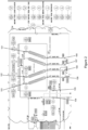
- Figure 1 is a process and instrumentation diagram for a single compressor, air-cooled (non-evaporative) condenser, low charge packaged penthouse refrigeration system according to an embodiment of the invention.
- Figure 2 A blow-up of the upper right quadrant of Figure 1 is presented in Figure 2 .
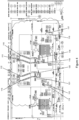
- Figure 3 is a process and instrumentation diagram for a dual compressor, air-cooled condenser, low charge packaged penthouse refrigeration system according to an embodiment of the invention.
- a blow-up of the upper right quadrant of Figure 3 is presented in Figure 4 .
- the system includes evaporators 2a and 2b, including evaporator coils 4a and 4b, respectively, condenser 8, compressor(s) 10, expansion devices 11a and 11b (which may be provided in the form of valves, metering orifices or other expansion devices), pump 16, liquid-vapor separation device 12, and economizer 14.
- liquid-vapor separation device 12 may be a recirculator vessel.
- liquid-vapor separation device 12 and economizer 14 may one or both provided in the form of single or dual phase cyclonic separators.
- the foregoing elements may be connected using standard refrigerant tubing in the manner shown in Figures 1-4 .
- the term "connected to" or “connected via” means connected directly or indirectly, unless otherwise stated.
- low pressure liquid refrigerant is supplied to the evaporator by pump 16 via expansion devices 11.
- the refrigerant accepts heat from the refrigerated space, leaves the evaporator as low pressure vapor (“LPV”) and liquid and is delivered to the liquid-vapor separation device 12 (which may optionally be a cyclonic separator) which separates the liquid from the vapor.
- Liquid refrigerant is returned to the pump 16, and the vapor (“LPV”) is delivered to the compressor 10 which condenses the vapor and sends high pressure vapor (“HPV”) to the condenser 8 which compresses it to high pressure liquid (“HPL").
- HPL is delivered to the economizer 14 which improves system efficiency by reducing the high pressure liquid (“HPL”) to intermediate pressure liquid (“IPL”) then delivers it to the liquid-vapor separation device 12, which supplies the pump 16 with low pressure liquid refrigerant (“LPL”), completing the refrigerant cycle.
- HPL high pressure liquid
- IPL intermediate pressure liquid
- LPL low pressure liquid refrigerant
- Figures 1-4 also include numerous control, isolation, and safety valves, as well as temperature and pressure sensors (a.k.a. indicators or gages) for monitoring and control of the system.
- motorized condenser inlet 101, 102 and 103 valves are installed on the inlet of the condenser coil bundles.
- the motorized valves can function as variable control valves or on/off valves.
- valves 101, 102 and 103 will begin to open. Once all valves are open, variable fan control takes over pressure control.
- the sequencing of the use of valves and fan operation can vary, based on system operation and design.
- Motorized valve 104 and ammonia pressure regulator valve 105 provide precise ammonia gas control during start-up of the system in low ambient conditions. During start-up, all motorized valves are closed and the pressure regulator provides compressor differential pressure control to ensure proper oil flow. The ammonia pressure regulator 105 provides low volume flow control. As the compressor begins to load, more ammonia gas flow is generated. Motorized valve 104 begins to open and control the discharge pressure, compressor differential pressure and oil flow.
- the next step during system start-up is to begin opening the condenser motorized valves 101, 102 and 103 and concomitant staging the startup of the condenser fans.
- Check valves 106, 107, 108 and 109 installed at the outlet to the condenser bundles are utilized to ensure liquid ammonia does not backflow into the condenser or other coil bundles during periods of downtime or normal operating periods.
- valves 101, 102, 103 and 105 are activated by attached microcontrollers or PLC (programmable logic control).
- PLC programmable logic control
- a central microcontroller or PLC monitors the status of each valve, as well as discharge pressure, and directs the action of the valves accordingly for sequential startup of the condenser coils while maintaining gas and oil pressure.
- valves are required for a every ambient condition. In fact, above a certain ambient temperature, low ambient control may not be required. Therefore, valves can be installed and arranged to optimize operation at startup based on the ambient temperature.
- Figures 3 and 4 show a process and instrumentation diagram for a dual compressor, air-cooled condenser, low charge packaged penthouse refrigeration system.
- the dual compressor design utilizes and isolated compressor concept.
- the compressors use different oil separators, oil coolers, and condenser bundles.
- Motorized valves 110, 111, 112 and 113 are installed on the inlet of the condenser coil bundles.
- the motorized valves can function as variable control valves or on/off valves.
- valves 111and 112 During startup, motorized valves 111and 112 will be opened to a minimum position to allow ammonia gas flow to the condenser coil. As the system begins increasing load, valves 111 and 112 will open to 100% and valves 113 and 110 will begin opening. Once all valves are open, variable fan control takes over pressure control. The sequencing of the use of valves and fan operation can vary, based on system operation and design.
- Fine ammonia gas control during start-up of the system is provided by:
- the next stage is to begin opening the condenser motorized valves (110, 111, 112 and 113) and staging the condenser fans accordingly.
- Check valves (118, 119, 120 and 121) are utilized to ensure liquid ammonia does not backflow into the condenser or other coil bundles during periods of downtime or normal operating periods.
- each of valves 110-117 is activated by attached microcontrollers or PLC.
- a central microcontroller or PLC monitors the status of each valve, as well as discharge pressure, and directs the action of the valves accordingly for sequential startup of the condenser coils while maintaining gas and oil pressure. Not all valves are required for every ambient condition. In fact, above a certain ambient temperature, low ambient control may not be required. Therefore, valves can be installed and arranged to optimize operation at startup based on the ambient temperature.
- the evaporator is housed in the evaporator (penthouse) module, and the remaining components of the system shown in Figures 1-4 (except for the condenser coils and fans and associated structures) are housed in an enclosure such as a machine room module.
- the condenser coils and fans may be mounted on top of the enclosure or machine room module for a complete self-contained rooftop system.
- the air-cooled condenser may optionally be fitted with an adiabatic air pre-cooling system.
- the entire system may be completely self-contained in two roof-top modules making it very easy for over-the-road transport to the install site, using e.g., flat bed permit load non-escort vehicles.
- the penthouse and machine room modules can be separated for shipping and/or for final placement, but according to most preferred embodiments, the penthouse and machine room modules are mounted adjacent to one-another to maximize the reduction in refrigerant charge. According to a most preferred embodiment, the penthouse module and the machine room module are integrated into a single module, although the evaporator space is separated and insulated from the machine room space to comply with industry codes. According to an alternative embodiment, the evaporator coil may be mounted in a refrigerated space adjacent to, below, or remote from, the machine room module.
Landscapes
- Engineering & Computer Science (AREA)
- Physics & Mathematics (AREA)
- Mechanical Engineering (AREA)
- Thermal Sciences (AREA)
- General Engineering & Computer Science (AREA)
- Chemical & Material Sciences (AREA)
- Analytical Chemistry (AREA)
- Power Engineering (AREA)
- Devices That Are Associated With Refrigeration Equipment (AREA)
- Sorption Type Refrigeration Machines (AREA)
Claims (12)
- Système de réfrigération comprenant :un serpentin d'évaporateur de réfrigérant (4a ; 4b),une structure de séparation vapeur/liquide (12) reliée à une sortie dudit serpentin d'évaporateur par l'intermédiaire d'une conduite de réfrigérant configurée pour séparer une vapeur de réfrigérant basse pression à partir d'un liquide réfrigérant basse pression ;un compresseur de réfrigérant (10) relié à une sortie dudit dispositif de séparation liquide-vapeur par l'intermédiaire de la conduite de réfrigérant et configuré pour comprimer une vapeur de réfrigérant à partir de ladite structure de séparation vapeur-liquide ;une vanne motorisée de refoulement de compresseur (104) reliée à une sortie dudit compresseur de réfrigérant par l'intermédiaire de la conduite de réfrigérant et configurée pour une régulation approximative d'une pression de refoulement lors du démarrage de système ;une vanne de régulation de pression de dérivation (105) reliée à une sortie dudit compresseur de réfrigérant par l'intermédiaire de la conduite de réfrigérant et configurée pour une régulation précise de la pression de refoulement pendant le démarrage ; un condenseur de réfrigérant refroidi par air (8) comprenant une pluralité de serpentins de condenseur reliés à ladite vanne motorisée de refoulement de compresseur et à ladite vanne de régulation de pression de dérivation par l'intermédiaire de la conduite de réfrigérant et configurés pour condenser la vapeur de réfrigérant produite dans ledit compresseur en liquide réfrigérant,une vanne motorisée (101 ; 102 ; 103) reliée à une entrée d'au moins un desdits serpentins de condenseur configurée pour fournir une commande d'alimentation en gaz au serpentin de condenseur pour permettre à la pression de monter sans effondrement de la pression d'huile ;une vanne d'arrêt en ligne orienté verticalement (106 ; 107 ; 108 ; 109) reliée à une sortie d'au moins un desdits serpentins de condenseur configuré pour empêcher un reflux de liquide ;un récipient de collecte (14) relié à une sortie dudit condenseur par l'intermédiaire d'une conduite de réfrigérant pour recevoir le liquide réfrigérant à partir dudit condenseur ;la conduite de réfrigérant reliant une sortie dudit récipient de collecte à une entrée de ladite structure de séparation vapeur/liquide et configurée pour délivrer du liquide réfrigérant à ladite structure de séparation ;ladite structure de séparation vapeur/liquide ayant une sortie de liquide qui est reliée par l'intermédiaire de la conduite de réfrigérant à une entrée dudit serpentin d'évaporateur ;une enceinte modulaire pré-conditionnée ;et dans lequel ladite structure de séparation vapeur/liquide, ledit compresseur et ledit récipient de collecte sont situés à l'intérieur de l'enceinte modulaire pré-conditionnée.
- Système de réfrigération selon la revendication 1, comprenant en outre un réfrigérant, dans lequel ledit réfrigérant est de l'ammoniac.
- Système de réfrigération selon la revendication 1, dans lequel ladite structure de séparation vapeur/liquide (12) comprend un récipient de recirculation.
- Système de réfrigération selon la revendication 1, dans lequel ledit récipient de collecte (14) comprend un économiseur.
- Système de réfrigération selon la revendication 1, comprenant en outre un récipient séparateur d'huile configuré pour séparer l'huile de compresseur à partir de la vapeur de réfrigérant reçue à partir dudit compresseur de réfrigérant (10).
- Système de réfrigération selon la revendication 1, dans lequel ledit condenseur de réfrigérant refroidi par air (8) comprend des soufflantes de condenseur et est situé au-dessus de ladite enceinte modulaire pré-conditionnée ou adjacent à celle-ci.
- Système de réfrigération selon la revendication 1, dans lequel ledit condenseur de réfrigérant refroidi par air (8) comprend un système de pré-refroidissement d'air adiabatique.
- Système de réfrigération selon la revendication 1, comprenant en outre une salle d'évaporateur modulaire préfabriquée dans lequel ledit serpentin d'évaporateur de réfrigérant (4a ; 4b) est monté dans la salle d'évaporateur modulaire préfabriquée.
- Système de réfrigération selon la revendication 1, comprenant en outre un espace réfrigéré dans lequel ledit serpentin d'évaporateur de réfrigérant (4a ; 4b) est monté dans l'espace réfrigéré adjacent à ladite enceinte modulaire préfabriquée ou au-dessous de celle-ci.
- Procédé de démarrage d'un système de réfrigération à l'ammoniac conditionné à basse charge refroidie par air, ayant un évaporateur, un séparateur liquide/vapeur (12), un compresseur (10), un condenseur refroidi par air (8) ayant plusieurs serpentins de condenseur et un récipient de collecte (14), sans nécessiter de pompe à huile autonome pour maintenir la pression d'huile pendant le démarrage, ledit procédé comprenant :un démarrage de flux de réfrigérant à travers lesdits serpentins de condenseur un à la fois jusqu'à ce que chaque serpentin de condenseur soit suffisamment chaud pour maintenir la pression de refoulement et d'huile ;l'utilisation d'une vanne motorisée dans une conduite de refoulement à partir dudit compresseur pour une commande de course de flux de gaz sortant dudit compresseur ;l'utilisation d'une vanne de régulation de pression de dérivation (105) dans ladite conduite de refoulement à partir dudit compresseur pour une commande précise de flux de gaz sortant dudit compresseur ;utilisation de vannes motorisées (101 ; 102 ; 103) à une entrée d'au moins un serpentin de condenseur dans ledit condenseur refroidi par air pour commander une alimentation en gaz dudit serpentin de condenseur ;l'utilisation de vannes d'arrêt au niveau d'une sortie d'au moins un serpentin de condenseur pour empêcher le reflux de liquide pendant l'isolation de serpentin ;la surveillance de la pression de gaz dans ladite conduite de refoulement à partir dudit compresseur et la commande de l'ouverture desdites vannes motorisées au niveau d'une entrée d'au moins un serpentin de condenseur sur la base de ladite pression de gaz surveillée en utilisant un micro-dispositif de commande ou un dispositif de commande logique programmable.
- Procédé de modification d'un système de réfrigération à l'ammoniac conditionné à basse charge refroidie par air, ayant un évaporateur (4a ; 4b), un séparateur liquide/vapeur (12), un compresseur (10), un condenseur refroidi par air (8) ayant une pluralité de serpentins de condenseur, et un récipient de collecte (14), ledit procédé comprenant :l'installation d'une vanne motorisée (101 ; 102 ; 103) dans au moins une entrée de serpentin de condenseur, l'installation d'une vanne motorisée dans une conduite de refoulement de compresseur principal ;l'installation d'une vanne de régulation de pression de dérivation (105) dans ladite conduite de refoulement de compresseur principal, et l'installation de vannes d'arrêt en ligne (106 ; 107 ; 108 ; 109) sur au moins une sortie de serpentin de condenseur.
- Procédé selon la revendication 11, comprenant l'installation de vannes motorisées dans toutes les entrées de serpentin de condenseur sauf une.
Applications Claiming Priority (2)
| Application Number | Priority Date | Filing Date | Title |
|---|---|---|---|
| US201862772334P | 2018-11-28 | 2018-11-28 | |
| PCT/US2019/063621 WO2020113011A1 (fr) | 2018-11-28 | 2019-11-27 | Procédé et appareil de démarrage séquencé d'un système de réfrigération à l'ammoniac conditionné à basse charge refroidie par air |
Publications (3)
| Publication Number | Publication Date |
|---|---|
| EP3887733A1 EP3887733A1 (fr) | 2021-10-06 |
| EP3887733A4 EP3887733A4 (fr) | 2022-08-24 |
| EP3887733B1 true EP3887733B1 (fr) | 2025-06-18 |
Family
ID=77468446
Family Applications (1)
| Application Number | Title | Priority Date | Filing Date |
|---|---|---|---|
| EP19888679.8A Active EP3887733B1 (fr) | 2018-11-28 | 2019-11-27 | Procédé et appareil de démarrage séquencé d'un système de réfrigération à l'ammoniac conditionné à basse charge refroidie par air |
Country Status (5)
| Country | Link |
|---|---|
| EP (1) | EP3887733B1 (fr) |
| CN (1) | CN113348332B (fr) |
| DK (1) | DK3887733T3 (fr) |
| ES (1) | ES3041511T3 (fr) |
| PL (1) | PL3887733T3 (fr) |
Families Citing this family (2)
| Publication number | Priority date | Publication date | Assignee | Title |
|---|---|---|---|---|
| CN117915634B (zh) * | 2024-01-26 | 2026-01-16 | 科华数据股份有限公司 | 液冷系统控制方法及液冷系统 |
| CN119289564A (zh) * | 2024-11-19 | 2025-01-10 | 深圳市英维克科技股份有限公司 | 直冷系统的冷媒回收方法及装置 |
Family Cites Families (8)
| Publication number | Priority date | Publication date | Assignee | Title |
|---|---|---|---|---|
| US6843065B2 (en) * | 2000-05-30 | 2005-01-18 | Icc-Polycold System Inc. | Very low temperature refrigeration system with controlled cool down and warm up rates and long term heating capabilities |
| US20080083237A1 (en) * | 2006-10-06 | 2008-04-10 | Hussmann Corporation | Electronic head pressure control |
| CN201954826U (zh) * | 2010-12-15 | 2011-08-31 | 广州恒星冷冻机械制造有限公司 | 一种风冷冷水机组 |
| CN204063368U (zh) * | 2014-06-24 | 2014-12-31 | 广东申菱空调设备有限公司 | 一种低温风冷冷水机组 |
| WO2016004390A2 (fr) * | 2014-07-02 | 2016-01-07 | Evapco, Inc. | Système de réfrigération conditionné à faible charge |
| CN105910323B (zh) * | 2016-06-03 | 2018-07-24 | 广东申菱环境系统股份有限公司 | 一种制冷系统、制冷机组及其制冷控制方法 |
| CN110249183B (zh) * | 2016-12-12 | 2021-11-30 | 艾威普科公司 | 具有蒸发式冷凝器的低充注量一体式氨制冷系统 |
| CN207146964U (zh) * | 2017-07-06 | 2018-03-27 | 魏宇杰 | 一种制冷系统 |
-
2019
- 2019-11-27 EP EP19888679.8A patent/EP3887733B1/fr active Active
- 2019-11-27 DK DK19888679.8T patent/DK3887733T3/da active
- 2019-11-27 CN CN201980090519.4A patent/CN113348332B/zh active Active
- 2019-11-27 PL PL19888679.8T patent/PL3887733T3/pl unknown
- 2019-11-27 ES ES19888679T patent/ES3041511T3/es active Active
Also Published As
| Publication number | Publication date |
|---|---|
| CN113348332A (zh) | 2021-09-03 |
| DK3887733T3 (da) | 2025-09-22 |
| CN113348332B (zh) | 2023-01-24 |
| EP3887733A1 (fr) | 2021-10-06 |
| PL3887733T3 (pl) | 2025-10-27 |
| ES3041511T3 (en) | 2025-11-12 |
| EP3887733A4 (fr) | 2022-08-24 |
Similar Documents
| Publication | Publication Date | Title |
|---|---|---|
| US12098872B2 (en) | Method and apparatus for staged startup of air-cooled low charged packaged ammonia refrigeration system | |
| US5692389A (en) | Flash tank economizer | |
| CN109073281B (zh) | 用于制冷系统的、具有过冷却器的冷凝器蒸发器系统 | |
| EP3543628B1 (fr) | Cycle d'éjecteur | |
| EP2988074B1 (fr) | Appareil de climatisation | |
| EP2584291A2 (fr) | Climatiseur et procédé de fonctionnement correspondant | |
| WO2018035268A1 (fr) | Appareil de décharge de gaz, unité de réfrigération et de climatisation et procédé de décharge de gaz non condensable | |
| CA2952831C (fr) | Systeme de refrigeration conditionne a faible charge | |
| EP2729742B1 (fr) | Circuit de réfrigération et système de chauffage et de refroidissement | |
| EP2413065A1 (fr) | Réfrigérateur | |
| US20130255289A1 (en) | Flash tank eliminator | |
| EP3907445A1 (fr) | Sous-ensemble de condensateur doté d'un réservoir de détente intégré | |
| EP3887733A1 (fr) | Procédé et appareil de démarrage séquencé d'un système de réfrigération à l'ammoniac conditionné à basse charge refroidie par air | |
| WO2018111907A1 (fr) | Système de réfrigération d'ammoniac intégré à faible charge avec condenseur évaporatif | |
| CA3121025C (fr) | Procede et appareil de demarrage sequence d'un systeme de refrigeration a l'ammoniac conditionne a basse charge refroidie par air | |
| WO2011072679A1 (fr) | Système de compression de vapeur ayant un évaporateur divisé | |
| BR112021010131B1 (pt) | Método para partida de um sistema de refrigeração de amônia resfriado a ar que tem um evaporador | |
| JP2015081708A (ja) | 給水加温システム | |
| RU2813593C2 (ru) | Способ и устройство для ступенчатого пуска агрегатированной воздушной аммиачной холодильной системы с малым количеством холодильного агента | |
| EP2844932B1 (fr) | Circuit de réfrigération et système de chauffage et de refroidissement | |
| EP2357431A1 (fr) | Système de réfrigération à puissance variable | |
| RU2021115007A (ru) | Способ и устройство для ступенчатого пуска агрегатированной воздушной аммиачной холодильной системы с малым количеством холодильного агента | |
| AU663873B2 (en) | Refrigeration system | |
| EP4180746A1 (fr) | Système de réfrigération conditionné à faible charge | |
| BR112018071220B1 (pt) | Sistema de refrigeração e sistemas de condensador e evaporador do mesmo |
Legal Events
| Date | Code | Title | Description |
|---|---|---|---|
| STAA | Information on the status of an ep patent application or granted ep patent |
Free format text: STATUS: THE INTERNATIONAL PUBLICATION HAS BEEN MADE |
|
| PUAI | Public reference made under article 153(3) epc to a published international application that has entered the european phase |
Free format text: ORIGINAL CODE: 0009012 |
|
| STAA | Information on the status of an ep patent application or granted ep patent |
Free format text: STATUS: REQUEST FOR EXAMINATION WAS MADE |
|
| 17P | Request for examination filed |
Effective date: 20210528 |
|
| AK | Designated contracting states |
Kind code of ref document: A1 Designated state(s): AL AT BE BG CH CY CZ DE DK EE ES FI FR GB GR HR HU IE IS IT LI LT LU LV MC MK MT NL NO PL PT RO RS SE SI SK SM TR |
|
| DAV | Request for validation of the european patent (deleted) | ||
| DAX | Request for extension of the european patent (deleted) | ||
| A4 | Supplementary search report drawn up and despatched |
Effective date: 20220722 |
|
| RIC1 | Information provided on ipc code assigned before grant |
Ipc: F25D 13/00 20060101ALI20220718BHEP Ipc: F25D 11/00 20060101ALI20220718BHEP Ipc: F25B 39/02 20060101ALI20220718BHEP Ipc: F25B 9/00 20060101ALI20220718BHEP Ipc: F25B 33/00 20060101ALI20220718BHEP Ipc: F25B 1/00 20060101AFI20220718BHEP |
|
| GRAP | Despatch of communication of intention to grant a patent |
Free format text: ORIGINAL CODE: EPIDOSNIGR1 |
|
| STAA | Information on the status of an ep patent application or granted ep patent |
Free format text: STATUS: GRANT OF PATENT IS INTENDED |
|
| INTG | Intention to grant announced |
Effective date: 20240812 |
|
| GRAJ | Information related to disapproval of communication of intention to grant by the applicant or resumption of examination proceedings by the epo deleted |
Free format text: ORIGINAL CODE: EPIDOSDIGR1 |
|
| STAA | Information on the status of an ep patent application or granted ep patent |
Free format text: STATUS: REQUEST FOR EXAMINATION WAS MADE |
|
| GRAP | Despatch of communication of intention to grant a patent |
Free format text: ORIGINAL CODE: EPIDOSNIGR1 |
|
| STAA | Information on the status of an ep patent application or granted ep patent |
Free format text: STATUS: GRANT OF PATENT IS INTENDED |
|
| INTC | Intention to grant announced (deleted) | ||
| INTG | Intention to grant announced |
Effective date: 20250113 |
|
| RAP3 | Party data changed (applicant data changed or rights of an application transferred) |
Owner name: EVAPCO, INC. |
|
| GRAS | Grant fee paid |
Free format text: ORIGINAL CODE: EPIDOSNIGR3 |
|
| GRAA | (expected) grant |
Free format text: ORIGINAL CODE: 0009210 |
|
| STAA | Information on the status of an ep patent application or granted ep patent |
Free format text: STATUS: THE PATENT HAS BEEN GRANTED |
|
| AK | Designated contracting states |
Kind code of ref document: B1 Designated state(s): AL AT BE BG CH CY CZ DE DK EE ES FI FR GB GR HR HU IE IS IT LI LT LU LV MC MK MT NL NO PL PT RO RS SE SI SK SM TR |
|
| REG | Reference to a national code |
Ref country code: GB Ref legal event code: FG4D |
|
| REG | Reference to a national code |
Ref country code: CH Ref legal event code: EP |
|
| REG | Reference to a national code |
Ref country code: DE Ref legal event code: R096 Ref document number: 602019071390 Country of ref document: DE |
|
| REG | Reference to a national code |
Ref country code: CH Ref legal event code: EP |
|
| REG | Reference to a national code |
Ref country code: IE Ref legal event code: FG4D |
|
| REG | Reference to a national code |
Ref country code: DK Ref legal event code: T3 Effective date: 20250917 |
|
| PG25 | Lapsed in a contracting state [announced via postgrant information from national office to epo] |
Ref country code: FI Free format text: LAPSE BECAUSE OF FAILURE TO SUBMIT A TRANSLATION OF THE DESCRIPTION OR TO PAY THE FEE WITHIN THE PRESCRIBED TIME-LIMIT Effective date: 20250618 |
|
| REG | Reference to a national code |
Ref country code: LT Ref legal event code: MG9D |
|
| PG25 | Lapsed in a contracting state [announced via postgrant information from national office to epo] |
Ref country code: NO Free format text: LAPSE BECAUSE OF FAILURE TO SUBMIT A TRANSLATION OF THE DESCRIPTION OR TO PAY THE FEE WITHIN THE PRESCRIBED TIME-LIMIT Effective date: 20250918 Ref country code: GR Free format text: LAPSE BECAUSE OF FAILURE TO SUBMIT A TRANSLATION OF THE DESCRIPTION OR TO PAY THE FEE WITHIN THE PRESCRIBED TIME-LIMIT Effective date: 20250919 |
|
| PG25 | Lapsed in a contracting state [announced via postgrant information from national office to epo] |
Ref country code: BG Free format text: LAPSE BECAUSE OF FAILURE TO SUBMIT A TRANSLATION OF THE DESCRIPTION OR TO PAY THE FEE WITHIN THE PRESCRIBED TIME-LIMIT Effective date: 20250618 |
|
| PG25 | Lapsed in a contracting state [announced via postgrant information from national office to epo] |
Ref country code: HR Free format text: LAPSE BECAUSE OF FAILURE TO SUBMIT A TRANSLATION OF THE DESCRIPTION OR TO PAY THE FEE WITHIN THE PRESCRIBED TIME-LIMIT Effective date: 20250618 |
|
| PG25 | Lapsed in a contracting state [announced via postgrant information from national office to epo] |
Ref country code: RS Free format text: LAPSE BECAUSE OF FAILURE TO SUBMIT A TRANSLATION OF THE DESCRIPTION OR TO PAY THE FEE WITHIN THE PRESCRIBED TIME-LIMIT Effective date: 20250918 |
|
| REG | Reference to a national code |
Ref country code: NL Ref legal event code: MP Effective date: 20250618 |
|
| PG25 | Lapsed in a contracting state [announced via postgrant information from national office to epo] |
Ref country code: LV Free format text: LAPSE BECAUSE OF FAILURE TO SUBMIT A TRANSLATION OF THE DESCRIPTION OR TO PAY THE FEE WITHIN THE PRESCRIBED TIME-LIMIT Effective date: 20250618 |
|
| REG | Reference to a national code |
Ref country code: ES Ref legal event code: FG2A Ref document number: 3041511 Country of ref document: ES Kind code of ref document: T3 Effective date: 20251112 |
|
| PG25 | Lapsed in a contracting state [announced via postgrant information from national office to epo] |
Ref country code: NL Free format text: LAPSE BECAUSE OF FAILURE TO SUBMIT A TRANSLATION OF THE DESCRIPTION OR TO PAY THE FEE WITHIN THE PRESCRIBED TIME-LIMIT Effective date: 20250618 |
|
| PG25 | Lapsed in a contracting state [announced via postgrant information from national office to epo] |
Ref country code: PT Free format text: LAPSE BECAUSE OF FAILURE TO SUBMIT A TRANSLATION OF THE DESCRIPTION OR TO PAY THE FEE WITHIN THE PRESCRIBED TIME-LIMIT Effective date: 20251020 |
|
| REG | Reference to a national code |
Ref country code: AT Ref legal event code: MK05 Ref document number: 1804502 Country of ref document: AT Kind code of ref document: T Effective date: 20250618 |
|
| PG25 | Lapsed in a contracting state [announced via postgrant information from national office to epo] |
Ref country code: IS Free format text: LAPSE BECAUSE OF FAILURE TO SUBMIT A TRANSLATION OF THE DESCRIPTION OR TO PAY THE FEE WITHIN THE PRESCRIBED TIME-LIMIT Effective date: 20251018 |
|
| PGFP | Annual fee paid to national office [announced via postgrant information from national office to epo] |
Ref country code: DE Payment date: 20251128 Year of fee payment: 7 |
|
| PGFP | Annual fee paid to national office [announced via postgrant information from national office to epo] |
Ref country code: GB Payment date: 20251127 Year of fee payment: 7 |
|
| PG25 | Lapsed in a contracting state [announced via postgrant information from national office to epo] |
Ref country code: AT Free format text: LAPSE BECAUSE OF FAILURE TO SUBMIT A TRANSLATION OF THE DESCRIPTION OR TO PAY THE FEE WITHIN THE PRESCRIBED TIME-LIMIT Effective date: 20250618 Ref country code: SM Free format text: LAPSE BECAUSE OF FAILURE TO SUBMIT A TRANSLATION OF THE DESCRIPTION OR TO PAY THE FEE WITHIN THE PRESCRIBED TIME-LIMIT Effective date: 20250618 |
|
| PGFP | Annual fee paid to national office [announced via postgrant information from national office to epo] |
Ref country code: IT Payment date: 20251119 Year of fee payment: 7 Ref country code: DK Payment date: 20251125 Year of fee payment: 7 |
|
| PGFP | Annual fee paid to national office [announced via postgrant information from national office to epo] |
Ref country code: FR Payment date: 20251125 Year of fee payment: 7 |
|
| PGFP | Annual fee paid to national office [announced via postgrant information from national office to epo] |
Ref country code: BE Payment date: 20251127 Year of fee payment: 7 Ref country code: TR Payment date: 20251104 Year of fee payment: 7 |
|
| PG25 | Lapsed in a contracting state [announced via postgrant information from national office to epo] |
Ref country code: CZ Free format text: LAPSE BECAUSE OF FAILURE TO SUBMIT A TRANSLATION OF THE DESCRIPTION OR TO PAY THE FEE WITHIN THE PRESCRIBED TIME-LIMIT Effective date: 20250618 |
|
| PGFP | Annual fee paid to national office [announced via postgrant information from national office to epo] |
Ref country code: PL Payment date: 20251106 Year of fee payment: 7 |
|
| PG25 | Lapsed in a contracting state [announced via postgrant information from national office to epo] |
Ref country code: EE Free format text: LAPSE BECAUSE OF FAILURE TO SUBMIT A TRANSLATION OF THE DESCRIPTION OR TO PAY THE FEE WITHIN THE PRESCRIBED TIME-LIMIT Effective date: 20250618 |
|
| PG25 | Lapsed in a contracting state [announced via postgrant information from national office to epo] |
Ref country code: RO Free format text: LAPSE BECAUSE OF FAILURE TO SUBMIT A TRANSLATION OF THE DESCRIPTION OR TO PAY THE FEE WITHIN THE PRESCRIBED TIME-LIMIT Effective date: 20250618 Ref country code: SK Free format text: LAPSE BECAUSE OF FAILURE TO SUBMIT A TRANSLATION OF THE DESCRIPTION OR TO PAY THE FEE WITHIN THE PRESCRIBED TIME-LIMIT Effective date: 20250618 |
|
| PGFP | Annual fee paid to national office [announced via postgrant information from national office to epo] |
Ref country code: ES Payment date: 20251201 Year of fee payment: 7 |
|
| REG | Reference to a national code |
Ref country code: DE Ref legal event code: R097 Ref document number: 602019071390 Country of ref document: DE |
|
| PLBE | No opposition filed within time limit |
Free format text: ORIGINAL CODE: 0009261 |
|
| STAA | Information on the status of an ep patent application or granted ep patent |
Free format text: STATUS: NO OPPOSITION FILED WITHIN TIME LIMIT |
|
| REG | Reference to a national code |
Ref country code: CH Ref legal event code: L10 Free format text: ST27 STATUS EVENT CODE: U-0-0-L10-L00 (AS PROVIDED BY THE NATIONAL OFFICE) Effective date: 20260430 |