EP3887767B1 - Messeinrichtung für betriebszustand - Google Patents
Messeinrichtung für betriebszustand Download PDFInfo
- Publication number
- EP3887767B1 EP3887767B1 EP19817952.5A EP19817952A EP3887767B1 EP 3887767 B1 EP3887767 B1 EP 3887767B1 EP 19817952 A EP19817952 A EP 19817952A EP 3887767 B1 EP3887767 B1 EP 3887767B1
- Authority
- EP
- European Patent Office
- Prior art keywords
- sensor
- housing
- control unit
- measuring device
- measuring apparatus
- Prior art date
- Legal status (The legal status is an assumption and is not a legal conclusion. Google has not performed a legal analysis and makes no representation as to the accuracy of the status listed.)
- Active
Links
Images



Classifications
-
- G—PHYSICS
- G01—MEASURING; TESTING
- G01R—MEASURING ELECTRIC VARIABLES; MEASURING MAGNETIC VARIABLES
- G01R15/00—Details of measuring arrangements of the types provided for in groups G01R17/00 - G01R29/00, G01R33/00 - G01R33/26 or G01R35/00
- G01R15/14—Adaptations providing voltage or current isolation, e.g. for high-voltage or high-current networks
- G01R15/20—Adaptations providing voltage or current isolation, e.g. for high-voltage or high-current networks using galvano-magnetic devices, e.g. Hall-effect devices, i.e. measuring a magnetic field via the interaction between a current and a magnetic field, e.g. magneto resistive or Hall effect devices
- G01R15/202—Adaptations providing voltage or current isolation, e.g. for high-voltage or high-current networks using galvano-magnetic devices, e.g. Hall-effect devices, i.e. measuring a magnetic field via the interaction between a current and a magnetic field, e.g. magneto resistive or Hall effect devices using Hall-effect devices
-
- G—PHYSICS
- G01—MEASURING; TESTING
- G01D—MEASURING NOT SPECIALLY ADAPTED FOR A SPECIFIC VARIABLE; ARRANGEMENTS FOR MEASURING TWO OR MORE VARIABLES NOT COVERED IN A SINGLE OTHER SUBCLASS; TARIFF METERING APPARATUS; MEASURING OR TESTING NOT OTHERWISE PROVIDED FOR
- G01D21/00—Measuring or testing not otherwise provided for
- G01D21/02—Measuring two or more variables by means not covered by a single other subclass
-
- G—PHYSICS
- G01—MEASURING; TESTING
- G01R—MEASURING ELECTRIC VARIABLES; MEASURING MAGNETIC VARIABLES
- G01R19/00—Arrangements for measuring currents or voltages or for indicating presence or sign thereof
- G01R19/0092—Measuring current only
-
- G—PHYSICS
- G08—SIGNALLING
- G08C—TRANSMISSION SYSTEMS FOR MEASURED VALUES, CONTROL OR SIMILAR SIGNALS
- G08C17/00—Arrangements for transmitting signals characterised by the use of a wireless electrical link
- G08C17/02—Arrangements for transmitting signals characterised by the use of a wireless electrical link using a radio link
-
- H—ELECTRICITY
- H01—ELECTRIC ELEMENTS
- H01M—PROCESSES OR MEANS, e.g. BATTERIES, FOR THE DIRECT CONVERSION OF CHEMICAL ENERGY INTO ELECTRICAL ENERGY
- H01M10/00—Secondary cells; Manufacture thereof
- H01M10/42—Methods or arrangements for servicing or maintenance of secondary cells or secondary half-cells
- H01M10/425—Structural combination with electronic components, e.g. electronic circuits integrated to the outside of the casing
-
- H—ELECTRICITY
- H01—ELECTRIC ELEMENTS
- H01M—PROCESSES OR MEANS, e.g. BATTERIES, FOR THE DIRECT CONVERSION OF CHEMICAL ENERGY INTO ELECTRICAL ENERGY
- H01M50/00—Constructional details or processes of manufacture of the non-active parts of electrochemical cells other than fuel cells, e.g. hybrid cells
- H01M50/20—Mountings; Secondary casings or frames; Racks, modules or packs; Suspension devices; Shock absorbers; Transport or carrying devices; Holders
- H01M50/204—Racks, modules or packs for multiple batteries or multiple cells
- H01M50/207—Racks, modules or packs for multiple batteries or multiple cells characterised by their shape
- H01M50/216—Racks, modules or packs for multiple batteries or multiple cells characterised by their shape adapted for button or coin cells
-
- H—ELECTRICITY
- H04—ELECTRIC COMMUNICATION TECHNIQUE
- H04Q—SELECTING
- H04Q9/00—Arrangements in telecontrol or telemetry systems for selectively calling a substation from a main station, in which substation desired apparatus is selected for applying a control signal thereto or for obtaining measured values therefrom
-
- H—ELECTRICITY
- H01—ELECTRIC ELEMENTS
- H01M—PROCESSES OR MEANS, e.g. BATTERIES, FOR THE DIRECT CONVERSION OF CHEMICAL ENERGY INTO ELECTRICAL ENERGY
- H01M10/00—Secondary cells; Manufacture thereof
- H01M10/42—Methods or arrangements for servicing or maintenance of secondary cells or secondary half-cells
- H01M10/425—Structural combination with electronic components, e.g. electronic circuits integrated to the outside of the casing
- H01M2010/4271—Battery management systems including electronic circuits, e.g. control of current or voltage to keep battery in healthy state, cell balancing
-
- H—ELECTRICITY
- H01—ELECTRIC ELEMENTS
- H01R—ELECTRICALLY-CONDUCTIVE CONNECTIONS; STRUCTURAL ASSOCIATIONS OF A PLURALITY OF MUTUALLY-INSULATED ELECTRICAL CONNECTING ELEMENTS; COUPLING DEVICES; CURRENT COLLECTORS
- H01R12/00—Structural associations of a plurality of mutually-insulated electrical connecting elements, specially adapted for printed circuits, e.g. printed circuit boards [PCB], flat or ribbon cables, or like generally planar structures, e.g. terminal strips, terminal blocks; Coupling devices specially adapted for printed circuits, flat or ribbon cables, or like generally planar structures; Terminals specially adapted for contact with, or insertion into, printed circuits, flat or ribbon cables, or like generally planar structures
- H01R12/70—Coupling devices
- H01R12/71—Coupling devices for rigid printing circuits or like structures
- H01R12/72—Coupling devices for rigid printing circuits or like structures coupling with the edge of the rigid printed circuits or like structures
- H01R12/73—Coupling devices for rigid printing circuits or like structures coupling with the edge of the rigid printed circuits or like structures connecting to other rigid printed circuits or like structures
- H01R12/735—Printed circuits including an angle between each other
- H01R12/737—Printed circuits being substantially perpendicular to each other
-
- H—ELECTRICITY
- H01—ELECTRIC ELEMENTS
- H01R—ELECTRICALLY-CONDUCTIVE CONNECTIONS; STRUCTURAL ASSOCIATIONS OF A PLURALITY OF MUTUALLY-INSULATED ELECTRICAL CONNECTING ELEMENTS; COUPLING DEVICES; CURRENT COLLECTORS
- H01R13/00—Details of coupling devices of the kinds covered by groups H01R12/70 or H01R24/00 - H01R33/00
- H01R13/62—Means for facilitating engagement or disengagement of coupling parts or for holding them in engagement
- H01R13/629—Additional means for facilitating engagement or disengagement of coupling parts, e.g. aligning or guiding means, levers, gas pressure electrical locking indicators, manufacturing tolerances
- H01R13/62933—Comprising exclusively pivoting lever
- H01R13/62966—Comprising two pivoting levers
-
- H—ELECTRICITY
- H01—ELECTRIC ELEMENTS
- H01R—ELECTRICALLY-CONDUCTIVE CONNECTIONS; STRUCTURAL ASSOCIATIONS OF A PLURALITY OF MUTUALLY-INSULATED ELECTRICAL CONNECTING ELEMENTS; COUPLING DEVICES; CURRENT COLLECTORS
- H01R13/00—Details of coupling devices of the kinds covered by groups H01R12/70 or H01R24/00 - H01R33/00
- H01R13/66—Structural association with built-in electrical component
- H01R13/665—Structural association with built-in electrical component with built-in electronic circuit
- H01R13/6675—Structural association with built-in electrical component with built-in electronic circuit with built-in power supply
-
- H—ELECTRICITY
- H01—ELECTRIC ELEMENTS
- H01R—ELECTRICALLY-CONDUCTIVE CONNECTIONS; STRUCTURAL ASSOCIATIONS OF A PLURALITY OF MUTUALLY-INSULATED ELECTRICAL CONNECTING ELEMENTS; COUPLING DEVICES; CURRENT COLLECTORS
- H01R13/00—Details of coupling devices of the kinds covered by groups H01R12/70 or H01R24/00 - H01R33/00
- H01R13/66—Structural association with built-in electrical component
- H01R13/665—Structural association with built-in electrical component with built-in electronic circuit
- H01R13/6683—Structural association with built-in electrical component with built-in electronic circuit with built-in sensor
-
- H—ELECTRICITY
- H01—ELECTRIC ELEMENTS
- H01R—ELECTRICALLY-CONDUCTIVE CONNECTIONS; STRUCTURAL ASSOCIATIONS OF A PLURALITY OF MUTUALLY-INSULATED ELECTRICAL CONNECTING ELEMENTS; COUPLING DEVICES; CURRENT COLLECTORS
- H01R13/00—Details of coupling devices of the kinds covered by groups H01R12/70 or H01R24/00 - H01R33/00
- H01R13/66—Structural association with built-in electrical component
- H01R13/665—Structural association with built-in electrical component with built-in electronic circuit
- H01R13/6691—Structural association with built-in electrical component with built-in electronic circuit with built-in signalling means
-
- H—ELECTRICITY
- H01—ELECTRIC ELEMENTS
- H01R—ELECTRICALLY-CONDUCTIVE CONNECTIONS; STRUCTURAL ASSOCIATIONS OF A PLURALITY OF MUTUALLY-INSULATED ELECTRICAL CONNECTING ELEMENTS; COUPLING DEVICES; CURRENT COLLECTORS
- H01R2201/00—Connectors or connections adapted for particular applications
- H01R2201/20—Connectors or connections adapted for particular applications for testing or measuring purposes
-
- H—ELECTRICITY
- H04—ELECTRIC COMMUNICATION TECHNIQUE
- H04Q—SELECTING
- H04Q2209/00—Arrangements in telecontrol or telemetry systems
- H04Q2209/40—Arrangements in telecontrol or telemetry systems using a wireless architecture
-
- Y—GENERAL TAGGING OF NEW TECHNOLOGICAL DEVELOPMENTS; GENERAL TAGGING OF CROSS-SECTIONAL TECHNOLOGIES SPANNING OVER SEVERAL SECTIONS OF THE IPC; TECHNICAL SUBJECTS COVERED BY FORMER USPC CROSS-REFERENCE ART COLLECTIONS [XRACs] AND DIGESTS
- Y02—TECHNOLOGIES OR APPLICATIONS FOR MITIGATION OR ADAPTATION AGAINST CLIMATE CHANGE
- Y02E—REDUCTION OF GREENHOUSE GAS [GHG] EMISSIONS, RELATED TO ENERGY GENERATION, TRANSMISSION OR DISTRIBUTION
- Y02E60/00—Enabling technologies; Technologies with a potential or indirect contribution to GHG emissions mitigation
- Y02E60/10—Energy storage using batteries
Definitions
- the invention relates to a device comprising a housing with an unused cable feedthrough and a hardware and software-supported measuring device for monitoring the operating state of the device.
- a device to be monitored can be, for example, a machine and/or a control cabinet and/or a connector and/or a larger installation unit of a plurality of, for example, connectors.
- Connectors are required to establish connections for signal and/or energy transmission, including for the operation of essential equipment, such as supply equipment. Connections of, for example, electrical, pneumatic or optical signals are particularly sensitive to environmental influences. It is therefore desirable to monitor the operating status of the connections of a connector and/or a control cabinet with a large number of connectors and also of larger installation units with a large number of connectors, particularly of essential equipment.
- a measuring device for measuring a large number of physical measurement parameters for a plug connection of a modular connector is known.
- the measuring device is provided in a first module housing of the connector.
- a contact unit is provided in a second adjacent Module housing is provided, which transmits the signals to a control device via electrical conductors.
- the known measuring device requires two module housings of a connector, which disadvantageously limits the possible assignment or configuration of the connector and thus also its possible uses. Accordingly, the possible uses of the measuring device are also limited to connectors with two free adjacent module slots. For this reason, the known measuring device is disadvantageously complex and expensive to retrofit. This is particularly the case after the measuring device has to be wired for its power supply and signal transmission and is therefore complex to install.
- German Patent and Trademark Office has searched the following prior art in the priority application for the present application: EN 10 2011 075 807 A1 , DE 20 2007 018 306 U1 and DE 20 2009 001 447 U1 .
- a measuring device for plug connectors which is arranged in a plug connector housing in which one or more electrical contacts are arranged in receiving openings of a contact insert provided for this purpose.
- the measuring device is intended to measure some physical measurement parameters which may be relevant for a plug connection as well as for a larger installation unit.
- at least one measuring sensor with an evaluation unit of the measuring device designed as an assembly is assigned to one or more electrical contacts in the contact insert, whereby the assembly designed as an MID carrier element is inserted in a housing wall in alignment with the outer wall.
- the arrangement is carried out by means of gluing or by inserting the assembly carrier into a corresponding recess or a Locking mechanism on the inside of the connector housing.
- the coaxial cable connector includes a connector body and a physical parameter status measurement circuit disposed within the connector body.
- the physical parameter status measurement circuit is provided to measure a state of the connector when connected to the RF port.
- the connector body also includes a status output component electrically connected to the measurement circuit and a control logic unit.
- the control logic unit is connected to the measurement circuit and the status output component, and the status output component is in electrical communication with a central conductor to enable reporting of the measured state of the connector.
- the object of the invention is to provide a measuring device for monitoring the operating state of a device which is easy and cost-effective to install and retrofit and which is particularly suitable for monitoring larger installation units.
- the particular object of the invention is to provide a measuring device for monitoring the operating state of the connections of a connector.
- the present invention relates to a device according to claim 1, which can in particular be a machine and/or a control cabinet and/or a connector and/or a larger installation unit of a plurality of, for example, connectors.
- the device comprises a housing with an unused cable feedthrough and a hardware and software supported measuring device.
- the measuring device has at least one sensor for recording measurement data of at least one physical parameter that characterizes the operating state of the device.
- the measuring device particularly advantageously has self-sufficient electronics with a control unit and a means of power supply, which can suitably be a battery, a supercapacitor or a hybrid battery. In this way, the measuring device does not require any additional cables, especially for its power supply.
- the measuring device also advantageously has a control unit with a microcontroller, which provides a radio interface for data and/or signal transmission to a first control and/or evaluation device, after which the measuring device also does not require any additional lines for its data and/or signal transmission.
- the measuring device is therefore easy to install and easy to It can be retrofitted quickly and cost-effectively into devices and/or installation facilities already in operation without any corresponding installation effort.
- the measuring device suitably has a housing provided for the unused cable feedthrough through the housing of the device and correspondingly designed as its blind plug with suitable means for fastening the measuring device to the device.
- the blind plug is essentially designed as a hollow cylinder and has an external thread which is suitable for corresponding to and being screwed into an internal thread of the cable feedthrough of the device in such a way that the housing of the device can be tightly closed by means of the blind plug.
- the housing of the measuring device is accordingly provided by means of a blind plug provided for the device, in which the measuring device is at least partially housed.
- a measuring device arranged in a blind plug is particularly simple and inexpensive to install, even as a retrofit. Even in existing installations, existing blind plugs can be easily replaced without interfering with the operation of a device, which can be a machine and which can particularly advantageously be a connector.
- the blind plug can be a first housing in which the measuring device is housed.
- the blind plug can also be a second housing of a measuring device housed in a first housing, wherein the first housing is at least partially arranged in the blind plug.
- a particularly advantageous blind plug suitable for the measuring device is a blind plug provided for an unused cable feedthrough through a machine housing or a connector housing.
- a suitable blind plug is described in detail below with reference to the drawings.
- the above-mentioned radio interface may suitably implement a communication protocol with a power consumption of less than 1W and preferably less than 0.5W and particularly preferably less than 0.1W and a peak current consumption of less than 30mA and preferably less than 15mA.
- One such communication protocol that is particularly preferred for the above measuring device is BLE (Blue Tooth Low Energy).
- Communication protocols with a high energy consumption allow data to be transmitted efficiently while at the same time conserving energy reserves by allowing long sleep times and responding to energy-intensive components such as the radio interface as rarely as possible.
- Such communication protocols, and in particular BLE allow reliable and robust signal and/or data transmission to a control and/or evaluation device over a distance of at least 10 m and are therefore also suitable for larger installation units.
- the control unit for data and/or signal transmission can suitably have a chip antenna, whereby the measuring device is particularly compact and requires only a small amount of space.
- a measuring device with such a control unit can be provided in an advantageously compact spatial form, which is essentially determined by the dimensions of the means for supplying energy to the measuring device, which can be a battery, and/or a blind plug provided for the measuring device and/or a space available inside a housing of a device to be monitored and in particular a connector housing and/or a cable feedthrough.
- the control unit can also be connected to an external antenna protruding from the housing of the device for data and/or signal transmission, thereby increasing the range of the Radio interface is also beneficial in larger, confusing installations.
- the control unit can suitably be equipped with a bus interface by means of which the sensor is connected to the control unit.
- the sensor can advantageously be arranged on a sensor unit, wherein the control unit can be equipped with the sensor unit and the sensor unit can be addressed by the control unit via the bus interface.
- the electronics of the control unit and the electronics of the sensor unit can be provided together on a first circuit board for a measuring device with a compact spatial form, which is also advantageous for a measuring device provided on the outside of a housing of a device to be monitored and which is easy to install.
- the electronics of the control unit can further be provided on a first circuit board and have a first connection
- the electronics of the sensor unit can be provided on a second circuit board and have a second connection which corresponds to the first connection such that the control unit can be equipped with the sensor unit.
- the spatial shape of the sensor unit can be designed such that the sensor is spaced apart from the control unit and is advantageously arranged inside the housing of the device to be monitored, also in the vicinity of a position of interest to be monitored.
- the senor can be particularly advantageously arranged inside the housing of a connector to be monitored in the vicinity of at least one connection provided by the connector.
- the sensor unit can suitably be arranged at a distance from the control unit by means of a suitable adapter cable provided between the first and second connection.
- a suitable adapter cable provided between the first and second connection.
- Such a plug connection to be observed can in particular be an electrical plug connection.
- a current measurement can be carried out particularly reliably using a Hall sensor arranged in the vicinity of connected electrical contacts.
- control unit can also suitably comprise a device for data storage and/or evaluation.
- control unit and the sensor unit can be suitably designed and configured such that the measuring device has an average power consumption of less than 100 ⁇ A and preferably less than 50 ⁇ A.
- a battery provided by a button cell with a capacity of at least 70 mAh and preferably at least 180 mAh and with a nominal voltage of 2.5V to 4.5V.
- a battery has an advantageously compact design of a flat cylinder and, given the above-mentioned suitable power consumption of the electronics of the measuring device, enables a desirable operating time of up to three years.
- the first circuit board of the control unit can suitably have a battery holder for accommodating the battery and can advantageously be circular with a dimension that is essentially determined by the dimension of the battery for a desirable compact spatial shape.
- the first connection of the control unit can suitably be provided on the first circuit board in such a way, and a sensor unit arranged on a second circuit board can also be designed in such a way that the sensor unit does not project radially laterally beyond the control unit and the sensor of the sensor unit is desirably axially spaced from the control unit.
- a measuring device can also suitably have at least one actuator for displaying a predetermined recorded/detected operating state and/or for carrying out an action on a predetermined operating state.
- an actuator can be an LED for optically displaying a predetermined operating state, wherein the display can show a fault-free and/or faulty and/or critical operating state of the device and/or the measuring device.
- An actuator designed as an LED can be arranged so that it is visible from the outside on a housing of a device to be monitored and in particular on a blind plug as described above.
- a critical operating state of the device can be, for example, an increased operating temperature, and a critical operating state of the measuring device can be, for example, a low capacity of the energy supply means, such as a low battery charge.
- a protruding actuator may further be, for example, an acoustic or mechanical actuator, wherein a mechanical actuator may be suitably arranged and designed to interrupt the operation of a connection of a connector.
- a measuring device can have a sensor suitable for many applications, which detects a physical parameter that is suitable for detecting an operating state of a device to be monitored and in particular the state characterizing the connections of a plug connector.
- a sensor can be a sensor for detecting the current intensity that is conducted via contacts of an electrical connection and/or a sensor for detecting the temperature prevailing there and/or a humidity sensor and/or an acceleration sensor and/or a Hall sensor and/or a magnetic sensor and/or a light sensor.
- a measuring device according to the invention can also have a plurality of such sensors according to the invention.
- a housing suitable for a measuring device according to the invention and in particular a suitable blind plug is provided at least partially from an electrically non-conductive material, so that a reliable signal and/or data transmission is ensured by means of the radio interface of the control unit of the measuring device A particularly suitable for a measuring device
- a blind plug is provided by means of a blind plug intended for a cable feedthrough of a cable screw connection through the housing of a device to be monitored and designed accordingly.
- a particularly suitable blind plug can be provided in particular by means of a blind plug intended for a cable feedthrough of a cable screw connection through the housing of a connector and designed accordingly.
- Such blind plugs can also be retrofitted in an especially simple manner in installations that are already in operation.
- Another unclaimed example relates to a hardware and software-supported method for monitoring the operating state of a device, which can be a machine and/or a control cabinet and/or a connector and/or a larger installation unit, using at least one measuring device with at least one sensor for recording measurement data of at least one physical parameter that characterizes the operating state of the device.
- the measuring device used has an electronic control unit with a microcontroller that has a radio interface.
- the above method also uses a first hardware and software-supported control and/or evaluation device which is wirelessly connected to the measuring device for signal and/or data transmission.
- the measuring device records measurement data of at least one physical parameter that characterizes the operating state of the device and at least one of the following Steps are carried out which concern the evaluation and/or collection and/or transmission of the measurement data recorded by the measuring device.
- the measuring device may be desirable to at least partially evaluate the measurement data recorded by the measuring device. This can be particularly advantageous for smaller installation units with only a few devices to be monitored and a correspondingly small number of measuring devices.
- the energy consumption of the measuring device can be advantageously minimized by means of complete evaluation of the recorded measurement data, in particular since data transmission to the first control and/or evaluation device can be carried out to a correspondingly small extent.
- the above advantageous small extent of the implementation of the data transmission can relate to its timing and/or the extent of the data and/or signals transmitted.
- the measuring device completely evaluates the recorded measurement data, only a signal identifying the evaluation can be transmitted to the first control and/or evaluation device.
- the first control and/or evaluation device can also suitably query the measurement data recorded by the measuring device in a predetermined cyclical manner. This can be particularly useful for larger installation units with a large number of monitored Devices with a correspondingly high number of measuring devices and/or for smaller, very sensitive installation units can be advantageous.
- the measurement data recorded by the measuring device can also be collected and/or at least partially evaluated by the first control and/or evaluation device.
- the collection and/or evaluation of the measurement data at a central location allows a comprehensive and further evaluation of the measurement data, for example also statistical evaluation.
- the first control and/or evaluation device can be networked with a further second control and/or evaluation device in terms of signal and/or data technology, as described below, so that the evaluated measurement data and/or a signal from an evaluation that has already been carried out can be transmitted to a predetermined suitable device and/or position and are available there for further evaluation.
- This provides the possibility of advantageous maintenance, as described below, whereby operating states identified as faulty can be recognized promptly and remedied, for example, by replacing faulty devices.
- the second control and/or evaluation device can be suitably networked with a plurality of first control and/or evaluation devices in terms of signal and/or data technology.
- the measurement data can be evaluated by the measuring device and/or the first control and/or evaluation device in such a way that, for example, a faulty or desirable operating state of the monitored device is determined.
- the measurement data can be evaluated in such a way that a signal corresponding to the evaluation result is sent from the measuring device to an actuator, which can be provided on its control unit and/or a device to be monitored, whereby a corresponding signal can be sent to the measuring device when the measurement data is evaluated by the first control and/or evaluation device.
- a suitable actuator can be, for example, an optical display, according to which, for example, an LED can display a recognized operating state of a device to be monitored that corresponds to the evaluation result.
- identification data of the measuring device and/or a device to be monitored can be transmitted and/or queried from the measuring device to the first control and/or evaluation device.
- the identification data can also be used for targeted communication between the first control and/or evaluation device and a selected measuring device.
- the above data and/or signals transmitted to the first control and/or evaluation device can also suitably contain data about the battery status of the measuring device.
- the evaluation device can be suitably carried out in such a way that the measuring device has an average power consumption of less than 100 ⁇ A and preferably less than 50 ⁇ A.
- the above operation of the measuring device is particularly energy efficient and is particularly advantageous for measuring devices with self-sufficient electronics powered by a battery, after which such a measuring device has a desirably long service life.
- the above recording and/or collection and/or evaluation and/or querying and/or transmission of the measurement data and/or signals can be carried out in a predetermined, selected timed manner that is optimized for the respective application. For example, in the case of measuring devices with an active sensor in an installation unit with higher sensitivity and/or priority, it can be advantageous to activate it at a correspondingly higher time to carry out a measurement.
- the method can also suitably use at least one second hardware and software-supported control and/or evaluation device, which is connected to the first control and/or evaluation device for signal and/or data transmission in a cable-supported and/or wireless manner.
- the data collected and/or evaluated by the first control and/or evaluation device and/or a signal corresponding to the evaluated data can be transmitted to the second control and/or evaluation device and/or queried by the second control and/or evaluation device, wherein the data and/or the signal can be received by the second control and/or collected and/or evaluated by an evaluation device in a suitable manner.
- a second control and/or evaluation device is particularly advantageous when using a measuring device according to the invention as described above with a radio interface and a communication protocol with low energy consumption and a correspondingly limited range.
- the second control and/or evaluation device can suitably be in particular a host computer and/or a server which is networked with the first control and/or evaluation device via a local or global network for signal and/or data transmission in a cable-based and/or wireless manner.
- the second control and/or evaluation device can also be a mobile phone, in particular that of a service technician.
- the measurement data and/or the signal can be evaluated by the second control and/or evaluation device in a suitable manner, in addition to other, for example statistical evaluations and/or updates of protocols, so that a signal corresponding to the evaluation result is sent to the first control and/or evaluation device and/or a mobile phone of a service technician.
- a desirable timely maintenance of a device to be monitored, in particular one in a critical operating state is possible.
- the first control and/or evaluation device can then evaluate the signal received from the second control and/or evaluation device in such a way that a signal corresponding to the evaluation result is sent to the measuring device and/or a A query cycle of the measuring device is set up according to the evaluation result.
- the method described above can thus be optimally adapted to different installation units, taking into account in particular their energy consumption. As mentioned above, the method also enables them to be maintained as quickly as possible.
- a further unclaimed example also relates in particular to a system suitable for carrying out a method according to the invention described above for monitoring the operating state of a device to be monitored and in particular for monitoring the operating state of the connections of at least one connector.
- a system comprises at least one measuring device with at least one sensor for recording measurement data of at least one physical parameter that characterizes the operating state of the device to be monitored and in particular of at least one connection provided by means of a plug connector.
- the measuring device has a control unit with a microcontroller that has a radio interface.
- a system according to the invention also has at least one first hardware- and software-supported control and/or evaluation device, wherein the measuring device and the first control and/or evaluation device are configured for wireless bidirectional signal and/or data exchange.
- a system according to the invention can suitably comprise at least one measuring device as described above with self-sufficient electronics and a means for supplying energy, which can be a battery, a supercapacitor or a hybrid battery, and is, as described above, advantageously simple and inexpensive to install.
- a means for supplying energy which can be a battery, a supercapacitor or a hybrid battery, and is, as described above, advantageously simple and inexpensive to install.
- a system according to the invention can particularly advantageously comprise at least one second hardware- and software-supported control and/or evaluation device, wherein the first control and/or evaluation device and the second control and/or evaluation device are configured for bidirectional signal and/or data exchange.
- the second control and/or evaluation device can suitably be in particular a host computer and/or a server and/or a mobile phone, which are networked with the first control and/or evaluation device via a local or global network for signal and/or data transmission in a cable-based and/or wireless manner.
- Fig. 1A shows a measuring device 1 according to a particularly advantageous embodiment of the invention and Fig. 1B the measuring device 1 of Fig. 1A into its essential components.
- the measuring device 1 of Fig. 1A and 1B is particularly suitable for monitoring a device 3 which is designed in such a way that it allows an at least partial arrangement of the measuring device 1 inside its housing 30, wherein the device 3 can in particular be a plug connector 3.
- the measuring device 1 has an autonomous electronics 10 with a control unit 11 and with a battery 13 as a means of energy supply.
- the battery 13 is suitably a button cell with a capacity of at least 70 mAh and preferably at least 180 mAh and with a nominal voltage of 2.5V to 4.5V, which is advantageously flat and cylindrical.
- the battery 13 is provided in a battery holder on a first circuit board 110 of the control unit 11, wherein the spatial shape of the first circuit board 110 is suitably circular in accordance with the dimensions of the battery 13.
- the control unit is accordingly advantageously designed to be compact.
- the electronics 10 of the control unit 11 has a microcontroller arranged on the circuit board 110, which provides a suitable radio interface for data and/or signal transmission to a first control and/or evaluation device not shown in the drawing.
- the electronics 10 of the control unit 11 further comprises a bus interface and a first connection 111 formed on the first circuit board 110, which corresponds to a second connection 121 of a second circuit board 120 of a sensor unit 12 such that the circuit board 110 of the control unit 11 can be equipped with the sensor unit 12.
- the second circuit board 120 of the sensor unit 12 has the second connection 121 corresponding to the connection 111 of the first circuit board 110 and at least one sensor which is suitable for detecting a physical parameter which characterizes the operating state of at least one connection of a connector 3. can.
- the sensor unit 12 which is mounted on the circuit board 110 of the control unit 11 via the first connection 111 and the second connection 121, extends substantially perpendicularly from the circuit board 110 such that the sensor arranged on the sensor unit 12 is spaced apart from the control unit 11.
- the sensor unit 12 is designed and arranged in such a way that it does not protrude radially laterally beyond the peripheral edge of the circular circuit board 110.
- the measuring device 1 with the sensor unit 12 and the control unit 11 is thus designed to be particularly compact radially and in particular for at least partial accommodation in a housing described below with reference to Fig. 1C and 1D
- the blind plug 2 forms a housing 2 of the measuring device 1.
- the sensor located on the sensor unit 12 is also desirably axially spaced from the control unit 11.
- Fig. 1C shows the inside of an above-mentioned blind plug 2 according to an embodiment of the invention, which is particularly suitable for a cable feedthrough 31 through a housing 30 of a connector 3. Examples of a connector 3 with such a cable feedthrough 31 are described below with reference to Fig. 3A, 3B and 3C.
- the blind plug 2 is essentially designed as a hollow cylinder which has an external thread which corresponds to an internal thread of a cable feedthrough 31 in such a way that the blind plug 2 is suitable for being screwed into a cable feedthrough 31 in such a way that a housing 30 of a connector 3 is tightly closed by means of the blind plug 2.
- the cylindrical blind plug 2 has a head on one side of its cylinder which projects slightly radially laterally beyond the cylinder, so that the head is arranged on the outside adjacent to the housing 30 when the blind plug 2 is screwed to a cable duct 31.
- the blind plug 2 is at least partially made of an electrically non-conductive material, so that the blind plug 2 is suitable for ensuring the function of the radio interface of the control unit 11 of the measuring device 1.
- Fig. 1D shows the measuring device 1 of Fig. 1A in the blind plug 2 of Fig. 1C arranged, wherein the circular circuit board 110 of the control unit 11 is arranged in the cylindrical blind plug 2 and can, for example, be glued to the blind plug 2.
- the sensor unit 12 advantageously protrudes from the hollow cylinder of the blind plug 2 and is in Fig. 1D partially visible, while the control unit 11 of the measuring device is hidden in the drawing in particular by the head of the blind plug 2.
- a sensor unit 12 can be both internal (as can be seen) and external. This makes it possible, for example, to compare the internal temperature with the external temperature. This is relevant, for example, for assessing whether a temperature increase in the connector is caused by excessive currents and/or a defect or by a higher external temperature. The same applies to humidity or light sensors.
- Fig. 2A shows one with a blind plug 2 of Fig. 1D connector 3 with a housing 30 and a cable 4, which is led through a cable feedthrough from above into the interior of the housing 30 of the connector 3.
- the connector 3 is connected to a connection provided for it.
- the connector 3 is a device 3 to be monitored by the measuring device 1.
- the housing 30 of the connector or the device 3 to be monitored from Fig. 2A has a further unused cable feedthrough 31 on the side, which is closed by a blind plug 2 provided with a measuring device 1 of Fig. 1D is closed.
- the sensor unit 12 protrudes axially from the cylindrical blind plug 2 as shown in Fig. 2D and extends into the interior of the housing 30. In this way, a sensor of the sensor unit 12 is advantageously arranged in the interior of the housing 30 of the connector 3.
- Fig. 2B shows a part of a housing 30 of another with a blind plug of Fig. 1D provided connector 3, wherein in the drawing for the sake of simplicity and clarity only an upper part of the housing 30 of interest here is shown with two cable ducts 31.
- One of the two cable ducts 31 is provided with a blind plug 2, while the other cable duct 31 is open.
- Fig. 2C shows the housing 30 of Fig. 2B from the inside.
- the measuring device 1 with the control unit 11, the battery 13 and the sensor unit 12 extending out of the blind plug 2 and into the interior of the housing 30 is arranged in the blind plug 2.
- an adapter cable (not shown in the drawings) can connect the connections 111 and 121.
- a sensor arranged on the sensor unit 12 can be positioned at a predetermined position of particular interest, in particular in the vicinity of a in particular an electrical connection provided by a connector 3 can be arranged inside the housing 30 of the connector 3.
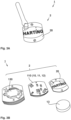
- Fig. 3A shows a plan view of a hardware and software-supported measuring device 1 with a housing 2 according to a further exemplary embodiment which does not correspond to the invention
- Fig. 3B shows the measuring device 1 of Fig. 3A broken down into its essential components.
- the electronics 10 of the measuring device 1 is provided on a first circuit board 110, which is equipped with electrical and electronic components of a control unit 11 and a sensor unit 12, which for the sake of simplicity are Fig. 3B are not shown on the first circuit board 110. Otherwise, the electronics 10 corresponds to the one described above with reference to Fig. 1A and 1B described measuring device 1.
- the housing 2 has an upper cover 20 with a recess for connecting an external antenna and with further recesses for the contact of selected sensors with the surroundings of the housing 2.
- a battery holder 130 for a battery 13 is provided as a means for supplying energy to the electronics 10.
- the first circuit board 110 is arranged in a sandwich-like manner between the lower housing part and the cover 20.
- the housing 2 of the measuring device consists of Fig. 3A and 3B made at least partly of a non-conductive material.
- the measuring device 1 of Fig. 3A and 3B is particularly suitable for monitoring the operating status of a machine.
- Fig.4 shows a schematic representation of the essential components of a system suitable for carrying out a process.
- the system of Fig.4 comprises, for example, three measuring devices 1 arranged on a device 3 to be monitored with a housing 2 which is arranged on the device 3.
- the measuring device 1 can, for example, be like the measuring device 1 of Fig. 1A and 1B and the devices 3 to be monitored can, for example, be connectors 3 to be monitored.
- the system of Fig.4 further comprises a first hardware and software-supported control and/or evaluation device 5, wherein the measuring devices 1 and the first control and/or evaluation device 5 are set up for wireless bidirectional signal and/or data exchange.
- the system of Fig.4 advantageously also has a second hardware and software-supported control and/or evaluation device 6, wherein the first control and/or evaluation device 5 and the second control and/or evaluation device 6 are set up for bidirectional signal and/or data exchange.
- a system 3 according to Fig.4 is particularly suitable for carrying out a procedure described above, in which in which the first control and/or evaluation device 5 is connected to the measuring devices 1 for wireless signal and/or data transmission, and the first control and/or evaluation device 5 is further connected to the second first control and/or evaluation device 6 in a cable-supported and/or wireless manner.
- the second control and/or evaluation device 6 can be a host computer and/or a server which is networked with the first control and/or evaluation device 5 via a local or global network for signal and/or data transmission. According to a modification of the design of the system of Fig.4 the second control and/or evaluation device 6 can be a mobile phone as described above.
Landscapes
- Engineering & Computer Science (AREA)
- Physics & Mathematics (AREA)
- General Physics & Mathematics (AREA)
- Computer Networks & Wireless Communication (AREA)
- Chemical & Material Sciences (AREA)
- Chemical Kinetics & Catalysis (AREA)
- Electrochemistry (AREA)
- General Chemical & Material Sciences (AREA)
- Microelectronics & Electronic Packaging (AREA)
- Manufacturing & Machinery (AREA)
- Arrangements For Transmission Of Measured Signals (AREA)
Description
- Die Erfindung betrifft eine Vorrichtung, aufweisend ein Gehäuse mit einer nicht verwendeten Kabeldurchführung und eine Hard- und Softwaregestützte Messeinrichtung zur Überwachung des Betriebszustands der Vorrichtung.
- Eine zu überwachende Vorrichtung kann beispielsweise eine Maschine und/oder ein Schaltschrank und/oder ein Steckverbinder und/oder eine größere Installationseinheit einer Vielzahl von beispielsweise Steckverbindern sein.
- Steckverbinder werden benötigt, um Verbindungen zur Signal- und/oder Energieübertragung auch zum Betrieb essentieller Einrichtungen, wie beispielsweise Versorgungseinrichtungen herzustellen. Verbindungen von beispielsweise elektrischen, pneumatischen oder optischen Signalen sind sensibel insbesondere auch gegenüber Umwelteinflüssen. Daher ist wünschenswert, den Betriebszustand der Verbindungen eines Steckverbinders und/oder eines Schaltschranks mit einer Vielzahl von Steckverbindern und auch von größeren Installationseinheiten mit einer Vielzahl von Steckverbindern insbesondere essentieller Einrichtungen zu überwachen.
- Aus der
DE 20 2007 018 306 U1 ist eine Messeinrichtung zur messtechnischen Erfassung einer Vielzahl physikalischer Messparameter für eine Steckverbindung eines modularen Steckverbinders bekannt. Die Messeinrichtung ist in einem ersten Modulgehäuse des Steckverbinders vorgesehen. Zur Signalübermittlung und Energieversorgung der Messeinrichtung ist eine Kontakteinheit in einem zweiten benachbarten Modulgehäuse vorgesehen, die die Signale mittels elektrischer Leiter an eine Kontrolleinrichtung weiterleitet. - Die bekannte Messeinrichtung beansprucht zwei Modulgehäuse eines Steckverbinders, wonach die mögliche Belegung bzw. Konfiguration des Steckverbinders und damit auch dessen Einsatzmöglichkeit nachteilhaft eingeschränkt ist. Dementsprechend sind auch die Einsatzmöglichkeiten der Messeinrichtung, auf Steckverbinder mit zwei freien benachbarten Modulplätzen beschränkt. Aus diesem Grund ist die bekannte Messeinrichtung auch nur nachteilhaft aufwendig und entsprechend kostspielig nachrüstbar. Dies ist insbesondere auch der Fall, nachdem die Messeinrichtung für Ihre Energieversorgung und Signalübermittlung verkabelt und entsprechend aufwendig zu installieren ist.
- Das Deutsche Patent- und Markenamt hat in der Prioritätsanmeldung zu vorliegender Anmeldung den folgenden Stand der Technik recherchiert:
DE 10 2011 075 807 A1 ,DE 20 2007 018 306 U1 undDE 20 2009 001 447 U1 . - Aus der
DE 20 2007 018 307 U1 ist eine Messeinrichtung für Steckverbinder bekannt, die in einem Steckerverbindergehäuse angeordnet ist, in dem ein oder mehrere elektrische Kontakte in dazu vorgesehenen Aufnahmeöffnungen eines Kontakteinsatzes angeordnet sind. Die Messeinrichtung ist dafür vorgesehen, einige physikalische Messparameter, die für eine Steckverbindung wie für eine größere Installationseinheit relevant sein können, messtechnisch zu erfassen. Hierfür ist einem oder mehreren elektrischen Kontakten im Kontakteinsatz mindestens ein Messsensor mit einer Auswerteeinheit der als Baugruppe ausgebildeten Messeinrichtung zugeordnet, wobei die als MID Trägerelement ausgebildete Baugruppe in einer Gehäusewand mit der Außenwand fluchtend eingesetzt ist. Die Anordnung erfolgt mittels einer Klebung oder dem Einschieben des Baugruppenträgers in eine entsprechende Vertiefung oder eines Verrastungsmechanismus auf der Innenseite des Steckverbindergehäuses. - Aus der
US 2010/0178806 A1 ist ein Koaxialkabelverbinder und ein Verfahren zum Ermitteln des Zustands einer Verbindung des Koaxialkabelverbinders mit einem HF-Port bekannt. Der Koaxialkabelverbinder umfasst einen Verbinderkörper und einen Statusmessschaltkreis für einen physikalischen Parameter, der innerhalb des Verbinderkörpers angeordnet ist. Der Statusmessschaltkreis für einen physikalischen Parameter ist vorgesehen, um einen Zustand des Verbinders zu messen, wenn dieser mit dem RF-Anschluss verbunden ist. Der Verbinderkörper weist außerdem eine Statusausgabekomponente auf, die elektrisch mit dem Messschaltkreis und einer Steuerlogikeinheit verbunden ist. Die Steuerlogikeinheit ist mit dem Messschaltkreis und der Statusausgabekomponente verbunden, und die Statusausgabekomponente steht in elektrischer Verbindung mit einem zentralen Leiter, um das Berichten des gemessenen Zustands des Verbinders zu ermöglichen. - Die Aufgabe der Erfindung besteht darin, eine einfach und kostengünstig zu installierende und nachrüstbare Messeinrichtung zur Überwachung des Betriebszustands einer Vorrichtung bereitzustellen, die insbesondere auch zur Überwachung auch von größeren Installationseinheiten geeignet ist.
- Dabei ist insbesondere Aufgabe der Erfindung eine Messeinrichtung zur Überwachung des Betriebszustands der Verbindungen eines Steckverbinders bereitzustellen.
- Die Aufgabe wird durch die Merkmale des unabhängigen Anspruchs gelöst.
- Vorteilhafte Ausgestaltungen der Erfindung sind in den abhängigen Ansprüche angegeben.
- Die vorliegende Erfindung betrifft eine Vorrichtung gemäß Anspruch 1, die insbesondere eine Maschine und/oder ein Schaltschrank und/oder ein Steckverbinder und/oder eine größere Installationseinheit einer Vielzahl von beispielsweise Steckverbindern sein kann.
- Die Vorrichtung weist ein Gehäuse mit einer nicht verwendeten Kabeldurchführung und eine Hard- und Softwaregestützte Messeinrichtung auf.
- Die Messeinrichtung weist wenigstens einen Sensor zur Erfassung von Messdaten wenigstens eines physikalischen Parameters auf, der den Betriebszustand der Vorrichtung charakterisiert.
- Die Messeinrichtung weist dabei besonders vorteilhaft eine autarke Elektronik mit einer Steuereinheit und mit einem Mittel zur Energieversorgung auf, das geeigneter Weise eine Batterie, ein Superkondensator oder eine Hybridbatterie sein kann. Auf diese Weise benötigt die Messeinrichtung insbesondere auch für ihre Energieversorgung keine zusätzlichen Leitungen.
- Die Messeinrichtung weist außerdem vorteilhaft eine Steuereinheit mit einem Mikrocontroller auf, der eine Funkschnittstelle zur Daten- und/oder Signalübertragung zu einer ersten Steuer- und/oder Auswerteeinrichtung bereitstellt, wonach die Messeinrichtung auch für ihre Daten- und/oder Signalübertragung keine zusätzlichen Leitungen benötigt.
- Die Messeinrichtung ist daher einfach zu installieren und auf einfache Weise und kostengünstig ohne einen entsprechenden Installationsaufwand auch in bereits im Betrieb befindliche Vorrichtungen und/oder Installationseinrichtungen nachrüstbar.
- Die Messeinrichtung weist hierfür geeigneter Weise ein für die nicht verwendete Kabeldurchführung durch das Gehäuse der Vorrichtung vorgesehenes und entsprechend als deren Blindstopfen ausgebildetes Gehäuse mit geeigneten Mitteln zur Befestigung der Messeinrichtung an der Vorrichtung auf.
- Der Blindstopfen ist im Wesentlichen als Hohlzylinder ausgebildet ist, und weist ein Außengewinde aus, das dazu geeignet ist, mit einem Innengewinde der Kabeldurchführung der Vorrichtung derart zu korrespondieren und geschraubt zu werden, dass mittels dem Blindstopfen das Gehäuse der Vorrichtung dicht verschließbar ist.
- Das Gehäuse der Messeinrichtung ist entsprechend mittels einem für die Vorrichtung vorgesehenen Blindstopfen bereitgestellt, in dem die Messeinrichtung zumindest teilweise beherbergt ist. Eine in einem Blindstopfen angeordnete Messeinrichtung ist besonders einfach und kostengünstig auch nachrüstbar zu installieren. Auch in bestehenden Installationen können bereits vorhandene Blindstopfen auf einfache Weise auch ohne Eingriffe in den Betrieb einer Vorrichtung, die eine Maschine sein kann und die besonders vorteilhaft ein Steckverbinder sein kann, ausgetauscht werden. Der Blindstopfen kann dabei ein erstes Gehäuse sein, in der die Messeinrichtung beherbergt ist. Der Blindstopfen kann auch ein zweites Gehäuse einer in einem ersten Gehäuse beherbergten Messeinrichtung sein, wobei das erste Gehäuse in dem Blindstopfen zumindest teilweise angeordnet ist.
- Besonders vorteilhaft ist ein für die Messeinrichtung geeigneter Blindstopfen ein für eine nicht verwendete Kabeldurchführung durch ein Maschinengehäuse oder ein Steckverbindergehäuse vorgesehener Blindstopfen. Ein derartiger geeigneter Blindstopfen wird nachfolgend auch unter Bezugnahme auf die Zeichnungen detailliert beschrieben. Die vorstehend genannte Funkschnittstelle kann geeigneter Weise ein Kommunikationsprotokoll mit einem Energieverbrauch von weniger als 1W und vorzugsweise von weniger als 0.5W und besonders bevorzugt von weniger als 0.1W und einen Spitzenstromverbrauch von weniger als 30mA und vorzugsweise weniger als 15mA aufweisen. Ein derartiges und für die vorstehende Messeinrichtung besonders bevorzugtes Kommunikationsprotokoll ist BLE (Blue Tooth Low Energy).
- Kommunikationsprotokolle mit einem vorstehenden Energieverbrauch und insbesondere BLE gestatten es, Daten effizient zu übermitteln und gleichzeitig Energiereserven zu schonen, indem sie lange Schlafenszeiten ermöglichen und energieintensive Bauteile wie die Funkschnittstelle möglichst selten ansprechen. Derartige Kommunikationsprotokolle und insbesondere BLE gestatten eine zuverlässige und robuste Signal- und/oder Datenübertragung zu einer Steuer- und/oder Auswerteeinrichtung über eine Entfernung von mindestens 10m und sind demnach auch für größere Installationseinheiten geeignet.
- Geeigneter Weise kann die Steuereinheit zur Daten- und/oder Signalübertragung eine Chip-Antenne aufweisen, wonach die Messeinrichtung besonders kompakt ausgebildet ist und lediglich einen geringen Raumbedarf hat. Eine vorstehende Messeinrichtung mit einer derartigen Steuereinheit kann in einer vorteilhaft kompakten Raumform bereitgestellt werden, die im Wesentlichen durch die Abmessungen des Mittels zur Energieversorgung der Messeinrichtung, das eine Batterie sein kann, und/oder eines für die Messeinrichtung vorgesehenen Blindstopfens und/oder eines im Inneren eines Gehäuses einer zu überwachenden Vorrichtung und insbesondere eines Steckverbindergehäuses und/oder einer Kabeldurchführung zur Verfügung stehenden Raums vorgegeben ist.
- Die Steuereinheit kann zur Daten- und/oder Signalübertragung weiterhin mit einer externen aus dem Gehäuse der Vorrichtung nach außen herausragenden Antenne verbunden sein, wodurch die Reichweite der Funkschnittstelle auch in unübersichtlichen größeren Installationen begünstigt wird.
- Geeigneter Weise kann die Steuereinheit mit einer Busschnittstelle ausgestattet sein, mittels der der Sensor an die Steuereinheit angebunden ist. Vorteilhaft kann dabei der Sensor auf einer Sensoreinheit angeordnet sein, wobei die Steuereinheit mit der Sensoreinheit bestückt sein kann, und die Sensoreinheit über die Busschnittstelle von der Steuereinheit angesprochen werden kann.
- Die Elektronik der Steuereinheit und die Elektronik der Sensoreinheit können für eine Messeinrichtung mit kompakter Raumform zusammen auf einer ersten Leiterplatte bereitgestellt sein, was auch für eine außen an einem Gehäuse einer zu überwachenden Vorrichtung vorgesehene und einfach zu installierende Messeinrichtung vorteilhaft ist.
- Die Elektronik der Steuereinheit kann weiterhin auf einer ersten Leiterplatte bereitgestellt sein und einen ersten Anschluss aufweisen, und die Elektronik der Sensoreinheit kann auf einer zweiten Leiterplatte bereitgestellt sein und einen zweiten Anschluss aufweisen, der mit dem ersten Anschluss derart korrespondiert, dass die Steuereinheit mit der Sensoreinheit bestückbar ist.
- Auf diese Weise kann vorteilhaft eine Vielzahl von unterschiedlichen Sensoreinheiten mit für vorbestimmte Anwendungen optimierten Sensoren und/oder Raumformen bereitgestellt werden. Dabei kann die Raumform der Sensoreinheit derart ausgebildet sein, dass der Sensor von der Steuereinheit beabstandet und vorteilhaft im Inneren des Gehäuses der zu überwachenden Vorrichtung auch in der Nachbarschaft einer interessierenden zu überwachenden Position angeordnet ist.
- Auf diese Weise kann der Sensor besonders vorteilhaft im Inneren des Gehäuses eines zu überwachenden Steckverbinders in der Nähe wenigstens einer mittels dem Steckverbinder bereitgestellten Verbindung angeordnet sein.
- Geeigneter Weise kann die Sensoreinheit mittels einem zwischen dem ersten und zweiten Anschluss vorgesehenen geeigneten Adapterkabel von der Steuereinheit beabstandet angeordnet sein. Auf diese Weise wird vorteilhaft die Möglichkeit geschaffen, den Sensor in unmittelbarer Nähe eines zu observierenden Bereichs, der insbesondere ein Kontaktbereich einer Steckverbindung sein kann, zu positionieren, wonach eine besonders sensible Überwachung von vorbestimmten zu überwachenden physikalischen Parametern ermöglicht ist.
- Eine derartige zu observierende Steckverbindung kann insbesondere eine elektrische Steckverbindung sein. Beispielsweise kann mittels einem in der Nachbarschaft von in Verbindung gebrachten elektrischen Kontakten angeordneten Hall Sensor eine Strommessung besonders zuverlässig durchgeführt werden.
- Neben der vorstehenden Funkschnittstelle und Busschnittstelle kann die Steuereinheit geeigneter Weise außerdem eine Einrichtung zur Datenspeicherung und/oder -Auswertung aufweisen.
- Weiterhin können die Steuereinheit und die Sensoreinheit geeigneter Weise derart ausgebildet und eingerichtet sein, dass die Messeinrichtung eine durchschnittliche Leistungsaufnahme von weniger als 100µA und vorzugsweise von weniger als 50µA aufweist. Zur Energieversorgung einer derartigen Messeinrichtung kann vorteilhaft eine mittels einer Knopfzelle bereitgestellte Batterie mit einer Kapazität von mindestens 70 mAh und vorzugsweise mindestens 180 mAh und mit einer Nennspannung von 2,5V bis 4,5V verwendet werden.
- Eine vorstehende Batterie hat eine vorteilhaft kompakte Bauform eines flachen Zylinders und ermöglicht bei der vorstehenden geeigneten Leistungsaufnahme der Elektronik der Messeinrichtung eine wünschenswerte Laufzeit von bis zu drei Jahren.
- Die erste Leiterplatte der Steuereinheit kann dabei geeigneter Weise einen Batteriehalter zur Beherbergung der Batterie aufweisen und dabei für eine wünschenswert kompakte Raumform vorteilhaft kreisförmig mit einer Abmessung ausgebildet sein, die im Wesentlichen durch die Abmessung der Batterie vorgegeben ist. Der erste Anschluss der Steuereinheit kann dabei geeigneter Weise derart auf der ersten Leiterplatte vorgesehen sein, und eine auf einer zweiten Leiterplatte angeordnete Sensoreinheit kann dabei außerdem derart ausgebildet sein, dass die Sensoreinheit die Steuereinheit radial seitlich nicht überragt und der Sensor der Sensoreinheit wünschenswert axial von der Steuereinheit beabstandet ist.
- Eine vorstehende Messeinrichtung kann darüber hinaus geeigneter Weise wenigstens einen Aktor zur Anzeige eines vorbestimmten erfassten/detektierten Betriebszustands und/oder zur Durchführung einer Aktion auf einen vorbestimmten Betriebszustand aufweisen. Beispielsweise und vorteilhaft kann ein derartiger Aktor eine LED zur optischen Anzeige eines vorbestimmten Betriebszustands sein, wobei die Anzeige einen fehlerfreien und/oder fehlerhaften und/oder kritischen Betriebszustand der Vorrichtung und/oder der Messeinrichtung anzeigen kann. Ein als eine LED ausgebildeter Aktor kann dabei von außen sichtbar an einem Gehäuse einer zu überwachenden Vorrichtung und insbesondere an einem vorstehend beschriebenen Blindstopfen angeordnet sein.
- Ein kritischer Betriebszustand der Vorrichtung kann beispielsweise eine erhöhte Betriebstemperatur sein, und ein kritischer Betriebszustand der Messeinrichtung kann beispielsweise eine niedrige Kapazität des Mittels zur Energieversorgung wie beispielsweise eine niedrige Batterieladung sein.
- Auf diese Weise ist auf einfache Weise die Möglichkeit der Identifikation und/oder Ortung einer beispielsweise in einem kritischen Betriebszustand befindlichen und/oder zu wartenden Vorrichtung bereitgestellt.
- Ein vorstehender Aktor kann weiterhin beispielsweise ein akustischer oder mechanischer Aktor sein, wobei ein mechanischer Aktor auf geeignete Weise eingerichtet und ausgebildet sein kann, den Betrieb einer Verbindung eines Steckverbinders zu unterbrechen.
- Eine vorstehende Messeinrichtung kann einen für viele Anwendungen geeigneten Sensor aufweisen, der einen physikalischen Parameter erfasst, der geeignet ist, einen Betriebszustand einer zu überwachenden Vorrichtung und insbesondere der Verbindungen eines Steckverbinders charakterisierenden Zustand zu erfassen. Ein derartiger Sensor kann ein Sensor zur Erfassung der Stromstärke sein, die über Kontakte einer elektrischen Verbindung geführt wird, und/oder ein Sensor zur Erfassung der dabei herrschenden Temperatur sein und/oder ein Feuchtigkeitssensor und/oder ein Beschleunigungssensor und/oder ein Hall-Sensor und/oder ein Magnet Sensor und/oder ein Lichtsensor sein. Eine vorstehende Messeinrichtung kann dabei auch eine Vielzahl von derartigen vorstehenden Sensoren aufweisen.
- Ein für eine erfindungsgemäße Messeinrichtung geeignetes Gehäuse und insbesondere ein geeigneter Blindstopfen ist wenigstens teilweise aus einem elektrisch nichtleitenden Material bereitgestellt, so dass eine zuverlässige Signal- und/oder Datenübertragung mittels der Funkschnittstelle der Steuereinheit der Messeinrichtung sichergestellt ist Ein für eine vorstehende Messeinrichtung besonders geeigneter
- Blindstopfen ist mittels einem für eine Kabeldurchführung einer Kabelverschraubung durch das Gehäuse einer zu überwachenden Vorrichtung vorgesehenen Blindstopfen bereitgestellt und entsprechend ausgebildet. Ein besonders geeigneter Blindstopfen kann insbesondere mittels einem für eine Kabeldurchführung einer Kabelverschraubung durch das Gehäuse eines Steckverbinders vorgesehenen Blindstopfen bereitgestellt sein und entsprechend ausgebildet sein. Derartige Blindstopfen können auf besonders einfache Weise auch in bereits Betrieb befindliche Installationen nachgerüstet werden.
- Ein weiteres nicht beanspruchtes Beispiel betrifft ein hard- und softwaregestütztes Verfahren zur Überwachung des Betriebszustands einer Vorrichtung, die eine Maschine und/oder ein Schaltschrank und/oder ein Steckverbinder und/oder eine größere Installationseinheit sein kann, unter Verwendung wenigstens einer Messeinrichtung mit wenigstens einem Sensor zur Erfassung von Messdaten wenigstens eines physikalischen Parameters, der den Betriebszustand der Vorrichtung charakterisiert. Die verwendete Messeinrichtung hat dabei eine elektronische Steuereinheit mit einem Mikrokontroller, der eine Funkschnittstelle aufweist.
- Bei dem vorstehenden Verfahren wird außerdem eine erste hard- und softwaregestützte Steuer- und/oder Auswerteeinrichtung verwendet, die mit der Messeinrichtung zur Signal- und/oder Datenübertragung drahtlos verbunden ist.
- Von der Messeinrichtung werden dabei Messdaten wenigstens eines physikalischen Parameters erfasst, der den Betriebszustand der Vorrichtung charakterisiert und wenigstens einer der nachfolgenden Schritte durchgeführt, die die Auswertung und/oder Sammlung und/oder Übertragung der von der Messeinrichtung erfassten Messdaten betreffen.
- Für ausgewählte Anwendungen kann wünschenswert sein, die von der Messeinrichtung erfassten Messdaten von der Messeinrichtung zumindest teilweise auszuwerten. Dies kann insbesondere für kleinere Installationseinheiten von nur wenigen zu überwachenden Vorrichtungen mit einer entsprechend geringen Anzahl von Messeinrichtungen von Vorteil sein.
- Beispielsweise kann bei der Überwachung lediglich einer Vorrichtung mittels auch vollständiger Auswertung der erfassten Messdaten bereits von der Messeinrichtung der Energieverbrauch der Messeinrichtung vorteilhaft minimiert werden, insbesondere auch nachdem hierbei eine Datenübertragung zu der ersten Steuer- und/oder Auswerteeinrichtung in entsprechend geringem Umfang durchgeführt werden kann. Der vorstehende vorteilhafte geringe Umfang der Durchführung der Datenübertragung kann deren Taktung und/oder den Umfang der übertragenen Daten und/oder Signale betreffen.
- Bei vollständiger Auswertung der erfassten Messdaten seitens der Messeinrichtung kann auch lediglich ein die Auswertung kennzeichnendes Signal an die erste Steuer- und/oder Auswerteeinrichtung übertragen werden.
- Für weitere ausgewählte Anwendungen kann wünschenswert sein, die von der Messeinrichtung erfassten Messdaten zu der ersten Steuer- und/oder Auswerteeinrichtung insbesondere auch gesammelt zu übertragen, wobei darüber hinaus geeigneter Weise die erste Steuer- und/oder Auswerteeinrichtung die von der Messeinrichtung erfassten Messdaten vorbestimmt zyklisch abfragen kann. Dies kann insbesondere für größere Installationseinheiten mit einer Vielzahl von überwachten Vorrichtungen mit einer entsprechend hohen Anzahl von Messeinrichtungen und/oder für kleinere sehr sensible Installationseinheiten von Vorteil sein.
- Geeigneter Weise können dabei die von der Messeinrichtung erfassten Messdaten von der ersten Steuer- und/oder Auswerteeinrichtung auch gesammelt und/oder zumindest teilweise ausgewertet werden.
- Die Sammlung und/oder Auswertung der Messdaten an einer zentralen Stelle, nämlich der ersten Steuer- und/oder Auswerteeinrichtung, gestattet eine umfangreiche auch weitergehende beispielsweise auch statistische Auswertung der Messdaten.
- Darüber hinaus kann die erste Steuer- und/oder Auswerteeinrichtung wie nachfolgend beschrieben mit einer weiteren zweiten Steuer- und/oder Auswerteeinrichtung signal- und/oder datentechnisch vernetzt sein, so dass die ausgewerteten Messdaten und/oder ein Signal einer bereits durchgeführten Auswertung an eine vorbestimmte geeignete Einrichtung und/oder Position übertragen werden können und dort zur weiteren Auswertung zur Verfügung stehen. Hierdurch wird wie nachfolgend beschrieben die Möglichkeit einer vorteilhaften Wartung bereitgestellt, wobei als fehlerhaft erkannte Betriebszustände zeitnah erkannt und beispielsweise durch Austausch fehlerhafter Vorrichtungen behoben werden können.
- Die zweite Steuer- und/oder Auswerteeinrichtung kann dabei geeigneter Weise mit einer Vielzahl von ersten Steuer- und/oder Auswerteeinrichtungen signal- und/oder datentechnisch vernetzt sein.
- Die Messdaten können wie vorstehend gesagt von der Messeinrichtung und/oder der ersten Steuer- und/oder Auswerteeinrichtung dahingehend auswertet werden, dass ein beispielsweise fehlerhafter oder auch wünschenswerter Betriebszustand der überwachten Vorrichtung festgestellt wird.
- Dabei können die Messdaten dahingehend auswertet werden, dass ein dem Auswerteergebnis entsprechendes Signal von der Messeinrichtung an einen Aktor erfolgt, der an ihrer Steuereinheit und/oder einer zu überwachenden Vorrichtung vorgesehen sein kann, wobei bei Auswertung der Messdaten seitens der ersten Steuer- und/oder Auswerteeinrichtung ein entsprechendes Signal an die Messeinrichtung erfolgen kann. Ein geeigneter Aktor kann beispielsweise eine optische Anzeige sein, wonach beispielsweise eine LED ein dem Auswerteergebnis entsprechenden erkannten Betriebszustand einer zu überwachenden Vorrichtung anzeigen kann.
- Es ist klar, dass insbesondere bei größeren Installationseinheiten von der Messeinrichtung neben den Messdaten geeigneter Weise auch weitere Daten wie beispielsweise Identifikationsdaten der Messeinrichtung und/oder einer zu überwachenden Vorrichtung an die erste Steuer- und/oder Auswerteeinrichtung übertragen werden und/oder abgefragt werden können. Die Identifikationsdaten können auch zur gezielten Kommunikation der ersten Steuer- und/oder Auswerteeinrichtung mit einer ausgewählten Messeinrichtung dienen. Bei Messeinrichtungen mit einer autarken beispielsweise und vorteilhaft mittels einer Batterie mit Energie versorgten Elektronik können die vorstehenden zu der ersten Steuer- und/oder Auswerteeinrichtung übertragenen Daten und/oder Signale geeigneter Weise auch Daten über den Batteriezustand der Messeinrichtung beinhalten.
- Bei dem Verfahren kann die Erfassung und/oder Sammlung und/oder Auswertung und/oder Abfragung und/oder Übertragung der Messdaten und/oder Signale von der Steuereinheit der Messeinrichtung und/oder der ersten Steuer- und/oder Auswerteeinrichtung geeigneter Weise derart durchgeführt werden, dass die Messeinrichtung eine durchschnittliche Leistungsaufnahme von weniger als 100µA und vorzugsweise von weniger als 50µA aufweist. Der vorstehende Betrieb der Messeinrichtung ist besonders energieeffizient und insbesondere für Messeinrichtungen mit einer autarken mittels einer Batterie mit Energie versorgten Elektronik von Vorteil, wonach eine derartige Messeinrichtung eine wünschenswert lange Lebensdauer hat.
- Je nach Anwendung kann hierbei die vorstehende Erfassung und/oder Sammlung und/oder Auswertung und/oder Abfragung und/oder Übertragung der Messdaten und/oder Signale jeweils vorbestimmt ausgewählt getaktet auf die jeweilige Anwendung optimiert durchgeführt werden. Beispielsweise kann bei Messeinrichtungen mit einem aktiven Sensor in einer Installationseinheit von höherer Sensibilität und/oder Priorität dessen Aktivierung zur Durchführung einer Messung entsprechend höhergetaktet vorteilhaft sein.
- Wie vorstehend erwähnt kann bei dem Verfahren darüber hinaus geeigneter Weise wenigstens eine zweite hard- und softwaregestützte Steuer- und/oder Auswerteeinrichtung verwendet werden, die mit der ersten Steuer- und/oder Auswerteeinrichtung zur Signal- und/oder Datenübertragung kabelgestützt und/oder drahtlos verbunden ist.
- Die von der ersten Steuer- und/oder Auswerteeinrichtung gesammelten und/oder ausgewerteten Daten und/oder ein den ausgewerteten Daten entsprechendes Signal können dabei zu der zweiten Steuer- und/oder Auswerteeinrichtung übertragen werden und/oder von der zweiten Steuer- und/oder Auswerteeinrichtung abgefragt werden, wobei die Daten und/oder das Signal von der zweiten Steuer- und/oder Auswerteeinrichtung geeigneter Weise gesammelt und/oder ausgewertet werden.
- Die Verwendung einer zweiten Steuer- und/oder Auswerteeinrichtung ist insbesondere von Vorteil bei Verwendung einer eingangs beschriebenen erfindungsgemäßen Messeinrichtung mit einer Funkschnittstelle und einem Kommunikationsprotokoll mit einem geringen Energieverbrauch und entsprechend begrenzter Reichweite.
- Die zweite Steuer- und/oder Auswerteeinrichtung kann dabei geeigneter Weise insbesondere ein Host- Computer und/oder ein Server sein, der mit der ersten Steuer- und/oder Auswerteeinrichtung über ein lokales oder globales Netzwerk zur Signal- und/oder Datenübertragung kabelgestützt und/oder drahtlos vernetzt ist.
- Die zweite Steuer- und/oder Auswerteeinrichtung kann darüber hinaus ein Mobiltelefon insbesondere eines Servicetechnikers sein.
- Die Messdaten und/oder das Signal können dabei von der zweiten Steuer- und/oder Auswerteeinrichtung geeigneter Weise neben weiteren beispielsweise auch statistischen Auswertungen und/oder Aktualisierungen von Protokollen auch dahingehend auswertet werden, dass ein dem Auswerteergebnis entsprechendes Signal an die erste Steuer- und/oder Auswerteeinrichtung und/oder ein Mobiltelefon eines Servicetechnikers erfolgt. Auf diese Weise ist wie vorstehend erwähnt eine wünschenswert zeitnahe Wartung einer insbesondere in einem kritischen Betriebszustand befindlichen zu überwachenden Vorrichtung ermöglicht.
- Die erste Steuer- und/oder Auswerteeinrichtung kann daraufhin das von der zweiten Steuer- und/oder Auswerteeinrichtung empfangene Signal dahingehend auswerten, dass ein dem Auswerteergebnis entsprechendes Signal an die Messeinrichtung erfolgt und/oder eine dem Auswerteergebnis entsprechende Taktung eines Abfragezyklus der Messeinrichtung eingerichtet wird.
- Das vorstehend beschriebene Verfahren, kann auf diese Weise optimiert angepasst auf unterschiedliche Installationseinheiten unter Berücksichtigung insbesondere auch deren Energieverbrauchs angewendet werden. Wie vorstehend gesagt ermöglicht das Verfahren auch deren wünschenswert zeitnahe Wartung.
- Ein weiteres nicht beanspruchtes Beispiel betrifft außerdem insbesondere ein zur Durchführung eines vorstehend beschriebenen erfindungsgemäßen Verfahrens geeignetes System zur Überwachung des Betriebszustands einer zu überwachenden Vorrichtung und insbesondere zur Überwachung des Betriebszustands der Verbindungen wenigstens eines Steckverbinders.
- Ein vorstehendes System umfasst wenigstens eine Messeinrichtung mit wenigstens einem Sensor zur Erfassung von Messdaten wenigstens eines physikalischen Parameters, der den Betriebszustand der zu überwachenden Vorrichtung und insbesondere wenigstens einer mittels einem Steckverbinder bereitgestellten Verbindung charakterisiert. Die Messeinrichtung hat dabei eine Steuereinheit mit einem Mikrokontroller, der eine Funkschnittstelle aufweist.
- Ein vorstehendes System weist dabei außerdem wenigstens eine erste hard- und softwaregestützte Steuer- und/oder Auswerteeinrichtung auf, wobei die Messeinrichtung und die erste Steuer- und/oder Auswerteeinrichtung zum drahtlosen bidirektionalen Signal- und/oder Datenaustausch eingerichtet sind.
- Die vorstehend beschriebenen Vorteile eines Verfahrens, wie beispielsweise dessen vielfältige Einsatzmöglichkeiten für Installationseinheiten vieler Anwendungen und die Ermöglichung einer zeitnahen Wartung gelten in gleicher Weise für ein erfindungsgemäßes System.
- Ein vorstehendes System kann geeigneter Weise insbesondere wenigstens eine eingangs beschriebene Messeinrichtung mit einer autarken Elektronik und einem Mittel zur Energieversorgung aufweisen, das eine Batterie, ein Superkondensator oder eine Hybridbatterie sein kann, und ist wie vorstehend beschrieben vorteilhaft einfach und kostengünstig zu installieren. Bezüglich der sich hieraus ergebenden weiteren Vorteile wird hier auf die vorstehende Beschreibung der erfindungsgemäßen Messeinrichtung verwiesen.
- Ein vorstehendes System kann darüber hinaus besonders vorteilhaft wenigstens eine zweite hard- und softwaregestützte Steuer- und/oder Auswerteeinrichtung aufweisen, wobei die erste Steuer- und/oder Auswerteeinrichtung und die zweite Steuer- und/oder Auswerteeinrichtung zum bidirektionalen Signal- und/oder Datenaustausch eingerichtet sind.
- Wie vorstehend zu dem Verfahren gesagt kann die zweite Steuer- und/oder Auswerteeinrichtung geeigneter Weise insbesondere ein Host- Computer und/oder ein Server und/oder ein Mobiltelefon sein, die mit der ersten Steuer- und/oder Auswerteeinrichtung über ein lokales oder globales Netzwerk zur Signal- und/oder Datenübertragung kabelgestützt und/oder drahtlos vernetzt sind.
- Ausführungsbeispiele der Erfindung sind in den Zeichnungen dargestellt und werden im Folgenden näher erläutert. Es zeigen:
- Fig. 1A
- eine Messeinrichtung nach einer Ausführung der Erfindung;
- Fig. 1B
- die Messeinrichtung von
Fig. 1A in ihre wesentlichen Bestandteile zerlegt; - Fig. 1C
- die Innenseite eines Blindstopfens nach einer Ausführung der Erfindung;
- Fig. 1D
- die Messeinrichtung von
Fig. 1A in dem Blindstopfen vonFig. 1C ; - Fig. 2A
- einen mit einem Blindstopfen von
Fig. 1D versehenen Steckverbinder; - Fig. 2B
- einen Teil eines Gehäuses eines weiteren mit einem Blindstopfen von
Fig. 1D versehenen Steckverbinders; - Fig. 2C
- das Gehäuse von
Fig. 2B von Innen; - Fig. 3A
- eine Messeinrichtung nach einer weiteren nicht erfindungsgemäßen Ausführung;
- Fig. 3B
- die Messeinrichtung von
Fig. 3A in ihre wesentlichen Bestandteile zerlegt; und - Fig. 4
- eine schematische Darstellung der wesentlichen Komponenten eines zur Durchführung eines Verfahrens geeigneten Systems,
- Die Figuren enthalten teilweise vereinfachte, schematische Darstellungen. Zum Teil werden für gleiche, aber gegebenenfalls nicht identische Elemente identische Bezugszeichen verwendet. Verschiedene Ansichten gleicher Elemente könnten unterschiedlich skaliert sein.
-
Fig. 1A zeigt eine Messeinrichtung 1 nach einer besonders vorteilhaften Ausführung der Erfindung undFig. 1B die Messeinrichtung 1 vonFig. 1A in ihre wesentlichen Bestandteile zerlegt. Die Messeinrichtung 1 vonFig. 1A und 1B ist besonders geeignet zur Überwachung einer Vorrichtung 3, die derart ausgebildet ist, dass sie eine zumindest teilweise Anordnung der Messeinrichtung 1 im Inneren ihres Gehäuses 30 gestattet, wobei die Vorrichtung 3 insbesondere ein Steckverbinder 3 sein kann. - Die Messeinrichtung 1 weist eine autarke Elektronik 10 mit einer Steuereinheit 11 und mit einer Batterie 13 als Mittel zur Energieversorgung auf. Die Batterie 13 ist geeigneter Weise eine Knopfzelle mit einer Kapazität von mindestens 70 mAh und vorzugsweise mindestens 180 mAh und mit einer Nennspannung von 2,5V bis 4,5V, die vorteilhaft flach zylindrisch ausgebildet ist.
- Die Batterie 13 ist in einem Batteriehalter auf einer ersten Leiterplatte 110 der Steuereinheit 11 vorgesehen, wobei die Raumform der ersten Leiterplatte 110 entsprechend den Abmessungen der Batterie 13 geeigneter Weise kreisförmig ausgebildet ist. Die Steuereinheit ist dementsprechend vorteilhaft kompakt ausgebildet.
- Die Elektronik 10 der Steuereinheit 11 weist neben dem Batteriehalter einen auf der Leiterplatte 110 angeordneten Mikrokontroller auf, der eine geeignete Funkschnittstelle zur Daten- und/oder Signalübertragung zu einer in der Zeichnung nicht dargestellten ersten Steuer- und/oder Auswerteeinrichtung bereitstellt.
- Die Elektronik 10 der Steuereinheit 11 weist weiterhin eine Busschnittstelle und einen auf der ersten Leiterplatte 110 ausgebildeten ersten Anschluss 111 auf, der mit einem zweiten Anschluss 121 einer zweiten Leiterplatte 120 einer Sensoreinheit 12 derart korrespondiert, dass die Leiterplatte 110 der Steuereinheit 11 mit der Sensoreinheit 12 bestückbar ist.
- Die zweite Leiterplatte 120 der Sensoreinheit 12 weist den mit dem Anschluss 111 der ersten Leiterplatte 110 korrespondierenden zweiten Anschluss 121 und wenigstens einen Sensor auf, der zur Erfassung eines physikalischen Parameters geeignet ist, der den Betriebszustand wenigstens einer Verbindung eines Steckverbinders 3 charakterisieren kann.
- Die über den ersten Anschluss 111 und den zweiten Anschluss 121 auf die Leiterplatte 110 der Steuereinheit 11 bestückte Sensoreinheit 12 erstreckt sich derart im Wesentlichen senkrecht von der Leiterplatte 110, dass der auf der Sensoreinheit 12 angeordnete Sensor von der Steuereinheit 11 beabstandet ist.
- Die Sensoreinheit 12 ist dabei derart ausgebildet und angeordnet, dass sie nicht radial seitlich über den umlaufenden Rand der kreisförmigen Leiterplatte 110 hinausragt. Die Messeinrichtung 1 mit der Sensoreinheit 12 und der Steuereinheit 11 ist auf diese Weise radial besonders kompakt ausgebildet und insbesondere zur zumindest teilweisen Beherbergung in einem nachfolgend unter Bezugnahme auf
Fig. 1C und 1D beschriebenen Blindstopfen 2 geeignet. Der Blindstopfen 2 bildet dabei ein Gehäuse 2 der Messeinrichtung 1. Der auf der Sensoreinheit 12 befindliche Sensor ist dabei außerdem wünschenswert axial von der Steuereinheit 11 beabstandet. -
Fig. 1C zeigt die Innenseite eines vorstehend erwähnten Blindstopfens 2 nach einer Ausführung der Erfindung, der insbesondere für eine Kabeldurchführung 31 durch ein Gehäuse 30 eines Steckverbinders 3 geeignet ist. Beispiele eines Steckverbinders 3 mit einer derartigen Kabeldurchführung 31 werden nachfolgend unter Bezugnahme aufFig. 3A, 3B und 3C beschrieben. - Der Blindstopfen 2 ist erfindungsgemäß im Wesentlichen als Hohlzylinder ausgebildet, der ein Außengewinde aufweist, das mit einem Innengewinde einer Kabeldurchführung 31 derart korrespondiert, dass der Blindstopfen 2 geeignet ist, derart in eine Kabeldurchführung 31 geschraubt zu werden, dass mittels dem Blindstopfen 2 ein Gehäuse 30 eines Steckverbinders 3 dicht verschlossen ist.
- Der zylindrische Blindstopfen 2 hat auf der einen Seite seines Zylinders einen Kopf, der radial seitlich geringfügig über den Zylinder hinausragt, so dass der Kopf bei einem mit einer Kabeldurchführung 31 verschraubten Blindstopfen 2 außenseitig benachbart zu dem Gehäuse 30 angeordnet ist.
- Der Blindstopfen 2 ist wenigstens teilweise aus einem elektrisch nichtleitenden Material bereitgestellt, so dass der Blindstopfen 2 geeignet ist, die Funktion der Funkschnittstelle der Steuereinheit 11 der Messeinrichtung 1 zu gewährleisten.
-
Fig. 1D zeigt die Messeinrichtung 1 vonFig. 1A in dem Blindstopfen 2 vonFig. 1C angeordnet, wobei die kreisförmige Leiterplatte 110 der Steuereinheit 11 in dem zylindrischen Blindstopfen 2 angeordnet ist und beispielsweise mit dem Blindstopfen 2 verklebt sein kann. - Die Sensoreinheit 12 ragt dabei vorteilhaft aus dem Hohlzylinder des Blindstopfens 2 heraus und ist in
Fig. 1D teilweise sichtbar, während die Steuereinheit 11 der Messeinrichtung in der Zeichnung insbesondere durch den Kopf des Blindstopfens 2 verdeckt ist. - Bei einem Sensor nach
Fig. 1A-D kann ein Sensoreinheit 12 sowohl innen (wie zu sehen) als auch außen sein. So ist es z.B. möglich, die Innentemperatur mit der Außentemperatur zu vergleichen. Das ist beispielsweise relevant für die Bewertung, ob eine Temperaturerhöhung im Steckverbinder durch zu hohe Ströme und/oder einem Defekt oder durch eine höhere Außentemperatur zustande kommt. Gleiches gilt auch Feuchtigkeits- oder Lichtsensoren. -
Fig. 2A zeigt einen mit einem Blindstopfen 2 vonFig. 1D versehenen Steckverbinder 3 mit einem Gehäuse 30 und einem Kabel 4, das durch eine Kabeldurchführung von oben in das Innere des Gehäuses 30 des Steckverbinders 3 geführt ist. Der Steckverbinder 3 ist dabei mit einem für ihn vorgesehenen Anschluss verbunden. Der Steckverbinder 3 ist dabei eine von der Messeinrichtung 1 zu überwachende Vorrichtung 3. - Das Gehäuse 30 des Steckverbinders bzw. der zu überwachenden Vorrichtung 3 von
Fig. 2A weist seitlich eine weitere nicht genutzte Kabeldurchführung 31 auf, die von einem mit einer Messeinrichtung 1 versehenen Blindstopfen 2 vonFig. 1D verschlossen ist. Dabei ragt die Sensoreinheit 12 wie in Fig. 2D dargestellt axial aus dem zylindrischen Blindstopfen 2 heraus und erstreckt sich in das Innere des Gehäuses 30. Auf diese Weise ist ein Sensor der Sensoreinheit 12 vorteilhaft im Inneren des Gehäuses 30 des Steckverbinders 3 angeordnet. -
Fig. 2B zeigt einen Teil eines Gehäuses 30 eines weiteren mit einem Blindstopfen vonFig. 1D versehenen Steckverbinders 3, wobei in der Zeichnung der Einfachheit und Übersichtlichkeit lediglich ein hier interessierender oberer Teil des Gehäuses 30 mit zwei Kabeldurchführungen 31 dargestellt ist. Dabei ist eine der beiden Kabeldurchführungen 31 mit einem Blindstopfen 2 versehen, während die andere Kabeldurchführung 31 offen ist. -
Fig. 2C zeigt das Gehäuse 30 vonFig. 2B von Innen. Die Messeinrichtung 1 mit der Steuereinheit 11, der Batterie 13 und der sich aus dem Blindstopfen 2 heraus und in das Innere das Gehäuses 30 erstreckenden Sensoreinheit 12 ist in dem Blindstopfen 2 angeordnet. - Für eine wünschenswerte weitere Beabstandung des Sensors der Sensoreinheit 12 von der Steuereinheit 11 und dem Blindstopfen 2 kann ein in den Zeichnungen nicht dargestelltes Adapterkabel die Anschlüsse 111 und 121 verbinden. Auf diese Weise kann ein auf der Sensoreinheit 12 angeordneter Sensor an einer vorbestimmten Position von besonderem Interesse insbesondere auch in der Nachbarschaft einer mittels einem Steckverbinder 3 bereitgestellten insbesondere elektrischen Verbindung im Inneren des Gehäuses 30 des Steckverbinders 3 angeordnet werden.
-
Fig. 3A zeigt eine Draufsicht auf eine hard- und softwaregestützte Messeinrichtung 1 mit einem Gehäuse 2 nach einer weiteren beispielhaften Ausführung, die der Erfindung nicht entspricht, undFig. 3B zeigt die Messeinrichtung 1 vonFig. 3A in ihre wesentlichen Bestandteile zerlegt. - Die Elektronik 10 der Messeinrichtung 1 ist auf einer ersten Leiterplatte 110 vorgesehen, die mit elektrischen und elektronischen Bauelementen einer Steuereinheit 11 und einer Sensoreinheit 12 bestückt ist, die der Einfachheit halber in
Fig. 3B nicht auf der ersten Leiterplatte 110 dargestellt sind. Ansonsten entspricht die Elektronik 10 der vorstehend unter Bezugnahme aufFig. 1A und 1B beschriebenen Messeinrichtung 1. - Das Gehäuse 2 hat eine obere Abdeckung 2 mit einer Ausnehmung für einen Anschluss einer externen Antenne und mit weiteren Ausnehmungen für den Kontakt von ausgewählten Sensoren mit der Umgebung des Gehäuses 2. In einem unteren Gehäuseteil ist ein Batteriehalter 130 für eine Batterie 13 als Mittel zur Energieversorgung der Elektronik 10 vorgesehen. Die erste Leiterplatte 110 ist dabei sandwichartig zwischen dem unteren Gehäuseteil und der Abdeckung 20 angeordnet.
- Wie der vorstehend beschriebene Blindstopfen 2 besteht das Gehäuse 2 der Messeinrichtung von
Fig. 3A und 3B aus zumindest teilweise aus einem nichtleitenden Material. - An dem seitlichen Rand des Gehäuses 2 sind zwei gegenüberliegende durchgehende Bohrungen zur Befestigung der Messeinrichtung 1 an ihrer bestimmungsgemäßen Position an einer zu überwachenden Vorrichtung mittels Schrauben vorgesehen. Die Messeinrichtung 1 von
Fig. 3A und 3B ist besonders geeignet zur Überwachung des Betriebszustands einer Maschine. -
Fig. 4 zeigt eine schematische Darstellung der wesentlichen Komponenten eines zur Durchführung eines Verfahrens geeigneten Systems. - Das System von
Fig. 4 umfasst beispielhaft drei an einer zu überwachenden Vorrichtung 3 angeordneten Messeinrichtungen 1 mit einem Gehäuse 2, das an der Vorrichtung 3 angeordnet ist. Gegenüber den Darstellungen vonFig. 1A, 1D und2A sind die Messeinrichtung 1, das Gehäuse 2 und die Vorrichtung 3 inFig. 3 vergleichsweise stark schematisiert. Die Messeinrichtungen 1 können beispielsweise wie die Messeinrichtung 1 vonFig. 1A und 1B ausgebildet sein, und die zu überwachenden Vorrichtungen 3 können beispielsweise zu überwachende Steckverbinder 3 sein. - Das System von
Fig. 4 weist dabei außerdem eine erste hard- und softwaregestützte Steuer- und/oder Auswerteeinrichtung 5 auf, wobei die Messeinrichtungen 1 und die erste Steuer- und/oder Auswerteeinrichtung 5 zum drahtlosen bidirektionalen Signal- und/oder Datenaustausch eingerichtet sind. - Das System von
Fig. 4 weist dabei vorteilhaft außerdem eine zweite hard- und softwaregestützte Steuer- und/oder Auswerteeinrichtung 6 auf, wobei die erste Steuer- und/oder Auswerteeinrichtung 5 und die zweite Steuer- und/oder Auswerteeinrichtung 6 zum bidirektionalen Signal- und/oder Datenaustausch eingerichtet sind. - Ein System 3 gemäß
Fig. 4 ist zur Durchführung eines eingangs beschriebenen Verfahrens besonders geeignet, bei dem die erste Steuer- und/oder Auswerteeinrichtung 5 mit den Messeinrichtungen 1 zur drahtlosen Signal- und/oder Datenübermittlung miteinander verbunden sind, und die erste Steuer- und/oder Auswerteeinrichtung 5 darüber hinaus mit der zweiten erste Steuer- und/oder Auswerteeinrichtung 6 kabelgestützt und/oder drahtlos verbunden ist. - Die zweite Steuer- und/oder Auswerteeinrichtung 6 kann dabei geeigneter Weise insbesondere ein Host- Computer und/oder ein Server sein, der mit der ersten Steuer- und/oder Auswerteeinrichtung 5 über ein lokales oder globales Netzwerk zur Signal- und/oder Datenübertragung vernetzt ist. Nach einer Abwandlung der Ausführung des Systems von
Fig. 4 kann die zweite Steuer- und/oder Auswerteeinrichtung 6 wie vorstehend beschrieben ein Mobiltelefon sein. -
- 1
- Messeinrichtung
- 10
- Elektronik
- 11
- Steuereinheit
- 110
- erste Leiterplatte
- 111
- erster Anschluss
- 12
- Sensoreinheit
- 120
- zweite Leiterplatte
- 121
- zweiter Anschluss
- 13
- Mittel zur Energieversorgung, Batterie
- 130
- Batteriehalter
- 2
- Gehäuse, Blindstopfen
- 20
- Abdeckung
- 3
- Vorrichtung, Steckverbinder
- 30
- Gehäuse
- 31
- Kabeldurchführung
- 4
- Kabel
- 5
- erste Steuer- und/oder Auswerteeinrichtung
- 6
- zweite Steuer- und/oder Auswerteeinrichtung
Claims (8)
- Vorrichtung (3), aufweisend ein Gehäuse (30) mit einer nicht verwendeten Kabeldurchführung (31) und eine Hard- und Softwaregestützte Messeinrichtung (1) für die Vorrichtung (3),wobei die Messeinrichtung (1) wenigstens einen Sensor zur Erfassung von Messdaten wenigstens eines physikalischen Parameters aufweist, der den Betriebszustand der Vorrichtung (3) charakterisiert,wobei die Messeinrichtung (1) eine autarke Elektronik (10) mit einer Steuereinheit (11) und ein Mittel zur Energieversorgung (13) aufweist, undwobei die Steuereinheit (11) einen Mikrocontroller aufweist, der eine Funkschnittstelle zur Daten- und/oder Signalübertragung zu einer Steuer- und/oder Auswerteeinrichtung (5) aufweist,wobei die Messeinrichtung (1) ein für die nicht verwendete Kabeldurchführung (31) durch das Gehäuse (30) der Vorrichtung (3) vorgesehenes und entsprechend als deren Blindstopfen (2) ausgebildetes Gehäuse (2) aufweist, in dem die Messeinrichtung (1) zumindest teilweise angeordnet ist, wobei das Gehäuse (2) der Messeinrichtung (1) nachrüstbar an der Vorrichtung (3) befestigt istdadurch gekennzeichnet, dassder Blindstopfen (2) im Wesentlichen als Hohlzylinder ausgebildet ist, und ein Außengewinde ausweist, das dazu geeignet ist, mit einem Innengewinde der Kabeldurchführung (31) der Vorrichtung (3) derart zu korrespondieren und geschraubt zu werden, dass mittels dem Blindstopfen (2) das Gehäuse (30) der Vorrichtung (3) dicht verschließbar ist.
- Vorrichtung (3) nach Anspruch 1, wobei die Funkschnittstelle für das Kommunikationsprotokoll BLE (Blue Tooth Low Energy) eingerichtet ist und dabei einen Energieverbrauch von weniger als 1W und vorzugsweise von weniger als 0.5W und besonders bevorzugt von weniger als 0.1W aufweist und einen Spitzenstromverbrauch von weniger als 30mA und vorzugsweise weniger als 15mA aufweist, und wobei die Steuereinheit (11) eine Chip-Antenne aufweist oder mit einer externen aus dem Blindstopfen nach außen herausragenden Antenne verbunden ist
- Vorrichtung (3) nach einem der Ansprüche 1 oder 2, wobei die Steuereinheit (11) eine Busschnittstelle aufweist, und über die Busschnittstelle mit einer Sensoreinheit (12) bestückt ist, die den Sensor aufweist.
- Vorrichtung (3) nach Anspruch 3, wobeidie Elektronik (10) der Steuereinheit (11) auf einer ersten Leiterplatte (110) mit einem ersten Anschluss (111) bereitgestellt ist, unddie Elektronik (10) der Sensoreinheit (12) auf einer zweiten Leiterplatte (120) mit einem zweiten Anschluss (121) bereitgestellt ist, wobeider erste Anschluss (111) mit dem zweiten Anschluss (121) derart korrespondiert, dass die Steuereinheit (11) mit der Sensoreinheit (12) bestückbar ist.
- Vorrichtung (3) nach Anspruch 4, wobei die Sensoreinheit (12) mittels einem Adapterkabel von der Steuereinheit (11) beabstandet ist, und die erste Leiterplatte (110) kreisförmig ausgebildet ist, und die Sensoreinheit (12) nicht über den seitlichen Rand der ersten Leiterplatte (110) hinausragt.
- Vorrichtung (3) nach einem der Ansprüche 2 bis 5, wobei die Steuereinheit (11) einen Batteriehalter aufweist, und das Mittel zur Energieversorgung eine Batterie (13) mit einer Kapazität von mindestens 70 mAh und vorzugsweise mindestens 180 mAh und mit einer Nennspannung von 2,5V bis 4,5V ist, wobei die Steuereinheit (11) derart ausgebildet und eingerichtet ist, dass die Messeinrichtung (1) eine durchschnittliche Leistungsaufnahme von wenige als 100µA und vorzugswiese von weniger als 50µA aufweist.
- Vorrichtung (3) nach einem der Ansprüche 1 bis 6, mit einem Sensor zur Erfassung der Stromstärke, die über Kontakte einer elektrischen Verbindung geführt wird, und/oder einem Sensor zur Erfassung der dabei herrschenden Temperatur und/oder einem Feuchtigkeitssensor und/oder einem Beschleunigungssensor und/oder einem Hall-Sensor und/oder einem Magnet Sensor und/oder einem Lichtsensor, und wobei die Messeinrichtung (1) wenigstens einen Aktor aufweist, der eine LED sein kann.
- Vorrichtung (3) nach einem der Ansprüche 1 bis 7, wobeidie Vorrichtung (3) ein Steckverbinder (3) ist, unddas Gehäuse (2) wenigstens teilweise aus einem elektrisch nichtleitenden Material bereitgestellt ist.
Applications Claiming Priority (2)
| Application Number | Priority Date | Filing Date | Title |
|---|---|---|---|
| DE102018130509.5A DE102018130509A1 (de) | 2018-11-30 | 2018-11-30 | Messeinrichtung für Betriebszustand |
| PCT/DE2019/101007 WO2020108698A1 (de) | 2018-11-30 | 2019-11-25 | Messeinrichtung für betriebszustand |
Publications (2)
| Publication Number | Publication Date |
|---|---|
| EP3887767A1 EP3887767A1 (de) | 2021-10-06 |
| EP3887767B1 true EP3887767B1 (de) | 2024-08-21 |
Family
ID=68847914
Family Applications (1)
| Application Number | Title | Priority Date | Filing Date |
|---|---|---|---|
| EP19817952.5A Active EP3887767B1 (de) | 2018-11-30 | 2019-11-25 | Messeinrichtung für betriebszustand |
Country Status (5)
| Country | Link |
|---|---|
| US (1) | US11899046B2 (de) |
| EP (1) | EP3887767B1 (de) |
| CN (1) | CN113167608B (de) |
| DE (1) | DE102018130509A1 (de) |
| WO (1) | WO2020108698A1 (de) |
Families Citing this family (3)
| Publication number | Priority date | Publication date | Assignee | Title |
|---|---|---|---|---|
| DE102019135635A1 (de) * | 2019-12-20 | 2021-06-24 | Seepex Gmbh | Vorrichtung zur drahtlosen Übermittlung eines Signals |
| DE102020121752A1 (de) | 2020-08-19 | 2022-02-24 | Turck Holding Gmbh | Elektrischer Steckverbinder |
| US11879944B2 (en) * | 2022-03-21 | 2024-01-23 | Rosemount Inc. | Wireless process variable transmitter with removable power module |
Citations (2)
| Publication number | Priority date | Publication date | Assignee | Title |
|---|---|---|---|---|
| DE202007018305U1 (de) * | 2007-03-24 | 2008-06-12 | Harting Electric Gmbh & Co. Kg | Messeinrichtung an Steckkontakten |
| US20100194382A1 (en) * | 2007-09-24 | 2010-08-05 | John Mezzalingua Associates, Inc. | Method for determining electrical power signal levels in a transmission system |
Family Cites Families (37)
| Publication number | Priority date | Publication date | Assignee | Title |
|---|---|---|---|---|
| AT503172B8 (de) * | 2006-02-01 | 2008-07-15 | Moeller Produktions Und Vertri | Elektrische installationsanordnung, sowie verfahren zum betrieb einer elektrischen installationsanordnung |
| DE102006005633A1 (de) * | 2006-02-08 | 2007-08-23 | Knick Elektronische Messgeräte GmbH & Co. KG | Verbindungssystem, insbesondere Steckverbindungssystem zur Übertragung von Daten- und Energieversorgungssignalen |
| DE202007018306U1 (de) | 2007-03-24 | 2008-04-30 | Harting Electric Gmbh & Co. Kg | Messeinrichtung für modulare Steckverbinder |
| DE202007018307U1 (de) | 2007-03-24 | 2008-06-12 | Harting Electric Gmbh & Co. Kg | Messeinrichtung für Steckverbinder |
| US8400319B2 (en) * | 2007-09-24 | 2013-03-19 | John Mezzalingua Associates, Inc. | Coaxial cable connector with an external sensor and method of use thereof |
| US7733236B2 (en) | 2007-09-24 | 2010-06-08 | John Mezzalingua Associates, Inc. | Coaxial cable connector and method of use thereof |
| DE102008050393A1 (de) * | 2008-10-02 | 2010-04-08 | Sms Siemag Aktiengesellschaft | Anordnung und Verfahren zur Detektierung eines Betriebszustandes einer Strangführung |
| CN101403917B (zh) * | 2008-10-28 | 2010-08-18 | 华北电力大学 | 一种机网动态参数综合测量装置 |
| DE102009037201A1 (de) * | 2009-01-15 | 2010-07-22 | Bartec Gmbh | Elektrische Geräteeinheit |
| DE202009001447U1 (de) * | 2009-02-10 | 2009-06-25 | Süßmann, Stefan, Dipl.-Ing. (FH) | Mess-, Übertragungs- und Anzeigevorrichtung für Drücke von Nfz.-Druckluftbremsanlagen auf Basis der Bluetooth-Funktechnik in Verbindung mit PC, PDA, Mobiltelefon |
| GB2463332B (en) * | 2009-02-26 | 2011-05-25 | Advanced Fiber Products Ltd | Fibre optic connector assembly |
| US20120031984A1 (en) * | 2010-08-03 | 2012-02-09 | Massachusetts Institute Of Technology | Personalized Building Comfort Control |
| KR101500023B1 (ko) * | 2010-09-29 | 2015-03-06 | 현대자동차주식회사 | 셀 운전상태 모니터링용 가상 음원 발생 장치 및 방법 |
| JP6266348B2 (ja) * | 2011-02-16 | 2018-01-24 | セクアナ メディカル エージー | 体液管理システム |
| DE102011075807A1 (de) * | 2011-05-13 | 2012-11-15 | Amtec Advanced Measurement Messtechnischer Service Gmbh | Vorrichtung zum kontrollierten Verspannen von Flanschverbindungen |
| CH706927A1 (de) * | 2012-09-10 | 2014-03-14 | Selectron Systems Ag | Steckteil zur Bildung einer Steckverbindung. |
| DE202012013207U1 (de) * | 2012-10-01 | 2015-06-30 | Wika Alexander Wiegand Se & Co. Kg | Auswerteeinheit für eine physikalische Größe |
| DE202013002563U1 (de) * | 2013-03-13 | 2013-03-21 | Kries-Energietechnik Gmbh & Co.Kg | Spannungsprüfsystem für eine Hochspannungsanlage |
| DE102013105779A1 (de) * | 2013-06-05 | 2014-12-11 | Reichle & De-Massari Ag | Steckverbindervorrichtung |
| DE102013107964A1 (de) * | 2013-07-03 | 2015-01-08 | Endress + Hauser Conducta Gesellschaft für Mess- und Regeltechnik mbH + Co. KG | Messanordnung |
| DE102013227051B4 (de) * | 2013-12-20 | 2017-03-30 | Leoni Kabel Holding Gmbh | Messanordnung und Verfahren zur Temperaturmessung sowie Sensorkabel für eine derartige Messanordnung |
| US10431994B2 (en) | 2013-12-27 | 2019-10-01 | Schneider Electric USA, Inc. | Self-contained EVCS display |
| DE102014205361A1 (de) * | 2014-03-21 | 2015-09-24 | Robert Bosch Gmbh | Sensorvorrichtung und Verfahren zum Herstellen einer Sensorvorrichtung |
| US9583796B2 (en) * | 2014-04-01 | 2017-02-28 | Palo Alto Research Center Incorporated | Method for monitoring/managing electrochemical energy device by detecting intercalation stage changes |
| CN106489102A (zh) * | 2014-07-07 | 2017-03-08 | 西门子公司 | 信息物理系统中的电部件的运行 |
| CN104535105B (zh) * | 2014-11-27 | 2016-11-02 | 北京航天测控技术有限公司 | 一种设备状态监控信息终端 |
| DK3031659T3 (en) * | 2014-12-12 | 2019-02-25 | Energybus E V | Modular vehicle system with increased reliability |
| EP3056953A1 (de) * | 2015-02-11 | 2016-08-17 | Siemens Aktiengesellschaft | Autarkes Feldgerät der Automatisierungstechnik zur Fernüberwachung |
| CN104748992A (zh) * | 2015-03-13 | 2015-07-01 | 阿海珐有限公司 | 用于监测和评估旋转的机器的状态的装置和方法 |
| DE102015105212A1 (de) * | 2015-04-07 | 2016-10-13 | Turck Holding Gmbh | Schaltschranküberwachungsvorrichtung |
| CN107923942B (zh) * | 2015-05-08 | 2020-11-20 | 沃尔沃卡车集团 | 用于监测电池组中的多个电池单体的状态的方法 |
| US10230198B2 (en) * | 2016-09-29 | 2019-03-12 | Schneider Electric USA, Inc. | EVSE energy management system retrofit coupling |
| DE102016123970A1 (de) * | 2016-12-09 | 2018-06-14 | iq contec GmbH | Verbindungsvorrichtung, Überwachungsverfahren und Montagewerkzeug für eine Verbindungsvorrichtung |
| CN206596028U (zh) * | 2017-01-11 | 2017-10-27 | 昆明畴阳科技有限公司 | 服务器运行状态监控装置 |
| CN107230877A (zh) * | 2017-06-14 | 2017-10-03 | 厦门少坤智能科技有限公司 | 一种模块化智能排插 |
| CN107764332A (zh) * | 2017-10-30 | 2018-03-06 | 李毅 | 一种封闭母线运行检测系统 |
| DE202018103763U1 (de) * | 2018-07-02 | 2018-08-09 | Onyx Healthcare Inc. | Managementvorrichtung für ausziehbare mobile Batterien |
-
2018
- 2018-11-30 DE DE102018130509.5A patent/DE102018130509A1/de not_active Withdrawn
-
2019
- 2019-11-25 EP EP19817952.5A patent/EP3887767B1/de active Active
- 2019-11-25 US US17/279,526 patent/US11899046B2/en active Active
- 2019-11-25 WO PCT/DE2019/101007 patent/WO2020108698A1/de not_active Ceased
- 2019-11-25 CN CN201980078358.7A patent/CN113167608B/zh active Active
Patent Citations (2)
| Publication number | Priority date | Publication date | Assignee | Title |
|---|---|---|---|---|
| DE202007018305U1 (de) * | 2007-03-24 | 2008-06-12 | Harting Electric Gmbh & Co. Kg | Messeinrichtung an Steckkontakten |
| US20100194382A1 (en) * | 2007-09-24 | 2010-08-05 | John Mezzalingua Associates, Inc. | Method for determining electrical power signal levels in a transmission system |
Also Published As
| Publication number | Publication date |
|---|---|
| CN113167608A (zh) | 2021-07-23 |
| US20210341518A1 (en) | 2021-11-04 |
| EP3887767A1 (de) | 2021-10-06 |
| US11899046B2 (en) | 2024-02-13 |
| WO2020108698A1 (de) | 2020-06-04 |
| CN113167608B (zh) | 2024-02-13 |
| DE102018130509A1 (de) | 2020-06-04 |
Similar Documents
| Publication | Publication Date | Title |
|---|---|---|
| DE102013111714B4 (de) | Verfahren zur Funktionseinstellung einer Messstelle | |
| EP3887767B1 (de) | Messeinrichtung für betriebszustand | |
| DE202007018306U1 (de) | Messeinrichtung für modulare Steckverbinder | |
| EP3127192A2 (de) | Steckverbindersystem | |
| DE102018127939A1 (de) | Intelligenter Leistungsschalter | |
| EP3249415B1 (de) | Testpunktkarten-einrichtung für einen prüftisch mit fehlersuche | |
| DE202007018307U1 (de) | Messeinrichtung für Steckverbinder | |
| EP4200944B1 (de) | Elektrischer steckverbinder | |
| EP4089852B1 (de) | Modulare steckdose und verfahren zur automatischen parametrierung/einrichtung | |
| WO2012084394A1 (de) | Feldgerät mit einer batterieeinheit | |
| EP1360746A1 (de) | Steckvorrichtung mit integrierter diagnose-/auswerteschaltung, anzeige und schaltbaren abschlusswiderständen | |
| WO2021160756A1 (de) | Anordnung zur bewertung des zustandes und der qualität von niederspannungsnetzen | |
| DE102017125308B4 (de) | Schaltgerät mit Schnittstellenmodul | |
| DE202007018305U1 (de) | Messeinrichtung an Steckkontakten | |
| DE102014106816B4 (de) | Vorrichtung zur Ermittlung eines Ladestromes | |
| WO2022122334A1 (de) | Ladesteuerungsmodul, ladestation und ladesystem zur steuerung von ladevorgängen von traktionsenergiespeichern für elektrofahrzeuge | |
| DE102017102096A1 (de) | Verbinder mit erfassung des zusammensteckens unter eigener stromversorgung | |
| WO2024089200A1 (de) | Steckbares energiemessmodul | |
| WO2022189012A1 (de) | Messzelle für batteriemodule, batteriemodul und batterie | |
| DE102023116554A1 (de) | Energiemesseinheit zum Messen von elektrischen Energiemengen in Ladeanschlussvorrichtungen für Elektrofahrzeuge, sowie damit ausgestattete Ladeanschlussvorrichtung | |
| DE102012111018A1 (de) | Mehrkanaliges Messdatenerfassungsgerät | |
| EP4296696A1 (de) | Messmodul | |
| EP1772707B1 (de) | Messvorrichtung | |
| DE102021128111A1 (de) | Ladekabel und verfahren zum betreiben desselben | |
| LU507363B1 (de) | Vorrichtung und System zur Energiemessung |
Legal Events
| Date | Code | Title | Description |
|---|---|---|---|
| STAA | Information on the status of an ep patent application or granted ep patent |
Free format text: STATUS: UNKNOWN |
|
| STAA | Information on the status of an ep patent application or granted ep patent |
Free format text: STATUS: THE INTERNATIONAL PUBLICATION HAS BEEN MADE |
|
| PUAI | Public reference made under article 153(3) epc to a published international application that has entered the european phase |
Free format text: ORIGINAL CODE: 0009012 |
|
| STAA | Information on the status of an ep patent application or granted ep patent |
Free format text: STATUS: REQUEST FOR EXAMINATION WAS MADE |
|
| 17P | Request for examination filed |
Effective date: 20210628 |
|
| AK | Designated contracting states |
Kind code of ref document: A1 Designated state(s): AL AT BE BG CH CY CZ DE DK EE ES FI FR GB GR HR HU IE IS IT LI LT LU LV MC MK MT NL NO PL PT RO RS SE SI SK SM TR |
|
| DAV | Request for validation of the european patent (deleted) | ||
| DAX | Request for extension of the european patent (deleted) | ||
| STAA | Information on the status of an ep patent application or granted ep patent |
Free format text: STATUS: EXAMINATION IS IN PROGRESS |
|
| 17Q | First examination report despatched |
Effective date: 20221108 |
|
| P01 | Opt-out of the competence of the unified patent court (upc) registered |
Effective date: 20230603 |
|
| GRAP | Despatch of communication of intention to grant a patent |
Free format text: ORIGINAL CODE: EPIDOSNIGR1 |
|
| STAA | Information on the status of an ep patent application or granted ep patent |
Free format text: STATUS: GRANT OF PATENT IS INTENDED |
|
| RIC1 | Information provided on ipc code assigned before grant |
Ipc: G01L 19/08 20060101ALI20240426BHEP Ipc: H01R 13/66 20060101ALI20240426BHEP Ipc: H01R 13/629 20060101ALI20240426BHEP Ipc: H01M 50/216 20210101ALI20240426BHEP Ipc: G01D 21/02 20060101AFI20240426BHEP |
|
| INTG | Intention to grant announced |
Effective date: 20240513 |
|
| GRAS | Grant fee paid |
Free format text: ORIGINAL CODE: EPIDOSNIGR3 |
|
| GRAA | (expected) grant |
Free format text: ORIGINAL CODE: 0009210 |
|
| STAA | Information on the status of an ep patent application or granted ep patent |
Free format text: STATUS: THE PATENT HAS BEEN GRANTED |
|
| AK | Designated contracting states |
Kind code of ref document: B1 Designated state(s): AL AT BE BG CH CY CZ DE DK EE ES FI FR GB GR HR HU IE IS IT LI LT LU LV MC MK MT NL NO PL PT RO RS SE SI SK SM TR |
|
| RAP3 | Party data changed (applicant data changed or rights of an application transferred) |
Owner name: HARTING ELECTRIC STIFTUNG & CO. KG |
|
| REG | Reference to a national code |
Ref country code: GB Ref legal event code: FG4D Free format text: NOT ENGLISH |
|
| REG | Reference to a national code |
Ref country code: CH Ref legal event code: EP |
|
| REG | Reference to a national code |
Ref country code: IE Ref legal event code: FG4D Free format text: LANGUAGE OF EP DOCUMENT: GERMAN |
|
| REG | Reference to a national code |
Ref country code: DE Ref legal event code: R096 Ref document number: 502019011954 Country of ref document: DE |
|
| REG | Reference to a national code |
Ref country code: LT Ref legal event code: MG9D |
|
| REG | Reference to a national code |
Ref country code: NL Ref legal event code: MP Effective date: 20240821 |
|
| PG25 | Lapsed in a contracting state [announced via postgrant information from national office to epo] |
Ref country code: NO Free format text: LAPSE BECAUSE OF FAILURE TO SUBMIT A TRANSLATION OF THE DESCRIPTION OR TO PAY THE FEE WITHIN THE PRESCRIBED TIME-LIMIT Effective date: 20241121 |
|
| PG25 | Lapsed in a contracting state [announced via postgrant information from national office to epo] |
Ref country code: NL Free format text: LAPSE BECAUSE OF FAILURE TO SUBMIT A TRANSLATION OF THE DESCRIPTION OR TO PAY THE FEE WITHIN THE PRESCRIBED TIME-LIMIT Effective date: 20240821 Ref country code: GR Free format text: LAPSE BECAUSE OF FAILURE TO SUBMIT A TRANSLATION OF THE DESCRIPTION OR TO PAY THE FEE WITHIN THE PRESCRIBED TIME-LIMIT Effective date: 20241122 Ref country code: FI Free format text: LAPSE BECAUSE OF FAILURE TO SUBMIT A TRANSLATION OF THE DESCRIPTION OR TO PAY THE FEE WITHIN THE PRESCRIBED TIME-LIMIT Effective date: 20240821 Ref country code: PL Free format text: LAPSE BECAUSE OF FAILURE TO SUBMIT A TRANSLATION OF THE DESCRIPTION OR TO PAY THE FEE WITHIN THE PRESCRIBED TIME-LIMIT Effective date: 20240821 Ref country code: PT Free format text: LAPSE BECAUSE OF FAILURE TO SUBMIT A TRANSLATION OF THE DESCRIPTION OR TO PAY THE FEE WITHIN THE PRESCRIBED TIME-LIMIT Effective date: 20241223 |
|
| PG25 | Lapsed in a contracting state [announced via postgrant information from national office to epo] |
Ref country code: BG Free format text: LAPSE BECAUSE OF FAILURE TO SUBMIT A TRANSLATION OF THE DESCRIPTION OR TO PAY THE FEE WITHIN THE PRESCRIBED TIME-LIMIT Effective date: 20240821 |
|
| PG25 | Lapsed in a contracting state [announced via postgrant information from national office to epo] |
Ref country code: LV Free format text: LAPSE BECAUSE OF FAILURE TO SUBMIT A TRANSLATION OF THE DESCRIPTION OR TO PAY THE FEE WITHIN THE PRESCRIBED TIME-LIMIT Effective date: 20240821 |
|
| PG25 | Lapsed in a contracting state [announced via postgrant information from national office to epo] |
Ref country code: IS Free format text: LAPSE BECAUSE OF FAILURE TO SUBMIT A TRANSLATION OF THE DESCRIPTION OR TO PAY THE FEE WITHIN THE PRESCRIBED TIME-LIMIT Effective date: 20241221 |
|
| PG25 | Lapsed in a contracting state [announced via postgrant information from national office to epo] |
Ref country code: HR Free format text: LAPSE BECAUSE OF FAILURE TO SUBMIT A TRANSLATION OF THE DESCRIPTION OR TO PAY THE FEE WITHIN THE PRESCRIBED TIME-LIMIT Effective date: 20240821 |
|
| PG25 | Lapsed in a contracting state [announced via postgrant information from national office to epo] |
Ref country code: RS Free format text: LAPSE BECAUSE OF FAILURE TO SUBMIT A TRANSLATION OF THE DESCRIPTION OR TO PAY THE FEE WITHIN THE PRESCRIBED TIME-LIMIT Effective date: 20241121 Ref country code: ES Free format text: LAPSE BECAUSE OF FAILURE TO SUBMIT A TRANSLATION OF THE DESCRIPTION OR TO PAY THE FEE WITHIN THE PRESCRIBED TIME-LIMIT Effective date: 20240821 |
|
| PG25 | Lapsed in a contracting state [announced via postgrant information from national office to epo] |
Ref country code: RS Free format text: LAPSE BECAUSE OF FAILURE TO SUBMIT A TRANSLATION OF THE DESCRIPTION OR TO PAY THE FEE WITHIN THE PRESCRIBED TIME-LIMIT Effective date: 20241121 Ref country code: PT Free format text: LAPSE BECAUSE OF FAILURE TO SUBMIT A TRANSLATION OF THE DESCRIPTION OR TO PAY THE FEE WITHIN THE PRESCRIBED TIME-LIMIT Effective date: 20241223 Ref country code: PL Free format text: LAPSE BECAUSE OF FAILURE TO SUBMIT A TRANSLATION OF THE DESCRIPTION OR TO PAY THE FEE WITHIN THE PRESCRIBED TIME-LIMIT Effective date: 20240821 Ref country code: NO Free format text: LAPSE BECAUSE OF FAILURE TO SUBMIT A TRANSLATION OF THE DESCRIPTION OR TO PAY THE FEE WITHIN THE PRESCRIBED TIME-LIMIT Effective date: 20241121 Ref country code: NL Free format text: LAPSE BECAUSE OF FAILURE TO SUBMIT A TRANSLATION OF THE DESCRIPTION OR TO PAY THE FEE WITHIN THE PRESCRIBED TIME-LIMIT Effective date: 20240821 Ref country code: LV Free format text: LAPSE BECAUSE OF FAILURE TO SUBMIT A TRANSLATION OF THE DESCRIPTION OR TO PAY THE FEE WITHIN THE PRESCRIBED TIME-LIMIT Effective date: 20240821 Ref country code: IS Free format text: LAPSE BECAUSE OF FAILURE TO SUBMIT A TRANSLATION OF THE DESCRIPTION OR TO PAY THE FEE WITHIN THE PRESCRIBED TIME-LIMIT Effective date: 20241221 Ref country code: HR Free format text: LAPSE BECAUSE OF FAILURE TO SUBMIT A TRANSLATION OF THE DESCRIPTION OR TO PAY THE FEE WITHIN THE PRESCRIBED TIME-LIMIT Effective date: 20240821 Ref country code: GR Free format text: LAPSE BECAUSE OF FAILURE TO SUBMIT A TRANSLATION OF THE DESCRIPTION OR TO PAY THE FEE WITHIN THE PRESCRIBED TIME-LIMIT Effective date: 20241122 Ref country code: FI Free format text: LAPSE BECAUSE OF FAILURE TO SUBMIT A TRANSLATION OF THE DESCRIPTION OR TO PAY THE FEE WITHIN THE PRESCRIBED TIME-LIMIT Effective date: 20240821 Ref country code: ES Free format text: LAPSE BECAUSE OF FAILURE TO SUBMIT A TRANSLATION OF THE DESCRIPTION OR TO PAY THE FEE WITHIN THE PRESCRIBED TIME-LIMIT Effective date: 20240821 Ref country code: BG Free format text: LAPSE BECAUSE OF FAILURE TO SUBMIT A TRANSLATION OF THE DESCRIPTION OR TO PAY THE FEE WITHIN THE PRESCRIBED TIME-LIMIT Effective date: 20240821 |
|
| PG25 | Lapsed in a contracting state [announced via postgrant information from national office to epo] |
Ref country code: DK Free format text: LAPSE BECAUSE OF FAILURE TO SUBMIT A TRANSLATION OF THE DESCRIPTION OR TO PAY THE FEE WITHIN THE PRESCRIBED TIME-LIMIT Effective date: 20240821 Ref country code: RO Free format text: LAPSE BECAUSE OF FAILURE TO SUBMIT A TRANSLATION OF THE DESCRIPTION OR TO PAY THE FEE WITHIN THE PRESCRIBED TIME-LIMIT Effective date: 20240821 Ref country code: SM Free format text: LAPSE BECAUSE OF FAILURE TO SUBMIT A TRANSLATION OF THE DESCRIPTION OR TO PAY THE FEE WITHIN THE PRESCRIBED TIME-LIMIT Effective date: 20240821 |
|
| PG25 | Lapsed in a contracting state [announced via postgrant information from national office to epo] |
Ref country code: EE Free format text: LAPSE BECAUSE OF FAILURE TO SUBMIT A TRANSLATION OF THE DESCRIPTION OR TO PAY THE FEE WITHIN THE PRESCRIBED TIME-LIMIT Effective date: 20240821 |
|
| PG25 | Lapsed in a contracting state [announced via postgrant information from national office to epo] |
Ref country code: CZ Free format text: LAPSE BECAUSE OF FAILURE TO SUBMIT A TRANSLATION OF THE DESCRIPTION OR TO PAY THE FEE WITHIN THE PRESCRIBED TIME-LIMIT Effective date: 20240821 |
|
| PG25 | Lapsed in a contracting state [announced via postgrant information from national office to epo] |
Ref country code: IT Free format text: LAPSE BECAUSE OF FAILURE TO SUBMIT A TRANSLATION OF THE DESCRIPTION OR TO PAY THE FEE WITHIN THE PRESCRIBED TIME-LIMIT Effective date: 20240821 Ref country code: SK Free format text: LAPSE BECAUSE OF FAILURE TO SUBMIT A TRANSLATION OF THE DESCRIPTION OR TO PAY THE FEE WITHIN THE PRESCRIBED TIME-LIMIT Effective date: 20240821 |
|
| REG | Reference to a national code |
Ref country code: DE Ref legal event code: R097 Ref document number: 502019011954 Country of ref document: DE |
|
| PLBE | No opposition filed within time limit |
Free format text: ORIGINAL CODE: 0009261 |
|
| STAA | Information on the status of an ep patent application or granted ep patent |
Free format text: STATUS: NO OPPOSITION FILED WITHIN TIME LIMIT |
|
| REG | Reference to a national code |
Ref country code: CH Ref legal event code: PL |
|
| PG25 | Lapsed in a contracting state [announced via postgrant information from national office to epo] |
Ref country code: MC Free format text: LAPSE BECAUSE OF FAILURE TO SUBMIT A TRANSLATION OF THE DESCRIPTION OR TO PAY THE FEE WITHIN THE PRESCRIBED TIME-LIMIT Effective date: 20240821 |
|
| PG25 | Lapsed in a contracting state [announced via postgrant information from national office to epo] |
Ref country code: LU Free format text: LAPSE BECAUSE OF NON-PAYMENT OF DUE FEES Effective date: 20241125 |
|
| REG | Reference to a national code |
Ref country code: CH Ref legal event code: PL |
|
| PG25 | Lapsed in a contracting state [announced via postgrant information from national office to epo] |
Ref country code: CH Free format text: LAPSE BECAUSE OF NON-PAYMENT OF DUE FEES Effective date: 20241130 |
|
| 26N | No opposition filed |
Effective date: 20250522 |
|
| REG | Reference to a national code |
Ref country code: BE Ref legal event code: MM Effective date: 20241130 |
|
| PG25 | Lapsed in a contracting state [announced via postgrant information from national office to epo] |
Ref country code: SE Free format text: LAPSE BECAUSE OF FAILURE TO SUBMIT A TRANSLATION OF THE DESCRIPTION OR TO PAY THE FEE WITHIN THE PRESCRIBED TIME-LIMIT Effective date: 20240821 |
|
| PG25 | Lapsed in a contracting state [announced via postgrant information from national office to epo] |
Ref country code: BE Free format text: LAPSE BECAUSE OF NON-PAYMENT OF DUE FEES Effective date: 20241130 |
|
| PG25 | Lapsed in a contracting state [announced via postgrant information from national office to epo] |
Ref country code: IE Free format text: LAPSE BECAUSE OF NON-PAYMENT OF DUE FEES Effective date: 20241125 |
|
| PGFP | Annual fee paid to national office [announced via postgrant information from national office to epo] |
Ref country code: DE Payment date: 20251126 Year of fee payment: 7 |
|
| PGFP | Annual fee paid to national office [announced via postgrant information from national office to epo] |
Ref country code: GB Payment date: 20251125 Year of fee payment: 7 |
|
| PG25 | Lapsed in a contracting state [announced via postgrant information from national office to epo] |
Ref country code: AT Free format text: LAPSE BECAUSE OF NON-PAYMENT OF DUE FEES Effective date: 20241125 |
|
| PGFP | Annual fee paid to national office [announced via postgrant information from national office to epo] |
Ref country code: FR Payment date: 20251124 Year of fee payment: 7 |
|
| REG | Reference to a national code |
Ref country code: AT Ref legal event code: MM01 Ref document number: 1715894 Country of ref document: AT Kind code of ref document: T Effective date: 20241125 |
|
| PG25 | Lapsed in a contracting state [announced via postgrant information from national office to epo] |
Ref country code: HU Free format text: LAPSE BECAUSE OF FAILURE TO SUBMIT A TRANSLATION OF THE DESCRIPTION OR TO PAY THE FEE WITHIN THE PRESCRIBED TIME-LIMIT; INVALID AB INITIO Effective date: 20191125 |
|
| PG25 | Lapsed in a contracting state [announced via postgrant information from national office to epo] |
Ref country code: CY Free format text: LAPSE BECAUSE OF FAILURE TO SUBMIT A TRANSLATION OF THE DESCRIPTION OR TO PAY THE FEE WITHIN THE PRESCRIBED TIME-LIMIT; INVALID AB INITIO Effective date: 20191125 |