EP3888281B1 - Verfahren zur trennung von referenzsymbolen und benutzerdaten in einer unteren schichtteilung - Google Patents
Verfahren zur trennung von referenzsymbolen und benutzerdaten in einer unteren schichtteilung Download PDFInfo
- Publication number
- EP3888281B1 EP3888281B1 EP19802285.7A EP19802285A EP3888281B1 EP 3888281 B1 EP3888281 B1 EP 3888281B1 EP 19802285 A EP19802285 A EP 19802285A EP 3888281 B1 EP3888281 B1 EP 3888281B1
- Authority
- EP
- European Patent Office
- Prior art keywords
- data
- daci
- network
- message
- downlink
- Prior art date
- Legal status (The legal status is an assumption and is not a legal conclusion. Google has not performed a legal analysis and makes no representation as to the accuracy of the status listed.)
- Active
Links
Images








Classifications
-
- H—ELECTRICITY
- H04—ELECTRIC COMMUNICATION TECHNIQUE
- H04L—TRANSMISSION OF DIGITAL INFORMATION, e.g. TELEGRAPHIC COMMUNICATION
- H04L5/00—Arrangements affording multiple use of the transmission path
- H04L5/003—Arrangements for allocating sub-channels of the transmission path
- H04L5/0044—Allocation of payload; Allocation of data channels, e.g. PDSCH or PUSCH
-
- H—ELECTRICITY
- H04—ELECTRIC COMMUNICATION TECHNIQUE
- H04W—WIRELESS COMMUNICATION NETWORKS
- H04W72/00—Local resource management
- H04W72/50—Allocation or scheduling criteria for wireless resources
- H04W72/56—Allocation or scheduling criteria for wireless resources based on priority criteria
-
- H—ELECTRICITY
- H04—ELECTRIC COMMUNICATION TECHNIQUE
- H04L—TRANSMISSION OF DIGITAL INFORMATION, e.g. TELEGRAPHIC COMMUNICATION
- H04L5/00—Arrangements affording multiple use of the transmission path
- H04L5/0001—Arrangements for dividing the transmission path
- H04L5/0014—Three-dimensional division
- H04L5/0023—Time-frequency-space
-
- H—ELECTRICITY
- H04—ELECTRIC COMMUNICATION TECHNIQUE
- H04L—TRANSMISSION OF DIGITAL INFORMATION, e.g. TELEGRAPHIC COMMUNICATION
- H04L5/00—Arrangements affording multiple use of the transmission path
- H04L5/003—Arrangements for allocating sub-channels of the transmission path
- H04L5/0048—Allocation of pilot signals, i.e. of signals known to the receiver
-
- H—ELECTRICITY
- H04—ELECTRIC COMMUNICATION TECHNIQUE
- H04W—WIRELESS COMMUNICATION NETWORKS
- H04W72/00—Local resource management
- H04W72/04—Wireless resource allocation
- H04W72/044—Wireless resource allocation based on the type of the allocated resource
-
- H—ELECTRICITY
- H04—ELECTRIC COMMUNICATION TECHNIQUE
- H04W—WIRELESS COMMUNICATION NETWORKS
- H04W72/00—Local resource management
- H04W72/20—Control channels or signalling for resource management
Definitions
- the present disclosure relates generally to communications, and more particularly, to wireless communications and related wireless devices and network nodes.
- the document US 2018/0227028 A1 describes a method using a split Layer 1 architecture comprising a remote unit and a digital unit. A first portion of the physical layer is located in the remote unit, and a second portion of the physical layer is located in the digital unit. A frequency domain compression with statistical multiplexing is applied to a first portion of a signal, which is processed at the first portion of the physical layer. The compressed first portion of the signal and a second portion of the signal are transmitted to the second portion of the physical layer.
- a protocol may include data-associated control information (“DACI”) messages, which may be transmitted from the LLS-CU to a RU.
- the DACI messages may contain information about how to treat user data messages, transmitted LLS-CU to RU, with content to be transmitted over the air, or control data to be received over the air that is included in user data messages transmitted from RU to LLS-CU.
- the user data messages may be referred to as user data downlink (“UD-DL”) and user data uplink (“UD-UL”).
- the Section Type 1 DACI message may include a list of Sections including: an identifier to map the DACI and UD-DL or UD-UL: Section ID; a logical RU port to support multiple overlapping (in time/frequency) and independent address ranges of identifiers; a data direction: UL/DL; a range of physical resource blocks, PRBs; a range of reference symbols, RS; information regarding which resource elements, REs, in the PRB range the rest of the information relates to; optional beam forming index or weights; optional compression method for beam forming weights; or user data (“UD”) format and optional compression method.
- multiplexing reference symbols and user data may provide that the user data DACI sets the boundary conditions and for each user data DACI a corresponding reference symbol DACI may be sent. Separate reference symbol DACI may need to be sent for each gap in PRBs after the user data allocation is complete. For each user data UD-DL, the reference symbols may need to be multiplexed by the LLS-CU in the right sample position. For each gap in the user data allocation, the LLS-CU may need to generate a UD-DL with the samples for that symbol.
- Such approaches may lead to challenges that may include unnecessary signaling overhead since the reference symbol DACI may need to be split into many sections, unnecessary signaling overhead since the user data DACI needs to be split up over time between symbols with and symbols without reference symbols, and a scaling-limiting multiplexing function in the LLS-CU to generate the compound reference symbol and user data UD-DL. Either the reference symbol generation may be pushed out to each user data function and thus an integrity between functions may be reduced. Further, a singleton may be added to multiplex the flows.
- Efficient handling of the reference symbols may be accomplished by using separate RU ports for reference symbols and for data symbols.
- the reference symbols may be the only data sent on these RU ports and no multiplexing may be needed.
- current approaches may not include RU ports having different capabilities. Further, such approaches imply that a versatile beam forming processing hardware may be required in the RU.
- Some embodiments are directed to methods of operating a radio unit (RU) in a network node of a wireless communication system.
- Methods include receiving, at the radio unit and from a lower-layer split central unit (LLS-CU) multiple downlink signals that include reference symbols (RS) and user data downlink (UD-DL) messages to be transmitted to a user equipment (UE) over a wireless interface, accumulating received data corresponding to the downlink signals into a concentrated data format, and receiving a data-associated control information (DACI) message including a section description associated with the downlink signals, the DACI message including an indication of how to perform the accumulating data operation.
- LLC-CU lower-layer split central unit
- RS reference symbols
- UD-DL user data downlink
- UE user equipment
- DACI data-associated control information
- the downlink signals that include the RS and UD-DL messages comprise independent ranges in time and/or frequency. Operations may further include determining a signaling priority of overlapping resource elements (RE) samples and/or overlapping beam forming commands. Some embodiments may include multiplexing the RS and the UD-DL in the RU.
- RE resource elements
- Some embodiments include mapping the RE samples to multiple RU ports and generating a beam vector that includes multiple RE beam weights that correspond to respective ones of the plurality of RU ports.
- the DACI message comprises a field that indicates which REs are omitted from a user plane UD-DL and the field comprises a combination of a RE mask that indicates which of the REs a user is using and a symbol mask that indicates symbols in which the RE mask is valid.
- the DACI message comprises a field that indicates a priority of a section of a physical resource block (PRB), wherein the indication includes information that the section over-rules a previous section.
- PRB physical resource block
- the DACI message comprises a field that indicates which of a plurality of REs is not included in the UD-DL message.
- Some embodiments provide a field that indicates a priority of a RE sample. In some embodiments, a priority RE sample will not be overwritten by a subsequent UD-DL message.
- the DACI message includes data regarding which direction a given one of a plurality of RU ports will transmit in.
- Some embodiments are directed to a radio unit (RU) in a network node of a wireless communication system.
- the RU includes a processor circuit, a transceiver that is coupled to the processor circuit and that is configured to communicate with a lower-layer split central (LLS-CU), and a memory that is coupled to the processor circuit, the memory comprising machine readable program instructions that, when executed by the processor circuit, cause the RU to perform operations that include receiving, at the RU and from the LLS-CU, multiple downlink symbols and downlink user data to be transmitted to a user equipment (UE) over a wireless interface.
- LLS-CU lower-layer split central
- Operations may include accumulating data corresponding to the downlink symbols into a concentrated data format, receiving a data-associated control information (DACI) message including a section description associated with the downlink signals, the DACI message including an indication of how to perform the accumulating data operation, multiplexing the downlink symbols and/or the user data messages in the RU, and mapping RE samples in the downlink symbols and/or downlink user data to be transmitted to the UE, to multiple RU ports.
- DACI data-associated control information
- the DACI message comprises a field that indicates which REs are omitted from a user plane UD-DL. Some embodiments provide that the field comprises a combination of a RE mask that indicates which of the REs a user is using and a symbol mask that indicates symbols in which the RE mask is valid. In some embodiments, the DACI message comprises a field that indicates a priority of a section of a PRB and the indication includes information that the section over-rules a previous section.
- Some embodiments provide that the RS and the UD-DL data to be transmitted to the user equipment are received in a user data down link UD-DL message and the DACI message comprises a field that indicates which of a plurality of REs is not included in the UD-DL message.
- the DACI message comprises a field that indicates a priority of a RE sample, wherein a priority RE sample will not be overwritten by a subsequent UD-DL message.
- Some embodiments herein are directed to methods of operating a lower-layer split central unit (LLS-CU) in a network node of a wireless communication system.
- Methods include operations including sending, without accumulating or multiplexing, to a radio unit (RU) multiple downlink signals that include reference symbols (RS) and user data downlink (UD-DL) messages to be transmitted to a user equipment (UE over a wireless interface.
- Operations may further include sending, to the RU, a data-associated control information (DACI) message including a section description that instructs the RU how to accumulate the downlink signals.
- DACI data-associated control information
- the downlink signals comprise independent ranges in time and/or frequency.
- the DACI message comprises a field that indicates which REs are omitted from a user plane UD-DL and the field comprises a combination of a RE mask that indicates which of the REs a user is using and a symbol mask that indicates symbols in which the RE mask is valid.
- the DACI message comprises a field that indicates a priority of a section of a PRB and the indication includes information that the section over-rules a previous section.
- Some embodiments provide that the RS and the UD-DL data to be transmitted to the user equipment are transmitted (e.g., from the LLS-CU to the RU) in a user data down link UD-DL message and that the DACI message comprises a field that indicates which of a plurality of REs is not included in the UD-DL message.
- the DACI message comprises a field that indicates a priority of a RE sample and a priority RE sample will not be overwritten by a subsequent UD-DL message.
- Some embodiments provide that the DACI message includes data regarding which direction a given one of a plurality of RU ports will transmit in.
- LLS-CU lower-layer split central unit
- the LLS-CU includes a processor circuit, a transceiver that is coupled to the processor circuit and that is configured to communicate with a RU, and a memory that is coupled to the processor circuit, the memory comprising machine readable program instructions that, when executed by the processor circuit, cause the LLS-CU to perform operations.
- Such operations may include sending, without accumulating or multiplexing, to the (RU) multiple downlink signals that include reference symbols (RS) and user data downlink (UD-DL) messages to be transmitted to a user equipment (UE) over a wireless interface and sending, to the RU, a data-associated control information (DACI) message including a section description that instructs the RU how to accumulate the downlink signals.
- RS reference symbols
- UD-DL user data downlink
- UE user equipment
- DACI data-associated control information
- the DACI message comprises a field that indicates which REs are omitted from a user plane UD-DL. Some embodiments provide that the field comprises a combination of a RE mask that indicates which of the RE's a user is using and a symbol mask that indicates symbols in which the RE mask is valid. In some embodiments, the DACI message comprises a field that indicates a priority of a section of a PRB and the indication includes information that the section over-rules a previous section.
- the RS and the UD-DL data to be transmitted to the user equipment are transmitted (e.g., from the LLS-CU to the RU) in a user data down link UD-DL message and the DACI message comprises a field that indicates which of a plurality of REs is not included in the UD-DL message.
- the DACI message comprises a field that indicates a priority of a RE sample and a priority RE sample will not be overwritten by a subsequent UD-DL message.
- the DACI message includes data regarding which direction a given one of multiple RU ports will transmit in.
- functions corresponding to the multiplexing of control and user data may be performed in the RU instead of the LLS-CU.
- Such embodiments may reduce signaling overhead and bitrate and may provide improved scaling possibilities of the LLS-CU.
- FIG. 11 is a block diagram illustrating elements of a wireless device UE (also referred to as a wireless terminal, a wireless communication device, a wireless communication terminal, user equipment, UE, a user equipment node/terminal/device, etc.) configured to provide wireless communication according to embodiments of inventive concepts.
- wireless device UE may include an antenna 1107, and a transceiver circuit 1101 (also referred to as a transceiver) including a transmitter and a receiver configured to provide uplink and downlink radio communications with a base station eNB of a wireless communication network (also referred to as a radio access network, RAN).
- a transceiver circuit 1101 also referred to as a transceiver
- base station eNB of a wireless communication network
- RAN radio access network
- Wireless device UE may also include a processor circuit 1103 (also referred to as a processor) coupled to the transceiver circuit, and a memory circuit 1105 (also referred to as memory) coupled to the processor circuit.
- the memory circuit 1105 may include computer readable program code that when executed by the processor circuit 1103 causes the processor circuit to perform operations according to embodiments disclosed herein. According to other embodiments, processor circuit 1103 may be defined to include memory so that a separate memory circuit is not required.
- Wireless device UE may also include an interface (such as a user interface) coupled with processor 1103, and/or wireless device UE may be an Internet of Things (IoT) and/or Machine Type Communication (MTC) device.
- IoT Internet of Things
- MTC Machine Type Communication
- operations of wireless device UE may be performed by processor 1103 and/or transceiver 1101.
- processor 1103 may control transceiver 1101 to transmit uplink communications through transceiver 1101 over a radio interface to a base station eNB of a wireless communication network and/or to receive downlink communications through transceiver 1101 from a base station eNB of the wireless communication network over a radio interface.
- modules may be stored in memory 1105, and these modules may provide instructions so that when instructions of a module are executed by processor 1103, processor 1103 performs respective operations (e.g., operations discussed herein with respect to Example Embodiments).
- FIG. 12 is a block diagram illustrating elements of a random access network or radio access network (“RAN") node 1200 (also referred to as a network node, base station, eNB, eNodeB, etc.) of a wireless communication network (also referred to as a Radio Access Network) configured to provide cellular communication according to embodiments of inventive concepts.
- the RAN node 1200 may include a transceiver circuit 1201 (also referred to as a transceiver) including a transmitter and a receiver configured to provide uplink and downlink radio communications with wireless devices.
- the RAN node 1200 may include a network interface circuit 1207 (also referred to as a network interface) configured to provide communications with other nodes (e.g., with other base stations and/or core network nodes) of the RAN.
- the RAN node 1200 may also include a processor circuit 1203 (also referred to as a processor) coupled to the transceiver circuit, and a memory circuit 1205 (also referred to as memory) coupled to the processor circuit.
- the memory circuit 1205 may include computer readable program code that when executed by the processor circuit 1203 causes the processor circuit to perform operations according to embodiments disclosed herein. According to other embodiments, processor circuit 1203 may be defined to include memory so that a separate memory circuit is not required.
- operations of the RAN node 1200 may be performed by processor 1203, network interface 1207, and/or transceiver 1201.
- processor 1203 may control transceiver 1201 to transmit downlink communications through transceiver 1201 over a radio interface to one or more UEs and/or to receive uplink communications through transceiver 1201 from one or more UEs over a radio interface.
- processor 1203 may control network interface 1207 to transmit communications through network interface 1207 to one or more other network nodes and/or to receive communications through network interface from one or more other network nodes.
- modules may be stored in memory 1205, and these modules may provide instructions so that when instructions of a module are executed by processor 1203, processor 1203 performs respective operations (e.g., operations discussed herein with respect to Example Embodiments).
- FIG. 13 is a block diagram illustrating elements of a core network CN node 1300 (e.g., an SMF node, an AMF node, etc.) of a communication network configured to provide cellular communication according to embodiments of inventive concepts.
- the CN node 1300 may include network interface circuitry 1307 (also referred to as a network interface) configured to provide communications with other nodes of the core network and/or the radio access network RAN.
- the CN node 1300 may also include a processing circuitry 1303 (also referred to as a processor) coupled to the network interface circuitry, and memory circuitry 1305 (also referred to as memory) coupled to the processing circuitry.
- the memory circuitry 1305 may include computer readable program code that when executed by the processing circuitry 1303 causes the processing circuitry to perform operations according to embodiments disclosed herein. According to other embodiments, processing circuitry 1303 may be defined to include memory so that a separate memory circuitry is not required.
- operations of the CN node 1300 may be performed by processing circuitry 1303 and/or network interface circuitry 1307.
- processing circuitry 1303 may control network interface circuitry 1307 to transmit communications through network interface circuitry 1307 to one or more other network nodes and/or to receive communications through network interface circuitry from one or more other network nodes.
- modules may be stored in memory 1305, and these modules may provide instructions so that when instructions of a module are executed by processing circuitry 1303, processing circuitry 1303 performs respective operations.
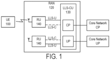
- FIG. 1 depicts an example of a RAN node 120 according to some embodiments.
- the RAN node 120 may include or be part of an eNB or a gNB.
- the RAN node 120 is illustrated as including a lower-layer split central unit ("LLS-CU") 130 with two radio units (“RUs") 140 connected to the LLS-CU 130. Although two RUs are depicted in FIG. 1 , one a RAN node may include one or more RUs.
- LLC-CU lower-layer split central unit
- RUs radio units
- the LLS-CU 130 is capable of interacting with the RUs 140 over the LLS-C control plane ("CP") and/or the LLS-U user plane ("UP") on the so-called “fronthaul.”
- the LLS-CU 130 is a logical node that includes the eNB/gNB functions as discussed below.
- the LLS-CU 130 can control the operation of the RUs 140 in some embodiments discussed herein.
- the LLS-CU 130 can communicate with the CP and UP functions of a core network on the backhaul.
- the RUs 140 can transmit and receive downlink and uplink data, respectively, to/from one or more user equipment (“UE”) nodes 100 via a wireless interface.
- UE user equipment
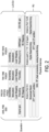
- FIG. 2 depicts a downlink (“DL") functional split between the LLS-CU and the RU for various physical layer channels and transmission modes.
- DL downlink
- iFFT iFFT
- CP addition CP addition
- digital beamforming functions may reside in the RU.
- Additional PHY functions including resource element mapping, precoding, layer mapping, modulation, scrambling, rate matching, and coding may reside in the LLS-CU, according to some embodiments.
- FIG. 3 depicts an uplink (“UL") functional split for various physical layer channels and transmission modes.
- UL uplink
- FFT frequency division multiple access
- CP removal CP removal
- digital beamforming functions may reside in the RU.
- Additional PHY functions including resource element de-mapping, equalization, de-modulation, descrambling, rate de-matching, and de-coding, can reside in the LLS-CU, according to some embodiments.
- FIG. 4 is a schematic data flow diagram that depicts data flow of control information and user data between the LLS-CU and the RU for various physical layer channels and transmission modes according to some embodiments.
- CP messages may be exchanged between an LLS-CU and an RU according to a scheduling and beamforming commands transfer procedure.
- One purpose of CP messages is to transmit data-associated control information ("DACI") required for the processing of user data.
- DACI data-associated control information
- Messages may be sent separately for DL-related commands and UL-related commands, as illustrated in FIG. 4 .
- CP messages may be sent either jointly or separately depending on the channel for which information is conveyed. For example, PUCCH and PUSCH may be bundled or not bundled into a single CP message depending on implementation.
- a LLS-CU such as a central unit and or a baseband unit
- an RU supporting 3GPP LTE and NR
- a method includes transmitting data-associated control information messages (DACI) from an LLS-CU to an RU.
- DACI data-associated control information messages
- the DACI includes information that defines how the RU should handle User Data messages that are transferred from the LLS-CU to the RU, wherein the UD-DL includes content to be transmitted over the air.
- the DACI includes controlling how data is to be received over the air and inserted into at least one User Data message transferred from the RU to the LLS-CU.
- Downlink and uplink user data messages may be referred to herein using the terms UD-DL and UD-UL, respectively.
- the UD-DL and UD-UL messages include: the corresponding identifiers (Section ID and RU_port) as the corresponding Section Type 1 message; user data format and optional compression; and 1 sample per RE, in any of the supported formats.
- one sample per resource element may be sent in a data plane message for all REs in a physical resource block ("PRB").
- PRB physical resource block
- Each sample includes a plurality of bits, for example, 30 bits.
- samples for all REs may need to be sent even when not used to carry user data.
- the LLS-CU may transmit full bitrate/bandwidth to all radios for this symbol. For that reason, the possible pooling gain may be reduced.
- FIG. 5 is a schematic data flow diagram that depicts a signal flow diagram related to DACI messages according to some embodiments.
- DACI(A) is directed to a DACI message sent from the LLS-CU to the RU with information describing a coming reception.
- the RU sends one or more UD-UL messages in correspondence with the request including samples of the received signal over the air.
- DACI(B) is directed to a DACI message sent from the LLS-CU to the RU with information describing a coming transmission.
- the LLS-CU in this embodiment is related to transmitting one or more UD-DL messages containing the information to be transmitted into the air.
- DACI(C) is directed to two different DACI messages sent from the LLS-CU to the RU with information describing a coming transmission.
- the two DACI messages describe at least one transmission method for different REs in the same symbol in the same PRB.
- the LLS-CU in this embodiment then transmits one or more UL-DL messages containing the information to be transmitted into the air, combined for the two DACI.
- FIGS. 6A-B are schematic block diagrams that depict a high level of a protocol of the DACI message and UD-UL/UD-DL messages which carry UD-UL and UD-DL, respectively.
- the DACI messages contain a common header, indicating the RU_Port_ID for the DACI, and then a variable set of Sections, each describing a coming transmission.
- the UD-UL and UD-DL messages include a common header, indicating the RU_Port_UD for the UD-xx (e.g., UD-UL and/or UD-DL) message, and then a variable set of sections, each including a section header indicating the content of the data field, and a data field, containing UD-UL or UD-DL data.
- the section header according to some embodiments also includes a Section ID to map to the corresponding Section of the DACI message and the format of the data in the data field.
- user data carried in the UD-DL message from the LLS-CU to the RU may include reference symbols that have been mapped to REs.
- the user data transferred to the RU in the UD-DL message can be compressed for transmission to the RU using a bitmap representation that indicates which samples or resource elements ("REs") should not be further transferred and which ones that should be transferred.
- REs resource elements
- REs are known to carry 0's. For a PRB with only reference symbols being transferred, most of the REs in the PRB will carry a 0, i.e. the RE will be empty.
- the protocol specification for DACI there already exists a means to signal which REs in a UD-DL message are marked as empty, namely, the reMask field.
- the DACI protocol specification indicates that REs marked as empty shall still have data samples transferred in the related UD-DL and UD-UL transmission.
- the protocol also allows for multiple DACI sections to point to the PRB(s) with different reMask sets, to allow for different control (e.g., beam forming) for the different sets of REs in the PRB(s).
- the current protocol allows for two DACI messages pointing to the same PRB for the RU_port_ID. The corresponding UD-DL and UD-UL are still combined into one packet for both those DACI sections.
- FIG. 7 is a schematic block diagram that illustrates a physical resource block ("PRB") to which data to be transmitted in the UP-DL (or UD-DL) message from the LLS-CU to the RU is mapped, where the PRB includes cell-specific reference symbols ("CRS") in predefined locations within the PRB.
- the PRB spans 14 OFDM symbols in the time dimension (horizontal axis) and 12 frequency subchannels in the frequency dimension (vertical axis).
- Each time/frequency element in the PRB corresponds to an RE of the PRB.
- the PRB includes two REs carrying CRS in symbols 0, 4, 7 and 11. In this example, all other REs in the PRB carry zeros. In general, some REs in a PRB are known to carry zeros; in PRBs in which only reference symbols are carried, most of the REs will carry a zero.
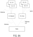
- FIGS. 8A-B are block diagrams illustrating beam forming in accordance with some embodiments herein.
- the downlink messages going to the radio unit are accumulated, concentrated and/or multiplexed before being delivered to the radio unit.
- FIG. 8B all of the downlink messages are delivered to the radio unit, which includes an accumulator functionality.
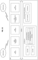
- FIG. 9 is a flow chart illustrating operations of a wireless device according to some embodiments of inventive concepts.
- the operation of FIG. 9 may be included in methods for operating a RU in a network node of a wireless communication system.
- Operations may include receiving a data-associated control information (DACI) message including a section description associated with the downlink signals and an indication of how to perform the accumulating data operation (block 900).
- DACI data-associated control information
- Some embodiments provide that a memory corresponding to the accumulator function may span multiple REs. Some of the REs may include symbols.
- Each UD-DL may populate a portion of the accumulator function memory. Data from the accumulator memory may be received and/or used by the beam former.
- the operations may include receiving, at the RU and from a LLS-CU, multiple downlink signals that include reference symbols (RS) and user data downlink (UD-DL) messages to be transmitted to a user equipment (UE) over a wireless interface (block 902).
- the downlink signals that include the RS and UD-DL messages may include independent ranges in time and/or frequency.
- Some embodiments further include determining a signaling priority of overlapping resource elements (RE) samples and/or overlapping beam forming commands.
- RE resource elements
- Operations may include accumulating received data corresponding to the plurality of downlink signals into a concentrated data format (block 904). Some embodiments include multiplexing the RS and the UD-DL in the RU (block 906). Operations may further include mapping the RE samples to a plurality of RU ports and generating a beam vector that includes a plurality of RE beam weights that correspond to respective ones of the RU ports (block 908).
- the DACI message includes a field that indicates which REs are omitted from a user plane UD-DL.
- the field may include a combination of a RE mask that indicates which of the REs a user is using and a symbol mask that indicates symbols in which the RE mask is valid.
- the DACI message includes a field that indicates a priority of a section of the PRB.
- the indication may include information that the section over-rules a previous section.
- the DACI message includes a field that indicates which of multiple REs is not included in the UD-DL message.
- the DACI message includes a field that indicates a priority of a RE sample. In some embodiments, a priority RE sample will not be overwritten by a subsequent UD-DL message.
- the DACI message includes data regarding which direction a given one of multiple RU ports will transmit in.
- FIG. 10 is a flow chart illustrating operations of a network node station according to some embodiments of inventive concepts.
- Operations may include sending, to the RU, a data-associated control information (DACI) message including a section description that instructs the RU how to accumulate the downlink signals (block 1000).
- Operations for methods of operating lower-layer split central unit (LLS-CU) in a network node of a wireless communication system include sending, without accumulating or multiplexing, to a radio unit (RU) multiple downlink signals that include reference symbols (RS) and user data downlink (UD-DL) messages to be transmitted to a user equipment (UE) over a wireless interface (block 1002).
- RS reference symbols
- UD-DL user data downlink
- the downlink signals include independent ranges in time and/or frequency.
- the DACI message includes a field that indicates which REs are omitted from a user plane UD-DL.
- the field includes a combination of a RE mask that indicates which of the REs a user is using and a symbol mask that indicates symbols in which the RE mask is valid.
- the DACI message includes a field that indicates a priority of a section of the PRB, wherein the indication includes information that the section over-rules a previous section.
- the RS and the UD-DL data to be transmitted to the user equipment are transmitted in a user data down link UD-DL message and the DACI message includes a field that indicates which of a plurality of REs is not included in the UD-DL message.
- the DACI message includes a field that indicates a priority of a RE sample and that a priority RE sample will not be overwritten by a subsequent UD-DL message.
- the DACI message includes data regarding which direction a given one of a plurality of RU ports will transmit in.
- a radio unit may collect beam widths and samples from different control and user data messages with an independent range in time and/or frequency intervals. A signaling priority of overlapping RE samples and/or overlapping beam forming commands may be determined.
- functions corresponding to the multiplexing of control and user data may be performed in the RU instead of the LLS-CU.
- Such embodiments may reduce signaling overhead and bitrate and may provide improved scaling possibilities of the LLS-CU.
- RU port inputs may be built.
- a good illustration of a RU port may include a vector multiplication.
- the RU port receives, via the DACI messages, input on the beam forming weights. Such inputs may include how to map each sample onto each transmitter branch.
- the size of this vector may be the number of transmitter branches.
- the RU port receives, from the UD-DL messages, the samples. For example, one sample may be received per RE.
- the output from the vector multiplication may thus be, per RE, a value corresponding to that transmitter branch.
- An RU may typically include many RU ports. Each of these RU ports may contribute to the value to be sent on that transmitter branch. The complete RU handling of RU ports thus become a matrix multiplication between RU port samples and beam forming weights.
- the RU could build the beam vector by looking at the DACI message PRB range in combination with beam index / beam weight / beam attributes and reMask. The RU may then apply the multiplication upon reception of the UD-DL message.
- the RU is configured to build the beam vector by looking at the DACI messages without limiting the configuration to only look the sections perfectly overlapping in case of an reMask.
- some embodiments provide that the RU may build the beam vector from any DACI.
- the reMask may be used to determine which DACI sets which RE beam weight.
- Some embodiments provide the RU fills the RE samples from many UD-DL messages. If two UD-DL messages include a sample for the same RE, the RU may provide several options for addressing this condition. A first option may include using the reMask to determine which UD-DL has the right to send on that RE. A second option may include adding the two samples together. In some embodiments, the user data UD-DL may be likely to include a 0 on that sample (the reference symbol RE), and vice versa. A third option provides including an additional field in the UD-DL indicating if the message has priority. The problem may not occur if compression is added to allow omission of unused REs.
- the RU can allow DACI messages spanning multiple symbols for user data and DACI messages spanning one symbol for reference symbols. This may reduce signal overhead.
- the DACI message for user data may then have reMask set for the symbol that do not include reference symbols, and the DACI with reference symbols may override the interpretation for that symbol.
- the separation of reference symbols and user data may be added in the DACI messages by reinterpreting the existing fields therein and by removing the strict usage of multiple overlapping sections.
- the DACI may be modified by adding a field to indicate which REs are omitted from the user plane UD-DL. In this manner, the samples for the REs may not need to be transferred.
- This field may be a combination of the reMask and a symbolMask, where the symbolMask indicates the symbols in which the reMask is valid.
- the reMask may be assumed to be 0xFFF for non-marked symbols.
- the DACI may also be modified to include a field to indicate if the section has priority.
- the field may indicate if the section over-rules a previous section. This can be used to indicate that the beam forming of a reference symbol DACI may over-ride the beam forming of the user plane DACI.
- UD-DL message can be reused as is and/or extended with more indications corresponding to the current usage.
- the DACI may further include a field to indicate which REs are no included in the UD-DL. In some embodiments, such field may provide information regarding REs that are expected in another UD-DL.
- DACI may include a field to indicate the priority of the RE samples.
- the field may indicate if these samples shall replace samples received in a previous UD-DL and thus should not be overwritten by any coming UD-DL. In some embodiments, this may be combined with a bitmap compression concept and/or interpreted in combination with the reMask of the corresponding DACI Section.
- the terms “comprise”, “comprising”, “comprises”, “include”, “including”, “includes”, “have”, “has”, “having”, or variants thereof are open-ended, and include one or more stated features, integers, elements, steps, components or functions but does not preclude the presence or addition of one or more other features, integers, elements, steps, components, functions or groups thereof.
- the common abbreviation “e.g.”, which derives from the Latin phrase “exempli gratia” may be used to introduce or specify a general example or examples of a previously mentioned item, and is not intended to be limiting of such item.
- the common abbreviation “i.e.”, which derives from the Latin phrase “id est,” may be used to specify a particular item from a more general recitation.
- Example embodiments are described herein with reference to block diagrams and/or flowchart illustrations of computer-implemented methods, apparatus (systems and/or devices) and/or computer program products. It is understood that a block of the block diagrams and/or flowchart illustrations, and combinations of blocks in the block diagrams and/or flowchart illustrations, can be implemented by computer program instructions that are performed by one or more computer circuits.
- These computer program instructions may be provided to a processor circuit of a general purpose computer circuit, special purpose computer circuit, and/or other programmable data processing circuit to produce a machine, such that the instructions, which execute via the processor of the computer and/or other programmable data processing apparatus, transform and control transistors, values stored in memory locations, and other hardware components within such circuitry to implement the functions/acts specified in the block diagrams and/or flowchart block or blocks, and thereby create means (functionality) and/or structure for implementing the functions/acts specified in the block diagrams and/or flowchart block(s).
- FIG. 14 A wireless network in accordance with some embodiments.
- a wireless network such as the example wireless network illustrated in FIG. 14 .
- the wireless network of FIG. 14 only depicts network 1406, network nodes 1460 and 1460b, and WDs 1410, 1410b, and 1410c (also referred to as mobile terminals).
- a wireless network may further include any additional elements suitable to support communication between wireless devices or between a wireless device and another communication device, such as a landline telephone, a service provider, or any other network node or end device.
- network node 1460 and wireless device (WD) 1410 are depicted with additional detail.
- the wireless network may provide communication and other types of services to one or more wireless devices to facilitate the wireless devices' access to and/or use of the services provided by, or via, the wireless network.
- the wireless network may comprise and/or interface with any type of communication, telecommunication, data, cellular, and/or radio network or other similar type of system.
- the wireless network may be configured to operate according to specific standards or other types of predefined rules or procedures.
- particular embodiments of the wireless network may implement communication standards, such as Global System for Mobile Communications (GSM), Universal Mobile Telecommunications System (UMTS), Long Term Evolution (LTE), and/or other suitable 2G, 3G, 4G, or 5G standards; wireless local area network (WLAN) standards, such as the IEEE 802.11 standards; and/or any other appropriate wireless communication standard, such as the Worldwide Interoperability for Microwave Access (WiMax), Bluetooth, Z-Wave and/or ZigBee standards.
- GSM Global System for Mobile Communications
- UMTS Universal Mobile Telecommunications System
- LTE Long Term Evolution
- WLAN wireless local area network
- WiMax Worldwide Interoperability for Microwave Access
- Bluetooth Z-Wave and/or ZigBee standards.
- Network 1406 may comprise one or more backhaul networks, core networks, IP networks, public switched telephone networks (PSTNs), packet data networks, optical networks, wide-area networks (WANs), local area networks (LANs), wireless local area networks (WLANs), wired networks, wireless networks, metropolitan area networks, and other networks to enable communication between devices.
- PSTNs public switched telephone networks
- WANs wide-area networks
- LANs local area networks
- WLANs wireless local area networks
- wired networks wireless networks, metropolitan area networks, and other networks to enable communication between devices.
- Network node 1460 and WD 1410 comprise various components described in more detail below. These components work together in order to provide network node and/or wireless device functionality, such as providing wireless connections in a wireless network.
- the wireless network may comprise any number of wired or wireless networks, network nodes, base stations, controllers, wireless devices, relay stations, and/or any other components or systems that may facilitate or participate in the communication of data and/or signals whether via wired or wireless connections.
- network node refers to equipment capable, configured, arranged and/or operable to communicate directly or indirectly with a wireless device and/or with other network nodes or equipment in the wireless network to enable and/or provide wireless access to the wireless device and/or to perform other functions (e.g., administration) in the wireless network.
- network nodes include, but are not limited to, access points (APs) (e.g., radio access points), base stations (BSs) (e.g., radio base stations, Node Bs, evolved Node Bs (eNBs) and NR NodeBs (gNBs)).
- APs access points
- BSs base stations
- eNBs evolved Node Bs
- gNBs NR NodeBs
- Base stations may be categorized based on the amount of coverage they provide (or, stated differently, their transmit power level) and may then also be referred to as femto base stations, pico base stations, micro base stations, or macro base stations.
- a base station may be a relay node or a relay donor node controlling a relay.
- a network node may also include one or more (or all) parts of a distributed radio base station such as centralized digital units and/or remote radio units (RRUs), sometimes referred to as Remote Radio Heads (RRHs). Such remote radio units may or may not be integrated with an antenna as an antenna integrated radio.
- RRUs remote radio units
- RRHs Remote Radio Heads
- Such remote radio units may or may not be integrated with an antenna as an antenna integrated radio.
- Parts of a distributed radio base station may also be referred to as nodes in a distributed antenna system (DAS).
- DAS distributed antenna system
- network nodes include multi-standard radio (MSR) equipment such as MSR BSs, network controllers such as radio network controllers (RNCs) or base station controllers (BSCs), base transceiver stations (BTSs), transmission points, transmission nodes, multi-cell/multicast coordination entities (MCEs), core network nodes (e.g., MSCs, MMEs), O&M nodes, OSS nodes, SON nodes, positioning nodes (e.g., E-SMLCs), and/or MDTs.
- MSR multi-standard radio
- RNCs radio network controllers
- BSCs base station controllers
- BTSs base transceiver stations
- transmission points transmission nodes
- MCEs multi-cell/multicast coordination entities
- core network nodes e.g., MSCs, MMEs
- O&M nodes e.g., OSS nodes, SON nodes, positioning nodes (e.g., E-SMLCs), and/or MDTs.
- network nodes may represent any suitable device (or group of devices) capable, configured, arranged, and/or operable to enable and/or provide a wireless device with access to the wireless network or to provide some service to a wireless device that has accessed the wireless network.
- network node 1460 includes processing circuitry 1470, device readable medium 1480, interface 1490, auxiliary equipment 1484, power source 1486, power circuitry 1487, and antenna 1462.
- network node 1460 illustrated in the example wireless network of FIG. 14 may represent a device that includes the illustrated combination of hardware components, other embodiments may comprise network nodes with different combinations of components. It is to be understood that a network node comprises any suitable combination of hardware and/or software needed to perform the tasks, features, functions and methods disclosed herein.
- network node 1460 may comprise multiple different physical components that make up a single illustrated component (e.g., device readable medium 1480 may comprise multiple separate hard drives as well as multiple RAM modules).
- network node 1460 may be composed of multiple physically separate components (e.g., a NodeB component and a RNC component, or a BTS component and a BSC component, etc.), which may each have their own respective components.
- network node 1460 comprises multiple separate components (e.g., BTS and BSC components)
- one or more of the separate components may be shared among several network nodes.
- a single RNC may control multiple NodeB's.
- each unique NodeB and RNC pair may in some instances be considered a single separate network node.
- network node 1460 may be configured to support multiple radio access technologies (RATs).
- RATs radio access technologies
- Network node 1460 may also include multiple sets of the various illustrated components for different wireless technologies integrated into network node 1460, such as, for example, GSM, WCDMA, LTE, NR, WiFi, or Bluetooth wireless technologies. These wireless technologies may be integrated into the same or different chip or set of chips and other components within network node 1460.
- Processing circuitry 1470 is configured to perform any determining, calculating, or similar operations (e.g., certain obtaining operations) described herein as being provided by a network node. These operations performed by processing circuitry 1470 may include processing information obtained by processing circuitry 1470 by, for example, converting the obtained information into other information, comparing the obtained information or converted information to information stored in the network node, and/or performing one or more operations based on the obtained information or converted information, and as a result of said processing making a determination.
- processing information obtained by processing circuitry 1470 by, for example, converting the obtained information into other information, comparing the obtained information or converted information to information stored in the network node, and/or performing one or more operations based on the obtained information or converted information, and as a result of said processing making a determination.
- Processing circuitry 1470 may comprise a combination of one or more of a microprocessor, controller, microcontroller, central processing unit, digital signal processor, application-specific integrated circuit, field programmable gate array, or any other suitable computing device, resource, or combination of hardware, software and/or encoded logic operable to provide, either alone or in conjunction with other network node 1460 components, such as device readable medium 1480, network node 1460 functionality.
- processing circuitry 1470 may execute instructions stored in device readable medium 1480 or in memory within processing circuitry 1470. Such functionality may include providing any of the various wireless features, functions, or benefits discussed herein.
- processing circuitry 1470 may include a system on a chip (SOC).
- SOC system on a chip
- processing circuitry 1470 may include one or more of radio frequency (RF) transceiver circuitry 1472 and baseband processing circuitry 1474.
- radio frequency (RF) transceiver circuitry 1472 and baseband processing circuitry 1474 may be on separate chips (or sets of chips), boards, or units, such as radio units and digital units.
- part or all of RF transceiver circuitry 1472 and baseband processing circuitry 1474 may be on the same chip or set of chips, boards, or units.
- processing circuitry 1470 executing instructions stored on device readable medium 1480 or memory within processing circuitry 1470.
- some or all of the functionality may be provided by processing circuitry 1470 without executing instructions stored on a separate or discrete device readable medium, such as in a hard-wired manner.
- processing circuitry 1470 can be configured to perform the described functionality. The benefits provided by such functionality are not limited to processing circuitry 1470 alone or to other components of network node 1460, but are enjoyed by network node 1460 as a whole, and/or by end users and the wireless network generally.
- Device readable medium 1480 may comprise any form of volatile or non-volatile computer readable memory including, without limitation, persistent storage, solid-state memory, remotely mounted memory, magnetic media, optical media, random access memory (RAM), read-only memory (ROM), mass storage media (for example, a hard disk), removable storage media (for example, a flash drive, a Compact Disk (CD) or a Digital Video Disk (DVD)), and/or any other volatile or non-volatile, non-transitory device readable and/or computer-executable memory devices that store information, data, and/or instructions that may be used by processing circuitry 1470.
- volatile or non-volatile computer readable memory including, without limitation, persistent storage, solid-state memory, remotely mounted memory, magnetic media, optical media, random access memory (RAM), read-only memory (ROM), mass storage media (for example, a hard disk), removable storage media (for example, a flash drive, a Compact Disk (CD) or a Digital Video Disk (DVD)), and/or any other volatile or
- Device readable medium 1480 may store any suitable instructions, data or information, including a computer program, software, an application including one or more of logic, rules, code, tables, etc. and/or other instructions capable of being executed by processing circuitry 1470 and, utilized by network node 1460.
- Device readable medium 1480 may be used to store any calculations made by processing circuitry 1470 and/or any data received via interface 1490.
- processing circuitry 1470 and device readable medium 1480 may be considered to be integrated.
- Interface 1490 is used in the wired or wireless communication of signalling and/or data between network node 1460, network 1406, and/or WDs 1410. As illustrated, interface 1490 comprises port(s)/terminal(s) 1494 to send and receive data, for example to and from network 1406 over a wired connection. Interface 1490 also includes radio front end circuitry 1492 that may be coupled to, or in certain embodiments a part of, antenna 1462. Radio front end circuitry 1492 comprises filters 1498 and amplifiers 1496. Radio front end circuitry 1492 may be connected to antenna 1462 and processing circuitry 1470. Radio front end circuitry may be configured to condition signals communicated between antenna 1462 and processing circuitry 1470.
- Radio front end circuitry 1492 may receive digital data that is to be sent out to other network nodes or WDs via a wireless connection. Radio front end circuitry 1492 may convert the digital data into a radio signal having the appropriate channel and bandwidth parameters using a combination of filters 1498 and/or amplifiers 1496. The radio signal may then be transmitted via antenna 1462. Similarly, when receiving data, antenna 1462 may collect radio signals which are then converted into digital data by radio front end circuitry 1492. The digital data may be passed to processing circuitry 1470. In other embodiments, the interface may comprise different components and/or different combinations of components.
- network node 1460 may not include separate radio front end circuitry 1492, instead, processing circuitry 1470 may comprise radio front end circuitry and may be connected to antenna 1462 without separate radio front end circuitry 1492.
- processing circuitry 1470 may comprise radio front end circuitry and may be connected to antenna 1462 without separate radio front end circuitry 1492.
- all or some of RF transceiver circuitry 1472 may be considered a part of interface 1490.
- interface 1490 may include one or more ports or terminals 1494, radio front end circuitry 1492, and RF transceiver circuitry 1472, as part of a radio unit (not shown), and interface 1490 may communicate with baseband processing circuitry 1474, which is part of a digital unit (not shown).
- Antenna 1462 may include one or more antennas, or antenna arrays, configured to send and/or receive wireless signals. Antenna 1462 may be coupled to radio front end circuitry 1490 and may be any type of antenna capable of transmitting and receiving data and/or signals wirelessly. In some embodiments, antenna 1462 may comprise one or more omni-directional, sector or panel antennas operable to transmit/receive radio signals between, for example, 2 GHz and 66 GHz. An omni-directional antenna may be used to transmit/receive radio signals in any direction, a sector antenna may be used to transmit/receive radio signals from devices within a particular area, and a panel antenna may be a line of sight antenna used to transmit/receive radio signals in a relatively straight line. In some instances, the use of more than one antenna may be referred to as MIMO. In certain embodiments, antenna 1462 may be separate from network node 1460 and may be connectable to network node 1460 through an interface or port.
- Antenna 1462, interface 1490, and/or processing circuitry 1470 may be configured to perform any receiving operations and/or certain obtaining operations described herein as being performed by a network node. Any information, data and/or signals may be received from a wireless device, another network node and/or any other network equipment. Similarly, antenna 1462, interface 1490, and/or processing circuitry 1470 may be configured to perform any transmitting operations described herein as being performed by a network node. Any information, data and/or signals may be transmitted to a wireless device, another network node and/or any other network equipment.
- Power circuitry 1487 may comprise, or be coupled to, power management circuitry and is configured to supply the components of network node 1460 with power for performing the functionality described herein. Power circuitry 1487 may receive power from power source 1486. Power source 1486 and/or power circuitry 1487 may be configured to provide power to the various components of network node 1460 in a form suitable for the respective components (e.g., at a voltage and current level needed for each respective component). Power source 1486 may either be included in, or external to, power circuitry 1487 and/or network node 1460.
- network node 1460 may be connectable to an external power source (e.g., an electricity outlet) via an input circuitry or interface such as an electrical cable, whereby the external power source supplies power to power circuitry 1487.
- power source 1486 may comprise a source of power in the form of a battery or battery pack which is connected to, or integrated in, power circuitry 1487. The battery may provide backup power should the external power source fail.
- Other types of power sources such as photovoltaic devices, may also be used.
- network node 1460 may include additional components beyond those shown in FIG. 14 that may be responsible for providing certain aspects of the network node's functionality, including any of the functionality described herein and/or any functionality necessary to support the subject matter described herein.
- network node 1460 may include user interface equipment to allow input of information into network node 1460 and to allow output of information from network node 1460. This may allow a user to perform diagnostic, maintenance, repair, and other administrative functions for network node 1460.
- wireless device refers to a device capable, configured, arranged and/or operable to communicate wirelessly with network nodes and/or other wireless devices.
- the term WD may be used interchangeably herein with user equipment (UE).
- Communicating wirelessly may involve transmitting and/or receiving wireless signals using electromagnetic waves, radio waves, infrared waves, and/or other types of signals suitable for conveying information through air.
- a WD may be configured to transmit and/or receive information without direct human interaction.
- a WD may be designed to transmit information to a network on a predetermined schedule, when triggered by an internal or external event, or in response to requests from the network.
- Examples of a WD include, but are not limited to, a smart phone, a mobile phone, a cell phone, a voice over IP (VoIP) phone, a wireless local loop phone, a desktop computer, a personal digital assistant (PDA), a wireless cameras, a gaming console or device, a music storage device, a playback appliance, a wearable terminal device, a wireless endpoint, a mobile station, a tablet, a laptop, a laptop-embedded equipment (LEE), a laptop-mounted equipment (LME), a smart device, a wireless customer-premise equipment (CPE). a vehicle-mounted wireless terminal device, etc.
- VoIP voice over IP
- PDA personal digital assistant
- PDA personal digital assistant
- gaming console or device a wireless cameras
- a gaming console or device a music storage device
- a playback appliance a wearable terminal device
- a wireless endpoint a mobile station, a tablet, a laptop, a laptop-embedded equipment (LEE), a laptop
- a WD may support device-to-device (D2D) communication, for example by implementing a 3GPP standard for sidelink communication, vehicle-to-vehicle (V2V), vehicle-to-infrastructure (V2I), vehicle-to-everything (V2X) and may in this case be referred to as a D2D communication device.
- D2D device-to-device
- V2V vehicle-to-vehicle
- V2I vehicle-to-infrastructure
- V2X vehicle-to-everything
- a WD may represent a machine or other device that performs monitoring and/or measurements, and transmits the results of such monitoring and/or measurements to another WD and/or a network node.
- the WD may in this case be a machine-to-machine (M2M) device, which may in a 3GPP context be referred to as an MTC device.
- M2M machine-to-machine
- the WD may be a UE implementing the 3GPP narrow band internet of things (NB-IoT) standard.
- NB-IoT narrow band internet of things
- machines or devices are sensors, metering devices such as power meters, industrial machinery, or home or personal appliances (e.g. refrigerators, televisions, etc.) personal wearables (e.g., watches, fitness trackers, etc.).
- a WD may represent a vehicle or other equipment that is capable of monitoring and/or reporting on its operational status or other functions associated with its operation.
- a WD as described above may represent the endpoint of a wireless connection, in which case the device may be referred to as a wireless terminal. Furthermore, a WD as described above may be mobile, in which case it may also be referred to as a mobile device or a mobile terminal.
- wireless device 1410 includes antenna 1411, interface 1414, processing circuitry 1420, device readable medium 1430, user interface equipment 1432, auxiliary equipment 1434, power source 1436 and power circuitry 1437.
- WD 1410 may include multiple sets of one or more of the illustrated components for different wireless technologies supported by WD 1410, such as, for example, GSM, WCDMA, LTE, NR, WiFi, WiMAX, or Bluetooth wireless technologies, just to mention a few. These wireless technologies may be integrated into the same or different chips or set of chips as other components within WD 1410.
- Antenna 1411 may include one or more antennas or antenna arrays, configured to send and/or receive wireless signals, and is connected to interface 1414. In certain alternative embodiments, antenna 1411 may be separate from WD 1410 and be connectable to WD 1410 through an interface or port. Antenna 1411, interface 1414, and/or processing circuitry 1420 may be configured to perform any receiving or transmitting operations described herein as being performed by a WD. Any information, data and/or signals may be received from a network node and/or another WD. In some embodiments, radio front end circuitry and/or antenna 1411 may be considered an interface.
- interface 1414 comprises radio front end circuitry 1412 and antenna 1411.
- Radio front end circuitry 1412 comprise one or more filters 1418 and amplifiers 1416.
- Radio front end circuitry 1414 is connected to antenna 1411 and processing circuitry 1420, and is configured to condition signals communicated between antenna 1411 and processing circuitry 1420.
- Radio front end circuitry 1412 may be coupled to or a part of antenna 1411.
- WD 1410 may not include separate radio front end circuitry 1412; rather, processing circuitry 1420 may comprise radio front end circuitry and may be connected to antenna 1411.
- some or all of RF transceiver circuitry 1422 may be considered a part of interface 1414.
- Radio front end circuitry 1412 may receive digital data that is to be sent out to other network nodes or WDs via a wireless connection. Radio front end circuitry 1412 may convert the digital data into a radio signal having the appropriate channel and bandwidth parameters using a combination of filters 1418 and/or amplifiers 1416. The radio signal may then be transmitted via antenna 1411. Similarly, when receiving data, antenna 1411 may collect radio signals which are then converted into digital data by radio front end circuitry 1412. The digital data may be passed to processing circuitry 1420. In other embodiments, the interface may comprise different components and/or different combinations of components.
- Processing circuitry 1420 may comprise a combination of one or more of a microprocessor, controller, microcontroller, central processing unit, digital signal processor, application-specific integrated circuit, field programmable gate array, or any other suitable computing device, resource, or combination of hardware, software, and/or encoded logic operable to provide, either alone or in conjunction with other WD 1410 components, such as device readable medium 1430, WD 1410 functionality. Such functionality may include providing any of the various wireless features or benefits discussed herein.
- processing circuitry 1420 may execute instructions stored in device readable medium 1430 or in memory within processing circuitry 1420 to provide the functionality disclosed herein.
- processing circuitry 1420 includes one or more of RF transceiver circuitry 1422, baseband processing circuitry 1424, and application processing circuitry 1426.
- the processing circuitry may comprise different components and/or different combinations of components.
- processing circuitry 1420 of WD 1410 may comprise a SOC.
- RF transceiver circuitry 1422, baseband processing circuitry 1424, and application processing circuitry 1426 may be on separate chips or sets of chips.
- part or all of baseband processing circuitry 1424 and application processing circuitry 1426 may be combined into one chip or set of chips, and RF transceiver circuitry 1422 may be on a separate chip or set of chips.
- part or all of RF transceiver circuitry 1422 and baseband processing circuitry 1424 may be on the same chip or set of chips, and application processing circuitry 1426 may be on a separate chip or set of chips.
- part or all of RF transceiver circuitry 1422, baseband processing circuitry 1424, and application processing circuitry 1426 may be combined in the same chip or set of chips.
- RF transceiver circuitry 1422 may be a part of interface 1414.
- RF transceiver circuitry 1422 may condition RF signals for processing circuitry 1420.
- processing circuitry 1420 executing instructions stored on device readable medium 1430, which in certain embodiments may be a computer-readable storage medium.
- some or all of the functionality may be provided by processing circuitry 1420 without executing instructions stored on a separate or discrete device readable storage medium, such as in a hard-wired manner.
- processing circuitry 1420 can be configured to perform the described functionality. The benefits provided by such functionality are not limited to processing circuitry 1420 alone or to other components of WD 1410, but are enjoyed by WD 1410 as a whole, and/or by end users and the wireless network generally.
- Processing circuitry 1420 may be configured to perform any determining, calculating, or similar operations (e.g., certain obtaining operations) described herein as being performed by a WD. These operations, as performed by processing circuitry 1420, may include processing information obtained by processing circuitry 1420 by, for example, converting the obtained information into other information, comparing the obtained information or converted information to information stored by WD 1410, and/or performing one or more operations based on the obtained information or converted information, and as a result of said processing making a determination.
- processing information obtained by processing circuitry 1420 by, for example, converting the obtained information into other information, comparing the obtained information or converted information to information stored by WD 1410, and/or performing one or more operations based on the obtained information or converted information, and as a result of said processing making a determination.
- Device readable medium 1430 may be operable to store a computer program, software, an application including one or more of logic, rules, code, tables, etc. and/or other instructions capable of being executed by processing circuitry 1420.
- Device readable medium 1430 may include computer memory (e.g., Random Access Memory (RAM) or Read Only Memory (ROM)), mass storage media (e.g., a hard disk), removable storage media (e.g., a Compact Disk (CD) or a Digital Video Disk (DVD)), and/or any other volatile or non-volatile, non-transitory device readable and/or computer executable memory devices that store information, data, and/or instructions that may be used by processing circuitry 1420.
- RAM Random Access Memory
- ROM Read Only Memory
- mass storage media e.g., a hard disk
- removable storage media e.g., a Compact Disk (CD) or a Digital Video Disk (DVD)
- processing circuitry 1420 and device readable medium 1430 may be considered to be integrated.
- User interface equipment 1432 may provide components that allow for a human user to interact with WD 1410. Such interaction may be of many forms, such as visual, audial, tactile, etc. User interface equipment 1432 may be operable to produce output to the user and to allow the user to provide input to WD 1410. The type of interaction may vary depending on the type of user interface equipment 1432 installed in WD 1410.
- WD 1410 is a smart phone
- the interaction may be via a touch screen
- WD 1410 is a smart meter
- the interaction may be through a screen that provides usage (e.g., the number of gallons used) or a speaker that provides an audible alert (e.g., if smoke is detected).
- User interface equipment 1432 may include input interfaces, devices and circuits, and output interfaces, devices and circuits. User interface equipment 1432 is configured to allow input of information into WD 1410, and is connected to processing circuitry 1420 to allow processing circuitry 1420 to process the input information.
- User interface equipment 1432 may include, for example, a microphone, a proximity or other sensor, keys/buttons, a touch display, one or more cameras, a USB port, or other input circuitry. User interface equipment 1432 is also configured to allow output of information from WD 1410, and to allow processing circuitry 1420 to output information from WD 1410. User interface equipment 1432 may include, for example, a speaker, a display, vibrating circuitry, a USB port, a headphone interface, or other output circuitry. Using one or more input and output interfaces, devices, and circuits, of user interface equipment 1432, WD 1410 may communicate with end users and/or the wireless network, and allow them to benefit from the functionality described herein.
- Auxiliary equipment 1434 is operable to provide more specific functionality which may not be generally performed by WDs. This may comprise specialized sensors for doing measurements for various purposes, interfaces for additional types of communication such as wired communications etc. The inclusion and type of components of auxiliary equipment 1434 may vary depending on the embodiment and/or scenario.
- Power source 1436 may, in some embodiments, be in the form of a battery or battery pack. Other types of power sources, such as an external power source (e.g., an electricity outlet), photovoltaic devices or power cells, may also be used.
- WD 1410 may further comprise power circuitry 1437 for delivering power from power source 1436 to the various parts of WD 1410 which need power from power source 1436 to carry out any functionality described or indicated herein.
- Power circuitry 1437 may in certain embodiments comprise power management circuitry.
- Power circuitry 1437 may additionally or alternatively be operable to receive power from an external power source; in which case WD 1410 may be connectable to the external power source (such as an electricity outlet) via input circuitry or an interface such as an electrical power cable.
- Power circuitry 1437 may also in certain embodiments be operable to deliver power from an external power source to power source 1436. This may be, for example, for the charging of power source 1436. Power circuitry 1437 may perform any formatting, converting, or other modification to the power from power source 1436 to make the power suitable for the respective components of WD 1410 to which power is supplied.
- FIG. 15 User Equipment in accordance with some embodiments
- FIG. 15 illustrates one embodiment of a UE in accordance with various aspects described herein.
- a user equipment or UE may not necessarily have a user in the sense of a human user who owns and/or operates the relevant device.
- a UE may represent a device that is intended for sale to, or operation by, a human user but which may not, or which may not initially, be associated with a specific human user (e.g., a smart sprinkler controller).
- a UE may represent a device that is not intended for sale to, or operation by, an end user but which may be associated with or operated for the benefit of a user (e.g., a smart power meter).
- UE 15200 may be any UE identified by the 3rd Generation Partnership Project (3GPP), including a NB-IoT UE, a machine type communication (MTC) UE, and/or an enhanced MTC (eMTC) UE.
- UE 1500 as illustrated in FIG. 15 , is one example of a WD configured for communication in accordance with one or more communication standards promulgated by the 3rd Generation Partnership Project (3GPP), such as 3GPP's GSM, UMTS, LTE, and/or 5G standards.
- 3GPP 3rd Generation Partnership Project
- the term WD and UE may be used interchangeable. Accordingly, although FIG. 15 is a UE, the components discussed herein are equally applicable to a WD, and vice-versa.
- UE 1500 includes processing circuitry 1501 that is operatively coupled to input/output interface 1505, radio frequency (RF) interface 1509, network connection interface 1511, memory 1515 including random access memory (RAM) 1517, read-only memory (ROM) 1519, and storage medium 1521 or the like, communication subsystem 1531, power source 1533, and/or any other component, or any combination thereof.
- Storage medium 1521 includes operating system 1523, application program 1525, and data 1527. In other embodiments, storage medium 1521 may include other similar types of information.
- Certain UEs may utilize all of the components shown in FIG. 15 , or only a subset of the components. The level of integration between the components may vary from one UE to another UE. Further, certain UEs may contain multiple instances of a component, such as multiple processors, memories, transceivers, transmitters, receivers, etc.
- processing circuitry 1501 may be configured to process computer instructions and data.
- Processing circuitry 1501 may be configured to implement any sequential state machine operative to execute machine instructions stored as machine-readable computer programs in the memory, such as one or more hardware-implemented state machines (e.g., in discrete logic, FPGA, ASIC, etc.); programmable logic together with appropriate firmware; one or more stored program, general-purpose processors, such as a microprocessor or Digital Signal Processor (DSP), together with appropriate software; or any combination of the above.
- the processing circuitry 1501 may include two central processing units (CPUs). Data may be information in a form suitable for use by a computer.
- input/output interface 1505 may be configured to provide a communication interface to an input device, output device, or input and output device.
- UE 1500 may be configured to use an output device via input/output interface 1505.
- An output device may use the same type of interface port as an input device.
- a USB port may be used to provide input to and output from UE 1500.
- the output device may be a speaker, a sound card, a video card, a display, a monitor, a printer, an actuator, an emitter, a smartcard, another output device, or any combination thereof.
- UE 1500 may be configured to use an input device via input/output interface 1505 to allow a user to capture information into UE 1500.
- the input device may include a touch-sensitive or presence-sensitive display, a camera (e.g., a digital camera, a digital video camera, a web camera, etc.), a microphone, a sensor, a mouse, a trackball, a directional pad, a trackpad, a scroll wheel, a smartcard, and the like.
- the presence-sensitive display may include a capacitive or resistive touch sensor to sense input from a user.
- a sensor may be, for instance, an accelerometer, a gyroscope, a tilt sensor, a force sensor, a magnetometer, an optical sensor, a proximity sensor, another like sensor, or any combination thereof.
- the input device may be an accelerometer, a magnetometer, a digital camera, a microphone, and an optical sensor.
- RF interface 1509 may be configured to provide a communication interface to RF components such as a transmitter, a receiver, and an antenna.
- Network connection interface 1511 may be configured to provide a communication interface to network 1543a.
- Network 1543a may encompass wired and/or wireless networks such as a local-area network (LAN), a wide-area network (WAN), a computer network, a wireless network, a telecommunications network, another like network or any combination thereof.
- network 1543a may comprise a Wi-Fi network.
- Network connection interface 1511 may be configured to include a receiver and a transmitter interface used to communicate with one or more other devices over a communication network according to one or more communication protocols, such as Ethernet, TCP/IP, SONET, ATM, or the like.
- Network connection interface 1511 may implement receiver and transmitter functionality appropriate to the communication network links (e.g., optical, electrical, and the like). The transmitter and receiver functions may share circuit components, software or firmware, or alternatively may be implemented separately.
- RAM 1517 may be configured to interface via bus 1502 to processing circuitry 1501 to provide storage or caching of data or computer instructions during the execution of software programs such as the operating system, application programs, and device drivers.
- ROM 1519 may be configured to provide computer instructions or data to processing circuitry 1501.
- ROM 1519 may be configured to store invariant low-level system code or data for basic system functions such as basic input and output (I/O), startup, or reception of keystrokes from a keyboard that are stored in a non-volatile memory.
- Storage medium 1521 may be configured to include memory such as RAM, ROM, programmable read-only memory (PROM), erasable programmable read-only memory (EPROM), electrically erasable programmable read-only memory (EEPROM), magnetic disks, optical disks, floppy disks, hard disks, removable cartridges, or flash drives.
- storage medium 1521 may be configured to include operating system 1523, application program 1525 such as a web browser application, a widget or gadget engine or another application, and data file 1527.
- Storage medium 1521 may store, for use by UE 1500, any of a variety of various operating systems or combinations of operating systems.
- Storage medium 1521 may be configured to include a number of physical drive units, such as redundant array of independent disks (RAID), floppy disk drive, flash memory, USB flash drive, external hard disk drive, thumb drive, pen drive, key drive, high-density digital versatile disc (HD-DVD) optical disc drive, internal hard disk drive, Blu-Ray optical disc drive, holographic digital data storage (HDDS) optical disc drive, external mini-dual in-line memory module (DIMM), synchronous dynamic random access memory (SDRAM), external micro-DIMM SDRAM, smartcard memory such as a subscriber identity module or a removable user identity (SIM/RUIM) module, other memory, or any combination thereof.
- RAID redundant array of independent disks
- HD-DVD high-density digital versatile disc
- HDDS holographic digital data storage
- DIMM external mini-dual in-line memory module
- SDRAM synchronous dynamic random access memory
- SDRAM synchronous dynamic random access memory
- smartcard memory such as a subscriber identity module or a removable user
- Storage medium 1521 may allow UE 1500 to access computer-executable instructions, application programs or the like, stored on transitory or non-transitory memory media, to off-load data, or to upload data.
- An article of manufacture, such as one utilizing a communication system may be tangibly embodied in storage medium 1521, which may comprise a device readable medium.
- processing circuitry 1501 may be configured to communicate with network 1543b using communication subsystem 1531.
- Network 1543a and network 1543b may be the same network or networks or different network or networks.
- Communication subsystem 1531 may be configured to include one or more transceivers used to communicate with network 1543b.
- communication subsystem 1531 may be configured to include one or more transceivers used to communicate with one or more remote transceivers of another device capable of wireless communication such as another WD, UE, or base station of a radio access network (RAN) according to one or more communication protocols, such as IEEE 802.15, CDMA, WCDMA, GSM, LTE, UTRAN, WiMax, or the like.
- RAN radio access network
- Each transceiver may include transmitter 1533 and/or receiver 1535 to implement transmitter or receiver functionality, respectively, appropriate to the RAN links (e.g., frequency allocations and the like). Further, transmitter 1533 and receiver 1535 of each transceiver may share circuit components, software or firmware, or alternatively may be implemented separately.
- the communication functions of communication subsystem 1531 may include data communication, voice communication, multimedia communication, short-range communications such as Bluetooth, near-field communication, location-based communication such as the use of the global positioning system (GPS) to determine a location, another like communication function, or any combination thereof.
- communication subsystem 1531 may include cellular communication, Wi-Fi communication, Bluetooth communication, and GPS communication.
- Network 1543b may encompass wired and/or wireless networks such as a local-area network (LAN), a wide-area network (WAN), a computer network, a wireless network, a telecommunications network, another like network or any combination thereof.
- network 1543b may be a cellular network, a Wi-Fi network, and/or a near-field network.
- Power source 1513 may be configured to provide alternating current (AC) or direct current (DC) power to components of UE 1500.
- communication subsystem 1531 may be configured to include any of the components described herein.
- processing circuitry 1501 may be configured to communicate with any of such components over bus 1502.
- any of such components may be represented by program instructions stored in memory that when executed by processing circuitry 1501 perform the corresponding functions described herein.
- the functionality of any of such components may be partitioned between processing circuitry 1501 and communication subsystem 1531.
- the non-computationally intensive functions of any of such components may be implemented in software or firmware and the computationally intensive functions may be implemented in hardware.
- FIG. 16 Virtualization environment in accordance with some embodiments
- FIG. 16 is a schematic block diagram illustrating a virtualization environment 1600 in which functions implemented by some embodiments may be virtualized.
- virtualizing means creating virtual versions of apparatuses or devices which may include virtualizing hardware platforms, storage devices and networking resources.
- virtualization can be applied to a node (e.g., a virtualized base station or a virtualized radio access node) or to a device (e.g., a UE, a wireless device or any other type of communication device) or components thereof and relates to an implementation in which at least a portion of the functionality is implemented as one or more virtual components (e.g., via one or more applications, components, functions, virtual machines or containers executing on one or more physical processing nodes in one or more networks).
- a node e.g., a virtualized base station or a virtualized radio access node
- a device e.g., a UE, a wireless device or any other type of communication device
- some or all of the functions described herein may be implemented as virtual components executed by one or more virtual machines implemented in one or more virtual environments 1600 hosted by one or more of hardware nodes 1630. Further, in embodiments in which the virtual node is not a radio access node or does not require radio connectivity (e.g., a core network node), then the network node may be entirely virtualized.
- the functions may be implemented by one or more applications 1620 (which may alternatively be called software instances, virtual appliances, network functions, virtual nodes, virtual network functions, etc.) operative to implement some of the features, functions, and/or benefits of some of the embodiments disclosed herein.
- Applications 1620 are run in virtualization environment 1600 which provides hardware 1630 comprising processing circuitry 1660 and memory 1690.
- Memory 1690 contains instructions 1695 executable by processing circuitry 1660 whereby application 1620 is operative to provide one or more of the features, benefits, and/or functions disclosed herein.
- Virtualization environment 1600 comprises general-purpose or special-purpose network hardware devices 1630 comprising a set of one or more processors or processing circuitry 1660, which may be commercial off-the-shelf (COTS) processors, dedicated Application Specific Integrated Circuits (ASICs), or any other type of processing circuitry including digital or analog hardware components or special purpose processors.
- processors or processing circuitry 1660 which may be commercial off-the-shelf (COTS) processors, dedicated Application Specific Integrated Circuits (ASICs), or any other type of processing circuitry including digital or analog hardware components or special purpose processors.
- Each hardware device may comprise memory 1690-1 which may be non-persistent memory for temporarily storing instructions 1695 or software executed by processing circuitry 1660.
- Each hardware device may comprise one or more network interface controllers (NICs) 1670, also known as network interface cards, which include physical network interface 1680.
- NICs network interface controllers
- Each hardware device may also include non-transitory, persistent, machine-readable storage media 1690-2 having stored therein software 1695 and/or instructions executable by processing circuitry 1660.
- Software 1695 may include any type of software including software for instantiating one or more virtualization layers 1650 (also referred to as hypervisors), software to execute virtual machines 1640 as well as software allowing it to execute functions, features and/or benefits described in relation with some embodiments described herein.
- Virtual machines 1640 comprise virtual processing, virtual memory, virtual networking or interface and virtual storage, and may be run by a corresponding virtualization layer 1650 or hypervisor. Different embodiments of the instance of virtual appliance 1620 may be implemented on one or more of virtual machines 1640, and the implementations may be made in different ways.
- processing circuitry 1660 executes software 1695 to instantiate the hypervisor or virtualization layer 1650, which may sometimes be referred to as a virtual machine monitor (VMM).
- VMM virtual machine monitor
- Virtualization layer 1650 may present a virtual operating platform that appears like networking hardware to virtual machine 1640.
- hardware 1630 may be a standalone network node with generic or specific components. Hardware 1630 may comprise antenna 16225 and may implement some functions via virtualization. Alternatively, hardware 1630 may be part of a larger cluster of hardware (e.g. such as in a data center or customer premise equipment (CPE)) where many hardware nodes work together and are managed via management and orchestration (MANO) 16100, which, among others, oversees lifecycle management of applications 1620.
- CPE customer premise equipment
- MANO management and orchestration
- NFV network function virtualization
- NFV may be used to consolidate many network equipment types onto industry standard high volume server hardware, physical switches, and physical storage, which can be located in data centers, and customer premise equipment.
- virtual machine 1640 may be a software implementation of a physical machine that runs programs as if they were executing on a physical, non-virtualized machine.
- Each of virtual machines 1640, and that part of hardware 1630 that executes that virtual machine be it hardware dedicated to that virtual machine and/or hardware shared by that virtual machine with others of the virtual machines 1640, forms a separate virtual network elements (VNE).
- VNE virtual network elements
- VNF Virtual Network Function
- one or more radio units 16200 that each include one or more transmitters 16220 and one or more receivers 16210 may be coupled to one or more antennas 16225.
- Radio units 16200 may communicate directly with hardware nodes 1630 via one or more appropriate network interfaces and may be used in combination with the virtual components to provide a virtual node with radio capabilities, such as a radio access node or a base station.
- control system 16230 which may alternatively be used for communication between the hardware nodes 1630 and radio units 16200.
- FIG. 17 Telecommunication network connected via an intermediate network to a host computer in accordance with some embodiments.
- a communication system includes telecommunication network 1710, such as a 3GPP-type cellular network, which comprises access network 1711, such as a radio access network, and core network 1714.
- Access network 1711 comprises a plurality of base stations 1712a, 1712b, 1712c, such as NBs, eNBs, gNBs or other types of wireless access points, each defining a corresponding coverage area 1713a, 1713b, 1713c.
- Each base station 1712a, 1712b, 1712c is connectable to core network 1714 over a wired or wireless connection 1715.
- a first UE 1791 located in coverage area 1713c is configured to wirelessly connect to, or be paged by, the corresponding base station 1712c.
- a second UE 1792 in coverage area 1713a is wirelessly connectable to the corresponding base station 1712a. While a plurality of UEs 1791, 1792 are illustrated in this example, the disclosed embodiments are equally applicable to a situation where a sole UE is in the coverage area or where a sole UE is connecting to the corresponding base station 1712.
- Telecommunication network 1710 is itself connected to host computer 1730, which may be embodied in the hardware and/or software of a standalone server, a cloud-implemented server, a distributed server or as processing resources in a server farm.
- Host computer 1730 may be under the ownership or control of a service provider, or may be operated by the service provider or on behalf of the service provider.
- Connections 1721 and 1722 between telecommunication network 1710 and host computer 1730 may extend directly from core network 1714 to host computer 1730 or may go via an optional intermediate network 1720.
- Intermediate network 1720 may be one of, or a combination of more than one of, a public, private or hosted network; intermediate network 1720, if any, may be a backbone network or the Internet; in particular, intermediate network 1720 may comprise two or more sub-networks (not shown).
- the communication system of FIG. 17 as a whole enables connectivity between the connected UEs 1791, 1792 and host computer 1730.
- the connectivity may be described as an over-the-top (OTT) connection 1750.
- Host computer 1730 and the connected UEs 1791, 1792 are configured to communicate data and/or signaling via OTT connection 1750, using access network 1711, core network 1714, any intermediate network 1720 and possible further infrastructure (not shown) as intermediaries.
- OTT connection 1750 may be transparent in the sense that the participating communication devices through which OTT connection 1750 passes are unaware of routing of uplink and downlink communications.
- base station 1712 may not or need not be informed about the past routing of an incoming downlink communication with data originating from host computer 1730 to be forwarded (e.g., handed over) to a connected UE 1791. Similarly, base station 1712 need not be aware of the future routing of an outgoing uplink communication originating from the UE 1791 towards the host computer 1730.
- FIG. 18 Host computer communicating via a base station with a user equipment over a partially wireless connection in accordance with some embodiments.
- host computer 1810 comprises hardware 1815 including communication interface 1816 configured to set up and maintain a wired or wireless connection with an interface of a different communication device of communication system 1800.
- Host computer 1810 further comprises processing circuitry 1818, which may have storage and/or processing capabilities.
- processing circuitry 1818 may comprise one or more programmable processors, application-specific integrated circuits, field programmable gate arrays or combinations of these (not shown) adapted to execute instructions.
- Host computer 1810 further comprises software 1811, which is stored in or accessible by host computer 1810 and executable by processing circuitry 1818.
- Software 1811 includes host application 1812.
- Host application 1812 may be operable to provide a service to a remote user, such as UE 1830 connecting via OTT connection 1850 terminating at UE 1830 and host computer 1810. In providing the service to the remote user, host application 1812 may provide user data which is transmitted using OTT connection 1850.
- Communication system 1800 further includes base station 1820 provided in a telecommunication system and comprising hardware 1825 enabling it to communicate with host computer 1810 and with UE 1830.
- Hardware 1825 may include communication interface 1826 for setting up and maintaining a wired or wireless connection with an interface of a different communication device of communication system 1800, as well as radio interface 1827 for setting up and maintaining at least wireless connection 1870 with UE 1830 located in a coverage area (not shown in FIG. 18 ) served by base station 1820.
- Communication interface 1826 may be configured to facilitate connection 1860 to host computer 1810. Connection 1860 may be direct or it may pass through a core network (not shown in FIG. 18 ) of the telecommunication system and/or through one or more intermediate networks outside the telecommunication system.
- hardware 1825 of base station 1820 further includes processing circuitry 1828, which may comprise one or more programmable processors, application-specific integrated circuits, field programmable gate arrays or combinations of these (not shown) adapted to execute instructions.
- Base station 1820 further has software 1821 stored internally or accessible via an external connection.
- Communication system 1800 further includes UE 1830 already referred to. Its hardware 1835 may include radio interface 1837 configured to set up and maintain wireless connection 1870 with a base station serving a coverage area in which UE 1830 is currently located. Hardware 1835 of UE 1830 further includes processing circuitry 1838, which may comprise one or more programmable processors, application-specific integrated circuits, field programmable gate arrays or combinations of these (not shown) adapted to execute instructions.
- UE 1830 further comprises software 1831, which is stored in or accessible by UE 1830 and executable by processing circuitry 1838.
- Software 1831 includes client application 1832. Client application 1832 may be operable to provide a service to a human or non-human user via UE 1830, with the support of host computer 1810.
- an executing host application 1812 may communicate with the executing client application 1832 via OTT connection 1850 terminating at UE 1830 and host computer 1810.
- client application 1832 may receive request data from host application 1812 and provide user data in response to the request data.
- OTT connection 1850 may transfer both the request data and the user data.
- Client application 1832 may interact with the user to generate the user data that it provides.
- host computer 1810, base station 1820 and UE 1830 illustrated in FIG. 18 may be similar or identical to host computer 1730, one of base stations 1712a, 1712b, 1712c and one of UEs 1791, 1792 of FIG. 17 , respectively.
- the inner workings of these entities may be as shown in FIG. 18 and independently, the surrounding network topology may be that of FIG. 17 .
- OTT connection 1850 has been drawn abstractly to illustrate the communication between host computer 1810 and UE 1830 via base station 1820, without explicit reference to any intermediary devices and the precise routing of messages via these devices.
- Network infrastructure may determine the routing, which it may be configured to hide from UE 1830 or from the service provider operating host computer 1810, or both. While OTT connection 1850 is active, the network infrastructure may further take decisions by which it dynamically changes the routing (e.g., on the basis of load balancing consideration or reconfiguration of the network).
- Wireless connection 1870 between UE 1830 and base station 1820 is in accordance with the teachings of the embodiments described throughout this disclosure.
- One or more of the various embodiments may improve the performance of OTT services provided to UE 1830 using OTT connection 1850, in which wireless connection 1870 forms the last segment. More precisely, the teachings of these embodiments may improve the deblock filtering for video processing and thereby provide benefits such as improved video encoding and/or decoding.
- a measurement procedure may be provided for the purpose of monitoring data rate, latency and other factors on which the one or more embodiments improve.
- the measurement procedure and/or the network functionality for reconfiguring OTT connection 1850 may be implemented in software 1811 and hardware 1815 of host computer 1810 or in software 1831 and hardware 1835 of UE 1830, or both.
- sensors (not shown) may be deployed in or in association with communication devices through which OTT connection 1850 passes; the sensors may participate in the measurement procedure by supplying values of the monitored quantities exemplified above, or supplying values of other physical quantities from which software 1811, 1831 may compute or estimate the monitored quantities.
- the reconfiguring of OTT connection 1850 may include message format, retransmission settings, preferred routing etc.; the reconfiguring need not affect base station 1820, and it may be unknown or imperceptible to base station 1820. Such procedures and functionalities may be known and practiced in the art.
- measurements may involve proprietary UE signaling facilitating host computer 1810's measurements of throughput, propagation times, latency and the like.
- the measurements may be implemented in that software 1811 and 1831 causes messages to be transmitted, in particular empty or 'dummy' messages, using OTT connection 1850 while it monitors propagation times, errors etc.
- FIG. 19 Methods implemented in a communication system including a host computer, a base station and a user equipment in accordance with some embodiments.
- FIG. 19 is a flowchart illustrating a method implemented in a communication system, in accordance with one embodiment.
- the communication system includes a host computer, a base station and a UE which may be those described with reference to Figures 17 and 18 .
- the host computer provides user data.
- substep 1911 (which may be optional) of step 1910, the host computer provides the user data by executing a host application.
- the host computer initiates a transmission carrying the user data to the UE.
- the base station transmits to the UE the user data which was carried in the transmission that the host computer initiated, in accordance with the teachings of the embodiments described throughout this disclosure.
- the UE executes a client application associated with the host application executed by the host computer.
- FIG. 20 Methods implemented in a communication system including a host computer, a base station and a user equipment in accordance with some embodiments.
- FIG. 20 is a flowchart illustrating a method implemented in a communication system, in accordance with one embodiment.
- the communication system includes a host computer, a base station and a UE which may be those described with reference to Figures 17 and 18 .
- the host computer provides user data.
- the host computer provides the user data by executing a host application.
- the host computer initiates a transmission carrying the user data to the UE.
- the transmission may pass via the base station, in accordance with the teachings of the embodiments described throughout this disclosure.
- step 2030 (which may be optional), the UE receives the user data carried in the transmission.
- FIG. 21 Methods implemented in a communication system including a host computer, a base station and a user equipment in accordance with some embodiments.
- FIG. 21 is a flowchart illustrating a method implemented in a communication system, in accordance with one embodiment.
- the communication system includes a host computer, a base station and a UE which may be those described with reference to Figures 17 and 18 .
- the UE receives input data provided by the host computer.
- the UE provides user data.
- substep 2121 (which may be optional) of step 2120, the UE provides the user data by executing a client application.
- substep 2111 (which may be optional) of step 2110, the UE executes a client application which provides the user data in reaction to the received input data provided by the host computer.
- the executed client application may further consider user input received from the user.
- the UE initiates, in substep 2130 (which may be optional), transmission of the user data to the host computer.
- step 2140 of the method the host computer receives the user data transmitted from the UE, in accordance with the teachings of the embodiments described throughout this disclosure.
- FIG. 22 Methods implemented in a communication system including a host computer, a base station and a user equipment in accordance with some embodiments.
- FIG. 22 is a flowchart illustrating a method implemented in a communication system, in accordance with one embodiment.
- the communication system includes a host computer, a base station and a UE which may be those described with reference to Figures 17 and 18 .
- the base station receives user data from the UE.
- the base station initiates transmission of the received user data to the host computer.
- the host computer receives the user data carried in the transmission initiated by the base station.
- any appropriate steps, methods, features, functions, or benefits disclosed herein may be performed through one or more functional units or modules of one or more virtual apparatuses.
- Each virtual apparatus may comprise a number of these functional units.
- These functional units may be implemented via processing circuitry, which may include one or more microprocessor or microcontrollers, as well as other digital hardware, which may include digital signal processors (DSPs), special-purpose digital logic, and the like.
- the processing circuitry may be configured to execute program code stored in memory, which may include one or several types of memory such as read-only memory (ROM), random-access memory (RAM), cache memory, flash memory devices, optical storage devices, etc.
- Program code stored in memory includes program instructions for executing one or more telecommunications and/or data communications protocols as well as instructions for carrying out one or more of the techniques described herein.
- the processing circuitry may be used to cause the respective functional unit to perform corresponding functions according one or more embodiments of the present disclosure.
- the term unit may have conventional meaning in the field of electronics, electrical devices and/or electronic devices and may include, for example, electrical and/or electronic circuitry, devices, modules, processors, memories, logic solid state and/or discrete devices, computer programs or instructions for carrying out respective tasks, procedures, computations, outputs, and/or displaying functions, and so on, as such as those that are described herein.
Landscapes
- Engineering & Computer Science (AREA)
- Signal Processing (AREA)
- Computer Networks & Wireless Communication (AREA)
- Mobile Radio Communication Systems (AREA)
Claims (22)
- Verfahren zum Betreiben einer Funkeinheit, RU, in einem Netzwerkknoten eines Drahtloskommunikationssystems, umfassend:Empfangen (902) einer Mehrzahl von Downlink-Signalen, die Referenzsymbole, RS, und Benutzerdaten-Downlink-Nachrichten, UD-DL-Nachrichten, umfassen, die über eine drahtlose Schnittstelle an eine Benutzereinrichtung, UE, gesendet werden sollen, an der Funkeinheit und von einer zentralen Lower-Layer-Split-Einheit, LLS-CU,Akkumulieren (904) von empfangenen Daten, die der Mehrzahl von Downlink-Signalen entsprechen, zu einem konzentrierten Datenformat; undEmpfangen (900) einer Nachricht datenassoziierter Steuerinformationen, DACI, die eine Abschnittsbeschreibung umfasst, die mit der Mehrzahl von Downlink-Signalen assoziiert ist, wobei die DACI-Nachricht eine Angabe dessen umfasst, wie die Datenakkumulationsoperation durchzuführen ist.
- Verfahren nach Anspruch 1, wobei die Mehrzahl von Downlink-Signalen, die die RS und die UD-DL-Nachrichten umfasst, zeitlich und/oder frequenzmäßig unabhängige Bereiche umfasst, wobei das Verfahren ferner ein Bestimmen einer Signalisierungspriorität überlappender Ressourcenelement-Abtastwerte, RE-Abtastwerte, und/oder überlappender Strahlformungsbefehle umfasst.
- Verfahren nach einem der Ansprüche 1 bis 2, ferner umfassend ein Multiplexen (906) der RS und der UD-DL in der RU.
- Verfahren nach einem der Ansprüche 2 bis 3, ferner umfassend ein Zuordnen (908) der RE-Abtastwerte zu einer Mehrzahl von RU-Ports und Erzeugen eines Strahlvektors, der eine Mehrzahl von RE-Strahlgewichten umfasst, die jeweiligen der Mehrzahl von RU-Ports entsprechen.
- Verfahren nach einem der Ansprüche 1 bis 4, wobei die DACI-Nachricht ein Feld umfasst, das angibt, welche REs von einer UD-DL der Benutzerebene weggelassen werden, wobei das Feld eine Kombination aus einer RE-Maske, die angibt, welches der REs ein Benutzer verwendet, und einer Symbolmaske umfasst, die Symbole angibt, in denen die RE-Maske gültig ist.
- Verfahren nach einem der Ansprüche 1 bis 5, wobei die DACI-Nachricht ein Feld umfasst, das eine Priorität eines Abschnitts eines physikalischen Ressourcenblocks, PRB, angibt, wobei die Angabe Informationen umfasst, dass der Abschnitt einen vorherigen Abschnitt außer Kraft setzt.
- Verfahren nach einem der Ansprüche 1 bis 6, wobei die DACI-Nachricht ein Feld umfasst, das angibt, welches einer Mehrzahl von REs nicht in der UD-DL-Nachricht umfasst ist.
- Verfahren nach einem der Ansprüche 1 bis 7, wobei die DACI-Nachricht ein Feld umfasst, das eine Priorität eines RE-Abtastwerts angibt, wobei ein RE-Abtastwert mit Priorität von einer nachfolgenden UD-DL-Nachricht nicht überschrieben wird.
- Verfahren nach einem der Ansprüche 1 bis 8, wobei die DACI-Nachricht Daten hinsichtlich dessen umfasst, in welcher Richtung ein gegebener von einer Mehrzahl von RU-Ports senden wird.
- Funkeinheit, RU, in einem Netzwerkknoten eines Drahtloskommunikationssystems, umfassend:eine Prozessorschaltung;einen Sendeempfänger, der mit der Prozessorschaltung gekoppelt ist und der zum Kommunizieren mit einer zentralen Lower-Layer-Split-Einheit, LLS-CU, konfiguriert ist; undeinen Speicher, der mit der Prozessorschaltung gekoppelt ist, wobei der Speicher maschinenlesbare Programmanweisungen umfasst, die bei Ausführung durch die Prozessorschaltung die RU zum Durchführen von Operationen veranlassen, die umfassen:Empfangen (902) einer Mehrzahl von Downlink-Symbolen und Downlink-Benutzerdaten, die über eine drahtlose Schnittstelle an eine Benutzereinrichtung, UE, gesendet werden sollen, an der RU und von der LLS-CU;Akkumulieren (904) von Daten, die der Mehrzahl von Downlink-Symbolen entsprechen, zu einem konzentrierten Datenformat;Empfangen (900) einer Nachricht datenassoziierter Steuerinformationen, DACI, die eine Abschnittsbeschreibung umfasst, die mit der Mehrzahl von Downlink-Signalen assoziiert ist, wobei die DACI-Nachricht eine Angabe dessen umfasst, wie die Datenakkumulationsoperation durchzuführen ist;Multiplexen (906) der Mehrzahl von Downlink-Symbolen und/oder der Mehrzahl von Benutzerdatennachrichten in der RU; undZuordnen (908) von RE-Abtastwerten in der Mehrzahl von Downlink-Symbolen und/oder Downlink-Benutzerdaten, die an die UE gesendet werden sollen, zu einer Mehrzahl von RU-Ports.
- RU nach Anspruch 10, wobei die RS und die UD-DL-Daten, die an die Benutzereinrichtung gesendet werden sollen, in einer Benutzerdaten-Downlink-Nachricht, UD-DL-Nachricht, empfangen werden und wobei die DACI-Nachricht ein Feld umfasst, das angibt, welches einer Mehrzahl von REs nicht in der UD-DL-Nachricht umfasst ist.
- RU nach Anspruch 10 oder 11, die ferner zum Ausführen der Schritte nach einem der Ansprüche 5, 6, 8 und 9 konfiguriert ist.
- Verfahren zum Betreiben einer zentralen Lower-Layer-Split-Einheit, LLS-CU, in einem Netzwerkknoten eines Drahtloskommunikationssystems, umfassend:Senden (1002) einer Mehrzahl von Downlink-Signalen, die Referenzsymbole, RS, und Benutzerdaten-Downlink-Nachrichten, UD-DL-Nachrichten, umfassen, die über eine drahtlose Schnittstelle an eine Benutzereinrichtung, UE, gesendet werden sollen, ohne Akkumulieren oder Multiplexen an eine Funkeinheit; undSenden (1000) einer Nachricht datenassoziierter Steuerinformationen, DACI, die eine Abschnittsbeschreibung umfasst, die die RU anweist, wie die Mehrzahl von Downlink-Signalen zu akkumulieren ist.
- Verfahren nach Anspruch 13, wobei die Mehrzahl von Downlink-Signalen zeitlich und/oder frequenzmäßig unabhängige Bereiche umfasst.
- Verfahren nach einem der Ansprüche 13 bis 14, wobei die DACI-Nachricht ein Feld umfasst, das angibt, welche REs von einer UD-DL der Benutzerebene weggelassen werden,
wobei das Feld eine Kombination aus einer RE-Maske, die angibt, welches der REs ein Benutzer verwendet, und einer Symbolmaske umfasst, die Symbole angibt, in denen die RE-Maske gültig ist. - Verfahren nach einem der Ansprüche 13 bis 15, wobei die DACI-Nachricht ein Feld umfasst, das eine Priorität eines Abschnitts eines physikalischen Ressourcenblocks, PRB, angibt,
wobei die Angabe Informationen umfasst, die dass der Abschnitt einen vorherigen Abschnitt außer Kraft setzt. - Verfahren nach einem der Ansprüche 13 bis 16, wobei die RS und die UD-DL-Daten, die an die Benutzereinrichtung gesendet werden sollen, in einer Benutzerdaten-Downlink-Nachricht, UD-DL-Nachricht, gesendet werden, und
wobei die DACI-Nachricht ein Feld umfasst, das angibt, welches einer Mehrzahl von REs nicht in der UD-DL-Nachricht umfasst ist. - Verfahren nach einem der Ansprüche 13 bis 17, wobei die DACI-Nachricht ein Feld umfasst, das eine Priorität eines RE-Abtastwerts angibt,
wobei ein RE-Abtastwert mit Priorität von einer nachfolgenden UD-DL-Nachricht nicht überschrieben wird. - Verfahren nach einem der Ansprüche 13 bis 18, wobei die DACI-Nachricht Daten hinsichtlich dessen umfasst, in welcher Richtung ein gegebener von einer Mehrzahl von RU-Ports senden wird.
- Zentrale Lower-Layer-Split-Einheit, LLS-CU, in einem Netzwerkknoten eines Drahtloskommunikationssystems, umfassend:eine Prozessorschaltung;einen Sendeempfänger, der mit der Prozessorschaltung gekoppelt ist und der zum Kommunizieren mit einer Funkeinheit, RU, konfiguriert ist; undeinen Speicher, der mit der Prozessorschaltung gekoppelt ist, wobei der Speicher maschinenlesbare Programmanweisungen umfasst, die bei Ausführung durch die Prozessorschaltung die LLS-CU zum Durchführen von Operationen veranlassen, die umfassen:Senden (1002) einer Mehrzahl von Downlink-Signalen, die Referenzsymbole, RS, und Benutzerdaten-Downlink-Nachrichten, UD-DL-Nachrichten, umfassen, die über eine drahtlose Schnittstelle an eine Benutzereinrichtung, UE, gesendet werden sollen, ohne Akkumulieren oder Multiplexen an die RU; undSenden (1000) einer Nachricht datenassoziierter Steuerinformationen, DACI, die eine Abschnittsbeschreibung umfasst, die die RU anweist, wie die Mehrzahl von Downlink-Signalen zu akkumulieren ist, an die RU.
- LLS-CU nach Anspruch 20, die ferner zum Ausführen der Schritte nach einem der Ansprüche 14 bis 19 konfiguriert ist.
- Nicht-transitorisches computerlesbares Medium mit darin gespeicherten Anweisungen, die bei Ausführung durch eine Prozessorschaltung einer Funkeinheit, RU, und/oder durch eine Prozessorschaltung einer zentralen Lower-Layer-Split-Einheit, LLS-CU, in einem Netzwerkknoten eines Drahtloskommunikationssystems die RU zum Durchführen der Operationen nach einem der Ansprüche 1 bis 9 veranlassen und/oder die LLS-CU zum Durchführen der Operationen nach einem der Ansprüche 13 bis 19 veranlassen.
Priority Applications (1)
| Application Number | Priority Date | Filing Date | Title |
|---|---|---|---|
| EP24196769.4A EP4510491A3 (de) | 2018-11-30 | 2019-11-05 | Verfahren zur trennung von referenzsymbolen und benutzerdaten in einer unteren schichtteilung |
Applications Claiming Priority (2)
| Application Number | Priority Date | Filing Date | Title |
|---|---|---|---|
| US201862773599P | 2018-11-30 | 2018-11-30 | |
| PCT/IB2019/059503 WO2020109892A1 (en) | 2018-11-30 | 2019-11-05 | Methods for separating reference symbols and user data in a lower layer split |
Related Child Applications (1)
| Application Number | Title | Priority Date | Filing Date |
|---|---|---|---|
| EP24196769.4A Division EP4510491A3 (de) | 2018-11-30 | 2019-11-05 | Verfahren zur trennung von referenzsymbolen und benutzerdaten in einer unteren schichtteilung |
Publications (2)
| Publication Number | Publication Date |
|---|---|
| EP3888281A1 EP3888281A1 (de) | 2021-10-06 |
| EP3888281B1 true EP3888281B1 (de) | 2024-08-28 |
Family
ID=68542692
Family Applications (2)
| Application Number | Title | Priority Date | Filing Date |
|---|---|---|---|
| EP19802285.7A Active EP3888281B1 (de) | 2018-11-30 | 2019-11-05 | Verfahren zur trennung von referenzsymbolen und benutzerdaten in einer unteren schichtteilung |
| EP24196769.4A Pending EP4510491A3 (de) | 2018-11-30 | 2019-11-05 | Verfahren zur trennung von referenzsymbolen und benutzerdaten in einer unteren schichtteilung |
Family Applications After (1)
| Application Number | Title | Priority Date | Filing Date |
|---|---|---|---|
| EP24196769.4A Pending EP4510491A3 (de) | 2018-11-30 | 2019-11-05 | Verfahren zur trennung von referenzsymbolen und benutzerdaten in einer unteren schichtteilung |
Country Status (5)
| Country | Link |
|---|---|
| US (2) | US12089246B2 (de) |
| EP (2) | EP3888281B1 (de) |
| JP (2) | JP7250131B2 (de) |
| WO (1) | WO2020109892A1 (de) |
| ZA (1) | ZA202104323B (de) |
Families Citing this family (5)
| Publication number | Priority date | Publication date | Assignee | Title |
|---|---|---|---|---|
| US12185360B2 (en) | 2020-02-13 | 2024-12-31 | Nokia Solutions And Networks Oy | Processing rules for resource elements |
| WO2022015659A1 (en) | 2020-07-13 | 2022-01-20 | Qualcomm Incorporated | Control message with symbol mask |
| KR20220037318A (ko) | 2020-09-17 | 2022-03-24 | 삼성전자주식회사 | 무선 통신 시스템에서 프론트홀 전송을 위한 장치 및 방법 |
| US11984980B2 (en) | 2021-05-19 | 2024-05-14 | Qualcomm Incorporated | Techniques for beam information transmission and punctured channel indication |
| US11516721B1 (en) * | 2021-07-13 | 2022-11-29 | Qualcomm Incorporated | Extended antenna-carrier allocation policy for simplified switching |
Family Cites Families (8)
| Publication number | Priority date | Publication date | Assignee | Title |
|---|---|---|---|---|
| CN110336654B (zh) * | 2013-03-28 | 2024-01-30 | 华为技术有限公司 | 带宽分配方法、装置、用户设备和基站 |
| WO2018029854A1 (ja) * | 2016-08-12 | 2018-02-15 | 富士通株式会社 | 無線基地局、無線装置、無線制御装置、無線通信システム、通信方法および無線端末 |
| US10257105B2 (en) | 2016-12-02 | 2019-04-09 | At&T Intellectual Property I, L.P. | Facilitation of physical layer design for 5G networks or other next generation networks |
| EP4007182A1 (de) | 2017-02-06 | 2022-06-01 | Altiostar Networks, Inc. | Multistandort-mimo-kommunikationssystem mit hybrider strahlformung in einer l1-geteilten architektur |
| KR20180096135A (ko) | 2017-02-20 | 2018-08-29 | 삼성전자주식회사 | 무선 통신 네트워크에서의 인터페이스 장치 및 방법 |
| US10608770B2 (en) * | 2017-03-23 | 2020-03-31 | Qualcomm Incorporated | Techniques and apparatuses for channel processing backwards compatibility |
| CN117220763A (zh) * | 2018-01-08 | 2023-12-12 | 三星电子株式会社 | 无线通信系统中用于分离物理层功能的方法和设备 |
| DE102019103265B9 (de) * | 2018-02-09 | 2025-01-23 | Mavenir Networks, Inc. | Verfahren und vorrichtung für den long term evolutionbetrieb im unlizensierten und geteilten spektrum für cloudfunkzugangsnetze |
-
2019
- 2019-11-05 WO PCT/IB2019/059503 patent/WO2020109892A1/en not_active Ceased
- 2019-11-05 EP EP19802285.7A patent/EP3888281B1/de active Active
- 2019-11-05 JP JP2021529470A patent/JP7250131B2/ja active Active
- 2019-11-05 EP EP24196769.4A patent/EP4510491A3/de active Pending
- 2019-11-05 US US17/297,557 patent/US12089246B2/en active Active
-
2021
- 2021-06-23 ZA ZA2021/04323A patent/ZA202104323B/en unknown
-
2023
- 2023-03-20 JP JP2023044534A patent/JP7561227B2/ja active Active
-
2024
- 2024-09-09 US US18/828,402 patent/US20250071796A1/en active Pending
Also Published As
| Publication number | Publication date |
|---|---|
| JP7250131B2 (ja) | 2023-03-31 |
| WO2020109892A1 (en) | 2020-06-04 |
| ZA202104323B (en) | 2022-08-31 |
| US20210400679A1 (en) | 2021-12-23 |
| EP4510491A2 (de) | 2025-02-19 |
| EP4510491A3 (de) | 2025-05-07 |
| US20250071796A1 (en) | 2025-02-27 |
| EP3888281A1 (de) | 2021-10-06 |
| JP7561227B2 (ja) | 2024-10-03 |
| JP2023093443A (ja) | 2023-07-04 |
| JP2022510626A (ja) | 2022-01-27 |
| US12089246B2 (en) | 2024-09-10 |
Similar Documents
| Publication | Publication Date | Title |
|---|---|---|
| US20260121716A1 (en) | Communicating using beamforming weights determined at a radio unit | |
| US12119915B2 (en) | Operating a lower layer split central unit | |
| EP3888281B1 (de) | Verfahren zur trennung von referenzsymbolen und benutzerdaten in einer unteren schichtteilung | |
| US12362805B2 (en) | Transmitting frequency varying beam weights from a lower-layer split central unit to a radio unit | |
| US20190104500A1 (en) | Efficient Paging Configuration | |
| EP3963797B1 (de) | Verfahren und vorrichtung zur steuerung und konfiguration einer trägerübergreifenden planung | |
| US12556248B2 (en) | Methods for providing lower-layer split full spatial samples | |
| WO2019145834A1 (en) | Systems and methods for resource mapping for assigning dci message over multiple component carriers | |
| US11791959B2 (en) | Methods, apparatus and machine-readable mediums for signalling in a base station |
Legal Events
| Date | Code | Title | Description |
|---|---|---|---|
| STAA | Information on the status of an ep patent application or granted ep patent |
Free format text: STATUS: UNKNOWN |
|
| STAA | Information on the status of an ep patent application or granted ep patent |
Free format text: STATUS: THE INTERNATIONAL PUBLICATION HAS BEEN MADE |
|
| PUAI | Public reference made under article 153(3) epc to a published international application that has entered the european phase |
Free format text: ORIGINAL CODE: 0009012 |
|
| STAA | Information on the status of an ep patent application or granted ep patent |
Free format text: STATUS: REQUEST FOR EXAMINATION WAS MADE |
|
| 17P | Request for examination filed |
Effective date: 20210628 |
|
| AK | Designated contracting states |
Kind code of ref document: A1 Designated state(s): AL AT BE BG CH CY CZ DE DK EE ES FI FR GB GR HR HU IE IS IT LI LT LU LV MC MK MT NL NO PL PT RO RS SE SI SK SM TR |
|
| DAV | Request for validation of the european patent (deleted) | ||
| DAX | Request for extension of the european patent (deleted) | ||
| GRAP | Despatch of communication of intention to grant a patent |
Free format text: ORIGINAL CODE: EPIDOSNIGR1 |
|
| STAA | Information on the status of an ep patent application or granted ep patent |
Free format text: STATUS: GRANT OF PATENT IS INTENDED |
|
| INTG | Intention to grant announced |
Effective date: 20240521 |
|
| GRAS | Grant fee paid |
Free format text: ORIGINAL CODE: EPIDOSNIGR3 |
|
| GRAA | (expected) grant |
Free format text: ORIGINAL CODE: 0009210 |
|
| STAA | Information on the status of an ep patent application or granted ep patent |
Free format text: STATUS: THE PATENT HAS BEEN GRANTED |
|
| AK | Designated contracting states |
Kind code of ref document: B1 Designated state(s): AL AT BE BG CH CY CZ DE DK EE ES FI FR GB GR HR HU IE IS IT LI LT LU LV MC MK MT NL NO PL PT RO RS SE SI SK SM TR |
|
| REG | Reference to a national code |
Ref country code: GB Ref legal event code: FG4D |
|
| REG | Reference to a national code |
Ref country code: CH Ref legal event code: EP |
|
| REG | Reference to a national code |
Ref country code: DE Ref legal event code: R096 Ref document number: 602019057962 Country of ref document: DE |
|
| REG | Reference to a national code |
Ref country code: IE Ref legal event code: FG4D |
|
| REG | Reference to a national code |
Ref country code: LT Ref legal event code: MG9D |
|
| PG25 | Lapsed in a contracting state [announced via postgrant information from national office to epo] |
Ref country code: NO Free format text: LAPSE BECAUSE OF FAILURE TO SUBMIT A TRANSLATION OF THE DESCRIPTION OR TO PAY THE FEE WITHIN THE PRESCRIBED TIME-LIMIT Effective date: 20241128 |
|
| REG | Reference to a national code |
Ref country code: AT Ref legal event code: MK05 Ref document number: 1719122 Country of ref document: AT Kind code of ref document: T Effective date: 20240828 |
|
| PG25 | Lapsed in a contracting state [announced via postgrant information from national office to epo] |
Ref country code: NL Free format text: LAPSE BECAUSE OF FAILURE TO SUBMIT A TRANSLATION OF THE DESCRIPTION OR TO PAY THE FEE WITHIN THE PRESCRIBED TIME-LIMIT Effective date: 20240828 Ref country code: FI Free format text: LAPSE BECAUSE OF FAILURE TO SUBMIT A TRANSLATION OF THE DESCRIPTION OR TO PAY THE FEE WITHIN THE PRESCRIBED TIME-LIMIT Effective date: 20240828 Ref country code: GR Free format text: LAPSE BECAUSE OF FAILURE TO SUBMIT A TRANSLATION OF THE DESCRIPTION OR TO PAY THE FEE WITHIN THE PRESCRIBED TIME-LIMIT Effective date: 20241129 Ref country code: PL Free format text: LAPSE BECAUSE OF FAILURE TO SUBMIT A TRANSLATION OF THE DESCRIPTION OR TO PAY THE FEE WITHIN THE PRESCRIBED TIME-LIMIT Effective date: 20240828 Ref country code: PT Free format text: LAPSE BECAUSE OF FAILURE TO SUBMIT A TRANSLATION OF THE DESCRIPTION OR TO PAY THE FEE WITHIN THE PRESCRIBED TIME-LIMIT Effective date: 20241230 |
|
| PG25 | Lapsed in a contracting state [announced via postgrant information from national office to epo] |
Ref country code: BG Free format text: LAPSE BECAUSE OF FAILURE TO SUBMIT A TRANSLATION OF THE DESCRIPTION OR TO PAY THE FEE WITHIN THE PRESCRIBED TIME-LIMIT Effective date: 20240828 |
|
| PG25 | Lapsed in a contracting state [announced via postgrant information from national office to epo] |
Ref country code: LV Free format text: LAPSE BECAUSE OF FAILURE TO SUBMIT A TRANSLATION OF THE DESCRIPTION OR TO PAY THE FEE WITHIN THE PRESCRIBED TIME-LIMIT Effective date: 20240828 |
|
| REG | Reference to a national code |
Ref country code: NL Ref legal event code: MP Effective date: 20240828 |
|
| PG25 | Lapsed in a contracting state [announced via postgrant information from national office to epo] |
Ref country code: AT Free format text: LAPSE BECAUSE OF FAILURE TO SUBMIT A TRANSLATION OF THE DESCRIPTION OR TO PAY THE FEE WITHIN THE PRESCRIBED TIME-LIMIT Effective date: 20240828 Ref country code: IS Free format text: LAPSE BECAUSE OF FAILURE TO SUBMIT A TRANSLATION OF THE DESCRIPTION OR TO PAY THE FEE WITHIN THE PRESCRIBED TIME-LIMIT Effective date: 20241228 |
|
| PG25 | Lapsed in a contracting state [announced via postgrant information from national office to epo] |
Ref country code: HR Free format text: LAPSE BECAUSE OF FAILURE TO SUBMIT A TRANSLATION OF THE DESCRIPTION OR TO PAY THE FEE WITHIN THE PRESCRIBED TIME-LIMIT Effective date: 20240828 |
|
| PG25 | Lapsed in a contracting state [announced via postgrant information from national office to epo] |
Ref country code: RS Free format text: LAPSE BECAUSE OF FAILURE TO SUBMIT A TRANSLATION OF THE DESCRIPTION OR TO PAY THE FEE WITHIN THE PRESCRIBED TIME-LIMIT Effective date: 20241128 Ref country code: ES Free format text: LAPSE BECAUSE OF FAILURE TO SUBMIT A TRANSLATION OF THE DESCRIPTION OR TO PAY THE FEE WITHIN THE PRESCRIBED TIME-LIMIT Effective date: 20240828 |
|
| PG25 | Lapsed in a contracting state [announced via postgrant information from national office to epo] |
Ref country code: RS Free format text: LAPSE BECAUSE OF FAILURE TO SUBMIT A TRANSLATION OF THE DESCRIPTION OR TO PAY THE FEE WITHIN THE PRESCRIBED TIME-LIMIT Effective date: 20241128 Ref country code: PT Free format text: LAPSE BECAUSE OF FAILURE TO SUBMIT A TRANSLATION OF THE DESCRIPTION OR TO PAY THE FEE WITHIN THE PRESCRIBED TIME-LIMIT Effective date: 20241230 Ref country code: PL Free format text: LAPSE BECAUSE OF FAILURE TO SUBMIT A TRANSLATION OF THE DESCRIPTION OR TO PAY THE FEE WITHIN THE PRESCRIBED TIME-LIMIT Effective date: 20240828 Ref country code: NO Free format text: LAPSE BECAUSE OF FAILURE TO SUBMIT A TRANSLATION OF THE DESCRIPTION OR TO PAY THE FEE WITHIN THE PRESCRIBED TIME-LIMIT Effective date: 20241128 Ref country code: NL Free format text: LAPSE BECAUSE OF FAILURE TO SUBMIT A TRANSLATION OF THE DESCRIPTION OR TO PAY THE FEE WITHIN THE PRESCRIBED TIME-LIMIT Effective date: 20240828 Ref country code: LV Free format text: LAPSE BECAUSE OF FAILURE TO SUBMIT A TRANSLATION OF THE DESCRIPTION OR TO PAY THE FEE WITHIN THE PRESCRIBED TIME-LIMIT Effective date: 20240828 Ref country code: IS Free format text: LAPSE BECAUSE OF FAILURE TO SUBMIT A TRANSLATION OF THE DESCRIPTION OR TO PAY THE FEE WITHIN THE PRESCRIBED TIME-LIMIT Effective date: 20241228 Ref country code: HR Free format text: LAPSE BECAUSE OF FAILURE TO SUBMIT A TRANSLATION OF THE DESCRIPTION OR TO PAY THE FEE WITHIN THE PRESCRIBED TIME-LIMIT Effective date: 20240828 Ref country code: GR Free format text: LAPSE BECAUSE OF FAILURE TO SUBMIT A TRANSLATION OF THE DESCRIPTION OR TO PAY THE FEE WITHIN THE PRESCRIBED TIME-LIMIT Effective date: 20241129 Ref country code: FI Free format text: LAPSE BECAUSE OF FAILURE TO SUBMIT A TRANSLATION OF THE DESCRIPTION OR TO PAY THE FEE WITHIN THE PRESCRIBED TIME-LIMIT Effective date: 20240828 Ref country code: ES Free format text: LAPSE BECAUSE OF FAILURE TO SUBMIT A TRANSLATION OF THE DESCRIPTION OR TO PAY THE FEE WITHIN THE PRESCRIBED TIME-LIMIT Effective date: 20240828 Ref country code: BG Free format text: LAPSE BECAUSE OF FAILURE TO SUBMIT A TRANSLATION OF THE DESCRIPTION OR TO PAY THE FEE WITHIN THE PRESCRIBED TIME-LIMIT Effective date: 20240828 Ref country code: AT Free format text: LAPSE BECAUSE OF FAILURE TO SUBMIT A TRANSLATION OF THE DESCRIPTION OR TO PAY THE FEE WITHIN THE PRESCRIBED TIME-LIMIT Effective date: 20240828 |
|
| PG25 | Lapsed in a contracting state [announced via postgrant information from national office to epo] |
Ref country code: SM Free format text: LAPSE BECAUSE OF FAILURE TO SUBMIT A TRANSLATION OF THE DESCRIPTION OR TO PAY THE FEE WITHIN THE PRESCRIBED TIME-LIMIT Effective date: 20240828 Ref country code: RO Free format text: LAPSE BECAUSE OF FAILURE TO SUBMIT A TRANSLATION OF THE DESCRIPTION OR TO PAY THE FEE WITHIN THE PRESCRIBED TIME-LIMIT Effective date: 20240828 Ref country code: DK Free format text: LAPSE BECAUSE OF FAILURE TO SUBMIT A TRANSLATION OF THE DESCRIPTION OR TO PAY THE FEE WITHIN THE PRESCRIBED TIME-LIMIT Effective date: 20240828 |
|
| PG25 | Lapsed in a contracting state [announced via postgrant information from national office to epo] |
Ref country code: EE Free format text: LAPSE BECAUSE OF FAILURE TO SUBMIT A TRANSLATION OF THE DESCRIPTION OR TO PAY THE FEE WITHIN THE PRESCRIBED TIME-LIMIT Effective date: 20240828 |
|
| PG25 | Lapsed in a contracting state [announced via postgrant information from national office to epo] |
Ref country code: CZ Free format text: LAPSE BECAUSE OF FAILURE TO SUBMIT A TRANSLATION OF THE DESCRIPTION OR TO PAY THE FEE WITHIN THE PRESCRIBED TIME-LIMIT Effective date: 20240828 |
|
| PG25 | Lapsed in a contracting state [announced via postgrant information from national office to epo] |
Ref country code: IT Free format text: LAPSE BECAUSE OF FAILURE TO SUBMIT A TRANSLATION OF THE DESCRIPTION OR TO PAY THE FEE WITHIN THE PRESCRIBED TIME-LIMIT Effective date: 20240828 Ref country code: SK Free format text: LAPSE BECAUSE OF FAILURE TO SUBMIT A TRANSLATION OF THE DESCRIPTION OR TO PAY THE FEE WITHIN THE PRESCRIBED TIME-LIMIT Effective date: 20240828 |
|
| REG | Reference to a national code |
Ref country code: DE Ref legal event code: R097 Ref document number: 602019057962 Country of ref document: DE |
|
| REG | Reference to a national code |
Ref country code: CH Ref legal event code: PL |
|
| PLBE | No opposition filed within time limit |
Free format text: ORIGINAL CODE: 0009261 |
|
| STAA | Information on the status of an ep patent application or granted ep patent |
Free format text: STATUS: NO OPPOSITION FILED WITHIN TIME LIMIT |
|
| PG25 | Lapsed in a contracting state [announced via postgrant information from national office to epo] |
Ref country code: MC Free format text: LAPSE BECAUSE OF FAILURE TO SUBMIT A TRANSLATION OF THE DESCRIPTION OR TO PAY THE FEE WITHIN THE PRESCRIBED TIME-LIMIT Effective date: 20240828 |
|
| PG25 | Lapsed in a contracting state [announced via postgrant information from national office to epo] |
Ref country code: LU Free format text: LAPSE BECAUSE OF NON-PAYMENT OF DUE FEES Effective date: 20241105 |
|
| REG | Reference to a national code |
Ref country code: CH Ref legal event code: PL |
|
| PG25 | Lapsed in a contracting state [announced via postgrant information from national office to epo] |
Ref country code: CH Free format text: LAPSE BECAUSE OF NON-PAYMENT OF DUE FEES Effective date: 20241130 |
|
| 26N | No opposition filed |
Effective date: 20250530 |
|
| REG | Reference to a national code |
Ref country code: BE Ref legal event code: MM Effective date: 20241130 |
|
| PG25 | Lapsed in a contracting state [announced via postgrant information from national office to epo] |
Ref country code: SE Free format text: LAPSE BECAUSE OF FAILURE TO SUBMIT A TRANSLATION OF THE DESCRIPTION OR TO PAY THE FEE WITHIN THE PRESCRIBED TIME-LIMIT Effective date: 20240828 |
|
| PG25 | Lapsed in a contracting state [announced via postgrant information from national office to epo] |
Ref country code: BE Free format text: LAPSE BECAUSE OF NON-PAYMENT OF DUE FEES Effective date: 20241130 |
|
| PG25 | Lapsed in a contracting state [announced via postgrant information from national office to epo] |
Ref country code: FR Free format text: LAPSE BECAUSE OF NON-PAYMENT OF DUE FEES Effective date: 20241130 |
|
| PG25 | Lapsed in a contracting state [announced via postgrant information from national office to epo] |
Ref country code: IE Free format text: LAPSE BECAUSE OF NON-PAYMENT OF DUE FEES Effective date: 20241105 |
|
| PGFP | Annual fee paid to national office [announced via postgrant information from national office to epo] |
Ref country code: DE Payment date: 20251128 Year of fee payment: 7 |
|
| PGFP | Annual fee paid to national office [announced via postgrant information from national office to epo] |
Ref country code: GB Payment date: 20251127 Year of fee payment: 7 |
|
| PG25 | Lapsed in a contracting state [announced via postgrant information from national office to epo] |
Ref country code: HU Free format text: LAPSE BECAUSE OF FAILURE TO SUBMIT A TRANSLATION OF THE DESCRIPTION OR TO PAY THE FEE WITHIN THE PRESCRIBED TIME-LIMIT; INVALID AB INITIO Effective date: 20191105 |
|
| PG25 | Lapsed in a contracting state [announced via postgrant information from national office to epo] |
Ref country code: CY Free format text: LAPSE BECAUSE OF FAILURE TO SUBMIT A TRANSLATION OF THE DESCRIPTION OR TO PAY THE FEE WITHIN THE PRESCRIBED TIME-LIMIT; INVALID AB INITIO Effective date: 20191105 |