EP3888538B1 - Couvercle intelligent pour la détection d'un signal et procédé de fonctionnement du couvercle intelligent - Google Patents
Couvercle intelligent pour la détection d'un signal et procédé de fonctionnement du couvercle intelligent Download PDFInfo
- Publication number
- EP3888538B1 EP3888538B1 EP20167546.9A EP20167546A EP3888538B1 EP 3888538 B1 EP3888538 B1 EP 3888538B1 EP 20167546 A EP20167546 A EP 20167546A EP 3888538 B1 EP3888538 B1 EP 3888538B1
- Authority
- EP
- European Patent Office
- Prior art keywords
- occupant
- sensor elements
- smart cover
- cover
- sensor
- Prior art date
- Legal status (The legal status is an assumption and is not a legal conclusion. Google has not performed a legal analysis and makes no representation as to the accuracy of the status listed.)
- Active
Links
Images



Classifications
-
- A—HUMAN NECESSITIES
- A61—MEDICAL OR VETERINARY SCIENCE; HYGIENE
- A61B—DIAGNOSIS; SURGERY; IDENTIFICATION
- A61B5/00—Measuring for diagnostic purposes; Identification of persons
- A61B5/68—Arrangements of detecting, measuring or recording means, e.g. sensors, in relation to patient
- A61B5/6887—Arrangements of detecting, measuring or recording means, e.g. sensors, in relation to patient mounted on external non-worn devices, e.g. non-medical devices
- A61B5/6893—Cars
-
- A—HUMAN NECESSITIES
- A61—MEDICAL OR VETERINARY SCIENCE; HYGIENE
- A61B—DIAGNOSIS; SURGERY; IDENTIFICATION
- A61B5/00—Measuring for diagnostic purposes; Identification of persons
- A61B5/02—Detecting, measuring or recording for evaluating the cardiovascular system, e.g. pulse, heart rate, blood pressure or blood flow
- A61B5/021—Measuring pressure in heart or blood vessels
-
- A—HUMAN NECESSITIES
- A61—MEDICAL OR VETERINARY SCIENCE; HYGIENE
- A61B—DIAGNOSIS; SURGERY; IDENTIFICATION
- A61B5/00—Measuring for diagnostic purposes; Identification of persons
- A61B5/02—Detecting, measuring or recording for evaluating the cardiovascular system, e.g. pulse, heart rate, blood pressure or blood flow
- A61B5/024—Measuring pulse rate or heart rate
-
- A—HUMAN NECESSITIES
- A61—MEDICAL OR VETERINARY SCIENCE; HYGIENE
- A61B—DIAGNOSIS; SURGERY; IDENTIFICATION
- A61B5/00—Measuring for diagnostic purposes; Identification of persons
- A61B5/24—Detecting, measuring or recording bioelectric or biomagnetic signals of the body or parts thereof
-
- A—HUMAN NECESSITIES
- A61—MEDICAL OR VETERINARY SCIENCE; HYGIENE
- A61B—DIAGNOSIS; SURGERY; IDENTIFICATION
- A61B5/00—Measuring for diagnostic purposes; Identification of persons
- A61B5/24—Detecting, measuring or recording bioelectric or biomagnetic signals of the body or parts thereof
- A61B5/25—Bioelectric electrodes therefor
- A61B5/277—Capacitive electrodes
Definitions
- the present invention relates to a smart cover for sensing a signal and to a method to operate the smart cover.
- the invention is described with respect to an automobile having a seat and a steering device but may be advantageously used with any other chair or with gym equipment having a seat and a handle or in hospitals & clinics.
- Some vehicles have one or more seats, a steering device and at least one safety system which aims to increase driver and passenger safety. Some of these safety systems should function better if they could use data referring to the driver or passenger (occupant).
- US 10,299,520 B 1 discloses a fabric-based item, which may adapat to and adjust the biometric state of an individual that is wearing or touching the fabric-based item.
- the fabric-based item may include one or more sensors that gather biometric information about the individual and one or more environmental control devices that adjust or maintain the environment around the individual based on the biometric information.
- US 2019/0381860 A1 describes methods and apparatus relating to optimization of vehicular systems for occupant presence and condition.
- a logic circuitry is present to transmit a request to the vehicle to cause an adjustment to one or more function of the vehicle based at least in part on stored information.
- US 2016/0200220 A1 describes a seat, which comprises a cover member having a contact surface for a seated occupant, a a capacitive coupling sensor disposed opposite to the contact surface and configured to detect through the cover member, when the seated occupant is seated, a body potential of the seated occupant, and to output a signal correspondingto the body potential.
- a portion of the seat facing the sensor comprises a dielectric configured to increase a dielectrict constant of the portion.
- US 2016/0278709 A1 relates to a piezoresistive textile sensor for detecting the heart and respiratory rate.
- the object is achieved by a smart cover according to claim 1 and by a method to operate the smart cover (second aspect).
- the smart cover according to the first aspect is arranged for sensing a signal.
- the smart cover comprises a preferably conducting sheet of fabric or leather arranged to cover a seat, a handle and/or a steering device particularly of a vehicle, and a sensor matrix printed on the sheet and comprising several sensor elements.
- Each of the sensor elements is arranged for sensing or detecting an electrical signal sent out by a body of a human occupant, an outline of the body, and a body dimension.
- the method according to the second aspect is suitable to operate a smart cover.
- the method comprises the following steps:
- Health Monitoring of driver or occupants in vehicle or automotive environment has been the trend for a long time.
- the usual ways to get access to the health of the occupants is to one, connect and synchronize activity trackers; two, connect ambulatory health monitoring systems, and three, use of bio vital acquiring sensors within the vehicle.
- the sensors used for this application need to be placed on the location of body that is the target location of sensor.
- blood pulse volume/rate can be acquired from finger tips, ear lobes or centre in the back of torso.
- the invention permits to detect the physique, a seating position of the occupant and/or continuous monitoring of one of the occupant's physiologic parameters, such as heart activity.
- a safety system can adapt to the detected physique of the occupant.
- a safety system or comfort system could adapt based on the physiologic parameter, at least a warning could be given to the occupant.
- the invention helps to ensure that the safety systems depended on occupant or driver health work effectively for every seating position, contour and kind.
- the body dimension can relate to one or more of armpit, crotch, shoulders, neck waist, chest, hips.
- physiologic parameters are particularly the heart's beats per minute, heart rate variability, blood pressure, blood oxygen saturation, breathing cycles per minute, the tidal volume per breathing cycle and characteristic values in an ECG.
- the sensor matrix of an embodiment is made with capacitive sensor elements.
- Each of the capacitive sensor elements can comprise two electrodes which are isolated from each other and which are printed on the sheet. The occupant can serve to increase the capacitance C of the capacitive sensor element including the two isolated electrodes.
- the printed electrodes can have a rounded or essentially rectangular shape or the shape of a cross. The two printed electrodes belonging to the same capacitive sensor element need not be immediately adjacent to each other.
- One of the capacitive sensor elements can form temporarily, when the electronic control unit described below relates a first and a second of the printed electrodes temporarily.
- the EEG and ECG measurements are feasible with increased resolution of these capacitive sensors.
- a derived combination of sensors in the matrix according to the anthropometric data/information leads to accurate EEG and ECG information. With processing these signals can provide hear rate, heart rate variability and insights on cardiac abnormalities. Additionally, for PPG (blood volume/rate), blood glucose etc. the sensing technology specific to these bio vitals are aligned, rotated or moved and activated with respect to the detected contour.
- the EEG signals are processed and analysed along with ECG signal characteristics to estimate the mental health like stress, distraction, drowsiness etc. and emotional health like mood, frustration, road rash etc.
- the sensor matrix can be of any technology that can individually sense the body touch / contact to establish the outline contour with local extreme points (minimum and maximum vertical and horizontal coordinates). Optical, capacitive and force sensitive resistors are possible.
- the sensing technology used for sensor matrix can/not be utilized for sensing the physiological signals.
- ECG, GSR and EEG signals can be acquired.
- PPG signals can be acquired.
- the sensor matrix is arranged to detect the occupant's physique, based on the signals received by the sensor elements, and is arranged to provide an anthropometric data based on the signals received by the sensor elements, particularly to a safety system of a vehicle.
- a first group of sensor elements is positioned and can be activated to detect electric heart signals of the occupant.
- the smart cover can indicate to a safety system whether the occupant is overloaded or stressed or tired.
- the sensor matrix can be of any technology that can individually sense the body touch / contact to establish the outline contour with local extreme points (minimum and maximum vertical and horizontal coordinates). Optical, capacitive and force sensitive resistors are possible.
- the sensing technology used for sensor matrix can/not be utilized for sensing the physiological signals.
- additionally ECG, GSR and EEG signals can be acquired.
- In case of optical and piezo, PPG signals can be acquired.
- the sheet of another embodiment is arranged to cover a handle or steering device.
- Some of the sensor elements are positioned and arranged to detect or provide a dual electrode ECG from the occupant's fingers placed on the handle or steering device. Signals from the fingers of the right & left hand placed on the handle or steering device can be used advantageously for the dual electrode ECG.
- the sheet of a further embodiment is arranged to cover the seat particularly of a vehicle or gym equipment.
- Some of the sensor elements can be positioned and arranged to detect or provide a 12 electrode ECG after/by estimating the location of exact electrode positions from the electrically generated profile or anthropometric data.
- the smart cover has an electronic control unit arranged to process signals from the sensor elements into anthropometric data and a physiologic parameter of the occupant.
- the control unit can be arranged to provide the anthropometric data and the physiologic parameter to an adaptive safety system, a predictive safety system and/or to a comfort system particularly of a vehicle.
- the control unit can have an independent power supply unit providing power also to the sensor matrix.
- the control unit is arranged to process the signals from the sensor elements into one of evaluated physiologic parameters ECG, GSR and EEG.
- the control unit may employ an array for storing signals of several sensor elements at different points in time.
- the smart cover's electronic control unit can be arranged for wireless communication with a superordinate control unit e.g. of a vehicle.
- a preferred vehicle has a smart cover as explained above and a safety system, preferably an adaptive passive safety system.
- the smart cover can be connected with the safety system to provide it with anthropometric data and a physiologic parameter of the occupant.
- the safety system can be arranged to operate based on the anthropometric data and the physiologic parameter.
- the vehicle can have a comfort system and/or a predictive safety system, each arranged to operate based on the anthropometric data and/or the physiologic parameter.
- the smart cover can have the control unit which begins to operate once the vehicle's ignition is switched on.
- the vehicle can be an automobile, lorry, locomotive, bicycle, motorcycle, ship or airplane.
- the smart cover can be part of a seat cover.
- the smart cover can be used with gym equipment having a seat and/or a handle bar.
- the smart cover can cover the handle bar such that the hands of a user can touch sensor elements of the sensor matrix.
- the electronic control unit of the smart cover can be supplied with power by the gym equipment.
- the electronic control unit of the smart cover can be connected with the gym equipment such that a load on the user can be varied depending on a physiologic parameter of the user, particularly to avoid an overload.
- the electronic control unit can be connected with the gym equipment such that a member of the gym equipment can be positioned depending on the anthropometric data. This can also serve to avoid an accident.
- the smart cover can be part of a chair at home or in an office or part of an arm chair.
- the smart cover can be used in hospitals & clinics.
- a physiologic parameter of the patient/person can be derived from the signals from the capacitive sensor elements. Movements of the patient/person can be detected based on changes of the signals from the capacitive sensor elements. If a physiologic parameter develops undesirably, then a countermeasure can be initiated or at least a warning can be given.
- the system can facilitate a subject and his/her position independent physiology, health and state monitoring of the occupant in an automotive environment.
- the system facilitates use of sensors interconnected as a matrix embedded or printed as electronics on seat cover and steering wheel cover. As an occupant is seated, his contour outline is sensed using the sensor matrix and related anthropometric information is gained. For ECG and EEG, the same sensors/sensing technology is applicable, hence gets activated on the location estimated from the contour in the sensor matrix.
- the sensors can be also exclusive, independent of sensor matrix (for e.g. glucose, blood pulse etc.) and are additionally activated based on the contour detected.
- An embodiment of the method comprises the step of activating/switching on the smart cover (S 1), particularly when switching on an ignition device of a vehicle or when activating a piece of gym equipment. This can help to save energy and/or to relieve the occupant/user from keying in data.
- Another embodiment of the method includes activating or adjusting an adaptive passive safety system of the vehicle based on the anthropometric data of step S3 (S4). This can help to increase occupant safety.
- An embodiment of the method involves activating a predictive safety system and/or a comfort system based on the physiologic parameter of step S6 or step S6' (S7).
- a further embodiment includes a step of S8 monitoring changes over time of at least one physiologic parameter of the occupant.
- the control unit of the smart cover may employ an array for storing signals of several sensor elements at different points in time. When comparing signals of the same sensor at different points in time, the control unit may access the array.
- Another embodiment includes the step of S9 monitoring changes over time of the electrically generated profile or anthropometric data of the occupant.
- two subsequent signals of the same sensor element can be compared. It may be useful to compare a signal of one of the sensor elements at a first point in time with the signal of the same sensor element at a second point in time, wherein ⁇ t ⁇ N minutes and N is a natural number or positive integer greater than 0.
- a changing electrically generated profile or "changing anthropometric data" may indicate that the posture of the occupant changes indicating discomfort, pain or fatigue.
- FIG. 1 schematically shows a smart cover 1 which covers an independent car seat 11.
- the smart cover has a fabric sheet 2 on which a sensor matrix 3a, 3b is printed.
- the smart cover's sheet can be sewn to other cuttings to be a part of the same seat cover.
- the sensor matrix has several capacitive sensor elements 4a to 4d.
- the smart cover can have electronic control unit receiving and processing the sensor signals into anthropometric data and/or a physiologic parameter relating to the occupant.
- the electronic control unit of the smart cover can provide the anthropometric data and/or the physiologic parameter to a safety system of the independent car. Further, the electronic control unit can begin to operate when the ignition of the car is switched on.
- Figure 2 shows how an exemplary smart cover can be operated.
- the smart cover can be switched on when switching on an ignition device of the vehicle having the smart cover (S 1).
- Step S2 is performed including sensing or detecting an electrical signal sent out by a body of a human occupant by sensor elements arranged in a sensor matrix of the smart cover, which sensor matrix is printed on a preferably conductive sheet of fabric or leather of the smart cover, wherein the sheet is arranged to cover a seat or a steering device of a vehicle.
- the occupant is detected and occupant presence information 23 can be provided.
- the smart cover can provide a safety system of a vehicle with anthropometric data 21 (obtained by S3) an/or a physiologic parameter (obtained by S6) referring to the occupant.
- An adaptive passive safety system of a vehicle can be activated or adjusted based on the anthropometric data obtained by step S3 (S4).
- the smart cover can be operated such that the sensitivity of at least one of the sensor elements is increased (S5).
- a first group of sensor elements can be activated to detect electric heart signals of the occupant.
- the physiologic parameter of the occupant such as ECG, GSR, EEG or temperature, can be obtained based on the signals received by the sensor elements (S6').
- a predictive safety system and/or a comfort system can be activated (S7) based on the physiologic parameter of step S6 or step S6'.
- each of the capacitive sensor elements 4a, 4b of a sensor matrix 3 includes two electrodes (cross shaped, marked black) which are electrically isolated from each other. Each of the electrodes may have an individual electrical contact for connecting with an electronic control unit of the smart cover. Further capacitive sensor elements of the sensor matrix and the sheet, on which the sensor matrix is printed, are not shown. Two of the electrodes may form a capacitive sensor element, temporarily.
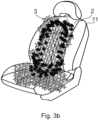
- FIG 3b schematically shows a car seat 11 having the exemplary smart cover 1.
- the smart cover comprises the sensor matrix as is shown in Figure 3a .
- the sensors are each shown in a cross shape but they can have any other shape.
- the smart cover is part of the car seat as its sheet 2 is sewn to other cuttings to form the seat cover.
- Some of the capacitive sensor elements are shown in red/dark while others are shown in a lighter colour. Signals of the capacitive sensor elements shown in red/dark can be read and interpreted to provide anthropometric data, occupant presence information and the position of the occupant on the seat.
- Figure 4 shows how an exemplary control unit processes signals/data and how it may cooperate with an exemplary sensor matrix and an exemplary physiology sensor unit, as a block diagram.
- individual sensors can be switched and may be adapted to their respective purpose (S11).
- Signals from the sensor matrix can be received by an acquisition unit (S12) which passes on acquired signals to a communication interface.
- the acquired signals may be converted into digital signals and/or can be filtered into processed signals (S12).
- the sensor unit's communication interface serves to transfer the signals/data to the control unit (S13).
- the sensor unit can have a receiver and a transmitter for communicating with the control unit.
- the exemplary control unit is arranged to determine minimum and maximum extreme points (S 14). These extreme points can be used for contour identification (S 15), anthropometric data estimation (S 16) and physiological signal sensing area estimation (S17). Based on the physiological signal sensing area estimation, sensor activation can be decided and sensor configuration can be instructed by the control unit (S 18). The control unit can communicate the instructions to the exemplary physiology sensor unit (S 19).
- sensors are activated by the exemplary physiology sensor unit (S20). Afterwards, signal acquisition occurs by the activated sensors (S21). The accuracy and characteristics of the acquired data can be verified by the exemplary physiology sensor unit (evaluation) (S22). The evaluation can be fed to a sensor matrix control unit and/or to the exemplary control unit (S23). The feedback can be used in the control unit for decisions on sensor activation and instructions for sensor configuration.
Landscapes
- Health & Medical Sciences (AREA)
- Life Sciences & Earth Sciences (AREA)
- Surgery (AREA)
- Animal Behavior & Ethology (AREA)
- Pathology (AREA)
- Engineering & Computer Science (AREA)
- Biomedical Technology (AREA)
- Heart & Thoracic Surgery (AREA)
- Medical Informatics (AREA)
- Molecular Biology (AREA)
- Physics & Mathematics (AREA)
- Biophysics (AREA)
- General Health & Medical Sciences (AREA)
- Public Health (AREA)
- Veterinary Medicine (AREA)
- Cardiology (AREA)
- Physiology (AREA)
- Vascular Medicine (AREA)
- Measuring Pulse, Heart Rate, Blood Pressure Or Blood Flow (AREA)
- Measuring And Recording Apparatus For Diagnosis (AREA)
Claims (11)
- Housse intelligente (1) pour détecter un signal, la housse intelligente comprenant
une feuille de préférence conductrice (2) de tissu ou de cuir conçue pour recouvrir un siège, un guidon et/ou un dispositif de direction en particulier d'un véhicule, et une matrice (3) de capteurs imprimée sur la feuille et comprenant plusieurs éléments capteurs (4), chacun des éléments capteurs étant conçu pour capter ou détecter un signal électrique émis par un corps d'un occupant humain, un contour du corps, et une dimension corporelle, la matrice (3) de capteurs étant conçue pour détecter le physique de l'occupant et étant conçue pour fournir des données anthropomorphiques (21) sur la base de signaux reçus par les éléments capteurs (4) [Revendication 3 à l'origine], moyennant quoi une unité de commande électronique est conçue pour traiter des signaux provenant des éléments capteurs (4) pour produire des données anthropométriques (21), un paramètre physiologique (22) et une ECG, une GSR ou une EEG (24) (paramètre physiologique évalué) de l'occupant [Revendication 7 à l'origine]. - Housse intelligente (1) selon la revendication 1, caractérisée en ce que la matrice de capteurs est constituée d'éléments capteurs capacitifs (4).
- Housse intelligente (1) selon l'une des revendications précédentes, caractérisée en ce qu'un premier groupe d'éléments capteurs est positionné et est activable pour détecter des signaux électriques cardiaques de l'occupant.
- Housse intelligente (1) selon l'une des revendications précédentes, caractérisée en ce que la feuille (2) est conçue pour recouvrir le guidon ou le dispositif de direction, et en ce que certains des éléments capteurs (4) sont positionnés et conçus pour détecter ou fournir une ECG à deux électrodes à partir des doigts de l'occupant placés sur le guidon ou le dispositif de direction, en particulier à partir des doigts de la main droite et de la main gauche placées sur le guidon ou le dispositif de direction.
- Housse intelligente (1) selon l'une des revendications 2 à 4, caractérisée en ce que la feuille est conçue pour recouvrir le siège, et en ce que certains des éléments capteurs (4) sont positionnés et conçus pour détecter ou fournir une ECG à 12 électrodes en estimant l'emplacement de positions exactes des électrodes à partir du profil généré électriquement ou des données anthropométriques.
- Véhicule équipé d'une housse intelligente (1) selon l'une des revendications précédentes et d'un système de sécurité, caractérisé en ce que la housse intelligente (1) est connectée au système de sécurité pour fournir des données anthropométriques (21) et un paramètre physiologique (22) de l'occupant au système de sécurité, de préférence caractérisé en ce que le système de sécurité est conçu pour fonctionner sur la base des données anthropométriques et du paramètre physiologique.
- Système caractérisé par une housse intelligente selon l'une des revendications 1 à 5 et un appareil de salle de sport équipé d'un siège et/ou d'un guidon, la housse intelligente (1) étant conçue pour recouvrir le siège ou le guidon.
- Procédé pour faire fonctionner une housse intelligente (1), en particulier selon l'une des revendications précédentes, le procédé comprenant les étapes suivantes :S2 captage ou détection par des éléments capteurs (4) d'un signal électrique émis par un corps d'un occupant humain, d'un contour du corps, et d'une dimension corporelle, les éléments capteurs (4) étant agencés dans une matrice (3) de capteurs de la housse intelligente (1), laquelle matrice de capteurs est imprimée sur une feuille de préférence conductrice (2) de tissu ou de cuir, la feuille étant conçue pour recouvrir un siège, un guidon ou un dispositif de direction en particulier d'un véhicule, en particulier pour détecter la présence de l'occupant et/ou pour fournir des informations (21) sur la présence de l'occupant, comprenant en outreS3 estimation du physique de l'occupant sur la base des signaux reçus par les éléments capteurs (4), et fourniture de données anthropométriques (21) respectives, etS5 accroissement de la sensibilité d'au moins un des éléments capteurs selon les données de l'étape S3, [Revendication 13 à l'origine] etS6' obtention d'un paramètre physiologique de l'occupant, à savoir d'une ECG, d'une GSR ou d'une EEG, sur la base des signaux reçus par les éléments capteurs, à l'aide de l'au moins un élément capteur de l'étape S5 [Revendication 13 à l'origine].
- Procédé selon la revendication 8, caractérisé par l'étape suivante
S1 activation de la housse intelligente (1), en particulier lors de la mise sous tension d'un dispositif d'allumage d'un véhicule. - Procédé selon l'une des revendications 8 et 9, caractérisé par l'étape suivante
S4 activation ou réglage d'un système de sécurité passif adaptatif d'un véhicule sur la base des données anthropomorphiques de l'étape S3. - Procédé selon l'une des revendications 8 à 10, caractérisé par l'étape suivante
S7 activation d'un système de sécurité prédictif et/ou d'un système de confort sur la base du paramètre physiologique de l'étape S6 ou de l'étape S6'.
Priority Applications (2)
| Application Number | Priority Date | Filing Date | Title |
|---|---|---|---|
| EP20167546.9A EP3888538B1 (fr) | 2020-04-01 | 2020-04-01 | Couvercle intelligent pour la détection d'un signal et procédé de fonctionnement du couvercle intelligent |
| PT201675469T PT3888538T (pt) | 2020-04-01 | 2020-04-01 | Cobertura inteligente para detetar um sinal e método para operar a cobertura inteligente |
Applications Claiming Priority (1)
| Application Number | Priority Date | Filing Date | Title |
|---|---|---|---|
| EP20167546.9A EP3888538B1 (fr) | 2020-04-01 | 2020-04-01 | Couvercle intelligent pour la détection d'un signal et procédé de fonctionnement du couvercle intelligent |
Publications (2)
| Publication Number | Publication Date |
|---|---|
| EP3888538A1 EP3888538A1 (fr) | 2021-10-06 |
| EP3888538B1 true EP3888538B1 (fr) | 2024-06-05 |
Family
ID=70154292
Family Applications (1)
| Application Number | Title | Priority Date | Filing Date |
|---|---|---|---|
| EP20167546.9A Active EP3888538B1 (fr) | 2020-04-01 | 2020-04-01 | Couvercle intelligent pour la détection d'un signal et procédé de fonctionnement du couvercle intelligent |
Country Status (2)
| Country | Link |
|---|---|
| EP (1) | EP3888538B1 (fr) |
| PT (1) | PT3888538T (fr) |
Family Cites Families (6)
| Publication number | Priority date | Publication date | Assignee | Title |
|---|---|---|---|---|
| US7629890B2 (en) * | 2003-12-04 | 2009-12-08 | Hoana Medical, Inc. | System and methods for intelligent medical vigilance with bed exit detection |
| PT106102B (pt) * | 2012-01-19 | 2014-08-11 | Inst Superior Tecnico | Dispositivo e método para reconhecimento biométrico contínuo baseado em sinais eletrocardiográficos |
| US9975452B2 (en) * | 2013-09-05 | 2018-05-22 | Ts Tech Co., Ltd. | Seat having capacitive coupling sensor |
| ES2485617B1 (es) * | 2013-09-16 | 2015-04-06 | Sensing Tex, S.L. | Sensor textil piezo-resistivo y sistema de detección del ritmo cardiaco y/o respiratorio |
| US10299520B1 (en) * | 2014-08-12 | 2019-05-28 | Apple Inc. | Fabric-based items with environmental control elements |
| US11241934B2 (en) * | 2018-12-28 | 2022-02-08 | Intel Corporation | Techniques to optimize vehicular systems for occupant presence and condition |
-
2020
- 2020-04-01 EP EP20167546.9A patent/EP3888538B1/fr active Active
- 2020-04-01 PT PT201675469T patent/PT3888538T/pt unknown
Also Published As
| Publication number | Publication date |
|---|---|
| PT3888538T (pt) | 2024-07-04 |
| EP3888538A1 (fr) | 2021-10-06 |
Similar Documents
| Publication | Publication Date | Title |
|---|---|---|
| US20220257169A1 (en) | Neuorological condition detection unit and method of using the same | |
| JP6461480B2 (ja) | 車両内でのバイオメトリック識別を実行するシステム及び方法 | |
| US8847769B2 (en) | Signal detecting device for detecting a difference signal for an electrical measurement of a vital parameter of a living being | |
| EP3107455B1 (fr) | Siège de véhicule comprenant des capteurs intégrés | |
| US20090281394A1 (en) | Bio-mechanical sensor system | |
| US10845802B2 (en) | Method for operating a motor vehicle | |
| WO2014085302A1 (fr) | Siège de véhicule ayant des capteurs intégrés | |
| Said et al. | Wearable bio-sensors bracelet for driveras health emergency detection | |
| JP2009107582A (ja) | 車輌装備品 | |
| CN107212861A (zh) | 应用于车辆的生理特征检测系统及方法 | |
| EP4064979B1 (fr) | Procédé de détermination d'une mesure de capteur fusionnée et système de sécurité de véhicule utilisant la mesure de capteur fusionnée | |
| CN217525136U (zh) | 一种具有生理参数监测功能的驾驶舱 | |
| EP3888538B1 (fr) | Couvercle intelligent pour la détection d'un signal et procédé de fonctionnement du couvercle intelligent | |
| EP3880513B1 (fr) | Housse intelligente pour siège de véhicule et siège de véhicule comprenant ladite housse intelligente | |
| Yang et al. | Vehicle driver's ECG and sitting posture monitoring system | |
| EP3015055A1 (fr) | Système de monitoring d'un conducteur | |
| US20210015382A1 (en) | Heart Beat Monitoring Device | |
| WO2017215879A1 (fr) | Article vestimentaire à dispositif de détection intégré, procédé d'utilisation dudit article vestimentaire dans plusieurs véhicules à moteur, système comprenant un véhicule à moteur et un article vestimentaire | |
| JPH04183439A (ja) | 運転者の居眠り検出装置 | |
| JP2021516598A (ja) | テレメトリー一体化システム | |
| Cheng et al. | A vital wearing system with wireless capability | |
| KR102944206B1 (ko) | 통합 생체 모니터링 시스템 및 이를 지원하는 서버 장치 | |
| CN120167966A (zh) | 一种用于驾驶员疲劳检测的压力传感坐垫及其检测方法 | |
| US20250268519A1 (en) | Device and method for measurement of physiological parameters by temporary contact with a receptor surface | |
| CN213852759U (zh) | 一种颈部按摩仪 |
Legal Events
| Date | Code | Title | Description |
|---|---|---|---|
| PUAI | Public reference made under article 153(3) epc to a published international application that has entered the european phase |
Free format text: ORIGINAL CODE: 0009012 |
|
| STAA | Information on the status of an ep patent application or granted ep patent |
Free format text: STATUS: THE APPLICATION HAS BEEN PUBLISHED |
|
| AK | Designated contracting states |
Kind code of ref document: A1 Designated state(s): AL AT BE BG CH CY CZ DE DK EE ES FI FR GB GR HR HU IE IS IT LI LT LU LV MC MK MT NL NO PL PT RO RS SE SI SK SM TR |
|
| STAA | Information on the status of an ep patent application or granted ep patent |
Free format text: STATUS: REQUEST FOR EXAMINATION WAS MADE |
|
| 17P | Request for examination filed |
Effective date: 20220406 |
|
| RBV | Designated contracting states (corrected) |
Designated state(s): AL AT BE BG CH CY CZ DE DK EE ES FI FR GB GR HR HU IE IS IT LI LT LU LV MC MK MT NL NO PL PT RO RS SE SI SK SM TR |
|
| GRAP | Despatch of communication of intention to grant a patent |
Free format text: ORIGINAL CODE: EPIDOSNIGR1 |
|
| STAA | Information on the status of an ep patent application or granted ep patent |
Free format text: STATUS: GRANT OF PATENT IS INTENDED |
|
| RIC1 | Information provided on ipc code assigned before grant |
Ipc: A61B 5/00 20060101ALI20231215BHEP Ipc: A61B 5/024 20060101ALI20231215BHEP Ipc: A61B 5/021 20060101AFI20231215BHEP |
|
| INTG | Intention to grant announced |
Effective date: 20240118 |
|
| P01 | Opt-out of the competence of the unified patent court (upc) registered |
Effective date: 20240301 |
|
| GRAS | Grant fee paid |
Free format text: ORIGINAL CODE: EPIDOSNIGR3 |
|
| GRAA | (expected) grant |
Free format text: ORIGINAL CODE: 0009210 |
|
| STAA | Information on the status of an ep patent application or granted ep patent |
Free format text: STATUS: THE PATENT HAS BEEN GRANTED |
|
| AK | Designated contracting states |
Kind code of ref document: B1 Designated state(s): AL AT BE BG CH CY CZ DE DK EE ES FI FR GB GR HR HU IE IS IT LI LT LU LV MC MK MT NL NO PL PT RO RS SE SI SK SM TR |
|
| REG | Reference to a national code |
Ref country code: CH Ref legal event code: EP |
|
| REG | Reference to a national code |
Ref country code: DE Ref legal event code: R096 Ref document number: 602020031863 Country of ref document: DE |
|
| REG | Reference to a national code |
Ref country code: IE Ref legal event code: FG4D |
|
| REG | Reference to a national code |
Ref country code: PT Ref legal event code: SC4A Ref document number: 3888538 Country of ref document: PT Date of ref document: 20240704 Kind code of ref document: T Free format text: AVAILABILITY OF NATIONAL TRANSLATION Effective date: 20240627 |
|
| REG | Reference to a national code |
Ref country code: LT Ref legal event code: MG9D |
|
| PG25 | Lapsed in a contracting state [announced via postgrant information from national office to epo] |
Ref country code: BG Free format text: LAPSE BECAUSE OF FAILURE TO SUBMIT A TRANSLATION OF THE DESCRIPTION OR TO PAY THE FEE WITHIN THE PRESCRIBED TIME-LIMIT Effective date: 20240605 |
|
| REG | Reference to a national code |
Ref country code: NL Ref legal event code: MP Effective date: 20240605 |
|
| PG25 | Lapsed in a contracting state [announced via postgrant information from national office to epo] |
Ref country code: FI Free format text: LAPSE BECAUSE OF FAILURE TO SUBMIT A TRANSLATION OF THE DESCRIPTION OR TO PAY THE FEE WITHIN THE PRESCRIBED TIME-LIMIT Effective date: 20240605 Ref country code: HR Free format text: LAPSE BECAUSE OF FAILURE TO SUBMIT A TRANSLATION OF THE DESCRIPTION OR TO PAY THE FEE WITHIN THE PRESCRIBED TIME-LIMIT Effective date: 20240605 |
|
| PG25 | Lapsed in a contracting state [announced via postgrant information from national office to epo] |
Ref country code: GR Free format text: LAPSE BECAUSE OF FAILURE TO SUBMIT A TRANSLATION OF THE DESCRIPTION OR TO PAY THE FEE WITHIN THE PRESCRIBED TIME-LIMIT Effective date: 20240906 |
|
| PG25 | Lapsed in a contracting state [announced via postgrant information from national office to epo] |
Ref country code: ES Free format text: LAPSE BECAUSE OF FAILURE TO SUBMIT A TRANSLATION OF THE DESCRIPTION OR TO PAY THE FEE WITHIN THE PRESCRIBED TIME-LIMIT Effective date: 20240605 |
|
| PG25 | Lapsed in a contracting state [announced via postgrant information from national office to epo] |
Ref country code: LV Free format text: LAPSE BECAUSE OF FAILURE TO SUBMIT A TRANSLATION OF THE DESCRIPTION OR TO PAY THE FEE WITHIN THE PRESCRIBED TIME-LIMIT Effective date: 20240605 |
|
| PG25 | Lapsed in a contracting state [announced via postgrant information from national office to epo] |
Ref country code: NO Free format text: LAPSE BECAUSE OF FAILURE TO SUBMIT A TRANSLATION OF THE DESCRIPTION OR TO PAY THE FEE WITHIN THE PRESCRIBED TIME-LIMIT Effective date: 20240905 Ref country code: LV Free format text: LAPSE BECAUSE OF FAILURE TO SUBMIT A TRANSLATION OF THE DESCRIPTION OR TO PAY THE FEE WITHIN THE PRESCRIBED TIME-LIMIT Effective date: 20240605 Ref country code: HR Free format text: LAPSE BECAUSE OF FAILURE TO SUBMIT A TRANSLATION OF THE DESCRIPTION OR TO PAY THE FEE WITHIN THE PRESCRIBED TIME-LIMIT Effective date: 20240605 Ref country code: GR Free format text: LAPSE BECAUSE OF FAILURE TO SUBMIT A TRANSLATION OF THE DESCRIPTION OR TO PAY THE FEE WITHIN THE PRESCRIBED TIME-LIMIT Effective date: 20240906 Ref country code: FI Free format text: LAPSE BECAUSE OF FAILURE TO SUBMIT A TRANSLATION OF THE DESCRIPTION OR TO PAY THE FEE WITHIN THE PRESCRIBED TIME-LIMIT Effective date: 20240605 Ref country code: ES Free format text: LAPSE BECAUSE OF FAILURE TO SUBMIT A TRANSLATION OF THE DESCRIPTION OR TO PAY THE FEE WITHIN THE PRESCRIBED TIME-LIMIT Effective date: 20240605 Ref country code: BG Free format text: LAPSE BECAUSE OF FAILURE TO SUBMIT A TRANSLATION OF THE DESCRIPTION OR TO PAY THE FEE WITHIN THE PRESCRIBED TIME-LIMIT Effective date: 20240605 Ref country code: RS Free format text: LAPSE BECAUSE OF FAILURE TO SUBMIT A TRANSLATION OF THE DESCRIPTION OR TO PAY THE FEE WITHIN THE PRESCRIBED TIME-LIMIT Effective date: 20240905 |
|
| PG25 | Lapsed in a contracting state [announced via postgrant information from national office to epo] |
Ref country code: NL Free format text: LAPSE BECAUSE OF FAILURE TO SUBMIT A TRANSLATION OF THE DESCRIPTION OR TO PAY THE FEE WITHIN THE PRESCRIBED TIME-LIMIT Effective date: 20240605 |
|
| REG | Reference to a national code |
Ref country code: AT Ref legal event code: MK05 Ref document number: 1691815 Country of ref document: AT Kind code of ref document: T Effective date: 20240605 |
|
| PG25 | Lapsed in a contracting state [announced via postgrant information from national office to epo] |
Ref country code: NL Free format text: LAPSE BECAUSE OF FAILURE TO SUBMIT A TRANSLATION OF THE DESCRIPTION OR TO PAY THE FEE WITHIN THE PRESCRIBED TIME-LIMIT Effective date: 20240605 |
|
| PG25 | Lapsed in a contracting state [announced via postgrant information from national office to epo] |
Ref country code: PL Free format text: LAPSE BECAUSE OF FAILURE TO SUBMIT A TRANSLATION OF THE DESCRIPTION OR TO PAY THE FEE WITHIN THE PRESCRIBED TIME-LIMIT Effective date: 20240605 |
|
| PG25 | Lapsed in a contracting state [announced via postgrant information from national office to epo] |
Ref country code: EE Free format text: LAPSE BECAUSE OF FAILURE TO SUBMIT A TRANSLATION OF THE DESCRIPTION OR TO PAY THE FEE WITHIN THE PRESCRIBED TIME-LIMIT Effective date: 20240605 |
|
| PG25 | Lapsed in a contracting state [announced via postgrant information from national office to epo] |
Ref country code: AT Free format text: LAPSE BECAUSE OF FAILURE TO SUBMIT A TRANSLATION OF THE DESCRIPTION OR TO PAY THE FEE WITHIN THE PRESCRIBED TIME-LIMIT Effective date: 20240605 Ref country code: IS Free format text: LAPSE BECAUSE OF FAILURE TO SUBMIT A TRANSLATION OF THE DESCRIPTION OR TO PAY THE FEE WITHIN THE PRESCRIBED TIME-LIMIT Effective date: 20241005 |
|
| PG25 | Lapsed in a contracting state [announced via postgrant information from national office to epo] |
Ref country code: CZ Free format text: LAPSE BECAUSE OF FAILURE TO SUBMIT A TRANSLATION OF THE DESCRIPTION OR TO PAY THE FEE WITHIN THE PRESCRIBED TIME-LIMIT Effective date: 20240605 |
|
| PG25 | Lapsed in a contracting state [announced via postgrant information from national office to epo] |
Ref country code: RO Free format text: LAPSE BECAUSE OF FAILURE TO SUBMIT A TRANSLATION OF THE DESCRIPTION OR TO PAY THE FEE WITHIN THE PRESCRIBED TIME-LIMIT Effective date: 20240605 Ref country code: SK Free format text: LAPSE BECAUSE OF FAILURE TO SUBMIT A TRANSLATION OF THE DESCRIPTION OR TO PAY THE FEE WITHIN THE PRESCRIBED TIME-LIMIT Effective date: 20240605 |
|
| PG25 | Lapsed in a contracting state [announced via postgrant information from national office to epo] |
Ref country code: SM Free format text: LAPSE BECAUSE OF FAILURE TO SUBMIT A TRANSLATION OF THE DESCRIPTION OR TO PAY THE FEE WITHIN THE PRESCRIBED TIME-LIMIT Effective date: 20240605 |
|
| PG25 | Lapsed in a contracting state [announced via postgrant information from national office to epo] |
Ref country code: SM Free format text: LAPSE BECAUSE OF FAILURE TO SUBMIT A TRANSLATION OF THE DESCRIPTION OR TO PAY THE FEE WITHIN THE PRESCRIBED TIME-LIMIT Effective date: 20240605 Ref country code: SK Free format text: LAPSE BECAUSE OF FAILURE TO SUBMIT A TRANSLATION OF THE DESCRIPTION OR TO PAY THE FEE WITHIN THE PRESCRIBED TIME-LIMIT Effective date: 20240605 Ref country code: RO Free format text: LAPSE BECAUSE OF FAILURE TO SUBMIT A TRANSLATION OF THE DESCRIPTION OR TO PAY THE FEE WITHIN THE PRESCRIBED TIME-LIMIT Effective date: 20240605 Ref country code: PL Free format text: LAPSE BECAUSE OF FAILURE TO SUBMIT A TRANSLATION OF THE DESCRIPTION OR TO PAY THE FEE WITHIN THE PRESCRIBED TIME-LIMIT Effective date: 20240605 Ref country code: IS Free format text: LAPSE BECAUSE OF FAILURE TO SUBMIT A TRANSLATION OF THE DESCRIPTION OR TO PAY THE FEE WITHIN THE PRESCRIBED TIME-LIMIT Effective date: 20241005 Ref country code: EE Free format text: LAPSE BECAUSE OF FAILURE TO SUBMIT A TRANSLATION OF THE DESCRIPTION OR TO PAY THE FEE WITHIN THE PRESCRIBED TIME-LIMIT Effective date: 20240605 Ref country code: CZ Free format text: LAPSE BECAUSE OF FAILURE TO SUBMIT A TRANSLATION OF THE DESCRIPTION OR TO PAY THE FEE WITHIN THE PRESCRIBED TIME-LIMIT Effective date: 20240605 Ref country code: AT Free format text: LAPSE BECAUSE OF FAILURE TO SUBMIT A TRANSLATION OF THE DESCRIPTION OR TO PAY THE FEE WITHIN THE PRESCRIBED TIME-LIMIT Effective date: 20240605 |
|
| PG25 | Lapsed in a contracting state [announced via postgrant information from national office to epo] |
Ref country code: IT Free format text: LAPSE BECAUSE OF FAILURE TO SUBMIT A TRANSLATION OF THE DESCRIPTION OR TO PAY THE FEE WITHIN THE PRESCRIBED TIME-LIMIT Effective date: 20240605 |
|
| REG | Reference to a national code |
Ref country code: DE Ref legal event code: R097 Ref document number: 602020031863 Country of ref document: DE |
|
| PLBE | No opposition filed within time limit |
Free format text: ORIGINAL CODE: 0009261 |
|
| STAA | Information on the status of an ep patent application or granted ep patent |
Free format text: STATUS: NO OPPOSITION FILED WITHIN TIME LIMIT |
|
| PG25 | Lapsed in a contracting state [announced via postgrant information from national office to epo] |
Ref country code: DK Free format text: LAPSE BECAUSE OF FAILURE TO SUBMIT A TRANSLATION OF THE DESCRIPTION OR TO PAY THE FEE WITHIN THE PRESCRIBED TIME-LIMIT Effective date: 20240605 |
|
| 26N | No opposition filed |
Effective date: 20250306 |
|
| PGFP | Annual fee paid to national office [announced via postgrant information from national office to epo] |
Ref country code: DE Payment date: 20250430 Year of fee payment: 6 |
|
| PG25 | Lapsed in a contracting state [announced via postgrant information from national office to epo] |
Ref country code: SE Free format text: LAPSE BECAUSE OF FAILURE TO SUBMIT A TRANSLATION OF THE DESCRIPTION OR TO PAY THE FEE WITHIN THE PRESCRIBED TIME-LIMIT Effective date: 20240605 |
|
| REG | Reference to a national code |
Ref country code: CH Ref legal event code: H13 Free format text: ST27 STATUS EVENT CODE: U-0-0-H10-H13 (AS PROVIDED BY THE NATIONAL OFFICE) Effective date: 20251125 |
|
| PG25 | Lapsed in a contracting state [announced via postgrant information from national office to epo] |
Ref country code: LU Free format text: LAPSE BECAUSE OF NON-PAYMENT OF DUE FEES Effective date: 20250401 |
|
| PG25 | Lapsed in a contracting state [announced via postgrant information from national office to epo] |
Ref country code: MC Free format text: LAPSE BECAUSE OF FAILURE TO SUBMIT A TRANSLATION OF THE DESCRIPTION OR TO PAY THE FEE WITHIN THE PRESCRIBED TIME-LIMIT Effective date: 20240605 |
|
| GBPC | Gb: european patent ceased through non-payment of renewal fee |
Effective date: 20250401 |
|
| REG | Reference to a national code |
Ref country code: BE Ref legal event code: MM Effective date: 20250430 |
|
| PG25 | Lapsed in a contracting state [announced via postgrant information from national office to epo] |
Ref country code: GB Free format text: LAPSE BECAUSE OF NON-PAYMENT OF DUE FEES Effective date: 20250401 |
|
| PG25 | Lapsed in a contracting state [announced via postgrant information from national office to epo] |
Ref country code: FR Free format text: LAPSE BECAUSE OF NON-PAYMENT OF DUE FEES Effective date: 20250430 |
|
| PG25 | Lapsed in a contracting state [announced via postgrant information from national office to epo] |
Ref country code: BE Free format text: LAPSE BECAUSE OF NON-PAYMENT OF DUE FEES Effective date: 20250430 |
|
| PG25 | Lapsed in a contracting state [announced via postgrant information from national office to epo] |
Ref country code: CH Free format text: LAPSE BECAUSE OF NON-PAYMENT OF DUE FEES Effective date: 20250430 |
|
| PG25 | Lapsed in a contracting state [announced via postgrant information from national office to epo] |
Ref country code: IE Free format text: LAPSE BECAUSE OF NON-PAYMENT OF DUE FEES Effective date: 20250401 |
|
| PGFP | Annual fee paid to national office [announced via postgrant information from national office to epo] |
Ref country code: PT Payment date: 20260319 Year of fee payment: 7 |