EP3888824B1 - Appareil et procédé de fabrication - Google Patents
Appareil et procédé de fabrication Download PDFInfo
- Publication number
- EP3888824B1 EP3888824B1 EP21165948.7A EP21165948A EP3888824B1 EP 3888824 B1 EP3888824 B1 EP 3888824B1 EP 21165948 A EP21165948 A EP 21165948A EP 3888824 B1 EP3888824 B1 EP 3888824B1
- Authority
- EP
- European Patent Office
- Prior art keywords
- droplets
- discharge
- powder
- fabrication
- liquid
- Prior art date
- Legal status (The legal status is an assumption and is not a legal conclusion. Google has not performed a legal analysis and makes no representation as to the accuracy of the status listed.)
- Active
Links
Images



Classifications
-
- B—PERFORMING OPERATIONS; TRANSPORTING
- B22—CASTING; POWDER METALLURGY
- B22F—WORKING METALLIC POWDER; MANUFACTURE OF ARTICLES FROM METALLIC POWDER; MAKING METALLIC POWDER; APPARATUS OR DEVICES SPECIALLY ADAPTED FOR METALLIC POWDER
- B22F3/00—Manufacture of workpieces or articles from metallic powder characterised by the manner of compacting or sintering; Apparatus specially adapted therefor ; Presses and furnaces
- B22F3/003—Apparatus, e.g. furnaces
-
- B—PERFORMING OPERATIONS; TRANSPORTING
- B29—WORKING OF PLASTICS; WORKING OF SUBSTANCES IN A PLASTIC STATE IN GENERAL
- B29C—SHAPING OR JOINING OF PLASTICS; SHAPING OF MATERIAL IN A PLASTIC STATE, NOT OTHERWISE PROVIDED FOR; AFTER-TREATMENT OF THE SHAPED PRODUCTS, e.g. REPAIRING
- B29C64/00—Additive manufacturing, i.e. manufacturing of three-dimensional [3D] objects by additive deposition, additive agglomeration or additive layering, e.g. by 3D printing, stereolithography or selective laser sintering
- B29C64/10—Processes of additive manufacturing
- B29C64/165—Processes of additive manufacturing using a combination of solid and fluid materials, e.g. a powder selectively bound by a liquid binder, catalyst, inhibitor or energy absorber
-
- B—PERFORMING OPERATIONS; TRANSPORTING
- B22—CASTING; POWDER METALLURGY
- B22F—WORKING METALLIC POWDER; MANUFACTURE OF ARTICLES FROM METALLIC POWDER; MAKING METALLIC POWDER; APPARATUS OR DEVICES SPECIALLY ADAPTED FOR METALLIC POWDER
- B22F10/00—Additive manufacturing of workpieces or articles from metallic powder
- B22F10/10—Formation of a green body
- B22F10/14—Formation of a green body by jetting of binder onto a bed of metal powder
-
- B—PERFORMING OPERATIONS; TRANSPORTING
- B22—CASTING; POWDER METALLURGY
- B22F—WORKING METALLIC POWDER; MANUFACTURE OF ARTICLES FROM METALLIC POWDER; MAKING METALLIC POWDER; APPARATUS OR DEVICES SPECIALLY ADAPTED FOR METALLIC POWDER
- B22F10/00—Additive manufacturing of workpieces or articles from metallic powder
- B22F10/30—Process control
-
- B—PERFORMING OPERATIONS; TRANSPORTING
- B22—CASTING; POWDER METALLURGY
- B22F—WORKING METALLIC POWDER; MANUFACTURE OF ARTICLES FROM METALLIC POWDER; MAKING METALLIC POWDER; APPARATUS OR DEVICES SPECIALLY ADAPTED FOR METALLIC POWDER
- B22F10/00—Additive manufacturing of workpieces or articles from metallic powder
- B22F10/30—Process control
- B22F10/38—Process control to achieve specific product aspects, e.g. surface smoothness, density, porosity or hollow structures
-
- B—PERFORMING OPERATIONS; TRANSPORTING
- B29—WORKING OF PLASTICS; WORKING OF SUBSTANCES IN A PLASTIC STATE IN GENERAL
- B29C—SHAPING OR JOINING OF PLASTICS; SHAPING OF MATERIAL IN A PLASTIC STATE, NOT OTHERWISE PROVIDED FOR; AFTER-TREATMENT OF THE SHAPED PRODUCTS, e.g. REPAIRING
- B29C64/00—Additive manufacturing, i.e. manufacturing of three-dimensional [3D] objects by additive deposition, additive agglomeration or additive layering, e.g. by 3D printing, stereolithography or selective laser sintering
- B29C64/20—Apparatus for additive manufacturing; Details thereof or accessories therefor
- B29C64/205—Means for applying layers
- B29C64/209—Heads; Nozzles
-
- B—PERFORMING OPERATIONS; TRANSPORTING
- B29—WORKING OF PLASTICS; WORKING OF SUBSTANCES IN A PLASTIC STATE IN GENERAL
- B29C—SHAPING OR JOINING OF PLASTICS; SHAPING OF MATERIAL IN A PLASTIC STATE, NOT OTHERWISE PROVIDED FOR; AFTER-TREATMENT OF THE SHAPED PRODUCTS, e.g. REPAIRING
- B29C64/00—Additive manufacturing, i.e. manufacturing of three-dimensional [3D] objects by additive deposition, additive agglomeration or additive layering, e.g. by 3D printing, stereolithography or selective laser sintering
- B29C64/30—Auxiliary operations or equipment
- B29C64/307—Handling of material to be used in additive manufacturing
- B29C64/321—Feeding
-
- B—PERFORMING OPERATIONS; TRANSPORTING
- B29—WORKING OF PLASTICS; WORKING OF SUBSTANCES IN A PLASTIC STATE IN GENERAL
- B29C—SHAPING OR JOINING OF PLASTICS; SHAPING OF MATERIAL IN A PLASTIC STATE, NOT OTHERWISE PROVIDED FOR; AFTER-TREATMENT OF THE SHAPED PRODUCTS, e.g. REPAIRING
- B29C64/00—Additive manufacturing, i.e. manufacturing of three-dimensional [3D] objects by additive deposition, additive agglomeration or additive layering, e.g. by 3D printing, stereolithography or selective laser sintering
- B29C64/30—Auxiliary operations or equipment
- B29C64/386—Data acquisition or data processing for additive manufacturing
- B29C64/393—Data acquisition or data processing for additive manufacturing for controlling or regulating additive manufacturing processes
-
- B—PERFORMING OPERATIONS; TRANSPORTING
- B33—ADDITIVE MANUFACTURING TECHNOLOGY
- B33Y—ADDITIVE MANUFACTURING, i.e. MANUFACTURING OF THREE-DIMENSIONAL [3D] OBJECTS BY ADDITIVE DEPOSITION, ADDITIVE AGGLOMERATION OR ADDITIVE LAYERING, e.g. BY 3D PRINTING, STEREOLITHOGRAPHY OR SELECTIVE LASER SINTERING
- B33Y10/00—Processes of additive manufacturing
-
- B—PERFORMING OPERATIONS; TRANSPORTING
- B33—ADDITIVE MANUFACTURING TECHNOLOGY
- B33Y—ADDITIVE MANUFACTURING, i.e. MANUFACTURING OF THREE-DIMENSIONAL [3D] OBJECTS BY ADDITIVE DEPOSITION, ADDITIVE AGGLOMERATION OR ADDITIVE LAYERING, e.g. BY 3D PRINTING, STEREOLITHOGRAPHY OR SELECTIVE LASER SINTERING
- B33Y30/00—Apparatus for additive manufacturing; Details thereof or accessories therefor
-
- B—PERFORMING OPERATIONS; TRANSPORTING
- B33—ADDITIVE MANUFACTURING TECHNOLOGY
- B33Y—ADDITIVE MANUFACTURING, i.e. MANUFACTURING OF THREE-DIMENSIONAL [3D] OBJECTS BY ADDITIVE DEPOSITION, ADDITIVE AGGLOMERATION OR ADDITIVE LAYERING, e.g. BY 3D PRINTING, STEREOLITHOGRAPHY OR SELECTIVE LASER SINTERING
- B33Y40/00—Auxiliary operations or equipment, e.g. for material handling
-
- B—PERFORMING OPERATIONS; TRANSPORTING
- B33—ADDITIVE MANUFACTURING TECHNOLOGY
- B33Y—ADDITIVE MANUFACTURING, i.e. MANUFACTURING OF THREE-DIMENSIONAL [3D] OBJECTS BY ADDITIVE DEPOSITION, ADDITIVE AGGLOMERATION OR ADDITIVE LAYERING, e.g. BY 3D PRINTING, STEREOLITHOGRAPHY OR SELECTIVE LASER SINTERING
- B33Y50/00—Data acquisition or data processing for additive manufacturing
- B33Y50/02—Data acquisition or data processing for additive manufacturing for controlling or regulating additive manufacturing processes
-
- B—PERFORMING OPERATIONS; TRANSPORTING
- B22—CASTING; POWDER METALLURGY
- B22F—WORKING METALLIC POWDER; MANUFACTURE OF ARTICLES FROM METALLIC POWDER; MAKING METALLIC POWDER; APPARATUS OR DEVICES SPECIALLY ADAPTED FOR METALLIC POWDER
- B22F2999/00—Aspects linked to processes or compositions used in powder metallurgy
-
- Y—GENERAL TAGGING OF NEW TECHNOLOGICAL DEVELOPMENTS; GENERAL TAGGING OF CROSS-SECTIONAL TECHNOLOGIES SPANNING OVER SEVERAL SECTIONS OF THE IPC; TECHNICAL SUBJECTS COVERED BY FORMER USPC CROSS-REFERENCE ART COLLECTIONS [XRACs] AND DIGESTS
- Y02—TECHNOLOGIES OR APPLICATIONS FOR MITIGATION OR ADAPTATION AGAINST CLIMATE CHANGE
- Y02P—CLIMATE CHANGE MITIGATION TECHNOLOGIES IN THE PRODUCTION OR PROCESSING OF GOODS
- Y02P10/00—Technologies related to metal processing
- Y02P10/25—Process efficiency
Definitions
- Embodiments of the present disclosure relate to a fabricating apparatus and a fabricating method according to the preamble of respective claims 1 and 6.
- a lamination fabrication method of laminating for example, resin or metal based on cross-sectional data of a three-dimensional object to fabricate the three-dimensional object.
- a powder lamination fabrication method is known as one example of the lamination fabrication method.
- a powder bed fusion method, a binder jetting method, and the like are also known as examples of the powder lamination fabrication methods.
- the powder bed fusion method is a method in which laminated metal powder is irradiated with laser light and sintered to form a fabricated object.
- a fabrication liquid jetting method is a method in which fabrication liquid is discharged onto laminated powder and solidified to form a fabricated object.
- US 2009/020920 A1 discloses a fabricating apparatus according to the initially mentioned type.
- the present disclosure has been made in view of the above-described disadvantages, and an object of the present disclosure is to provide a fabricating apparatus and a fabricating method capable of reducing stirring up of powder when droplets of fabrication liquid land on a powder surface and preventing a low density of a fabricated object or the like.
- stirring up of powder when droplets of fabrication liquid land on a powder surface can be reduced and a low density of a fabricated object with a low density or the like.
- FIG. 1 is a top view of a three-dimensional fabricating apparatus (an example of a fabricating apparatus) according to an embodiment of the present disclosure.
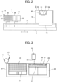
- FIG. 2 is a side view of the three-dimensional fabricating apparatus illustrated with a part of the three-dimensional fabricating apparatus cut away according to an embodiment of the present disclosure.
- FIG. 3 is a cross-sectional view of a powder chamber of the three-dimensional fabricating apparatus according to an embodiment of the present disclosure.
- FIG. 4 is a perspective view of a main part of the three-dimensional fabricating apparatus according to an embodiment of the present disclosure.
- FIG. 5 is a perspective view of the powder chamber and a perspective view of a liquid discharge unit of the three-dimensional fabricating apparatus according to an embodiment of the present disclosure.
- a three-dimensional fabricating apparatus 601 (also referred to as a powder fabricating apparatus or a powder-particle fabricating apparatus) according to embodiments of the present disclosure includes a fabricating device 1 and a fabricating unit 5.
- the fabricating device 1 forms a fabrication layer 30, which is a layered three-dimensional object formed by binding powder (powder particles).
- the fabricating unit 5 discharges a fabrication liquid 10 to a powder layer 31 spread in a layered manner in the fabricating device 1 to fabricate a three-dimensional object.
- the fabricating device 1 is an example of a powder layer forming device and includes a powder chamber 11 and a flattening roller 12 as a rotator which is a flattening member (recoater).
- the flattening member may be, for example, a plate (blade) in place of a rotator.
- the powder chamber 11 includes a supply chamber 21 to supply powder 20 and a fabrication chamber 22 in which the fabrication layer 30 is laminated to fabricate a three-dimensional object.
- a bottom of the supply chamber 21 is movable in a vertical direction (height direction) as a supply stage 23.
- a bottom of the fabrication chamber 22 is movable in the vertical direction (height direction) as a fabrication stage 24.
- a three-dimensional object in which the fabrication layer 30 is laminated is fabricated on the fabrication stage 24.
- the supply stage 23 is moved up and down in directions indicated by arrow Z (height direction) by a motor 27.
- the fabrication stage 24 is moved up and down in the directions indicated by arrow Z by a motor 28.
- Z directions simply referred to as "Z directions”.
- the powder chamber 11 has a box shape, and includes two chambers, i.e., the supply chamber 21 and the fabrication chamber 22, each having an open upper surface.
- the supply stage 23 is disposed inside the supply chamber 21 so as to be raised and lowered.
- the fabrication stage 24 is disposed inside the fabrication chamber 22 so as to be raised and lowered.
- a surplus powder receiving chamber 29 including the peripheries of the supply chamber 21 and the fabrication chamber 22 is provided adjacent to the fabrication chamber 22.
- the powder 20 is transferred by the flattening roller 12 when the powder layer 31 is formed, and a surplus of the powder 20 falls into the surplus powder receiving chamber 29.
- a powder supply device 554 (see FIG. 6 ) is provided above the supply chamber 21, and the surplus powder 20 that has fallen into the surplus powder receiving chamber 29 is returned to the supply chamber 21 by the powder supply device 554.
- the flattening roller 12 supplies the powder 20 supplied onto the supply stage 23 of the supply chamber 21 to the fabrication chamber 22 and flattens the powder 20 to form the powder layer 31.
- the flattening roller 12 is moved by a reciprocating mechanism 25 so as to reciprocate (in directions indicated by arrow Y (hereinafter, Y directions) illustrated in FIGS. 2 and 4 relative to a stage surface (surface on which the powder 20 is placed) of the fabrication stage 24.
- the flattening roller 12 is rotationally driven by a motor 26.
- the flattening roller 12 transfers and supplies the powder 20 from the supply chamber 21 to the fabrication chamber 22, and flattens the surface of the powder 20 to form the powder layer 31 which is a layered powder having a predetermined thickness.
- the flattening roller 12 is a rod-shaped member longer than the inner dimension of each of the fabrication chamber 22 and the supply chamber 21 (the width of a portion to which the powder is supplied or charged), and is reciprocated in the Y directions (in other words, along a sub-scanning direction) along the stage surface of the fabrication stage 24 by the reciprocating mechanism 25.
- the flattening roller 12 is rotationally driven by the motor 26 illustrated in FIG. 4 to horizontally move to pass above the supply chamber 21 and the fabrication chamber 22 from the outside of the supply chamber 21.
- the powder 20 is transferred and supplied onto the fabrication chamber 22, and the flattening roller 12 flattens the powder 20 while passing over the fabrication chamber 22 to form the powder layer 31.
- the three-dimensional fabricating apparatus 601 is described on the assumption that the powder chamber 11 of the fabricating device 1 includes the two chambers, i.e., the supply chamber 21 and the fabrication chamber 22. However, only the fabrication chamber 22 may be provided and the powder 20 may be supplied from a powder supply device to the fabrication chamber 22 and flattened by the flattening roller 12.
- the fabricating unit 5 includes a liquid discharge unit 50 that discharges the fabrication liquid 10 to the powder layer 31 on the fabrication stage 24.
- the fabricating unit 5 includes a slider 72 movably held by a guide 71 disposed on a base 7, and the entire fabricating unit 5 can reciprocate in the Y directions (in other words, along the sub-scanning direction) orthogonal to directions indicated by arrow X (hereinafter, X directions) in FIG. 4 .
- the entire fabricating unit 5 is reciprocated in the Y direction by a Y-direction scanning mechanism 552 (illustrated in FIG. 6 ) described later.
- the liquid discharge unit 50 is an example of a fabrication liquid discharge unit and includes a carriage 51 and, for example, two liquid discharge heads (hereinafter simply referred to as "heads") 52a and 52b provided on the carriage 51. Note that the number of heads is not limited to two and may be one or three or more.
- the liquid discharge unit 50 is provided to be movable up and down in the Z directions illustrated in FIG. 4 together with guides 54 and 55, and is moved up and down in the Z directions by a Z-direction lifting mechanism 551 (illustrated in FIG. 6 ) described later.
- the carriage 51 (see FIG. 1 ) is movably held by the guide 54 and the guide 55.
- the guide 54 and the guide 55 are held by side plates 70 on both sides of the fabricating unit 5 so as to be movable vertically.
- the carriage 51 is reciprocated by an X-direction scanning mechanism 550 (illustrated in FIG. 6 ), which will be described later, via a main scanning movement mechanism including a motor, a pulley, and a belt, in the X directions which are main scanning directions.
- each of the two heads 52a and 52b (hereinafter, referred to as "heads 52" when not distinguished from each other), two nozzle rows are arranged in which a plurality of nozzles that discharge the fabrication liquid 10 are aligned.
- the head configuration and the liquid to be discharged are not limited to the above-described configuration.
- a plurality of tanks 60 containing these liquids are mounted on a tank mounter 56. The liquid in each tank 60 is supplied to the heads 52a and 52b via supply tubes or the like.
- the fabrication data generation apparatus 600 is an apparatus that generates fabrication data obtained by slicing a fabricated object in a final form into fabrication layers, and includes an information processing apparatus such as a personal computer.
- the controller 500 includes an input and output unit (I/O) 507 for capturing detection signals of various sensors, and a head drive controller 508 that controls driving of each of the heads 52a and 52b of the liquid discharge unit 50.
- the CPU 501 and the head drive controller 508 are examples of a discharge controller.
- the controller 500 includes a motor driver 510 that drives a motor of a X-direction scanning mechanism 550 to move the carriage 51 of the liquid discharge unit 50 in the X directions (i.e., the main scanning directions), and a motor driver 512 that drives a motor of a Y-direction scanning mechanism 552 to move the fabricating unit 5 in the Y directions (or along the sub-scanning directions).
- a motor driver 510 that drives a motor of a X-direction scanning mechanism 550 to move the carriage 51 of the liquid discharge unit 50 in the X directions (i.e., the main scanning directions)
- a motor driver 512 that drives a motor of a Y-direction scanning mechanism 552 to move the fabricating unit 5 in the Y directions (or along the sub-scanning directions).
- controller 500 includes a motor driver 511 to that drives a motor of a Z-direction lifting mechanism 551 to move (lift up and down) the carriage 51 of the liquid discharge unit 50 in the Z directions.
- the elevation in the Z directions may elevate the entire fabricating unit 5.
- the controller 500 includes a motor driver 513 that drives a motor 27 to raise and lower the supply stage 23, and a motor driver 514 that drives a motor 28 to raise and lower the fabrication stage 24.
- the controller 500 includes a motor driver 515 that drives a motor 553 of the reciprocating mechanism 25 to move the flattening roller 12, and a motor driver 516 that drives the motor 26 to rotationally drive the flattening roller 12.
- controller 500 includes a supply system driver 517 that drives the powder supply device 554 to supply the powder 20 to the supply chamber 21, and a maintenance driver 518 that drives the maintenance mechanism 61 of the liquid discharge unit 50.
- the I/O 507 of the controller 500 is supplied with detection signals indicating temperature and humidity as environmental conditions of the three-dimensional fabricating apparatus 601, which are detected by a temperature and humidity sensor 560, and is also supplied with detection signals of other sensors.
- An operation panel 522 for inputting and displaying information necessary for the three-dimensional fabricating apparatus 601 is connected to the controller 500.
- a three-dimensional fabricating system includes the fabrication data generation apparatus 600 and the three-dimensional fabricating apparatus 601.
- FIGS. 7A, 7B, 7C, 7D, and 7E are diagrams of an operation flow in which the three-dimensional fabricating apparatus 601 fabricates a fabricated object.
- FIG. 7A illustrates a state in which the first fabrication layer 30 is formed on the fabrication stage 24 of the fabrication chamber 22.
- the supply stage 23 of the supply chamber 21 is raised in a Z1 direction
- the fabrication stage 24 of the fabrication chamber 22 is lowered in a Z2 direction.
- the lowering distance of the fabrication stage 24 is set such that a distance between an upper surface (surface of a powder layer) of the fabrication chamber 22 and a lower portion (lower tangent portion) of the flattening roller 12 is ⁇ t1.
- the distance ⁇ t1 corresponds to the thickness of a powder layer 31 to be formed next.
- the distance ⁇ t1 is preferably about several tens ⁇ m to 100 ⁇ m.
- the flattening roller 12 is moved in a Y2 direction toward the fabrication chamber 22 while the flattening roller 12 is rotated in a forward direction (i.e., a direction indicated by arrow inside the flattening roller 12 in FIG. 7B ).
- a forward direction i.e., a direction indicated by arrow inside the flattening roller 12 in FIG. 7B .
- the flattening roller 12 is moved in parallel with the stage surface of the fabrication stage 24 of the fabrication chamber 22 to form, as illustrated in FIG. 7D , the powder layer 31 having the predetermined thickness ⁇ t1 on the fabrication layer 30 of the fabrication stage 24 (flattening). After the powder layer 31 is formed, the flattening roller 12 is moved in the Y1 direction and returned to the initial position as illustrated in FIG. 7D .
- the flattening roller 12 can move while maintaining the constant distance from the upper surface levels of the fabrication chamber 22 and the supply chamber 21.
- the flattening roller 12 can move while maintaining the constant distance from the upper surface levels of the fabrication chamber 22 and the supply chamber 21. Therefore, while conveying the powder 20 onto the fabrication chamber 22 by the flattening roller 12, the powder layer 31 having the uniform thickness ⁇ t1 can be formed on the fabrication chamber 22 or on the fabrication layer 30 that has been already formed.
- droplets of fabrication liquid 10 are discharged from the head 52 of the liquid discharge unit 50 to form and laminate the next fabrication layer 30 on the powder layer 31 (fabrication).
- the fabrication layer 30 for example, when the fabrication liquid 10 discharged from the head 52 is mixed with the powder 20, adhesives contained in the powder 20 dissolve and bond together. Thus, particles of the powder 20 bind together to form the fabrication layer 30.
- the above-described step of forming the powder layer 31 by supplying and flattening powder and the above-described step of discharging the fabrication liquid 10 by the heads 52 are repeated to form a new fabrication layer 30.
- the new fabrication layer 30 and the fabrication layer 30 thereunder are integrated to constitute a part of a three-dimensional fabricated object.
- the forming step of the powder layer 31 by supplying and flattening the powder 20 and the step of discharging the fabrication liquid 10 with the heads 52 are repeated a required number of times to complete the fabrication of the three-dimensional fabrication object (fabricated object).
- FIGS. 8A, 8B, 8C, 8D, and 8E illustrate a behavior of a powder surface when droplets of fabrication liquid 10 land on the powder surface during fabrication by a three-dimensional fabricating apparatus according to a comparative example.
- FIGS. 8A, 8B, 8C, 8D, and 8E are enlarged schematic views of droplets 10a of the fabrication liquid 10 and powder 20 as the fabrication powder.
- the powder 20 transferred and supplied from the supply chamber 21 to the fabrication chamber 22 by the flattening roller 12 is accumulated in the fabrication chamber 22 at a density close to a bulk density (a density calculated by filling the powder in a container having a predetermined volume and setting the internal volume as a volume).
- a density close to a bulk density a density calculated by filling the powder in a container having a predetermined volume and setting the internal volume as a volume.
- the density of the powder 20 depends on the material or the particle size distribution of the powder 20.
- FIG. 8A is a diagram illustrating a state in which droplets 10a discharged from a liquid discharge head 52 are dropped onto a powder layer 31.
- FIG. 8B is a diagram illustrating a state in which the droplets 10a land on the powder layer 31.
- a part of the powder on the surface of the powder layer 31 is flicked off by the kinetic energies of the droplets 10a as illustrated in FIG. 8B .
- asperities are formed on the surface of the powder layer 31 as illustrated in FIG. 8C .
- FIG. 8C is a diagram illustrating a state in which droplets 10b as second droplets are dropped.
- FIG. 8D is a diagram illustrating a state in which powder is transferred and supplied from the supply chamber 21 to the fabrication chamber 22 and accumulated in the fabrication chamber 22.
- gaps are formed in the fabrication layer 30 due to the asperities that have been formed when the droplets 10a land on the powder layer 30.
- gaps 305 are formed between the fabrication layer 30 that has been formed and a newly laminated powder layer 31 as illustrated in FIG. 8E , thus causing the density of the fabricated object to be reduced.
- the powder flicked off when the droplets 10a land on the powder layer 31 adheres to the nozzle surface of the liquid discharge head 52 moving above the powder layer 31.
- non-discharge or discharge bending (deviation of discharge position) of the droplets of the liquid discharge head 52 occurs and a streak-like defect occurs in the fabricated object.
- FIG. 9A is a diagram illustrating a state in which droplets 10a discharged from a liquid discharge head 52 are dropped onto a powder layer 31.
- FIG. 9B is a diagram illustrating a state in which the droplets 10a land on the powder layer 31.
- FIG. 9C is a diagram illustrating a state in which droplets 10b as second droplets are dropped.
- FIG. 9D is a diagram illustrating a state in which powder is transferred and supplied from the supply chamber 21 to the fabrication chamber 22 and accumulated in fabrication chamber 22.
- the droplets 10a land on the powder layer 31 after the powder layer 31 is formed.
- the droplets10b as the second droplets land on a region at least partially overlapping with a region on which the droplets 10b have landed.
- the next powder layer 31 is formed. That is, after the powder layer 31 is formed, droplets discharged from the head 52 are dropped so that a plurality of regions on which the droplets land at least partially overlap before the next powder layer 31 is formed.
- the head drive controller 508 controls the head 52 so that the head 52 discharges the droplets 10a as the first droplets having smaller kinetic energy and, according to the invention, smaller speed than the droplets 10b as the second droplets as illustrated in FIG. 9A
- a plurality of droplets is discharged to each one pixel on the powder layer 31. That is, the droplets 10b as the second droplets are discharged so that at least some of the droplets 10b overlaps the droplets 10a as the first droplets.
- the head 52 is controlled so that the kinetic energy of the nth droplet is smaller than the kinetic energy of the (n+1)-th droplet.
- the head 52 is controlled so that the (n+1)-th droplet has a larger kinetic energy than the kinetic energy of the nth droplet.
- FIG. 9A illustrates droplets 10a having a small mass as an example of a droplet having a small kinetic energy.
- the head drive controller 508 controls the head 52 so that the head 52 discharges the droplets 10b as the second droplets having normal kinetic energy as illustrated in FIG. 9C .
- the droplets 10b as the second droplets have larger kinetic energy than the droplets 10a as the first droplets. That is, the three-dimensional fabricating apparatus 601 according to the present the embodiment discharges the droplets 10a as the first droplets as droplets having a smaller size than normal droplets, and discharges droplets 10b having a normal size after the second droplets.
- the droplets 10b as the second droplets When the droplets 10b as the second droplets are dropped, the droplets 10a as the first droplets have penetrated into the powder layer 31, as illustrated in FIG. 9C . Thus, the powder particles on the surface of the powder layer 31 are unlikely to move. As a result, even when the droplets 10b as the second droplets land on the powder layer 31, the powder particles on the surface of the powder layer 31 are hardly flicked off and there are few asperities formed on the powder layer 31, and the formed asperities are also small.
- the CPU 501 illustrated in FIG. 6 executes at least following three steps based on a droplet discharge program stored in a storage device such as the ROM 502.
- the CPU 501 executes a powder layer forming step to form the powder layer 31.
- the CPU 501 executes a first fabrication liquid discharging step to discharge the fabrication liquid 10 onto the powder layer 31.
- the CPU 501 executes a second fabrication liquid discharging step to discharge the fabrication liquid 10 having a higher kinetic energy than the fabrication liquid 10 discharged in the first fabrication liquid discharging step to a region at least partially overlapping with a region to which the fabrication liquid 10 is discharged in the first fabrication liquid discharging step.
- Table 1 below describes an example in which the head drive controller 508 controls such that the discharge amount of the droplets 10a as the first droplets is half of the discharge amount of the droplets 10b as the second droplets (8 pL and 16 pL, respectively), and the discharge speed of the droplets 10a as the first droplets is about two thirds of the discharge speed of the droplets 10b as the second droplets (5 m/s and 7 m/s, respectively) in a same scan (the amount and speed of discharge of the droplets 10a and 10b in the same scan are changed).
- the discharge amount of the droplets 10a as the first droplets is smaller than the discharge amount of the droplets 10b as the second droplets and the discharge speed of the droplets 10a as the first droplets is slower than the discharge speed of the droplets 10b as the second droplets.
- the kinetic energy of the droplets 10a as the first droplets can be made smaller, and the flying up of the powder can be restrained.
- Table 2 below describes an example in which the head drive controller 508 controls such that the discharge amount of the droplets 10a as the first droplets is set to half of the discharge amount of the droplets 10b as the second droplets in a same scan, and the discharge speed and the like are set to be the same between the droplets 10a and the droplets 10b (only the discharge amounts of the droplets 10a and 10b in the same scan are changed).
- Second droplets Lamination pitch [ ⁇ m] 84.7 Number of discharging of droplets 2 Same scan or different scans Same scan Specific gravity [g/cm 3 ] 1.16 1.16 Surface energy [mN/m] 32 32 Discharge amount [pL] 8 16 Discharge speed [m/s] 6 6 Kinetic energy [J] 0.17 0.33 Resolution (main scanning direction ⁇ sub-scanning direction) [dpi 2 ] 300 ⁇ 300 300 ⁇ 300
- Table 3 below describes an example in which the head drive controller 508 controls such that the discharge speed of the droplets 10a as the first droplets is set to about two thirds of the discharge speed of the droplets 10b as the second droplets (5 m/s and 7 m/s, respectively) in the same scan, and the discharge amount and the like are set to be the same between the first droplets and the second droplets (only the discharge speed of the first droplets and the second droplets in the same scan are changed).
- the discharge speed of the droplets 10a as the first droplets is smaller than the discharge speed of the droplets 10b as the second droplets.
- the kinetic energy of the droplets 10a as the first droplets is smaller than the kinetic energy of the droplets 10b as the second droplets.
- Second droplets Lamination pitch [ ⁇ m] 84.7 Number of discharging of droplets 2 Same scan or different scans Same scan Specific gravity [g/cm 3 ] 1.16 1.16 Surface energy [mN/m] 32 32 Discharge amount [pL] 12 12 Discharge speed [m/s] 5 7 Kinetic energy [J] 0.17 0.34 Resolution (main scanning direction ⁇ sub-scanning direction) [dpi 2 ] 300 ⁇ 300 300 ⁇ 300
- Table 4 below is an example in which the head drive controller 508 changes the discharge amount and the discharge speed of first droplets 10a, second droplets 10b, and third droplets 10c in a same scan.
- the head drive controller 508 controls the discharge amount and the discharge speed of the droplets 10a, 10b, and 10c such that the first droplets (droplets 10a) ⁇ the second droplets (droplets 10b) ⁇ the third droplets (droplets 10c).
- the head drive controller 508 controls the discharge amounts of the first droplets (droplets 10a), the second droplets (droplets 10b), and the third droplets (droplets 10c) to 6pL, 8pL, and 16 pL, respectively.
- the head drive controller 508 controls the discharge speeds of the first droplets (droplets 10a), the second droplets (droplets 10b), and the third droplets (droplets 10c) to 5 m/s, 6 m/s, and 7 m/s, respectively (the amounts and speeds of the first droplets 10a, the second droplets 10b, and the third droplets 10c in the same scan are changed).
- Second droplets Third droplets Lamination pitch [ ⁇ m] 84.7 Number of discharging of droplets 3 Same scan or different scans Same scan Specific gravity [g/cm 3 ] 1.16 1.16 1.16 Surface energy [mN/m] 32 32 32 Discharge amount [pL] 6 8 10 Discharge speed [m/s] 5 6 7 Kinetic energy [J] 0.09 0.17 0.28 Resolution (main scanning direction ⁇ sub-scanning direction) [dpi 2 ] 300 ⁇ 300 300 ⁇ 300 ⁇ 300 ⁇ 300 ⁇ 300 ⁇ 300 ⁇ 300 ⁇ 300
- Table 5 below describes an example in which the head drive controller 508 controls such that the discharge amount of the droplets 10a as the first droplets is set to half of the discharge amount of the droplets 10b as the second droplets (8 pL and 16 pL, respectively) in different scans and the discharge speed of the droplets 10a as the first droplets is set to about two thirds of the discharge speed of the droplets 10b as the second droplets (5 m/s and 7 m/s, respectively) in the different scans (in other words, the discharge amounts and discharge speeds of the first droplets and the second droplets in the different scans are changed).
- Discharging the first droplets and the second droplets in different scans allows the first droplets to be sufficiently wet and spread on the powder before the second droplets land on the powder, and can restrain flying up of the powder particles when the second droplets land on the powder.
- Table 6 below describes an example in which the head drive controller 508 sets the resolution of the droplets 10a as the first droplets in the main scanning direction and the sub-scanning direction to be higher than the resolution of the droplets 10b as the second droplets in the same scan, sets the discharge amount of the droplets 10a as the first droplets to be greatly reduced to one eighths of the discharge amount of the droplets 10b as the second droplets (2 pL and 16 pL, respectively), and sets the discharge speed of the droplets 10a as the first droplets is about two thirds of the discharge speed of the droplets 10b as the second droplets (5 m/s and 7 m/s, respectively) (in other words, the resolution and discharge amount of the droplets 10a are significantly reduced and the discharge speeds of the droplets 10a and the droplet 10b are changed in the same scan).
- Table 7 below describes an example in which the head drive controller 508 sets the resolution of the droplets 10a as the first droplets in the main scanning direction to be higher than the resolution of the droplets 10b as the second droplets in a same scan, the discharge amount of the droplets 10a as the first droplets to be smaller by one fourth than the discharge amount of the droplets 10b as the second droplets (4 pL and 16 pL, respectively), and the discharge speed of the droplets 10a as the first droplets to be about two thirds of the discharge speed of the droplets 10b as the second droplets (5 m/s and 7 m/s, respectively) (in other words, the resolution and discharge amount of the droplets 10a are reduced and the discharge speed of the droplets 10a and the droplets 10b are changed in the same scan).
- setting the discharge amount of the droplets 10b as the second droplets to be larger than the discharge amount of the droplets 10a as the first droplets can make the resolution of the droplets 10b as the second droplets to be lower than the resolution of the droplets 10a as the first droplets, thus ensuring penetration of the fabrication liquid 10 in the laminating direction.
- Table 7 The resolution of the droplets 10a as the first droplets is higher than the resolution of the droplets 10b as the second droplet only in the main scanning direction.
- Second droplets Lamination pitch [ ⁇ m] 84.7 Number of discharging of droplets 2 Same scan or different scans Different scans Specific gravity [g/cm 3 ] 1.16 1.16 Surface energy [mN/m] 32 32 Discharge amount [pL] 4 16 Discharge speed [m/s] 5 7 Kinetic energy [J] 0.06 0.45 Resolution (main scanning direction ⁇ sub-scanning direction) [dpi 2 ] 600 ⁇ 300 300 ⁇ 300
- Table 8 describes an example in which droplets having different specific gravities are used as the droplets 10a as the first droplets and the droplets 10b as the second droplets.
- droplets having a specific weight of 1.04 g/cm 3 were used as the droplets 10a as the first droplets, and droplets having a specific weight of 1.16 g/cm 3 were used as the droplets 10b as the second droplets.
- Table 8 describes an example in which the head drive controller 508 sets the discharge amount of the droplets 10a as the first droplets to be reduced to half of the discharge amount of the droplets 10b as the second droplets (8 pL and 16 pL, respectively) and the discharge speed of the droplets 10a as the first droplets to be about two thirds of the discharge speed of the droplets 10b as the second droplets (5 m/s and 7 m/s, respectively) in a same scan (in other words, different liquid materials were used in the same scan and the discharge amounts and the discharge speeds of the droplets 10a and 10b were changed).
- Table 8 Different liquid materials were used for the droplets 10a as the first droplets and the droplets 10a as the second droplets.
- the specific gravity of the droplets 10a as the first droplets is smaller than the specific gravity of the droplets 10b as the second droplet.
- First droplets Second droplets Lamination pitch [ ⁇ m] 84.7 Number of discharging of droplets 2 Same scan or different scans Same scan Specific gravity [g/cm 3 ] 1.04 1.16 Surface energy [mN/m] 32 32 Discharge amount [pL] 8 16 Discharge speed [m/s] 5 7 Kinetic energy [J] 0.10 0.45 Resolution (main scanning direction ⁇ sub-scanning direction) [dpi 2 ] 300 ⁇ 300 300 ⁇ 300 ⁇ 300
- Table 9 describes an example in which droplets having different specific gravities were used as the droplets 10a as the first droplets and the droplets 10b as the second droplets.
- droplets having a specific gravity of 1.04 g/cm 3 were used as the droplets 10a as the first droplets and droplets having a specific gravity of 1.16 g/cm 3 were used as the droplets 10b as the second droplets.
- Table 9 describes an example in which the surface energy of the droplets 10a as the first droplets is smaller than the surface energy of the droplets 10b as the second droplets, and the surface energy of the droplets 10a as the first droplets is 26 mN/m and the surface energy of the droplets 10b as the second droplets is 32 mN/m.
- Table 9 describes an example in which the head drive controller 508 sets the discharge amount of the droplets 10a as the first droplets to be reduced to half of the discharge amount of the droplets 10b as the second droplets (8pL and 16 pL, respectively) and the discharge speed of the droplets 10a as the first droplets to be about two thirds of the discharge speed of the droplets 10b as the second droplets (5 m/s and 7 m/s, respectively) in a same scan (in other words, different liquid materials were used in the same scan and the kinetic energies, the discharge amounts and the discharge speeds of the droplets 10a and 10b were changed).
- Table 9 Different liquid materials were used for the droplets 10a as the first droplets and the droplets 10b as the second droplets.
- the surface energy of the droplets 10a as the first droplet is smaller than the surface energy of the droplets 10a as the second droplets.
- First droplets Second droplets Lamination pitch [ ⁇ m] 84.7 Number of discharging of droplets 2 Same scan or different scans Same scan Specific gravity [g/cm 3 ] 1.04 1.16 Surface energy [mN/m] 26 32 Discharge amount [pL] 8 16 Discharge speed [m/s] 5 7 Kinetic energy [J] 0.10 0.45 Resolution (main scanning direction ⁇ sub-scanning direction) [dpi 2 ] 300 ⁇ 300 300 ⁇ 300 ⁇ 300
- Tables 10 and 11 describe experimental results of comparative examples. That is, Table 10 below describes an example in which the droplets 10a as the first droplets and the droplets 10b as the second droplets were discharged under the same conditions without changing the discharge amount, the discharge speed, and the like. Similarly, Table 11 below describes an example in which the droplets 10a as the first droplets, the droplets 10b as the second droplets, and the droplets 10c as the third droplets were discharged under the same conditions without changing the discharge amount, the discharge speed, and the like.
- Table 12 summarizes the density ratios of the fabricated objects, the presence or absence of the streak-like defect in the fabricated objects, and the kinetic energy of each turn of droplets in the experiments under the conditions described in each of the tables above.
- Table 12 Density ratio [%] Presence of streak-like defect of fabricated object Kinetic energy [J] First droplets Second droplets Third droplets TABLE 1 52.9 None 0.12 0.45 - TABLE 2 53.5 None 0.17 0.33 - TABLE 3 53.6 None 0.17 0.34 - TABLE 4 54.8 None 0.09 0.17 0.28 TABLE 5 54.6 None 0.12 0.45 - TABLE 6 54.2 None 0.03 0.45 - TABLE 7 52.3 None 0.06 0.45 - TABLE 8 53.5 None 0.10 0.45 - TABLE 9 54.4 None 0.10 0.45 - TABLE 10 48.0 Present 0.34 0.34 - TABLE 11 49.1 Present 0.23 0.23 0.23
- the density ratios of the fabricated objects described in Table 12 are ratios of the densities of the fabricated objects with respect to the densities of AlSi10Mg used as the powder by using the Archimedes principle.
- the presence or absence of the streak-like defect of the fabricated objects generated due to non-discharge or discharge bending of the droplets from the liquid discharge head 52 was determined by visual observation of the fabricated objects.
- the kinetic energy of all the droplets is the same, and the density of the fabricated objects is low with the density ratio being 48.0% or 49.1%.
- the flying powder adheres to the discharge nozzle, and streak-like defects are generated in the fabricated objects.
- the three-dimensional fabricating apparatus 601 is a three-dimensional fabricating apparatus of a fabricating liquid discharge method that discharges the fabrication liquid 10 to the laminated powder and solidifies the fabrication liquid 10 to fabricate the fabricated object, and sets the kinetic energy of the droplets 10a as the first droplets of the fabrication liquid 10 to be smaller than the kinetic energy of the droplets 10b as the second and subsequent droplets of the fabrication liquid 10 with respect to one pixel.
- the droplets 10a as the first droplets of the fabrication liquid 10 lands on the powder surface with small kinetic energy.
- the flying up of the powder can be reduced.
- the powder surface is wet with the droplets 10a as the first droplets of the fabrication liquid 10.
- the powder is unlikely to move.
- the flying up of the powder particles can be reduced even when the fabrication liquid 10 as the second and subsequent droplets land on the powder surface. Therefore, a disadvantage that the powder surface is roughened due to flying up of the powder particles can be prevented, and the low density of the fabricated objects can be prevented.
- the amount of the powder particles flying up from the powder surface can be reduced when the droplets land on the powder surface.
- Such a configuration can prevent the powder particles from flying up and adhering to the nozzle surface of the liquid discharge head moving above the powder surface.
- discharge bending or discharge failure hampers normal image formation can be prevented.
Landscapes
- Engineering & Computer Science (AREA)
- Chemical & Material Sciences (AREA)
- Materials Engineering (AREA)
- Manufacturing & Machinery (AREA)
- Mechanical Engineering (AREA)
- Physics & Mathematics (AREA)
- Optics & Photonics (AREA)
- Automation & Control Theory (AREA)
- Powder Metallurgy (AREA)
Claims (7)
- Appareil de fabrication (601) comprenant :un dispositif de formation de couche de poudre (1) configuré pour former une couche de poudre (31) ;un dispositif de décharge de liquide de fabrication (50) configuré pour décharger le liquide de fabrication (10) sur la couche de poudre (31) ; etun contrôleur de décharge (501, 508) configuré pour contrôler le dispositif de décharge de liquide de fabrication (50) pour décharger des premières gouttelettes du liquide de fabrication (10) avec une première énergie cinétique, puis pour décharger des secondes gouttelettes du liquide de fabrication (10) avec une seconde énergie cinétique supérieure à la première énergie cinétique, les secondes gouttelettes étant déchargées de sorte qu'au moins certaines des secondes gouttelettes chevauchent les premières gouttelettes,caractérisé en ce que le contrôleur de décharge (501) est configuré pour contrôler la décharge du dispositif de décharge de liquide de fabrication (50) de sorte qu'une vitesse de décharge des premières gouttelettes est inférieure à une vitesse de décharge des secondes gouttelettes.
- Appareil de fabrication (601) selon la revendication 1,
dans lequel le contrôleur de décharge (501) est configuré pour contrôler la décharge du dispositif de décharge de liquide de fabrication (50) de sorte qu'une quantité de décharge des premières gouttelettes est inférieure à une quantité de décharge de les secondes gouttelettes. - Appareil de fabrication (601) selon la revendication 1,
dans lequel le contrôleur de décharge (501) est configuré pour contrôler le dispositif de décharge de liquide de fabrication (50) pour décharger les premières gouttelettes dans un premier balayage puis décharger les deuxièmes gouttelettes dans un second balayage différent du premier balayage. - Appareil de fabrication (601) selon la revendication 1,
dans lequel le contrôleur de décharge est configuré pour contrôler la décharge du dispositif de décharge de liquide de fabrication de sorte qu'une résolution correspondant à une quantité de décharge des premières gouttelettes soit supérieure à une résolution correspondant à une quantité de décharge des secondes gouttelettes. - Appareil de fabrication (601) selon la revendication 4,
dans lequel le contrôleur de décharge (501) est configuré pour contrôler la décharge du dispositif de décharge de liquide de fabrication (50) de sorte qu'une résolution correspondant à la quantité de décharge des premières gouttelettes dans un la direction de balayage principal du dispositif de décharge de liquide de fabrication (50) est supérieure à une résolution correspondant à une quantité de décharge des secondes gouttelettes dans la direction de balayage principal. - Procédé de fabrication comprenant :la formation d'une couche de poudre ;premièrement la décharge de premières gouttelettes de liquide de fabrication avec une première énergie cinétique vers une première région de la couche de poudre ; etdeuxièmement la décharge de secondes gouttelettes de liquide de fabrication avec une seconde énergie cinétique supérieure à la première énergie cinétique vers une seconde région recouvrant au moins partiellement la première région,caractérisé en ce qu'une vitesse de décharge des premières gouttelettes du liquide de fabrication déchargées à l'avance des secondes gouttelettes du liquide de fabrication est inférieure à une vitesse de décharge des secondes gouttelettes.
- Procédé de fabrication selon la revendication 6,
dans lequel une quantité de décharge des premières gouttelettes du liquide de fabrication déchargées avant le second liquide de fabrication est inférieure à une quantité de décharge des secondes gouttelettes du liquide de fabrication.
Applications Claiming Priority (1)
| Application Number | Priority Date | Filing Date | Title |
|---|---|---|---|
| JP2020064977A JP7468078B2 (ja) | 2020-03-31 | 2020-03-31 | 造形装置及び造形方法 |
Publications (2)
| Publication Number | Publication Date |
|---|---|
| EP3888824A1 EP3888824A1 (fr) | 2021-10-06 |
| EP3888824B1 true EP3888824B1 (fr) | 2023-07-26 |
Family
ID=75639650
Family Applications (1)
| Application Number | Title | Priority Date | Filing Date |
|---|---|---|---|
| EP21165948.7A Active EP3888824B1 (fr) | 2020-03-31 | 2021-03-30 | Appareil et procédé de fabrication |
Country Status (4)
| Country | Link |
|---|---|
| US (1) | US11858209B2 (fr) |
| EP (1) | EP3888824B1 (fr) |
| JP (1) | JP7468078B2 (fr) |
| CN (1) | CN113458419A (fr) |
Families Citing this family (2)
| Publication number | Priority date | Publication date | Assignee | Title |
|---|---|---|---|---|
| US12502711B2 (en) | 2022-03-04 | 2025-12-23 | Ricoh Company, Ltd. | Lamination fabricating method |
| JP2023133924A (ja) | 2022-03-14 | 2023-09-27 | 株式会社リコー | 余剰粉体除去用洗浄液、立体造形物の製造方法、及び造形液と洗浄液のセット |
Family Cites Families (20)
| Publication number | Priority date | Publication date | Assignee | Title |
|---|---|---|---|---|
| US7323634B2 (en) * | 1998-10-14 | 2008-01-29 | Patterning Technologies Limited | Method of forming an electronic device |
| US6811744B2 (en) * | 1999-07-07 | 2004-11-02 | Optomec Design Company | Forming structures from CAD solid models |
| US7862320B2 (en) | 2007-07-17 | 2011-01-04 | Seiko Epson Corporation | Three-dimensional object forming apparatus and method for forming three dimensional object |
| JP5272519B2 (ja) * | 2007-07-17 | 2013-08-28 | セイコーエプソン株式会社 | 三次元造形装置、および三次元造形方法 |
| JP4507213B2 (ja) | 2007-12-17 | 2010-07-21 | 富士フイルム株式会社 | 液体吐出装置及び画像形成装置 |
| US20100176063A1 (en) * | 2009-01-12 | 2010-07-15 | Yuri Kokotov | Method for coalescence induced liquid-liquid separations and apparatus thereof |
| US8888480B2 (en) * | 2012-09-05 | 2014-11-18 | Aprecia Pharmaceuticals Company | Three-dimensional printing system and equipment assembly |
| US9370896B2 (en) * | 2013-06-05 | 2016-06-21 | Markforged, Inc. | Methods for fiber reinforced additive manufacturing |
| US9724877B2 (en) * | 2013-06-23 | 2017-08-08 | Robert A. Flitsch | Methods and apparatus for mobile additive manufacturing of advanced structures and roadways |
| JP6458416B2 (ja) | 2014-09-16 | 2019-01-30 | 株式会社リコー | 立体造形装置、立体造形物の製造方法 |
| JP2016150458A (ja) | 2015-02-16 | 2016-08-22 | 株式会社リコー | 立体造形装置、立体造型方法 |
| CN108472720A (zh) * | 2015-08-24 | 2018-08-31 | 德仕托金属有限公司 | 金属对象的三维电流体动力学打印 |
| US11465341B2 (en) * | 2016-04-28 | 2022-10-11 | Hewlett-Packard Development Company, L.P. | 3-dimensional printed parts |
| JP6828267B2 (ja) | 2016-05-09 | 2021-02-10 | 株式会社リコー | 立体造形物を造形する装置、プログラム、立体造形物を造形する方法、立体造形物の造形データを作成する方法 |
| JP2018030239A (ja) * | 2016-08-22 | 2018-03-01 | ローランドディー.ジー.株式会社 | 三次元造形装置 |
| EP3535110B1 (fr) * | 2016-11-07 | 2022-01-05 | The University of Nottingham | Fabrication additive |
| US20190039299A1 (en) * | 2017-02-27 | 2019-02-07 | Voxel8, Inc. | 3d printing devices including mixing nozzles |
| US11597144B2 (en) * | 2018-01-29 | 2023-03-07 | Massachusetts Institute Of Technology | Systems, devices, and methods for fabricating colloidal solids |
| US20190240730A1 (en) * | 2018-02-02 | 2019-08-08 | Desktop Metal, Inc. | 3d printing into a liquid medium |
| US12427717B2 (en) * | 2019-05-15 | 2025-09-30 | Rutgers, The State University Of New Jersey | Methods and devices for thickness-limited electrospray additive manufacturing |
-
2020
- 2020-03-31 JP JP2020064977A patent/JP7468078B2/ja active Active
-
2021
- 2021-03-29 US US17/215,557 patent/US11858209B2/en active Active
- 2021-03-30 EP EP21165948.7A patent/EP3888824B1/fr active Active
- 2021-03-31 CN CN202110353187.3A patent/CN113458419A/zh not_active Withdrawn
Also Published As
| Publication number | Publication date |
|---|---|
| EP3888824A1 (fr) | 2021-10-06 |
| JP2021160264A (ja) | 2021-10-11 |
| JP7468078B2 (ja) | 2024-04-16 |
| US11858209B2 (en) | 2024-01-02 |
| CN113458419A (zh) | 2021-10-01 |
| US20210299953A1 (en) | 2021-09-30 |
Similar Documents
| Publication | Publication Date | Title |
|---|---|---|
| JP6904035B2 (ja) | 立体造形物を造形する装置、立体造形物を造形する方法、立体造形物 | |
| JP6743434B2 (ja) | 立体造形物を造形する装置、プログラム、立体造形物を造形する方法 | |
| EP3165304A1 (fr) | Appareil de fabrication d'objet tridimensionnel | |
| JP6565486B2 (ja) | 立体造形装置、立体造形方法、プログラム | |
| JP6458543B2 (ja) | 造形データ作成装置、プログラム、造形装置 | |
| EP3888824B1 (fr) | Appareil et procédé de fabrication | |
| EP3401082B1 (fr) | Dispositif de fabrication d'un objet de fabrication tridimensionnelle et procédé de fabrication d'un objet de fabrication tridimensionnelle | |
| JP6862823B2 (ja) | 立体造形装置、立体造形方法 | |
| JP6996310B2 (ja) | 立体造形物の製造方法 | |
| JP2017170875A (ja) | 立体造形物を造形する装置、プログラム、立体造形物を造形する方法 | |
| JP2018154882A (ja) | 三次元造形装置 | |
| JP2020108975A (ja) | 立体造形装置 | |
| JP6699287B2 (ja) | 立体造形装置および立体造形システム | |
| JP6565489B2 (ja) | 立体造形方法、プログラム、装置 | |
| JP6442997B2 (ja) | 立体造形装置 | |
| US20220032379A1 (en) | Three-dimensional fabrication apparatus | |
| JP6872170B2 (ja) | 三次元造形装置、三次元造形物製造方法及びプログラム | |
| JP2016150458A (ja) | 立体造形装置、立体造型方法 | |
| JP7087482B2 (ja) | 立体造形装置および立体造形方法 | |
| JP6828267B2 (ja) | 立体造形物を造形する装置、プログラム、立体造形物を造形する方法、立体造形物の造形データを作成する方法 | |
| JP6766381B2 (ja) | 立体造形物を造形する装置、プログラム、立体造形物を造形する方法 | |
| JP2018196966A (ja) | 三次元造形装置、造形プログラム及び三次元造形物製造方法 | |
| JP7035650B2 (ja) | 立体造形物の製造方法、立体造形物の製造装置、及び立体造形物の製造プログラム | |
| US11794416B2 (en) | Fabrication table and fabricating apparatus | |
| JP2018196968A (ja) | 三次元造形装置、三次元造形物製造方法及び造形プログラム |
Legal Events
| Date | Code | Title | Description |
|---|---|---|---|
| PUAI | Public reference made under article 153(3) epc to a published international application that has entered the european phase |
Free format text: ORIGINAL CODE: 0009012 |
|
| STAA | Information on the status of an ep patent application or granted ep patent |
Free format text: STATUS: REQUEST FOR EXAMINATION WAS MADE |
|
| 17P | Request for examination filed |
Effective date: 20210330 |
|
| AK | Designated contracting states |
Kind code of ref document: A1 Designated state(s): AL AT BE BG CH CY CZ DE DK EE ES FI FR GB GR HR HU IE IS IT LI LT LU LV MC MK MT NL NO PL PT RO RS SE SI SK SM TR |
|
| GRAP | Despatch of communication of intention to grant a patent |
Free format text: ORIGINAL CODE: EPIDOSNIGR1 |
|
| STAA | Information on the status of an ep patent application or granted ep patent |
Free format text: STATUS: GRANT OF PATENT IS INTENDED |
|
| RIC1 | Information provided on ipc code assigned before grant |
Ipc: B33Y 30/00 20150101ALN20230124BHEP Ipc: B33Y 40/00 20150101ALI20230124BHEP Ipc: B33Y 50/02 20150101ALI20230124BHEP Ipc: B33Y 10/00 20150101ALI20230124BHEP Ipc: B29C 64/393 20170101ALI20230124BHEP Ipc: B29C 64/343 20170101ALI20230124BHEP Ipc: B29C 64/321 20170101ALI20230124BHEP Ipc: B29C 64/165 20170101ALI20230124BHEP Ipc: B22F 10/38 20210101ALI20230124BHEP Ipc: B22F 10/14 20210101AFI20230124BHEP |
|
| INTG | Intention to grant announced |
Effective date: 20230215 |
|
| GRAS | Grant fee paid |
Free format text: ORIGINAL CODE: EPIDOSNIGR3 |
|
| P01 | Opt-out of the competence of the unified patent court (upc) registered |
Effective date: 20230517 |
|
| GRAA | (expected) grant |
Free format text: ORIGINAL CODE: 0009210 |
|
| STAA | Information on the status of an ep patent application or granted ep patent |
Free format text: STATUS: THE PATENT HAS BEEN GRANTED |
|
| AK | Designated contracting states |
Kind code of ref document: B1 Designated state(s): AL AT BE BG CH CY CZ DE DK EE ES FI FR GB GR HR HU IE IS IT LI LT LU LV MC MK MT NL NO PL PT RO RS SE SI SK SM TR |
|
| REG | Reference to a national code |
Ref country code: CH Ref legal event code: EP |
|
| REG | Reference to a national code |
Ref country code: DE Ref legal event code: R096 Ref document number: 602021003708 Country of ref document: DE |
|
| REG | Reference to a national code |
Ref country code: IE Ref legal event code: FG4D |
|
| REG | Reference to a national code |
Ref country code: SE Ref legal event code: TRGR |
|
| REG | Reference to a national code |
Ref country code: LT Ref legal event code: MG9D |
|
| REG | Reference to a national code |
Ref country code: NL Ref legal event code: MP Effective date: 20230726 |
|
| REG | Reference to a national code |
Ref country code: AT Ref legal event code: MK05 Ref document number: 1591368 Country of ref document: AT Kind code of ref document: T Effective date: 20230726 |
|
| PG25 | Lapsed in a contracting state [announced via postgrant information from national office to epo] |
Ref country code: NL Free format text: LAPSE BECAUSE OF FAILURE TO SUBMIT A TRANSLATION OF THE DESCRIPTION OR TO PAY THE FEE WITHIN THE PRESCRIBED TIME-LIMIT Effective date: 20230726 |
|
| PG25 | Lapsed in a contracting state [announced via postgrant information from national office to epo] |
Ref country code: GR Free format text: LAPSE BECAUSE OF FAILURE TO SUBMIT A TRANSLATION OF THE DESCRIPTION OR TO PAY THE FEE WITHIN THE PRESCRIBED TIME-LIMIT Effective date: 20231027 |
|
| PG25 | Lapsed in a contracting state [announced via postgrant information from national office to epo] |
Ref country code: IS Free format text: LAPSE BECAUSE OF FAILURE TO SUBMIT A TRANSLATION OF THE DESCRIPTION OR TO PAY THE FEE WITHIN THE PRESCRIBED TIME-LIMIT Effective date: 20231126 |
|
| PG25 | Lapsed in a contracting state [announced via postgrant information from national office to epo] |
Ref country code: RS Free format text: LAPSE BECAUSE OF FAILURE TO SUBMIT A TRANSLATION OF THE DESCRIPTION OR TO PAY THE FEE WITHIN THE PRESCRIBED TIME-LIMIT Effective date: 20230726 Ref country code: PT Free format text: LAPSE BECAUSE OF FAILURE TO SUBMIT A TRANSLATION OF THE DESCRIPTION OR TO PAY THE FEE WITHIN THE PRESCRIBED TIME-LIMIT Effective date: 20231127 Ref country code: NO Free format text: LAPSE BECAUSE OF FAILURE TO SUBMIT A TRANSLATION OF THE DESCRIPTION OR TO PAY THE FEE WITHIN THE PRESCRIBED TIME-LIMIT Effective date: 20231026 Ref country code: LV Free format text: LAPSE BECAUSE OF FAILURE TO SUBMIT A TRANSLATION OF THE DESCRIPTION OR TO PAY THE FEE WITHIN THE PRESCRIBED TIME-LIMIT Effective date: 20230726 Ref country code: LT Free format text: LAPSE BECAUSE OF FAILURE TO SUBMIT A TRANSLATION OF THE DESCRIPTION OR TO PAY THE FEE WITHIN THE PRESCRIBED TIME-LIMIT Effective date: 20230726 Ref country code: IS Free format text: LAPSE BECAUSE OF FAILURE TO SUBMIT A TRANSLATION OF THE DESCRIPTION OR TO PAY THE FEE WITHIN THE PRESCRIBED TIME-LIMIT Effective date: 20231126 Ref country code: HR Free format text: LAPSE BECAUSE OF FAILURE TO SUBMIT A TRANSLATION OF THE DESCRIPTION OR TO PAY THE FEE WITHIN THE PRESCRIBED TIME-LIMIT Effective date: 20230726 Ref country code: GR Free format text: LAPSE BECAUSE OF FAILURE TO SUBMIT A TRANSLATION OF THE DESCRIPTION OR TO PAY THE FEE WITHIN THE PRESCRIBED TIME-LIMIT Effective date: 20231027 Ref country code: FI Free format text: LAPSE BECAUSE OF FAILURE TO SUBMIT A TRANSLATION OF THE DESCRIPTION OR TO PAY THE FEE WITHIN THE PRESCRIBED TIME-LIMIT Effective date: 20230726 Ref country code: AT Free format text: LAPSE BECAUSE OF FAILURE TO SUBMIT A TRANSLATION OF THE DESCRIPTION OR TO PAY THE FEE WITHIN THE PRESCRIBED TIME-LIMIT Effective date: 20230726 |
|
| PG25 | Lapsed in a contracting state [announced via postgrant information from national office to epo] |
Ref country code: PL Free format text: LAPSE BECAUSE OF FAILURE TO SUBMIT A TRANSLATION OF THE DESCRIPTION OR TO PAY THE FEE WITHIN THE PRESCRIBED TIME-LIMIT Effective date: 20230726 |
|
| PG25 | Lapsed in a contracting state [announced via postgrant information from national office to epo] |
Ref country code: ES Free format text: LAPSE BECAUSE OF FAILURE TO SUBMIT A TRANSLATION OF THE DESCRIPTION OR TO PAY THE FEE WITHIN THE PRESCRIBED TIME-LIMIT Effective date: 20230726 |
|
| REG | Reference to a national code |
Ref country code: DE Ref legal event code: R097 Ref document number: 602021003708 Country of ref document: DE |
|
| PG25 | Lapsed in a contracting state [announced via postgrant information from national office to epo] |
Ref country code: SM Free format text: LAPSE BECAUSE OF FAILURE TO SUBMIT A TRANSLATION OF THE DESCRIPTION OR TO PAY THE FEE WITHIN THE PRESCRIBED TIME-LIMIT Effective date: 20230726 Ref country code: RO Free format text: LAPSE BECAUSE OF FAILURE TO SUBMIT A TRANSLATION OF THE DESCRIPTION OR TO PAY THE FEE WITHIN THE PRESCRIBED TIME-LIMIT Effective date: 20230726 Ref country code: ES Free format text: LAPSE BECAUSE OF FAILURE TO SUBMIT A TRANSLATION OF THE DESCRIPTION OR TO PAY THE FEE WITHIN THE PRESCRIBED TIME-LIMIT Effective date: 20230726 Ref country code: EE Free format text: LAPSE BECAUSE OF FAILURE TO SUBMIT A TRANSLATION OF THE DESCRIPTION OR TO PAY THE FEE WITHIN THE PRESCRIBED TIME-LIMIT Effective date: 20230726 Ref country code: DK Free format text: LAPSE BECAUSE OF FAILURE TO SUBMIT A TRANSLATION OF THE DESCRIPTION OR TO PAY THE FEE WITHIN THE PRESCRIBED TIME-LIMIT Effective date: 20230726 Ref country code: CZ Free format text: LAPSE BECAUSE OF FAILURE TO SUBMIT A TRANSLATION OF THE DESCRIPTION OR TO PAY THE FEE WITHIN THE PRESCRIBED TIME-LIMIT Effective date: 20230726 Ref country code: SK Free format text: LAPSE BECAUSE OF FAILURE TO SUBMIT A TRANSLATION OF THE DESCRIPTION OR TO PAY THE FEE WITHIN THE PRESCRIBED TIME-LIMIT Effective date: 20230726 |
|
| PG25 | Lapsed in a contracting state [announced via postgrant information from national office to epo] |
Ref country code: IT Free format text: LAPSE BECAUSE OF FAILURE TO SUBMIT A TRANSLATION OF THE DESCRIPTION OR TO PAY THE FEE WITHIN THE PRESCRIBED TIME-LIMIT Effective date: 20230726 |
|
| PLBE | No opposition filed within time limit |
Free format text: ORIGINAL CODE: 0009261 |
|
| STAA | Information on the status of an ep patent application or granted ep patent |
Free format text: STATUS: NO OPPOSITION FILED WITHIN TIME LIMIT |
|
| 26N | No opposition filed |
Effective date: 20240429 |
|
| PG25 | Lapsed in a contracting state [announced via postgrant information from national office to epo] |
Ref country code: SI Free format text: LAPSE BECAUSE OF FAILURE TO SUBMIT A TRANSLATION OF THE DESCRIPTION OR TO PAY THE FEE WITHIN THE PRESCRIBED TIME-LIMIT Effective date: 20230726 |
|
| REG | Reference to a national code |
Ref country code: CH Ref legal event code: PL |
|
| PG25 | Lapsed in a contracting state [announced via postgrant information from national office to epo] |
Ref country code: BG Free format text: LAPSE BECAUSE OF FAILURE TO SUBMIT A TRANSLATION OF THE DESCRIPTION OR TO PAY THE FEE WITHIN THE PRESCRIBED TIME-LIMIT Effective date: 20230726 |
|
| PG25 | Lapsed in a contracting state [announced via postgrant information from national office to epo] |
Ref country code: LU Free format text: LAPSE BECAUSE OF NON-PAYMENT OF DUE FEES Effective date: 20240330 |
|
| PG25 | Lapsed in a contracting state [announced via postgrant information from national office to epo] |
Ref country code: MC Free format text: LAPSE BECAUSE OF FAILURE TO SUBMIT A TRANSLATION OF THE DESCRIPTION OR TO PAY THE FEE WITHIN THE PRESCRIBED TIME-LIMIT Effective date: 20230726 |
|
| PG25 | Lapsed in a contracting state [announced via postgrant information from national office to epo] |
Ref country code: MC Free format text: LAPSE BECAUSE OF FAILURE TO SUBMIT A TRANSLATION OF THE DESCRIPTION OR TO PAY THE FEE WITHIN THE PRESCRIBED TIME-LIMIT Effective date: 20230726 Ref country code: LU Free format text: LAPSE BECAUSE OF NON-PAYMENT OF DUE FEES Effective date: 20240330 Ref country code: BG Free format text: LAPSE BECAUSE OF FAILURE TO SUBMIT A TRANSLATION OF THE DESCRIPTION OR TO PAY THE FEE WITHIN THE PRESCRIBED TIME-LIMIT Effective date: 20230726 |
|
| REG | Reference to a national code |
Ref country code: BE Ref legal event code: MM Effective date: 20240331 |
|
| PG25 | Lapsed in a contracting state [announced via postgrant information from national office to epo] |
Ref country code: BE Free format text: LAPSE BECAUSE OF NON-PAYMENT OF DUE FEES Effective date: 20240331 |
|
| PG25 | Lapsed in a contracting state [announced via postgrant information from national office to epo] |
Ref country code: IE Free format text: LAPSE BECAUSE OF NON-PAYMENT OF DUE FEES Effective date: 20240330 |
|
| PG25 | Lapsed in a contracting state [announced via postgrant information from national office to epo] |
Ref country code: IE Free format text: LAPSE BECAUSE OF NON-PAYMENT OF DUE FEES Effective date: 20240330 Ref country code: BE Free format text: LAPSE BECAUSE OF NON-PAYMENT OF DUE FEES Effective date: 20240331 Ref country code: CH Free format text: LAPSE BECAUSE OF NON-PAYMENT OF DUE FEES Effective date: 20240331 |
|
| PG25 | Lapsed in a contracting state [announced via postgrant information from national office to epo] |
Ref country code: CY Free format text: LAPSE BECAUSE OF FAILURE TO SUBMIT A TRANSLATION OF THE DESCRIPTION OR TO PAY THE FEE WITHIN THE PRESCRIBED TIME-LIMIT; INVALID AB INITIO Effective date: 20210330 |
|
| PG25 | Lapsed in a contracting state [announced via postgrant information from national office to epo] |
Ref country code: HU Free format text: LAPSE BECAUSE OF FAILURE TO SUBMIT A TRANSLATION OF THE DESCRIPTION OR TO PAY THE FEE WITHIN THE PRESCRIBED TIME-LIMIT; INVALID AB INITIO Effective date: 20210330 |
|
| PG25 | Lapsed in a contracting state [announced via postgrant information from national office to epo] |
Ref country code: TR Free format text: LAPSE BECAUSE OF FAILURE TO SUBMIT A TRANSLATION OF THE DESCRIPTION OR TO PAY THE FEE WITHIN THE PRESCRIBED TIME-LIMIT Effective date: 20230726 |
|
| PGFP | Annual fee paid to national office [announced via postgrant information from national office to epo] |
Ref country code: SE Payment date: 20260319 Year of fee payment: 6 |
|
| PGFP | Annual fee paid to national office [announced via postgrant information from national office to epo] |
Ref country code: GB Payment date: 20260324 Year of fee payment: 6 |
|
| PGFP | Annual fee paid to national office [announced via postgrant information from national office to epo] |
Ref country code: DE Payment date: 20260319 Year of fee payment: 6 |
|
| PGFP | Annual fee paid to national office [announced via postgrant information from national office to epo] |
Ref country code: FR Payment date: 20260323 Year of fee payment: 6 |