EP3888882B1 - Dispositif de moulage par soufflage - Google Patents
Dispositif de moulage par soufflage Download PDFInfo
- Publication number
- EP3888882B1 EP3888882B1 EP19889030.3A EP19889030A EP3888882B1 EP 3888882 B1 EP3888882 B1 EP 3888882B1 EP 19889030 A EP19889030 A EP 19889030A EP 3888882 B1 EP3888882 B1 EP 3888882B1
- Authority
- EP
- European Patent Office
- Prior art keywords
- nozzle
- communication
- circumferential surface
- blow molding
- seal body
- Prior art date
- Legal status (The legal status is an assumption and is not a legal conclusion. Google has not performed a legal analysis and makes no representation as to the accuracy of the status listed.)
- Active
Links
Images



Classifications
-
- B—PERFORMING OPERATIONS; TRANSPORTING
- B29—WORKING OF PLASTICS; WORKING OF SUBSTANCES IN A PLASTIC STATE IN GENERAL
- B29C—SHAPING OR JOINING OF PLASTICS; SHAPING OF MATERIAL IN A PLASTIC STATE, NOT OTHERWISE PROVIDED FOR; AFTER-TREATMENT OF THE SHAPED PRODUCTS, e.g. REPAIRING
- B29C49/00—Blow-moulding, i.e. blowing a preform or parison to a desired shape within a mould; Apparatus therefor
- B29C49/08—Biaxial stretching during blow-moulding
- B29C49/10—Biaxial stretching during blow-moulding using mechanical means for prestretching
- B29C49/12—Stretching rods
-
- B—PERFORMING OPERATIONS; TRANSPORTING
- B29—WORKING OF PLASTICS; WORKING OF SUBSTANCES IN A PLASTIC STATE IN GENERAL
- B29C—SHAPING OR JOINING OF PLASTICS; SHAPING OF MATERIAL IN A PLASTIC STATE, NOT OTHERWISE PROVIDED FOR; AFTER-TREATMENT OF THE SHAPED PRODUCTS, e.g. REPAIRING
- B29C49/00—Blow-moulding, i.e. blowing a preform or parison to a desired shape within a mould; Apparatus therefor
- B29C49/42—Component parts, details or accessories; Auxiliary operations
- B29C49/46—Component parts, details or accessories; Auxiliary operations characterised by using particular environment or blow fluids other than air
-
- B—PERFORMING OPERATIONS; TRANSPORTING
- B29—WORKING OF PLASTICS; WORKING OF SUBSTANCES IN A PLASTIC STATE IN GENERAL
- B29C—SHAPING OR JOINING OF PLASTICS; SHAPING OF MATERIAL IN A PLASTIC STATE, NOT OTHERWISE PROVIDED FOR; AFTER-TREATMENT OF THE SHAPED PRODUCTS, e.g. REPAIRING
- B29C49/00—Blow-moulding, i.e. blowing a preform or parison to a desired shape within a mould; Apparatus therefor
- B29C49/42—Component parts, details or accessories; Auxiliary operations
- B29C49/58—Blowing means
-
- B—PERFORMING OPERATIONS; TRANSPORTING
- B29—WORKING OF PLASTICS; WORKING OF SUBSTANCES IN A PLASTIC STATE IN GENERAL
- B29C—SHAPING OR JOINING OF PLASTICS; SHAPING OF MATERIAL IN A PLASTIC STATE, NOT OTHERWISE PROVIDED FOR; AFTER-TREATMENT OF THE SHAPED PRODUCTS, e.g. REPAIRING
- B29C49/00—Blow-moulding, i.e. blowing a preform or parison to a desired shape within a mould; Apparatus therefor
- B29C49/02—Combined blow-moulding and manufacture of the preform or the parison
- B29C2049/024—Combined blow-moulding and manufacture of the preform or the parison not using inherent heat of the preform, i.e. 2 step blow moulding
-
- B—PERFORMING OPERATIONS; TRANSPORTING
- B29—WORKING OF PLASTICS; WORKING OF SUBSTANCES IN A PLASTIC STATE IN GENERAL
- B29C—SHAPING OR JOINING OF PLASTICS; SHAPING OF MATERIAL IN A PLASTIC STATE, NOT OTHERWISE PROVIDED FOR; AFTER-TREATMENT OF THE SHAPED PRODUCTS, e.g. REPAIRING
- B29C49/00—Blow-moulding, i.e. blowing a preform or parison to a desired shape within a mould; Apparatus therefor
- B29C49/42—Component parts, details or accessories; Auxiliary operations
- B29C49/46—Component parts, details or accessories; Auxiliary operations characterised by using particular environment or blow fluids other than air
- B29C2049/4602—Blowing fluids
- B29C2049/465—Blowing fluids being incompressible
- B29C2049/4664—Blowing fluids being incompressible staying in the final article
-
- B—PERFORMING OPERATIONS; TRANSPORTING
- B29—WORKING OF PLASTICS; WORKING OF SUBSTANCES IN A PLASTIC STATE IN GENERAL
- B29C—SHAPING OR JOINING OF PLASTICS; SHAPING OF MATERIAL IN A PLASTIC STATE, NOT OTHERWISE PROVIDED FOR; AFTER-TREATMENT OF THE SHAPED PRODUCTS, e.g. REPAIRING
- B29C49/00—Blow-moulding, i.e. blowing a preform or parison to a desired shape within a mould; Apparatus therefor
- B29C49/42—Component parts, details or accessories; Auxiliary operations
- B29C49/58—Blowing means
- B29C2049/5893—Mounting, exchanging or centering blowing means
- B29C2049/5896—Centering means therefore
-
- B—PERFORMING OPERATIONS; TRANSPORTING
- B29—WORKING OF PLASTICS; WORKING OF SUBSTANCES IN A PLASTIC STATE IN GENERAL
- B29C—SHAPING OR JOINING OF PLASTICS; SHAPING OF MATERIAL IN A PLASTIC STATE, NOT OTHERWISE PROVIDED FOR; AFTER-TREATMENT OF THE SHAPED PRODUCTS, e.g. REPAIRING
- B29C2949/00—Indexing scheme relating to blow-moulding
- B29C2949/07—Preforms or parisons characterised by their configuration
- B29C2949/0715—Preforms or parisons characterised by their configuration the preform having one end closed
-
- B—PERFORMING OPERATIONS; TRANSPORTING
- B29—WORKING OF PLASTICS; WORKING OF SUBSTANCES IN A PLASTIC STATE IN GENERAL
- B29C—SHAPING OR JOINING OF PLASTICS; SHAPING OF MATERIAL IN A PLASTIC STATE, NOT OTHERWISE PROVIDED FOR; AFTER-TREATMENT OF THE SHAPED PRODUCTS, e.g. REPAIRING
- B29C49/00—Blow-moulding, i.e. blowing a preform or parison to a desired shape within a mould; Apparatus therefor
- B29C49/02—Combined blow-moulding and manufacture of the preform or the parison
- B29C49/06—Injection blow-moulding
-
- B—PERFORMING OPERATIONS; TRANSPORTING
- B29—WORKING OF PLASTICS; WORKING OF SUBSTANCES IN A PLASTIC STATE IN GENERAL
- B29C—SHAPING OR JOINING OF PLASTICS; SHAPING OF MATERIAL IN A PLASTIC STATE, NOT OTHERWISE PROVIDED FOR; AFTER-TREATMENT OF THE SHAPED PRODUCTS, e.g. REPAIRING
- B29C49/00—Blow-moulding, i.e. blowing a preform or parison to a desired shape within a mould; Apparatus therefor
- B29C49/42—Component parts, details or accessories; Auxiliary operations
- B29C49/42403—Purging or cleaning the blow-moulding apparatus
-
- B—PERFORMING OPERATIONS; TRANSPORTING
- B29—WORKING OF PLASTICS; WORKING OF SUBSTANCES IN A PLASTIC STATE IN GENERAL
- B29C—SHAPING OR JOINING OF PLASTICS; SHAPING OF MATERIAL IN A PLASTIC STATE, NOT OTHERWISE PROVIDED FOR; AFTER-TREATMENT OF THE SHAPED PRODUCTS, e.g. REPAIRING
- B29C49/00—Blow-moulding, i.e. blowing a preform or parison to a desired shape within a mould; Apparatus therefor
- B29C49/42—Component parts, details or accessories; Auxiliary operations
- B29C49/4273—Auxiliary operations after the blow-moulding operation not otherwise provided for
- B29C49/4282—Purging or cleaning the article
-
- B—PERFORMING OPERATIONS; TRANSPORTING
- B29—WORKING OF PLASTICS; WORKING OF SUBSTANCES IN A PLASTIC STATE IN GENERAL
- B29L—INDEXING SCHEME ASSOCIATED WITH SUBCLASS B29C, RELATING TO PARTICULAR ARTICLES
- B29L2031/00—Other particular articles
- B29L2031/712—Containers; Packaging elements or accessories, Packages
- B29L2031/7158—Bottles
Definitions
- the present disclosure relates to a blow molding device.
- Resin-made containers such as bottles made of polypropylene (PP) and bottles (PET bottles) made of polyethylene terephthalate (PET) are used to contain various contents including beverages, cosmetics, medicines, detergents, and toiletries such as shampoos.
- PP polypropylene
- PET bottles bottles made of polyethylene terephthalate
- Such a container is typically obtained as follows: A resin-made preform formed in a bottomed tubular shape by injection molding or the like is heated to a temperature at which stretching effect can be exhibited, and, in this state, subjected to biaxial stretching blow molding using a blow molding device to be formed in a predetermined shape.
- a known blow molding device uses an incompressible fluid such as a pressurized liquid instead of pressurized air, as a pressurized fluid supplied into a preform.
- an incompressible fluid such as a pressurized liquid instead of pressurized air
- the contents to be contained in the container as a product are used as the fluid for pressurization, so that a step of filling the container with the contents can be omitted and the production process and the structure of the blow molding device can be simplified.
- JP 2013-208834 A (PTL 1) describes a blow molding device that includes: a mold in which a preform can be placed; a nozzle engageable with a mouth portion of the preform; a pressurized fluid supply source capable of supplying a pressurized liquid to the nozzle; and a stretching rod movable in a vertical direction, and, while stretching the preform in a longitudinal direction (axial direction) by the stretching rod, supplies the pressurized liquid into the preform and stretches the preform in a transverse direction (radial direction) to mold the preform into a container of a shape along the cavity of the mold.
- JP2016168800A and JP2018183973A each disclose a blow molding device comprising: a tubular nozzle; a pressurized fluid supply source configured to supply a pressurized incompressible fluid to the nozzle; a tubular seal body configured to move in a vertical direction between a closed position in which the nozzle is closed and an open position in which the nozzle is open; and a rod having an outer circumferential surface that faces an inner circumferential surface of the seal body, and configured to move in the vertical direction, a tubular wall having an outer circumferential surface that faces the nozzle when the seal body is in the closed position, a concave communication depression extending from a lower end of the tubular wall to a communication port open on the outer circumferential surface of the tubular wall is provided in the inner circumferential surface of the seal body, a communication path that communicates with the communication port when the seal body is in the closed position is provided in the nozzle, and the blow molding device further comprises at least one of: a fluid suction source configured to supply
- the liquid (incompressible fluid) adhering to the surface of the nozzle or the surface of the stretching rod may drip down.
- the incompressible fluid for blow molding is a liquid with relatively high viscosity such as a shampoo or a liquid detergent
- the time for the liquid to drip down from the nozzle or the like after the blow molding is long, and also the liquid keeps dripping for a while in a drizzling manner.
- the liquid tends to drip onto the molded container or the mold from which the container has been removed, and adhere to the container or the mold.
- blow molding device that can, when a nozzle is separated from a mouth portion of a molded container after blow molding, prevent an incompressible fluid from dripping from the nozzle and thus prevent the fluid from adhering to the molded container or the mold.
- a blow molding device comprises: a tubular nozzle; a pressurized fluid supply source configured to supply a pressurized incompressible fluid to the nozzle; a tubular seal body configured to move in a vertical direction between a closed position in which the nozzle is closed and an open position in which the nozzle is open; and a rod having an outer circumferential surface that faces an inner circumferential surface of the seal body, and configured to move in the vertical direction, wherein the seal body includes a tubular wall having an outer circumferential surface that faces the nozzle when the seal body is in the closed position, a concave communication depression extending from a lower end of the tubular wall to a communication port open on the outer circumferential surface of the tubular wall is provided in the inner circumferential surface of the seal body, a communication path that communicates with the communication port when the seal body is in the closed position is provided in the nozzle, and the blow molding device further comprises at least one of: a fluid suction source configured to suck the incompressible fluid
- the communication depression is composed of a plurality of vertical grooves arranged at regular intervals in a circumferential direction of the tubular wall and each extending in the vertical direction, and an inner circumferential surface of the tubular wall located between the plurality of vertical grooves comes into contact with the outer circumferential surface of the rod.
- a concave outer communication depression extending from the lower end of the tubular wall to the communication port is provided in an outer circumferential surface of the seal body.
- the outer communication depression is composed of a plurality of outer vertical grooves arranged at regular intervals in a circumferential direction of the tubular wall and each extending in the vertical direction.
- blow molding device that can, when a nozzle is separated from a mouth portion of a molded container after blow molding, prevent an incompressible fluid from dripping from the nozzle and thus prevent the fluid from adhering to the molded container or the mold.
- vertical direction denotes an up-down direction.
- a nozzle 7, a seal body 11, and a rod 16 have a common central axis O in the vertical direction.
- longitudinal section denotes a section by a plane including the central axis O
- cross section denotes a section by a plane perpendicular to the central axis O.
- the radial direction with respect to the central axis O is also simply referred to as "radial direction”
- the circumferential direction with respect to the central axis O is also simply referred to as “circumferential direction”
- the axial direction of the central axis O is also simply referred to as “axial direction”.
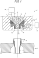
- a blow molding device 1 is a device that blow molds a bottomed tubular preform 2 having a mouth portion 2a into a container C (see FIG. 3 ).
- the blow molding device 1 includes a mold 3 in which the preform 2 can be placed.
- the mold 3 has a bottle-shaped cavity 4 (only partially illustrated in the drawing) that is open on the upper surface of the mold 3.
- the preform 2 is placed in the mold 3 in a standing position with the mouth portion 2a being on the upper side.
- the mouth portion 2a projects upward from the cavity 4.
- the mold 3 is openable right and left, and the molded container C can be taken out of the mold 3 by opening the mold 3, although not illustrated in detail.
- the preform 2 can be obtained, for example, by forming a thermoplastic resin material that develops stretchability as a result of heating, such as polypropylene (PP), polyethylene terephthalate (PET), or polyethylene (PE), in a bottomed tubular shape by injection molding, compression molding, extrusion molding, or the like.
- a thermoplastic resin material that develops stretchability as a result of heating such as polypropylene (PP), polyethylene terephthalate (PET), or polyethylene (PE)
- PP polypropylene
- PET polyethylene terephthalate
- PE polyethylene
- a nozzle unit 5 is provided above the mold 3 so as to be movable in the vertical direction relative to the mold 3.
- the nozzle unit 5 includes a main block 6.
- the main block 6 is a combination of a plurality of members, although its detailed description and illustration are omitted.
- the nozzle unit 5 includes a tubular nozzle 7 that can engage with the mouth portion 2a of the preform 2.
- the nozzle 7 has a nozzle tip 7a formed in a cylindrical shape whose outer diameter is smaller than the inner diameter of the mouth portion 2a of the preform 2 so that the lower end surface of the nozzle tip 7a will abut a step portion formed on the inner surface of the mouth portion 2a of the preform 2.
- the outer diameter of the nozzle tip 7a may be equal to the inner diameter of the mouth portion 2a of the preform 2 so that the outer circumferential surface of the nozzle tip 7a will abut the inner circumferential surface of the mouth portion 2a.
- the nozzle 7 can engage with the mouth portion 2a.
- the nozzle 7 also has a sandwiched portion 7b integrally provided above the nozzle tip 7a, and is sandwiched and fixed by the inner surface of the main block 6 at the sandwiched portion 7b.
- the nozzle 7 may be made of a steel material, a resin material, or the like.
- the nozzle 7 is located coaxially with the cavity 4 of the mold 3. Hence, as a result of the nozzle unit 5 being lowered to a predetermined position, the nozzle tip 7a can be inserted into the mouth portion 2a of the preform 2 placed in the mold 3.
- a supply path 8 extending in the vertical direction is formed inside the main block 6.
- the supply path 8 is connected to the nozzle 7 from above.
- the supply path 8 is also connected to a pressurized fluid supply source 10 through a piping 9.
- the pressurized fluid supply source 10 can supply an incompressible fluid pressurized to a predetermined pressure to the nozzle 7 through the piping 9 and the supply path 8. That is, the pressurized fluid supply source 10 can supply the pressurized incompressible fluid to the preform 2 through the piping 9, the supply path 8, and the nozzle 7 during blow molding.
- the pressurized fluid supply source 10 for example, a plunger pump is preferably used as a pressurization source.
- the pressurized fluid supply source 10 may have any other structure as long as it can supply the incompressible fluid pressurized to the predetermined pressure to the supply path 8.
- the incompressible fluid supplied from the pressurized fluid supply source 10 to the nozzle 7, i.e. the preform 2 for example, a liquid with relatively high viscosity, such as a shampoo or a liquid detergent, may be used.
- the viscosity of the incompressible fluid when supplied to the preform 2 is preferably 10000 mPa ⁇ s or less.
- a tubular seal body 11 for opening and closing the nozzle 7 is placed in the supply path 8.
- the seal body 11 is movable in the vertical direction between a closed position in which the seal body 11 abuts the nozzle 7 from above and closes the nozzle 7 and an open position in which the seal body 11 separates from the nozzle 7 and opens the nozzle 7.
- the seal body 11 includes a cylindrical shaft body (not illustrated), a cylindrical large-diameter portion 11a integrally connected to the lower end of the shaft body and having an outer diameter larger than the shaft body, and a cylindrical tubular wall 11b integrally connected to the lower end of the large-diameter portion 11a and having an outer diameter smaller than the large-diameter portion 11a.
- a downward-pointing conical inclined surface 12 is provided at the lower end of the large-diameter portion 11a.
- the seal body 11 is a single member made of a steel material, a resin material, or the like. Alternatively, the seal body 11 may be composed of a plurality of members.
- a downward-pointing conical closed surface 15 is provided at the upper surface of the nozzle 7, i.e. the upper surface of the sandwiched portion 7b of the nozzle 7.
- the seal body 11 moving to the closed position that is the lower stroke end and the inclined surface 12 provided at the lower end of the large-diameter portion 11a abutting the closed surface 15 from above, the communication between the supply path 8 and the nozzle tip 7a can be blocked by the seal body 11 to close the nozzle 7.
- the seal body 11 moving upward from the closed position to the open position and the inclined surface 12 separating upward from the closed surface 15 of the nozzle 7, the supply path 8 and the nozzle tip 7a can communicate with each other to open the nozzle 7.
- each of the inclined surface 12 and the closed surface 15 may be changed as appropriate.
- the nozzle 7 may be closed and opened by the outer circumferential surface of the tubular wall 11b and the inner circumferential surface of the nozzle 7 abutting and separating from each other.
- the pressurized incompressible fluid can be supplied from the pressurized fluid supply source 10 into the preform 2 through the nozzle 7 to blow mold the preform 2.
- the nozzle 7 being closed by the seal body 11 after the blow molding, the supply of the incompressible fluid into the molded container C can be stopped.
- the blow molding device 1 includes a rod 16 surrounded by the seal body 11 and movable in the vertical direction.
- the rod 16 is used as a rod for biaxial stretching.
- the rod 16 is hereafter also referred to as "stretching rod 16".
- the stretching rod 16 is slidably installed in a hole formed at the axial center of the seal body 11, and is movable in the axial direction, i.e. the vertical direction, relative to the seal body 11.
- the preform 2 placed in the mold 3 can be stretched inside the cavity 4 in the axial direction (longitudinal direction) by the stretching rod 16.
- the stretching rod 16 has a solid columnar shape.
- the inner circumferential surface of the nozzle 7 (the nozzle tip 7a and the sandwiched portion 7b) is a cylindrical inner circumferential surface.
- the tubular wall 11b of the seal body 11 has an outer circumferential surface that faces the inner circumferential surface of the nozzle 7 when the seal body 11 is in the closed position.
- a slight gap is provided between the outer circumferential surface of the tubular wall 11b and the inner circumferential surface of the nozzle 7 to reduce the sliding resistance therebetween.
- the outer circumferential surface of the tubular wall 11b may be configured to be in sliding contact with the inner circumferential surface of the nozzle 7.
- the tubular wall 11b has its lower end flush with the lower end of the nozzle tip 7a when the seal body 11 is in the closed position.
- the blow molding device 1 includes a suction mechanism to prevent the incompressible fluid from dripping from the stretching rod 16, the seal body 11, and the nozzle 7 after blow molding.
- the suction mechanism includes: a communication depression 17 provided in the inner circumferential surface of the seal body 11; a communication port 18 open on the outer circumferential surface of the tubular wall 11b; a communication path 20 provided in the nozzle 7; and a fluid suction source 22 connected to the communication path 20 via an on-off valve 21.
- the communication path 20 is composed of eight radial passages 20a arranged at regular intervals in the circumferential direction, as illustrated in FIGS. 1 and 2 .
- Each radial passage 20a has a cylindrical inner circumferential surface shape extending in the radial direction from one end open on the inner circumferential surface of the sandwiched portion 7b to the other end open on the outer circumferential surface of the sandwiched portion 7b.
- Each radial passage 20a may have a sectional shape other than circular, and may extend in a direction inclined in at least one of the axial direction and the circumferential direction with respect to the radial direction.
- a ring-shaped depression 19 concentric with the central axis O is provided in the outer circumferential surface of the sandwiched portion 7b, and the other end of each radial passage 20a is open to the ring-shaped depression 19.
- the ring-shaped depression 19 forms a ring-shaped passage 23 together with the inner circumferential surface of the main block 6.
- the other end of each radial passage 20a is connected to the fluid suction source 22 through the ring-shaped passage 23 and the on-off valve 21.
- the concave communication depression 17 extending from the lower end of the tubular wall 11b to the communication port 18 open on the outer circumferential surface of the tubular wall 11b is provided in the inner circumferential surface of the seal body 11.
- the communication depression 17 is composed of eight vertical grooves 17a arranged at regular intervals in the circumferential direction of the tubular wall 11b and each extending in the vertical direction.
- Each vertical groove 17a has a U cross-sectional shape that is open radially inward throughout its length (the vertical direction).
- the cross-sectional shape of each vertical groove 17a is, however, not limited to such U-shape.
- each vertical groove 17a is not limited to extending in the vertical direction.
- each vertical groove 17a may extend spirally about the central axis O.
- the inner circumferential surface of the tubular wall 11b located between the eight vertical grooves 17a is configured to be in contact with the outer circumferential surface of the stretching rod 16.
- the tubular wall 11b can thus serve to guide the stretching rod 16.
- the inner circumferential surface of the tubular wall 11b located between the eight vertical grooves 17a may be configured to be not in contact with the outer circumferential surface of the stretching rod 16.
- Each vertical groove 17a extends to the lower end of the tubular wall 11b at its lower end.
- Each vertical groove 17a extends to the communication port 18 at its upper end.
- the communication port 18 is composed of an opening 18a of a cylindrical inner circumferential surface shape connected to the upper end of each of the eight vertical grooves 17a. That is, the communication port 18 is composed of eight openings 18a.
- the eight sets of vertical grooves 17a, openings 18a, and radial passages 20a may be arranged not at regular intervals in the circumferential direction.
- the cross-sectional areas of the vertical grooves 17a may be different from each other.
- the number of sets of vertical grooves 17a, openings 18a, and radial passages 20a is not limited to eight, and may be changed as appropriate.
- the communication port 18 may extend in the circumferential direction with respect to the central axis O and communicate with the plurality of vertical grooves 17a. In this case, the number of vertical grooves 17a and the number of radial passages 20a may be different from each other.
- the number of radial passages 20a may be one, with the on-off valve 21 being connected to the other end of the radial passage 20a (i.e. the ring-shaped passage 23 is not provided).
- the on-off valve 21 being connected to the other end of the radial passage 20a (i.e. the ring-shaped passage 23 is not provided).
- FIGS. 1 and 2 etc., only one vertical groove 17a, one opening 18a, and one radial passage 20a are given reference signs, for the sake of convenience.
- the communication depression 17 is not limited to being composed of the vertical grooves 17a.
- the communication depression 17 may be composed of the vertical grooves 17a and one or more annular grooves extending all around the central axis O.
- the communication depression 17 may be composed of an annular depression extending from the lower end of the tubular wall 11b to the communication port 18 and also extending all around the central axis O.
- the on-off valve 21 is preferably provided inside the nozzle unit 5, but may be provided outside the nozzle unit 5.
- the on-off valve 21 is a motor-operated control valve, and can be opened and closed by a control means (not illustrated).
- the on-off valve 21 may be, for example, a pneumatic or hydraulic control valve.
- the fluid suction source 22 is formed by, for example, a vacuum pump, and can suck the incompressible fluid from the ring-shaped passage 23 and the communication path 20 when the on-off valve 21 is open.
- the fluid suction source 22 can suck the incompressible fluid adhering to the lower ends of these parts through the communication depression 17, the communication port 18, the communication path 20, and the ring-shaped passage 23 to prevent the incompressible fluid from dripping down.
- the preform 2 is placed in the mold 3 in a state in which the seal body 11 is in the closed position to close the nozzle 7.
- the nozzle unit 5 is lowered and the nozzle tip 7a is inserted into the mouth portion 2a of the preform 2.
- the stretching rod 16 is at an origin position at which its lower end is flush with the lower end of the tubular wall 11b of the seal body 11.
- the seal body 11 is then moved to the open position to open the nozzle 7.
- the pressurized incompressible fluid is supplied from the pressurized fluid supply source 10 into the preform 2 through the supply path 8 and the nozzle 7, and the preform 2 undergoes blow molding (liquid blow molding) by the incompressible fluid.
- the stretching rod 16 is lowered to stretch the preform 2 in the axial direction (longitudinal direction).
- the preform 2 is molded into the container C of a bottle shape along the cavity 4 of the mold 3, as illustrated in FIG. 3 .
- the seal body 11 is lowered to the closed position to close the nozzle 7, thus stopping the supply of the incompressible fluid.
- the stretching rod 16 is raised to the origin position, i.e. the position at which its lower end is flush with the lower end of the tubular wall 11b of the seal body 11 as indicated by a dashed-two dotted line in FIG. 4 .
- the nozzle unit 5 is then raised to separate the nozzle tip 7a upward from the mouth portion Ca of the container C, as illustrated in FIG. 4 .
- the timing at which the stretching rod 16 is raised to the origin position may be before or after the nozzle tip 7a separates from the mouth portion Ca of the container C.
- the stretching rod 16 being raised and removed from the incompressible fluid inside the container C, a headspace corresponding to the volume of the removed stretching rod is formed inside the container C.
- the headspace may be formed by any other method.
- the rod 16 may be used not as a rod for biaxial stretching but as a rod for headspace formation.
- the on-off valve 21 is opened and the fluid suction source 22 starts operation, as a result of which the incompressible fluid adhering to the nozzle tip 7a, the tubular wall 11b, and the lower end of the stretching rod 16 is sucked through the communication depression 17, the communication port 18, the communication path 20, and the ring-shaped passage 23 as indicated by dashed arrows in FIG. 4 .
- the incompressible fluid adhering to the outer circumferential surface of the stretching rod 16 can be directly sucked from the communication depression 17 provided in the inner circumferential surface of the seal body 11, so that the incompressible fluid adhering to the outer circumferential surface of the stretching rod 16 can be sucked effectively.
- the stretching rod 16 is squeezed by the seal body 11, so that the incompressible fluid adhering to the outer circumferential surface of the stretching rod 16 can be accumulated near the upper end of the communication depression 17. This also contributes to effective suction of the incompressible fluid adhering to the outer circumferential surface of the stretching rod 16.
- the communication depression 17 extending from the lower end of the tubular wall 11b to the communication port 18 is provided in the inner circumferential surface of the seal body 11. Therefore, not only the incompressible fluid adhering to the nozzle tip 7a, the tubular wall 11b, and the lower end of the stretching rod 16 but also the incompressible fluid adhering to the outer circumferential surface of the stretching rod 16 can be effectively sucked by the communication depression 17 to prevent the incompressible fluid from dripping from the nozzle 7, thus preventing the incompressible fluid from adhering to the molded container C or the mold 3.
- the incompressible fluid is a liquid with relatively high viscosity such as a shampoo or a liquid detergent
- the blow molding device 1 can prevent the liquid from dripping down and efficiently perform blow molding without increasing the cycle time.
- the stretching rod 16 may be raised to a position at which its lower end is flush with the upper end of the communication depression 17 as indicated by a solid line in FIG. 4 , and, in this state, the incompressible fluid adhering to the lower end of the stretching rod 16 may be sucked through the communication depression 17, the communication port 18, and the communication path 20.
- the timing at which the stretching rod 16 is raised to this position may be before or after the nozzle tip 7a separates from the mouth portion Ca of the container C. In this way, the incompressible fluid adhering to the lower end of the stretching rod 16 can be sucked efficiently.
- the stretching rod 16 After sucking the incompressible fluid adhering to the lower end of the stretching rod 16 in this way, the stretching rod 16 may be lowered to the origin position, and, in this state, the incompressible fluid adhering to the nozzle tip 7a, the tubular wall 11b, and the lower end of the stretching rod 16 may be sucked through the communication depression 17, the communication port 18, and the communication path 20. In this way, the incompressible fluid can be sucked more efficiently.
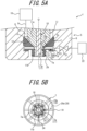
- a nozzle 7 has eight vertical holes 24 open to the lower end of the nozzle tip 7a, and three annular grooves 25 provided in the inner circumferential surface of the nozzle 7 and shaped like a ring around the central axis O.
- FIGS. 5A and 5B only one vertical hole 24 and one annular groove 25 are given reference signs, for the sake of convenience.
- the mold 3 and the preform 2 are not illustrated in FIG. 5A .
- the parts corresponding to those in the foregoing embodiment are given the same reference signs.
- Each vertical hole 24 extends in the vertical direction, and is open to the radial passage 20a at its upper end.
- the three annular grooves 25 are arranged in the axial direction. Each annular groove 25 intersects with the eight vertical holes 24, and forms an opening at each intersection.
- the number of vertical holes 24 may be changed as appropriate according to the number of radial passages.
- the number of annular grooves 25 may be changed as appropriate.
- the annular grooves 25 may be omitted.
- the other components are the same as those in the foregoing embodiment.
- the incompressible fluid can be sucked not only from the communication depression 17 but also from the vertical holes 24 and the annular grooves 25 provided in the nozzle 7, so that the incompressible fluid adhering to the nozzle tip 7a, the tubular wall 11b, and the lower end of the stretching rod 16 can be sucked particularly effectively.
- blow molding device 1 Another modification of the blow molding device 1 will be described below.
- a blow molding device 1 As illustrated in FIGS. 6A and 6B , a blow molding device 1 according to this modification has a communication depression 17 composed of ten vertical grooves 17a arranged at regular intervals in the circumferential direction of the tubular wall 11b and each extending in the vertical direction.
- a concave outer communication depression 26 extending from the lower end of the tubular wall 11b to the communication port 18 is provided in the outer circumferential surface of the seal body 11.
- the outer communication depression 26 is composed of eight outer vertical grooves arranged at regular intervals in the circumferential direction of the tubular wall 11b and each extending in the vertical direction.
- Each outer vertical groove 26a has a U cross-sectional shape that is open radially outward throughout its length (the vertical direction).
- the cross-sectional shape of each outer vertical groove 26a is, however, not limited to such U-shape.
- each outer vertical groove 26a is not limited to extending in the vertical direction.
- each outer vertical groove 26a may extend spirally about the central axis O.
- the outer circumferential surface of the tubular wall 11b located between the eight outer vertical grooves 26a may be spaced from or in contact with the inner circumferential surface of the nozzle tip 7a.
- Each outer vertical groove 26a extends to the lower end of the tubular wall 11b at its lower end.
- Each outer vertical groove 26a extends to the communication port 18 at its upper end.
- the communication port 18 is composed of an annular groove 18b provided in the outer circumferential surface of the seal body 11, connected to the upper end of each outer vertical groove 26a, and centered at the central axis O, and an opening 18a of a cylindrical inner circumferential surface shape connecting the upper end of each of the ten vertical grooves 17a to the annular groove 18b.
- the communication path 20 is composed of one radial passage 20a.
- the radial passage 20a has one end connected to the annular groove 18b, and the other end connected to the on-off valve 21.
- FIGS. 6A and 6B only one vertical groove 17a, one opening 18a, and one outer vertical groove 26a are given reference signs, for the sake of convenience.
- the mold 3 and the preform 2 are not illustrated in FIG. 6A .
- FIGS. 6A and 6B the parts corresponding to those in the foregoing embodiment are given the same reference signs.
- the ten sets of vertical grooves 17a and openings 18a may be arranged not at regular intervals in the circumferential direction.
- the eight outer vertical grooves 26a may be arranged not at regular intervals in the circumferential direction.
- the cross-sectional areas of the outer vertical grooves 26a may be different from each other.
- the number of sets of vertical grooves 17a and openings 18a is not limited to ten, and may be changed as appropriate.
- the number of outer vertical grooves 26a is not limited to eight, and may be changed as appropriate.
- the communication port 18 is not limited to be composed of the annular groove 18b and the openings 18a. In this modification, the shape of each vertical groove 17a may be changed as mentioned above.
- the communication depression 17 is not limited to be composed of the vertical grooves 17a, and may be changed as mentioned above.
- the incompressible fluid can be sucked not only from the communication depression 17 but also from the outer communication depression 26 provided in the outer circumferential surface of the seal body 11, so that the incompressible fluid adhering to the nozzle tip 7a, the tubular wall 11b, and the lower end of the stretching rod 16 can be sucked particularly effectively.
- the blow molding device 1 includes the fluid suction source 22 capable of sucking the incompressible fluid from the communication depression 17 through the on-off valve 21, the communication path 20, and the communication port 18.
- the blow molding device 1 may include, instead of or in addition to the fluid suction source 22, a pressurized gas supply source capable of supplying a pressurized gas that blows off the incompressible fluid from the communication depression 17 (or the communication depression 17 and the outer communication depression 26) through the on-off valve 21, the communication path 20, and the communication port 18.
- the pressurized gas supply source may be formed by a plunger pump.
- the nozzle tip 7a and the tubular wall 11b are cylindrical.
- the nozzle tip 7a and the tubular wall 11b may be tubular with a sectional shape such as polygonal or elliptic.
- the outer circumferential surface of the nozzle tip 7a is cylindrical.
- the lower end of the tubular wall 11b may have an annular inclined surface inclined upward to the radial inner side, from its outer circumferential edge to its inner circumferential edge.
- the lower end of the tubular wall 11b may be composed of an annular horizontal surface and an annular inclined surface located on the radial inner side of the annular horizontal surface. In such a case, the position at which the lower end of the rod 16 coincides with the upper end of the annular inclined surface can be set as the origin position of the rod 16 .
- the rod 16 is shaped like a solid column.
- the rod 16 may internally have a flow path connected to the pressurized fluid supply source 10.
- the rod 16 may be, for example, composed of a cylindrical outer tube and a poppet valve-shaped opening/closing rod capable of opening and closing the lower end of the outer tube.
- a prefilling step of prefilling the preform 2 with the incompressible fluid through the flow path inside the rod 16 before the blow molding may be performed.
- a suck back step of sucking the incompressible fluid from inside the blow-molded container C back to the pressurized fluid supply source 10 through the flow path inside the rod 16 may be performed.
- an air discharge path that can be opened and closed may be provided in the ring-shaped passage 23.
- the rod 16 may or may not be used as a rod for biaxial stretching.
- the tubular wall 11b is configured so that its lower end is flush with the lower end of the nozzle tip 7a when the seal body 11 is in the closed position.
- the tubular wall 11b may be configured so that its lower end is located higher or lower than the lower end of the nozzle tip 7a when the seal body 11 is in the closed position, depending on the type of the incompressible fluid and the like.
Landscapes
- Engineering & Computer Science (AREA)
- Manufacturing & Machinery (AREA)
- Mechanical Engineering (AREA)
- Blow-Moulding Or Thermoforming Of Plastics Or The Like (AREA)
- Basic Packing Technique (AREA)
Claims (4)
- Un dispositif de moulage par soufflage comprenant : une buse tubulaire (7) ; une source de fourniture de fluide sous pression (10) configurée pour fournir un fluide incompressible sous pression à la buse (7) ; un corps d'étanchéité tubulaire (11) configuré pour se déplacer dans une direction verticale entre une position fermée dans laquelle la buse (7) est fermée et une position ouverte dans laquelle la buse (7) est ouverte ; et une tige (16) ayant une surface circonférentielle extérieure qui fait face à une surface circonférentielle intérieure du corps d'étanchéité (11), et configurée pour se déplacer dans la direction verticale, dans lequel le corps d'étanchéité (11) inclut une paroi tubulaire (11B) ayant une surface circonférentielle extérieure qui fait face à la buse (7) quand le corps d'étanchéité (11) est dans la position fermée, un creux de communication concave (17) s'étendant d'une extrémité inférieure de la paroi tubulaire (11B) à un orifice de communication (18) ouvert sur la surface circonférentielle extérieure de la paroi tubulaire (11B) est ménagé dans la surface circonférentielle intérieure du corps d'étanchéité (11), un chemin de communication (20) qui communique avec l'orifice de communication (18) quand le corps d'étanchéité (11) est dans la position fermée est ménagé dans la buse (7), et le dispositif de moulage par soufflage comprend en outre au moins un élément parmi : une source d'aspiration de fluide (22) configurée pour aspirer le fluide incompressible présent dans le creux de communication (17) par l'intermédiaire du chemin de communication (20) et de l'orifice de communication (18) ; et une source de fourniture de gaz sous pression configurée pour fournir un gaz sous pression qui chasse le fluide incompressible du creux de communication (17) par l'intermédiaire du chemin de communication (20) et de l'orifice de communication (18).
- Le dispositif de moulage par soufflage selon la revendication 1, dans lequel le creux de communication (17) est composé d'une pluralité de gorges verticales (17A) agencées à intervalles réguliers dans une direction circonférentielle de la paroi tubulaire (11B) et s'étendant chacune dans la direction verticale, et une surface circonférentielle intérieure de la paroi tubulaire (11B) située entre la pluralité de gorges verticales (17A) vient en contact avec la surface circonférentielle extérieure de la tige (16).
- Le dispositif de moulage par soufflage selon la revendication 1 ou la revendication 2, dans lequel un creux de communication extérieur concave (26) s'étendant de l'extrémité inférieure de la paroi tubulaire (11B) à l'orifice de communication (18) est ménagé dans une surface circonférentielle extérieure du corps d'étanchéité (11).
- Le dispositif de moulage par soufflage selon la revendication 3, dans lequel le creux de communication extérieur (26) est composé d'une pluralité de gorges verticales extérieures (26A) agencées à intervalles réguliers dans une direction circonférentielle de la paroi tubulaire (11B) et s'étendant chacune dans la direction verticale.
Applications Claiming Priority (3)
| Application Number | Priority Date | Filing Date | Title |
|---|---|---|---|
| JP2018221595 | 2018-11-27 | ||
| JP2019173505A JP7217686B2 (ja) | 2018-11-27 | 2019-09-24 | ブロー成形装置 |
| PCT/JP2019/041392 WO2020110516A1 (fr) | 2018-11-27 | 2019-10-21 | Dispositif de moulage par soufflage |
Publications (3)
| Publication Number | Publication Date |
|---|---|
| EP3888882A1 EP3888882A1 (fr) | 2021-10-06 |
| EP3888882A4 EP3888882A4 (fr) | 2022-08-03 |
| EP3888882B1 true EP3888882B1 (fr) | 2023-05-10 |
Family
ID=71012195
Family Applications (1)
| Application Number | Title | Priority Date | Filing Date |
|---|---|---|---|
| EP19889030.3A Active EP3888882B1 (fr) | 2018-11-27 | 2019-10-21 | Dispositif de moulage par soufflage |
Country Status (4)
| Country | Link |
|---|---|
| US (1) | US11345072B2 (fr) |
| EP (1) | EP3888882B1 (fr) |
| JP (1) | JP7217686B2 (fr) |
| CN (1) | CN113165252B (fr) |
Family Cites Families (19)
| Publication number | Priority date | Publication date | Assignee | Title |
|---|---|---|---|---|
| US5114659A (en) * | 1988-02-25 | 1992-05-19 | Owens-Illinois Plastic Products Inc. | Blow molding method for forming a one-piece self-draining container |
| JP3860886B2 (ja) * | 1997-07-17 | 2006-12-20 | 三菱重工食品包装機械株式会社 | 充填ノズル及び液体充填方法 |
| JP4350224B2 (ja) * | 1999-09-07 | 2009-10-21 | 三菱重工食品包装機械株式会社 | 液体充填装置および方法 |
| US6485669B1 (en) * | 1999-09-14 | 2002-11-26 | Schmalbach-Lubeca Ag | Blow molding method for producing pasteurizable containers |
| DE102004000046B3 (de) * | 2004-11-17 | 2005-12-08 | Mann + Hummel Gmbh | Luftführungskanal |
| JP5872361B2 (ja) | 2012-03-30 | 2016-03-01 | 株式会社吉野工業所 | ブロー成形装置及び合成樹脂製容器の製造方法 |
| JP6100137B2 (ja) * | 2013-09-30 | 2017-03-22 | 株式会社吉野工業所 | ブロー成形装置 |
| JP6450617B2 (ja) * | 2015-03-13 | 2019-01-09 | 株式会社吉野工業所 | ブロー成形装置 |
| JP6450616B2 (ja) * | 2015-03-13 | 2019-01-09 | 株式会社吉野工業所 | ブロー成形装置 |
| US10189202B2 (en) * | 2015-03-13 | 2019-01-29 | Discma Ag | Blow molding device |
| WO2018079012A1 (fr) * | 2016-10-28 | 2018-05-03 | 株式会社吉野工業所 | Procédé de moulage par soufflage de liquide |
| JP6760819B2 (ja) * | 2016-10-31 | 2020-09-23 | 株式会社吉野工業所 | 液体ブロー成形装置及びプリフォーム |
| JP6864570B2 (ja) * | 2017-04-27 | 2021-04-28 | 株式会社吉野工業所 | 液体入り容器の製造方法 |
| JP6864569B2 (ja) * | 2017-06-28 | 2021-04-28 | 株式会社吉野工業所 | 液体入り容器の製造方法 |
| JP6864578B2 (ja) * | 2017-07-31 | 2021-04-28 | 株式会社吉野工業所 | 液体入り容器の製造装置及び製造方法 |
| JP6909170B2 (ja) * | 2018-01-31 | 2021-07-28 | 株式会社吉野工業所 | ブロー成形装置 |
| JP7121692B2 (ja) * | 2019-05-30 | 2022-08-18 | 株式会社吉野工業所 | 液体ブロー成形装置 |
| JP7217685B2 (ja) * | 2019-08-30 | 2023-02-03 | 株式会社吉野工業所 | ブロー成形装置 |
| JP2021070220A (ja) * | 2019-10-30 | 2021-05-06 | 株式会社吉野工業所 | 液体ブロー成形装置 |
-
2019
- 2019-09-24 JP JP2019173505A patent/JP7217686B2/ja active Active
- 2019-10-21 US US17/295,977 patent/US11345072B2/en active Active
- 2019-10-21 CN CN201980077478.5A patent/CN113165252B/zh active Active
- 2019-10-21 EP EP19889030.3A patent/EP3888882B1/fr active Active
Also Published As
| Publication number | Publication date |
|---|---|
| JP2020090087A (ja) | 2020-06-11 |
| EP3888882A1 (fr) | 2021-10-06 |
| JP7217686B2 (ja) | 2023-02-03 |
| CN113165252A (zh) | 2021-07-23 |
| US11345072B2 (en) | 2022-05-31 |
| CN113165252B (zh) | 2023-04-14 |
| US20210394421A1 (en) | 2021-12-23 |
| EP3888882A4 (fr) | 2022-08-03 |
Similar Documents
| Publication | Publication Date | Title |
|---|---|---|
| EP3747622B1 (fr) | Dispositif de moulage par soufflage | |
| EP3845361B1 (fr) | Procédé de fabrication d'un récipient rempli de liquide | |
| EP3269530B1 (fr) | Dispositif de moulage par soufflage | |
| EP3663071B1 (fr) | Dispositif et procédé de fabrication d'un récipient rempli de liquide | |
| EP3533584B1 (fr) | Procédé de moulage par soufflage de liquide | |
| EP3647017B1 (fr) | Méthode de fabrication d'un récipient rempli de liquide | |
| EP3685985B1 (fr) | Procédé de fabrication d'un récipient contenant un liquide | |
| EP3616880B1 (fr) | Procédé pour la fabrication d'un récipient pour liquides | |
| CN110382203B (zh) | 容器制造方法 | |
| EP3978222B1 (fr) | Dispositif de moulage par soufflage | |
| EP3888882B1 (fr) | Dispositif de moulage par soufflage | |
| EP3632652A1 (fr) | Méthode de fabrication de récipient de liquide | |
| US12358204B2 (en) | Method for manufacturing liquid container | |
| WO2020110516A1 (fr) | Dispositif de moulage par soufflage |
Legal Events
| Date | Code | Title | Description |
|---|---|---|---|
| STAA | Information on the status of an ep patent application or granted ep patent |
Free format text: STATUS: THE INTERNATIONAL PUBLICATION HAS BEEN MADE |
|
| PUAI | Public reference made under article 153(3) epc to a published international application that has entered the european phase |
Free format text: ORIGINAL CODE: 0009012 |
|
| STAA | Information on the status of an ep patent application or granted ep patent |
Free format text: STATUS: REQUEST FOR EXAMINATION WAS MADE |
|
| 17P | Request for examination filed |
Effective date: 20210527 |
|
| AK | Designated contracting states |
Kind code of ref document: A1 Designated state(s): AL AT BE BG CH CY CZ DE DK EE ES FI FR GB GR HR HU IE IS IT LI LT LU LV MC MK MT NL NO PL PT RO RS SE SI SK SM TR |
|
| DAV | Request for validation of the european patent (deleted) | ||
| DAX | Request for extension of the european patent (deleted) | ||
| A4 | Supplementary search report drawn up and despatched |
Effective date: 20220704 |
|
| RIC1 | Information provided on ipc code assigned before grant |
Ipc: B29L 31/00 20060101ALN20220628BHEP Ipc: B29C 49/12 20060101ALN20220628BHEP Ipc: B29C 49/02 20060101ALN20220628BHEP Ipc: B29C 49/46 20060101ALI20220628BHEP Ipc: B29C 49/58 20060101AFI20220628BHEP |
|
| REG | Reference to a national code |
Ref country code: DE Free format text: PREVIOUS MAIN CLASS: B29C0049120000 Ref country code: DE Ref legal event code: R079 Ref document number: 602019028932 Country of ref document: DE Free format text: PREVIOUS MAIN CLASS: B29C0049120000 Ipc: B29C0049580000 |
|
| GRAP | Despatch of communication of intention to grant a patent |
Free format text: ORIGINAL CODE: EPIDOSNIGR1 |
|
| STAA | Information on the status of an ep patent application or granted ep patent |
Free format text: STATUS: GRANT OF PATENT IS INTENDED |
|
| RIC1 | Information provided on ipc code assigned before grant |
Ipc: B29L 31/00 20060101ALN20230203BHEP Ipc: B29C 49/12 20060101ALN20230203BHEP Ipc: B29C 49/06 20060101ALN20230203BHEP Ipc: B29C 49/46 20060101ALI20230203BHEP Ipc: B29C 49/58 20060101AFI20230203BHEP |
|
| INTG | Intention to grant announced |
Effective date: 20230222 |
|
| GRAS | Grant fee paid |
Free format text: ORIGINAL CODE: EPIDOSNIGR3 |
|
| GRAA | (expected) grant |
Free format text: ORIGINAL CODE: 0009210 |
|
| STAA | Information on the status of an ep patent application or granted ep patent |
Free format text: STATUS: THE PATENT HAS BEEN GRANTED |
|
| AK | Designated contracting states |
Kind code of ref document: B1 Designated state(s): AL AT BE BG CH CY CZ DE DK EE ES FI FR GB GR HR HU IE IS IT LI LT LU LV MC MK MT NL NO PL PT RO RS SE SI SK SM TR |
|
| REG | Reference to a national code |
Ref country code: GB Ref legal event code: FG4D |
|
| RIN1 | Information on inventor provided before grant (corrected) |
Inventor name: OKUYAMA, YUICHI Inventor name: SHIOKAWA, MITSURU Inventor name: HOSHINO, HIDEAKI |
|
| REG | Reference to a national code |
Ref country code: AT Ref legal event code: REF Ref document number: 1566273 Country of ref document: AT Kind code of ref document: T Effective date: 20230515 Ref country code: CH Ref legal event code: EP |
|
| REG | Reference to a national code |
Ref country code: DE Ref legal event code: R096 Ref document number: 602019028932 Country of ref document: DE |
|
| REG | Reference to a national code |
Ref country code: IE Ref legal event code: FG4D |
|
| REG | Reference to a national code |
Ref country code: LT Ref legal event code: MG9D |
|
| REG | Reference to a national code |
Ref country code: NL Ref legal event code: MP Effective date: 20230510 |
|
| REG | Reference to a national code |
Ref country code: AT Ref legal event code: MK05 Ref document number: 1566273 Country of ref document: AT Kind code of ref document: T Effective date: 20230510 |
|
| PG25 | Lapsed in a contracting state [announced via postgrant information from national office to epo] |
Ref country code: SE Free format text: LAPSE BECAUSE OF FAILURE TO SUBMIT A TRANSLATION OF THE DESCRIPTION OR TO PAY THE FEE WITHIN THE PRESCRIBED TIME-LIMIT Effective date: 20230510 Ref country code: PT Free format text: LAPSE BECAUSE OF FAILURE TO SUBMIT A TRANSLATION OF THE DESCRIPTION OR TO PAY THE FEE WITHIN THE PRESCRIBED TIME-LIMIT Effective date: 20230911 Ref country code: NO Free format text: LAPSE BECAUSE OF FAILURE TO SUBMIT A TRANSLATION OF THE DESCRIPTION OR TO PAY THE FEE WITHIN THE PRESCRIBED TIME-LIMIT Effective date: 20230810 Ref country code: NL Free format text: LAPSE BECAUSE OF FAILURE TO SUBMIT A TRANSLATION OF THE DESCRIPTION OR TO PAY THE FEE WITHIN THE PRESCRIBED TIME-LIMIT Effective date: 20230510 Ref country code: ES Free format text: LAPSE BECAUSE OF FAILURE TO SUBMIT A TRANSLATION OF THE DESCRIPTION OR TO PAY THE FEE WITHIN THE PRESCRIBED TIME-LIMIT Effective date: 20230510 Ref country code: AT Free format text: LAPSE BECAUSE OF FAILURE TO SUBMIT A TRANSLATION OF THE DESCRIPTION OR TO PAY THE FEE WITHIN THE PRESCRIBED TIME-LIMIT Effective date: 20230510 |
|
| PG25 | Lapsed in a contracting state [announced via postgrant information from national office to epo] |
Ref country code: RS Free format text: LAPSE BECAUSE OF FAILURE TO SUBMIT A TRANSLATION OF THE DESCRIPTION OR TO PAY THE FEE WITHIN THE PRESCRIBED TIME-LIMIT Effective date: 20230510 Ref country code: PL Free format text: LAPSE BECAUSE OF FAILURE TO SUBMIT A TRANSLATION OF THE DESCRIPTION OR TO PAY THE FEE WITHIN THE PRESCRIBED TIME-LIMIT Effective date: 20230510 Ref country code: LV Free format text: LAPSE BECAUSE OF FAILURE TO SUBMIT A TRANSLATION OF THE DESCRIPTION OR TO PAY THE FEE WITHIN THE PRESCRIBED TIME-LIMIT Effective date: 20230510 Ref country code: LT Free format text: LAPSE BECAUSE OF FAILURE TO SUBMIT A TRANSLATION OF THE DESCRIPTION OR TO PAY THE FEE WITHIN THE PRESCRIBED TIME-LIMIT Effective date: 20230510 Ref country code: IS Free format text: LAPSE BECAUSE OF FAILURE TO SUBMIT A TRANSLATION OF THE DESCRIPTION OR TO PAY THE FEE WITHIN THE PRESCRIBED TIME-LIMIT Effective date: 20230910 Ref country code: HR Free format text: LAPSE BECAUSE OF FAILURE TO SUBMIT A TRANSLATION OF THE DESCRIPTION OR TO PAY THE FEE WITHIN THE PRESCRIBED TIME-LIMIT Effective date: 20230510 Ref country code: GR Free format text: LAPSE BECAUSE OF FAILURE TO SUBMIT A TRANSLATION OF THE DESCRIPTION OR TO PAY THE FEE WITHIN THE PRESCRIBED TIME-LIMIT Effective date: 20230811 |
|
| PG25 | Lapsed in a contracting state [announced via postgrant information from national office to epo] |
Ref country code: FI Free format text: LAPSE BECAUSE OF FAILURE TO SUBMIT A TRANSLATION OF THE DESCRIPTION OR TO PAY THE FEE WITHIN THE PRESCRIBED TIME-LIMIT Effective date: 20230510 |
|
| PG25 | Lapsed in a contracting state [announced via postgrant information from national office to epo] |
Ref country code: SK Free format text: LAPSE BECAUSE OF FAILURE TO SUBMIT A TRANSLATION OF THE DESCRIPTION OR TO PAY THE FEE WITHIN THE PRESCRIBED TIME-LIMIT Effective date: 20230510 |
|
| PG25 | Lapsed in a contracting state [announced via postgrant information from national office to epo] |
Ref country code: SM Free format text: LAPSE BECAUSE OF FAILURE TO SUBMIT A TRANSLATION OF THE DESCRIPTION OR TO PAY THE FEE WITHIN THE PRESCRIBED TIME-LIMIT Effective date: 20230510 Ref country code: SK Free format text: LAPSE BECAUSE OF FAILURE TO SUBMIT A TRANSLATION OF THE DESCRIPTION OR TO PAY THE FEE WITHIN THE PRESCRIBED TIME-LIMIT Effective date: 20230510 Ref country code: RO Free format text: LAPSE BECAUSE OF FAILURE TO SUBMIT A TRANSLATION OF THE DESCRIPTION OR TO PAY THE FEE WITHIN THE PRESCRIBED TIME-LIMIT Effective date: 20230510 Ref country code: EE Free format text: LAPSE BECAUSE OF FAILURE TO SUBMIT A TRANSLATION OF THE DESCRIPTION OR TO PAY THE FEE WITHIN THE PRESCRIBED TIME-LIMIT Effective date: 20230510 Ref country code: DK Free format text: LAPSE BECAUSE OF FAILURE TO SUBMIT A TRANSLATION OF THE DESCRIPTION OR TO PAY THE FEE WITHIN THE PRESCRIBED TIME-LIMIT Effective date: 20230510 Ref country code: CZ Free format text: LAPSE BECAUSE OF FAILURE TO SUBMIT A TRANSLATION OF THE DESCRIPTION OR TO PAY THE FEE WITHIN THE PRESCRIBED TIME-LIMIT Effective date: 20230510 |
|
| REG | Reference to a national code |
Ref country code: DE Ref legal event code: R097 Ref document number: 602019028932 Country of ref document: DE |
|
| PLBE | No opposition filed within time limit |
Free format text: ORIGINAL CODE: 0009261 |
|
| STAA | Information on the status of an ep patent application or granted ep patent |
Free format text: STATUS: NO OPPOSITION FILED WITHIN TIME LIMIT |
|
| 26N | No opposition filed |
Effective date: 20240213 |
|
| PG25 | Lapsed in a contracting state [announced via postgrant information from national office to epo] |
Ref country code: SI Free format text: LAPSE BECAUSE OF FAILURE TO SUBMIT A TRANSLATION OF THE DESCRIPTION OR TO PAY THE FEE WITHIN THE PRESCRIBED TIME-LIMIT Effective date: 20230510 |
|
| PG25 | Lapsed in a contracting state [announced via postgrant information from national office to epo] |
Ref country code: SI Free format text: LAPSE BECAUSE OF FAILURE TO SUBMIT A TRANSLATION OF THE DESCRIPTION OR TO PAY THE FEE WITHIN THE PRESCRIBED TIME-LIMIT Effective date: 20230510 Ref country code: IT Free format text: LAPSE BECAUSE OF FAILURE TO SUBMIT A TRANSLATION OF THE DESCRIPTION OR TO PAY THE FEE WITHIN THE PRESCRIBED TIME-LIMIT Effective date: 20230510 Ref country code: MC Free format text: LAPSE BECAUSE OF FAILURE TO SUBMIT A TRANSLATION OF THE DESCRIPTION OR TO PAY THE FEE WITHIN THE PRESCRIBED TIME-LIMIT Effective date: 20230510 |
|
| REG | Reference to a national code |
Ref country code: CH Ref legal event code: PL |
|
| REG | Reference to a national code |
Ref country code: BE Ref legal event code: MM Effective date: 20231031 |
|
| PG25 | Lapsed in a contracting state [announced via postgrant information from national office to epo] |
Ref country code: LU Free format text: LAPSE BECAUSE OF NON-PAYMENT OF DUE FEES Effective date: 20231021 |
|
| PG25 | Lapsed in a contracting state [announced via postgrant information from national office to epo] |
Ref country code: LU Free format text: LAPSE BECAUSE OF NON-PAYMENT OF DUE FEES Effective date: 20231021 |
|
| PG25 | Lapsed in a contracting state [announced via postgrant information from national office to epo] |
Ref country code: CH Free format text: LAPSE BECAUSE OF NON-PAYMENT OF DUE FEES Effective date: 20231031 |
|
| PG25 | Lapsed in a contracting state [announced via postgrant information from national office to epo] |
Ref country code: CH Free format text: LAPSE BECAUSE OF NON-PAYMENT OF DUE FEES Effective date: 20231031 |
|
| PG25 | Lapsed in a contracting state [announced via postgrant information from national office to epo] |
Ref country code: BE Free format text: LAPSE BECAUSE OF NON-PAYMENT OF DUE FEES Effective date: 20231031 |
|
| PG25 | Lapsed in a contracting state [announced via postgrant information from national office to epo] |
Ref country code: IE Free format text: LAPSE BECAUSE OF NON-PAYMENT OF DUE FEES Effective date: 20231021 |
|
| PG25 | Lapsed in a contracting state [announced via postgrant information from national office to epo] |
Ref country code: IE Free format text: LAPSE BECAUSE OF NON-PAYMENT OF DUE FEES Effective date: 20231021 |
|
| PG25 | Lapsed in a contracting state [announced via postgrant information from national office to epo] |
Ref country code: BG Free format text: LAPSE BECAUSE OF FAILURE TO SUBMIT A TRANSLATION OF THE DESCRIPTION OR TO PAY THE FEE WITHIN THE PRESCRIBED TIME-LIMIT Effective date: 20230510 |
|
| PG25 | Lapsed in a contracting state [announced via postgrant information from national office to epo] |
Ref country code: BG Free format text: LAPSE BECAUSE OF FAILURE TO SUBMIT A TRANSLATION OF THE DESCRIPTION OR TO PAY THE FEE WITHIN THE PRESCRIBED TIME-LIMIT Effective date: 20230510 |
|
| PG25 | Lapsed in a contracting state [announced via postgrant information from national office to epo] |
Ref country code: CY Free format text: LAPSE BECAUSE OF FAILURE TO SUBMIT A TRANSLATION OF THE DESCRIPTION OR TO PAY THE FEE WITHIN THE PRESCRIBED TIME-LIMIT; INVALID AB INITIO Effective date: 20191021 |
|
| PG25 | Lapsed in a contracting state [announced via postgrant information from national office to epo] |
Ref country code: HU Free format text: LAPSE BECAUSE OF FAILURE TO SUBMIT A TRANSLATION OF THE DESCRIPTION OR TO PAY THE FEE WITHIN THE PRESCRIBED TIME-LIMIT; INVALID AB INITIO Effective date: 20191021 |
|
| PGFP | Annual fee paid to national office [announced via postgrant information from national office to epo] |
Ref country code: GB Payment date: 20250828 Year of fee payment: 7 |
|
| PGFP | Annual fee paid to national office [announced via postgrant information from national office to epo] |
Ref country code: FR Payment date: 20250908 Year of fee payment: 7 |
|
| PG25 | Lapsed in a contracting state [announced via postgrant information from national office to epo] |
Ref country code: TR Free format text: LAPSE BECAUSE OF FAILURE TO SUBMIT A TRANSLATION OF THE DESCRIPTION OR TO PAY THE FEE WITHIN THE PRESCRIBED TIME-LIMIT Effective date: 20230510 |
|
| PGFP | Annual fee paid to national office [announced via postgrant information from national office to epo] |
Ref country code: DE Payment date: 20250902 Year of fee payment: 7 |