EP3889014B1 - Véhicule à enfourcher - Google Patents
Véhicule à enfourcher Download PDFInfo
- Publication number
- EP3889014B1 EP3889014B1 EP21159917.0A EP21159917A EP3889014B1 EP 3889014 B1 EP3889014 B1 EP 3889014B1 EP 21159917 A EP21159917 A EP 21159917A EP 3889014 B1 EP3889014 B1 EP 3889014B1
- Authority
- EP
- European Patent Office
- Prior art keywords
- vehicle
- cover
- regard
- edge
- guide groove
- Prior art date
- Legal status (The legal status is an assumption and is not a legal conclusion. Google has not performed a legal analysis and makes no representation as to the accuracy of the status listed.)
- Active
Links
Images





Classifications
-
- B—PERFORMING OPERATIONS; TRANSPORTING
- B62—LAND VEHICLES FOR TRAVELLING OTHERWISE THAN ON RAILS
- B62J—CYCLE SADDLES OR SEATS; AUXILIARY DEVICES OR ACCESSORIES SPECIALLY ADAPTED TO CYCLES AND NOT OTHERWISE PROVIDED FOR, e.g. ARTICLE CARRIERS OR CYCLE PROTECTORS
- B62J17/00—Weather guards for riders; Fairings or stream-lining parts not otherwise provided for
-
- B—PERFORMING OPERATIONS; TRANSPORTING
- B62—LAND VEHICLES FOR TRAVELLING OTHERWISE THAN ON RAILS
- B62J—CYCLE SADDLES OR SEATS; AUXILIARY DEVICES OR ACCESSORIES SPECIALLY ADAPTED TO CYCLES AND NOT OTHERWISE PROVIDED FOR, e.g. ARTICLE CARRIERS OR CYCLE PROTECTORS
- B62J25/00—Foot-rests; Knee grips; Passenger hand-grips
- B62J25/04—Floor-type foot rests
-
- B—PERFORMING OPERATIONS; TRANSPORTING
- B62—LAND VEHICLES FOR TRAVELLING OTHERWISE THAN ON RAILS
- B62K—CYCLES; CYCLE FRAMES; CYCLE STEERING DEVICES; RIDER-OPERATED TERMINAL CONTROLS SPECIALLY ADAPTED FOR CYCLES; CYCLE AXLE SUSPENSIONS; CYCLE SIDE-CARS, FORECARS, OR THE LIKE
- B62K2202/00—Motorised scooters
Definitions
- the present invention relates to a straddled vehicle.
- the leg shield is located in front of the rider's legs.
- the front center cover is located in front of the head pipe.
- the front side cover is connected to the front center cover.
- the front side cover extends rearward and downward from the front center cover and is connected to the leg shield.
- document JP H10 203456 A discloses an straddled vehicle comprising: a head pipe; a steering device turnably supported by the head pipe; a front wheel rotatably supported by the steering device; a front center cover arranged in front of the head pipe with regard to a vehicle front-rear direction and above the front wheel with regard to a vehicle vertical direction, and on at least one of a left side and a right side of the vehicle comprises a front side cover that is connected to the front center cover and overlaps with the steering device as seen in a vehicle side view; a seat arranged behind the head pipe with regard to the vehicle front-rear direction; a rear side cover arranged rearward of the front side cover and that extends forward with regard to the vehicle front-rear direction and from below the seat with regard to the vehicle vertical direction; a leg shield that extends laterally outward with regard to a vehicle width direction from the rear side cover; and a footrest surface connected to a lower portion with regard to the vehicle vertical direction of the rear side cover and arranged behind
- a straddled vehicle includes a head pipe, a steering device, a front wheel, a front center cover, a front side cover, a seat, a (rear) side cover, a leg shield, and a footrest surface.
- the steering device is turnably supported by the head pipe.
- the front wheel are rotatably supported by the steering device.
- the front center cover is arranged in front of the head pipe and above the front wheel.
- the front side cover is connected to the front center cover and overlaps the steering device as seen in a vehicle side view.
- the seat is located behind the head pipe.
- the side cover extends forward from below the seat.
- the leg shield extends laterally outward from the side cover.
- the footrest surface is connected to a bottom of the side cover and is arranged behind the leg shield.
- the leg shield includes an upper side edge, a lower side edge, and a step.
- the lower side edge is located below the upper side edge and laterally outward of the upper side edge.
- the step is located between the upper side edge and the lower side edge.
- the front side cover includes an inner cover, an outer cover, and a guide groove.
- the inner cover is connected to the upper side edge and extends forward from the upper side edge.
- the outer cover extends downward and rearward from the front center cover as seen in the vehicle side view, and is arranged laterally outward of the inner cover.
- the outer cover includes a lower rear edge and an upper rear edge.
- the lower rear edge is connected to the lower side edge.
- the upper rear edge is located above the lower rear edge and at least partially overlaps the inner cover as seen in the vehicle side view.
- the guide groove is connected to the step and extends rearward and downward. The guide groove closes between the outer cover and the inner cover.
- the water that has flowed into the inner cover is guided downward by the guide groove.
- the upper rear edge may have a shape that is recessed forward. In this case, water can be easily collected from the upper rear edge into the guide groove.
- a portion of the inner cover may be located rearward of the upper rear edge. In this case, water can be easily collected in the guide groove.
- the guide groove may close between the outer cover and the inner cover at a position forward of the upper rear edge. In this case, water guided by the guide groove is not easily affected by the running wind. As seen in the vehicle side view, the outer cover may overlap the entire guide groove. In this case, water guided by the guide groove is not easily affected by the running wind.
- the side cover may have a shape that is recessed laterally inward at a position behind the guide groove. In this case, the rider can place his / her foot inside the guide groove. Therefore, the rider's legs are less likely to get wet.
- An upper end of the guide groove may be located above a lower end of the seat.
- a lower end of the guide groove may be located below the lower end of the seat.
- the lower end of the guide groove may be located below a top of the front wheel. In this case, the water splashing from the front wheel can be easily collected in the guide groove.
- the outer cover may include an upper side surface and an intermediate side surface.
- the upper side surface may be located above the upper end of the guide groove.
- the intermediate side surface may be located below the upper end of the guide groove and above the lower end of the guide groove. As seen in a vehicle front view, the intermediate side surface may be located laterally outward of the upper side surface. In this case, the rider's legs are less likely to get wet.
- the outer cover may further include a lower side surface.
- the outer cover may be located below the lower end of the guide groove.
- the intermediate side surface may be located laterally outward of the lower side surface. In this case, the rider's legs are less likely to get wet.
- FIG. 1 is a side view of the straddled vehicle 1 according to the embodiment.
- FIG. 2 is a perspective view of the straddled vehicle 1.
- FIG. 3 is a top view of the straddled vehicle 1.
- the straddled vehicle 1 according to the present embodiment is a scooter.
- the straddled vehicle 1 includes a body frame 2, a steering device 3, a front wheel 4, a seat 5, a power unit 6, and a rear wheel 7.
- the front-rear, left-right directions are defined as the directions when viewed from the rider seated on the seat 5.
- the body frame 2 includes a head pipe 11, a down frame 12, a lower frame 13, and a rear frame 14.
- the head pipe 11 is arranged at a center of the vehicle in a vehicle width direction.
- the head pipe 11 extends forward and downward.
- the down frame 12 extends downward from the head pipe 11.
- the lower frame 13 extends rearward from a lower portion of the down frame 12.
- the rear frame 14 extends rearward and upward from a rear portion of the down frame 12.
- the steering device 3 is turnably supported by the head pipe 11.
- the steering device 3 rotatably supports the front wheel 4.
- the steering device 3 includes a front fork 16 and a handle member 17.
- the front fork 16 is turnably supported by the head pipe 11.
- the front wheel 4 is rotatably supported by the front fork 16.
- the handle member 17 can be operated by a rider to turn the front wheel 4.
- the seat 5 is arranged behind the head pipe 11.
- the seat 5 is arranged above the rear frame 14.
- the power unit 6 is arranged below the seat 5.
- the power unit 6 includes, for example, an internal combustion engine. Alternatively, the power unit 6 may include an electric motor.
- the rear wheel 7 is rotatably supported by the power unit 6.
- the straddled vehicle 1 includes a front center cover 21, a front back cover 22, a left front side cover 23, and a right front side cover 24.
- the front center cover 21 is arranged in front of the head pipe 11 and above the front wheel 4.
- a headlight 18 is arranged on the front center cover 21.
- the front back cover 22 is arranged behind the head pipe 11.
- the front back cover 22 is connected to the front center cover 21.
- the left front side cover 23 is connected to the front center cover 21 and the front back cover 22.
- the left front side cover 23 is arranged behind the front wheel 4 and on the left side of the front wheel 4.
- the left front side cover 23 overlaps with the steering device 3 as seen in the vehicle side view.
- the right front side cover 24 is connected to the front center cover 21 and the front back cover 22.
- the right front side cover 24 is arranged behind the front wheel 4 and on the right side of the front wheel 4.
- the right front side cover 24 overlaps the steering device 3 as seen in the vehicle side view.
- the straddled vehicle 1 includes a left leg shield 25, a right leg shield (not illustrated), a left (rear) side cover 26, a right (rear) side cover 27, a center cover 28, a handle cover 29, and an undercover 30.
- the left leg shield 25 extends to the left from the left side cover 26.
- the right leg shield extends to the right from the right side cover 27.
- the right leg shield has a similar structure except that it is symmetrical with the left leg shield 25.
- the left side cover 26 and the right side cover 27 extend forward from below the seat 5.
- the left side cover 26 and the right side cover 27 are arranged rearward of the left front side cover 23 and the right front side cover 24, respectively.
- the left side cover 26 is arranged below the seat 5 and between the seat 5 and the left leg shield 25.
- the left side cover 26 covers the rear frame 14 from the left side.
- the right side cover 27 is arranged below the seat 5 and between the seat 5 and the right leg shield.
- the right side cover 27 covers the rear frame 14 from the right side.
- the center cover 28 is arranged between the seat 5 and the front back cover 22.
- the center cover 28 is arranged in the center of the vehicle in the vehicle width direction.
- the center cover 28 is connected to the left side cover 26, the right side cover 27, and the front back cover 22.
- the handle cover 29 covers a portion of the handle member 17.
- the handle cover 29 is located above the front center cover 21.
- the handle cover 29 is located above the head pipe 11.
- the handle cover 29, together with the handle member 17, is rotatable with respect to the front center cover 21.
- the undercover 30 is arranged below the left side cover 26 and the right side cover 27.
- the undercover 30 includes a left footrest surface 31 and a right footrest surface 32.
- the left footrest surface 31 and the right footrest surface 32 are portions on which the rider rests his / her feet.
- the left footrest surface 31 is arranged on the left side of the left side cover 26.
- the left footrest surface 31 is arranged behind the left leg shield 25.
- the left footrest surface 31 is connected to a lower portion of the left side cover 26.
- the left footrest surface 31 projects to the left from the lower portion of the left side cover 26.
- the left footrest surface 31 extends in the front-rear direction of the vehicle.
- the front end of the left footrest surface 31 is connected to a lower portion of the left leg shield 25.
- the right footrest surface 32 has a structure symmetrical to that of the left footrest surface 31. Therefore, detailed description of the right footrest surface 32 will be omitted.
- FIG. 4 is an enlarged side view of a front portion of the straddled vehicle 1.
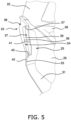
- FIG. 5 is a perspective view of the front portion of the straddled vehicle 1.
- the left front side cover 23 includes an inner cover 37, an outer cover 38, and a guide groove 39.
- the inner cover 37 is connected to the left leg shield 25.
- the inner cover 37 extends forward from the left leg shield 25.
- the outer cover 38 extends downward and rearward from the front center cover 21 as seen in the vehicle side view.
- the outer cover 38 extends from the front center cover 21 to the undercover 30.
- the outer cover 38 is arranged laterally outward of the inner cover 37.
- the guide groove 39 extends rearward and downward.
- the guide groove 39 is arranged between the outer cover 38 and the inner cover 37.
- the guide groove 39 closes an entire area between the outer cover 38 and the inner cover 37.
- an upper end 391 of the guide groove 39 is located above a lower end 501 of the seat 5.
- a lower end 392 of the guide groove 39 is located below the lower end 501 of the seat 5.
- the upper end 391 of the guide groove 39 is located above a top 401 of the front wheel 4.
- the lower end 392 of the guide groove 39 is located below the top 401 of the front wheel 4.
- the upper end 391 of the guide groove 39 is located above a lower end 281 of the center cover 28.
- the lower end 392 of the guide groove 39 is located below the lower end 281 of the center cover 28.
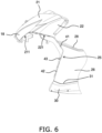
- FIG. 6 is an enlarged side view of the front portion of the straddled vehicle 1 with the left front side cover 23 removed.
- the left leg shield 25 includes an upper side edge 41, a lower side edge 42, and a step 43.
- the upper side edge 41 extends in the vertical direction of the vehicle. As seen in the vehicle side view, the upper side edge 41 has a shape that is convexly bent rearward. The upper side edge 41 is connected to the lower edge 221 of the front back cover 22.
- the lower side edge 42 is located below the upper side edge 41.
- the lower side edge 42 is located laterally outward of the upper side edge 41.
- the lower side edge 42 extends in the vertical direction of the vehicle.
- the upper side edge 41 extends from the step 43 to the left footrest surface 31. As seen in the vehicle side view, the lower side edge 42 is inclined forward and downward.
- the step 43 is located between the upper side edge 41 and the lower side edge 42.
- the step 43 extends in the vehicle width direction.
- the step 43 is provided between a lower end of the upper side edge 41 and an upper end of the lower side edge 42.
- FIG. 7 is a diagram showing a state in which the inner cover 37 is attached to the left leg shield 25.
- the inner cover 37 includes a rear edge 44, an upper edge 45, and a front edge 46.
- the rear edge 44 of the inner cover 37 has a shape that is convexly bent rearward.
- the rear edge 44 is connected to the lower side edge 42 of the left leg shield 25.
- an upper portion of the inner cover 37 is connected to the lower edge 221 of the front back cover 22.
- the rear edge 44 of the inner cover 37 has a shape corresponding to the upper side edge 41 of the left leg shield 25.
- the rear edge 44 of the inner cover 37 is connected to the upper side edge 41 of the left leg shield 25.
- the upper edge 45 of the inner cover 37 is inclined forward and downward.
- the upper edge 45 of the inner cover 37 is located below the lower edge 221 of the front back cover 22.
- the front edge 46 of the inner cover 37 is inclined forward and upward.
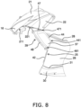
- FIG. 8 is a diagram showing a state in which the inner cover 37 and the guide groove 39 are attached to the left leg shield 25.
- the guide groove 39 is arranged in front of the inner cover 37.
- the guide groove 39 includes an upper guide portion 47 and a guide body 48.
- the guide groove 39 has a bent shape between the upper guide portion 47 and the guide body 48.
- the upper guide portion 47 is arranged above the guide body 48. As seen in the vehicle side view, the upper guide portion 47 is inclined forward and downward.
- the upper guide portion 47 has a shape corresponding to the upper edge 45 of the inner cover 37.
- the upper guide portion 47 is connected to the upper edge 45 of the inner cover 37.
- the guide body 48 is inclined rearward and downward.
- the guide body 48 has a shape corresponding to the front edge 46 of the inner cover 37.
- the guide body 48 is connected to the front edge 46 of the inner cover 37.
- the guide body 48 is longer than the upper guide portion 47 in the vertical direction of the vehicle.
- a rear end 481 of the guide body 48 is located rearward of a rear end 471 of the upper guide portion 47.
- a rear end 441 of the rear edge 44 of the inner cover 37 is located rearward of the rear end 481 of the guide body 48.
- the rear end 441 of the rear edge 44 of the inner cover 37 is located rearward of the rear end 471 of the upper guide portion 47.
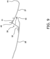
- FIG. 9 is a sectional view taken along line IX-IX in FIG. 4 .
- the guide groove 39 includes an inner side edge 51 and an outer side edge 52.
- the inner side edge 51 of the guide groove 39 has a shape that is bent rearward.
- the inner side edge 51 of the guide groove 39 is connected to an inner surface of the inner cover 37.
- the outer side edge 52 of the guide groove 39 has a shape that is bent forward.
- the outer side edge 52 of the guide groove 39 is connected to an inner surface of the outer cover 38.
- the outer cover 38 is arranged laterally outward of the guide groove 39. As illustrated in FIG. 4 , the outer cover 38 overlaps with the guide groove 39 as seen in the vehicle side view. As seen in the vehicle side view, the outer cover 38 overlaps with the entire guide groove 39. As seen in the vehicle side view, the outer cover 38 overlaps with a portion of the inner cover 37. As seen in the vehicle side view, the outer cover 38 overlaps with the front edge 46 of the inner cover 37. As seen in the vehicle side view, the outer cover 38 overlaps with the upper edge 45 of the inner cover 37.
- the outer cover 38 includes a lower rear edge 53 and an upper rear edge 54.
- the lower rear edge 53 is connected to the lower side edge 42 of the left leg shield 25. As seen in the vehicle side view, the lower rear edge 53 is inclined forward and downward.
- the upper rear edge 54 is located above the lower rear edge 53.
- the upper rear edge 54 at least partially overlaps with the inner cover 37 as seen in the vehicle side view.
- the upper rear edge 54 has a shape that is recessed forward.
- the upper rear edge 54 overlaps with the inner cover 37 as seen in the vehicle side view.
- a portion of the inner cover 37 is located rearward of the upper rear edge 54.
- a portion of the inner cover 37 is visible as seen in the vehicle side view.
- the guide groove 39 is arranged in front of the upper rear edge 54 at a distance from the upper rear edge 54.
- the guide groove 39 closes between the outer cover 38 and the inner cover 37 at a position forward of the upper rear edge 54.
- the upper rear edge 54 includes a first edge 56 and a second edge 57.
- the first edge 56 extends obliquely forward and upward from an upper end of the lower rear edge 53.
- the second edge 57 is located above the first edge 56.
- the second edge 57 extends obliquely rearward and upward from an upper end of the first edge 56.
- a rear end 571 of the second edge 57 is located forward of a rear end 561 of the first edge 56.
- the rear end 441 of the rear edge 44 of the inner cover 37 is located rearward of the rear end 571 of the second edge 57.
- the rear end 441 of the rear edge 44 of the inner cover 37 is located rearward of the rear end 561 of the first edge 56.
- the outer cover 38 includes a front edge 61 and an upper edge 62. As seen in the vehicle side view, the front edge 61 of the outer cover 38 has a curved shape so as to bulge rearward.
- the front wheel 4 is arranged in front of the front edge 61 of the outer cover 38.
- the upper edge 62 of the outer cover 38 has a shape that is convexly bent upward.
- the upper edge 62 of the outer cover 38 is connected to the lower edge 211 of the front center cover 21.
- the upper edge 62 of the outer cover 38 is connected to the lower edge 221 of the front back cover 22.
- the upper edge 62 of the outer cover 38 includes a front upper edge 63 and a rear upper edge 64.
- the front upper edge 63 is inclined rearward and upward.
- the front upper edge 63 is arranged laterally outward of the headlight 18.
- the front upper edge 63 overlaps with a portion of the headlight 18.
- the rear upper edge 64 is located behind the front upper edge 63.
- the rear upper edge 64 is inclined rearward and downward. As seen in the vehicle side view, the rear upper edge 64 is connected to the rear edge 44 of the inner cover 37.
- the outer cover 38 includes an upper side surface 66, an intermediate side surface 67, and a lower side surface 68.
- the upper side surface 66 is located above the upper end 391 of the guide groove 39.
- the intermediate side surface 67 is located below the upper end 391 of the guide groove 39.
- the intermediate side surface 67 is located above the lower end 392 of the guide groove 39.
- the lower side surface 68 is located below the lower end 392 of the guide groove 39.
- FIG. 10 is a front view of the front center cover 21 and the left and right front side covers 23 and 24.
- the intermediate side surface 67 is located laterally outward of the upper side surface 66.
- the intermediate side surface 67 is located laterally outward of the lower side surface 68.
- FIG. 11 is a cross-sectional view taken along the line XI-XI in FIG. 4 .
- a lower portion 261 of the left side cover 26 has an inwardly recessed shape at a position behind the guide groove 39.
- the lower portion 261 of the left side cover 26 is located below the lower end 392 of the guide groove 39.
- the left front side cover 23 has been described above.
- the right front side cover 24 has the same structure as the left front side cover 23 except that it is symmetrical with the left front side cover 23.
- the structure of the straddled vehicle 1 is not limited to that of the above embodiment, and may be changed.
- the number of front wheel is not limited to one, and may be more than one.
- the number of rear wheels is not limited to one, and may be more than one.
- the structure of the body frame 2 is not limited to that of the above embodiment, and may be changed.
- the shape of the down frame 12, the lower frame 13, or the rear frame 14 may be changed.
- the structures of the left and right front side covers 23 and 24 may be changed.
- the shape or arrangement of the outer cover 38 may be changed.
- the shape or arrangement of the inner cover 37 may be changed.
- the shape or arrangement of the guide groove 39 may be changed.
Landscapes
- Engineering & Computer Science (AREA)
- Mechanical Engineering (AREA)
- Automatic Cycles, And Cycles In General (AREA)
- Body Structure For Vehicles (AREA)
Claims (12)
- Véhicule à enfourcher (1), comprenant :un tube de tête (11) ;un dispositif de direction (3) supporté de manière tournante par le tube de tête (11) ;une roue avant (4) supportée de manière rotative par le dispositif de direction (3) ;un carénage central avant (21) agencé en avant du tube de tête (11) par rapport à une direction avant-arrière du véhicule et au-dessus de la roue avant (4) par rapport à une direction verticale du véhicule, et au moins un côté parmi un côté gauche et un côté droit du véhicule comprendun carénage latéral avant (23, 24) qui est connecté au carénage central avant (21) et chevauche le dispositif de direction (3) en vue latérale du véhicule ;un siège (5) agencé en arrière du tube de tête (11) par rapport à la direction avant-arrière du véhicule ;un carénage latéral arrière (26, 27) agencé en arrière du carénage latéral avant (23, 24) et qui s'étend vers l'avant par rapport à la direction avant-arrière du véhicule et depuis le dessous du siège (5) par rapport à la direction verticale du véhicule ;un bouclier de jambe (25) qui s'étend latéralement vers l'extérieur par rapport à une direction de la largeur du véhicule depuis le carénage latéral arrière (26, 27) ; etune surface de repose-pied (31, 32) connectée à une portion inférieure (261) par rapport à la direction verticale du véhicule du carénage latéral arrière (26, 27) et agencée en arrière du bouclier de jambe (25) par rapport à la direction avant-arrière du véhicule,dans lequelle bouclier de jambe (25) comprendun bord latéral supérieur (41) par rapport à la direction verticale du véhicule,un bord latéral inférieur (42) situé au-dessous, par rapport à la direction verticale du véhicule, et latéralement vers l'extérieur, par rapport à une direction de la largeur du véhicule, du bord latéral supérieur (41), etun échelon (43) situé entre le bord latéral supérieur (41) et le bord latéral inférieur (42),le carénage latéral avant (23, 24) comprend un carénage interne (37) et un carénage externe (38) par rapport à la direction de la largeur du véhicule, et une rainure de guidage (39),le carénage interne (37) est connecté au bord latéral supérieur (41) et s'étend vers l'avant depuis le bord latéral supérieur (41),le carénage externe (38) s'étend vers le bas par rapport à la direction verticale du véhicule et vers l'arrière depuis le carénage central avant (21) en vue latérale du véhicule, et est agencé latéralement vers l'extérieur du carénage interne (37) par rapport à la direction de la largeur du véhicule,le carénage externe (38) comprendun bord arrière inférieur (53) par rapport à la direction verticale du véhicule, connecté au bord latéral inférieur (42), etun bord arrière supérieur (54) qui est situé au-dessus du bord arrière inférieur (53) par rapport à la direction verticale du véhicule et qui chevauche au moins partiellement le carénage interne (37) en vue latérale du véhicule,la rainure de guidage (39) s'étend vers l'arrière par rapport à la direction avant-arrière du véhicule et vers le bas par rapport à la direction verticale du véhicule et est connectée à l'échelon (43), etla rainure de guidage (39) se ferme entre le carénage externe (38) et le carénage interne (37).
- Véhicule à enfourcher (1) selon la revendication 1, dans lequel le bord arrière supérieur (54) présente une forme qui est renfoncée vers l'avant par rapport à la direction avant-arrière du véhicule.
- Véhicule à enfourcher (1) selon la revendication 2, dans lequel une portion du carénage interne (37) est située en arrière du bord arrière supérieur (54) par rapport à la direction avant-arrière du véhicule.
- Véhicule à enfourcher (1) selon l'une quelconque des revendications 1 à 3, dans lequel la rainure de guidage (39) se ferme entre le carénage externe (38) et le carénage interne (37) à une position en avant du bord arrière supérieur (54) par rapport à la direction avant-arrière du véhicule.
- Véhicule à enfourcher (1) selon l'une quelconque des revendications 1 à 4, dans lequel le carénage externe (38) chevauche l'entièreté de la rainure de guidage (39) en vue latérale du véhicule.
- Véhicule à enfourcher (1) selon l'une quelconque des revendications 1 à 5, dans lequel le carénage latéral arrière (26, 27) présente une forme qui est renfoncée latéralement vers l'intérieur par rapport à la direction de la largeur du véhicule à une position située en arrière de la rainure de guidage (39) par rapport à la direction avant-arrière du véhicule.
- Véhicule à enfourcher (1) selon l'une quelconque des revendications 1 à 6, dans lequel une extrémité supérieure (391) de la rainure de guidage (39) est située au-dessus d'une extrémité inférieure (501) du siège (5) par rapport à la direction verticale du véhicule.
- Véhicule à enfourcher (1) selon l'une quelconque des revendications 1 à 7, dans lequel une extrémité inférieure (392) de la rainure de guidage (39) est située au-dessous de l'extrémité inférieure (501) du siège (5) par rapport à la direction verticale du véhicule.
- Véhicule à enfourcher (1) selon l'une quelconque des revendications 1 à 8, dans lequel l'extrémité inférieure (392) de la rainure de guidage (39) est située au-dessous d'un sommet (401) de la roue avant (4) par rapport à la direction verticale du véhicule.
- Véhicule à enfourcher (1) selon l'une quelconque des revendications 1 à 9, dans lequel le carénage externe (38) comprendune surface latérale supérieure (66) située au-dessus de l'extrémité supérieure (391) de la rainure de guidage (39) par rapport à la direction verticale du véhicule, etune surface latérale intermédiaire (67) située au-dessous de l'extrémité supérieure (391) de la rainure de guidage (39) et au-dessus de l'extrémité inférieure (392) de la rainure de guidage (39) par rapport à la direction verticale du véhicule, eten vue de face du véhicule, la surface latérale intermédiaire (67) est située latéralement vers l'extérieur de la surface latérale supérieure (66) par rapport à la direction de la largeur du véhicule.
- Véhicule à enfourcher (1) selon la revendication 10, dans lequel le carénage externe (38) comprend en outre une surface latérale inférieure (68) située au-dessous de l'extrémité inférieure (392) de la rainure de guidage (39) par rapport à la direction verticale du véhicule, et
en vue de face du véhicule, la surface latérale intermédiaire (67) est située latéralement vers l'extérieur de la surface latérale inférieure (68) par rapport à la direction de la largeur du véhicule. - Véhicule à enfourcher (1) selon l'une quelconque des revendications 1 à 11, dans lequel le côté gauche et le côté droit du véhicule comprennent chacunun carénage latéral avant comme carénage latéral gauche (23) et carénage latéral droit (24),un carénage latéral arrière comme carénage latéral arrière gauche (26) et carénage latéral arrière droit (27),un bouclier de jambe comme bouclier de jambe gauche (25) et bouclier de jambe droit,une surface de repose-pied comme surface de repose-pied gauche (31) et surface de repose-pied droit (32).
Applications Claiming Priority (1)
| Application Number | Priority Date | Filing Date | Title |
|---|---|---|---|
| JP2020064743A JP2021160581A (ja) | 2020-03-31 | 2020-03-31 | 鞍乗型車両 |
Publications (2)
| Publication Number | Publication Date |
|---|---|
| EP3889014A1 EP3889014A1 (fr) | 2021-10-06 |
| EP3889014B1 true EP3889014B1 (fr) | 2023-05-10 |
Family
ID=74844812
Family Applications (1)
| Application Number | Title | Priority Date | Filing Date |
|---|---|---|---|
| EP21159917.0A Active EP3889014B1 (fr) | 2020-03-31 | 2021-03-01 | Véhicule à enfourcher |
Country Status (3)
| Country | Link |
|---|---|
| EP (1) | EP3889014B1 (fr) |
| JP (1) | JP2021160581A (fr) |
| PH (1) | PH12021050139A1 (fr) |
Families Citing this family (1)
| Publication number | Priority date | Publication date | Assignee | Title |
|---|---|---|---|---|
| JP7470723B2 (ja) * | 2022-02-08 | 2024-04-18 | 本田技研工業株式会社 | 鞍乗り型車両 |
Family Cites Families (4)
| Publication number | Priority date | Publication date | Assignee | Title |
|---|---|---|---|---|
| JP3340637B2 (ja) * | 1997-01-21 | 2002-11-05 | 本田技研工業株式会社 | スクータ型自動二輪車の足載板とフロアスカートとの結合構造 |
| JP3469027B2 (ja) * | 1997-01-21 | 2003-11-25 | 本田技研工業株式会社 | スクータ型車両のエンジン冷却装置 |
| JP5912718B2 (ja) * | 2012-03-22 | 2016-04-27 | 本田技研工業株式会社 | 鞍乗り型車両の防風構造 |
| JP5990114B2 (ja) | 2013-02-28 | 2016-09-07 | 本田技研工業株式会社 | 鞍乗型車両 |
-
2020
- 2020-03-31 JP JP2020064743A patent/JP2021160581A/ja active Pending
-
2021
- 2021-03-01 EP EP21159917.0A patent/EP3889014B1/fr active Active
- 2021-03-31 PH PH12021050139A patent/PH12021050139A1/en unknown
Also Published As
| Publication number | Publication date |
|---|---|
| PH12021050139A1 (en) | 2021-11-22 |
| JP2021160581A (ja) | 2021-10-11 |
| EP3889014A1 (fr) | 2021-10-06 |
Similar Documents
| Publication | Publication Date | Title |
|---|---|---|
| JP5280430B2 (ja) | 鞍乗り型車両のインナーラック構造 | |
| EP2168850B1 (fr) | Véhicule de type à enfourcher | |
| JP6014766B2 (ja) | 自動二輪車のボディカバー構造 | |
| EP2463186B1 (fr) | Motocyclette | |
| JP7360788B2 (ja) | 鞍乗型車両のカバー構造 | |
| CN102398650B (zh) | 鞍乘型车辆的腿部遮护板结构 | |
| JP5604124B2 (ja) | 自動二輪車 | |
| EP3889014B1 (fr) | Véhicule à enfourcher | |
| JP5404319B2 (ja) | 自動二輪車 | |
| JP5806643B2 (ja) | 鞍乗り型車両の車体カバー構造 | |
| CN103183082B (zh) | 骑乘型车辆 | |
| JP5358557B2 (ja) | 鞍乗型車両 | |
| EP4112430B1 (fr) | Véhicule de type à selle | |
| JP5937460B2 (ja) | 鞍乗り型車両の携帯端末収納構造 | |
| JP5728346B2 (ja) | 車両の前部構造 | |
| JP3504098B2 (ja) | スクータ型車両の風防装置 | |
| JP2014069596A (ja) | 二輪車のハンドルカバー装置 | |
| JP6133338B2 (ja) | 自動二輪車の前部構造 | |
| JP2020066408A (ja) | 鞍乗型車両 | |
| JP2012071773A (ja) | 小型車両 | |
| JP7657250B2 (ja) | 鞍乗り型車両の車体前部構造 | |
| JP6207098B2 (ja) | 自動二輪車の車体カバー、及び、自動二輪車 | |
| JP7450773B2 (ja) | 鞍乗り型車両 | |
| JP7357026B2 (ja) | 鞍乗り型車両 | |
| JP7406623B2 (ja) | 鞍乗り型車両 |
Legal Events
| Date | Code | Title | Description |
|---|---|---|---|
| PUAI | Public reference made under article 153(3) epc to a published international application that has entered the european phase |
Free format text: ORIGINAL CODE: 0009012 |
|
| STAA | Information on the status of an ep patent application or granted ep patent |
Free format text: STATUS: REQUEST FOR EXAMINATION WAS MADE |
|
| 17P | Request for examination filed |
Effective date: 20210301 |
|
| AK | Designated contracting states |
Kind code of ref document: A1 Designated state(s): AL AT BE BG CH CY CZ DE DK EE ES FI FR GB GR HR HU IE IS IT LI LT LU LV MC MK MT NL NO PL PT RO RS SE SI SK SM TR |
|
| RBV | Designated contracting states (corrected) |
Designated state(s): AL AT BE BG CH CY CZ DE DK EE ES FI FR GB GR HR HU IE IS IT LI LT LU LV MC MK MT NL NO PL PT RO RS SE SI SK SM TR |
|
| STAA | Information on the status of an ep patent application or granted ep patent |
Free format text: STATUS: EXAMINATION IS IN PROGRESS |
|
| 17Q | First examination report despatched |
Effective date: 20220613 |
|
| GRAP | Despatch of communication of intention to grant a patent |
Free format text: ORIGINAL CODE: EPIDOSNIGR1 |
|
| STAA | Information on the status of an ep patent application or granted ep patent |
Free format text: STATUS: GRANT OF PATENT IS INTENDED |
|
| INTG | Intention to grant announced |
Effective date: 20221205 |
|
| GRAS | Grant fee paid |
Free format text: ORIGINAL CODE: EPIDOSNIGR3 |
|
| GRAA | (expected) grant |
Free format text: ORIGINAL CODE: 0009210 |
|
| STAA | Information on the status of an ep patent application or granted ep patent |
Free format text: STATUS: THE PATENT HAS BEEN GRANTED |
|
| AK | Designated contracting states |
Kind code of ref document: B1 Designated state(s): AL AT BE BG CH CY CZ DE DK EE ES FI FR GB GR HR HU IE IS IT LI LT LU LV MC MK MT NL NO PL PT RO RS SE SI SK SM TR |
|
| REG | Reference to a national code |
Ref country code: GB Ref legal event code: FG4D |
|
| REG | Reference to a national code |
Ref country code: AT Ref legal event code: REF Ref document number: 1566445 Country of ref document: AT Kind code of ref document: T Effective date: 20230515 Ref country code: CH Ref legal event code: EP |
|
| REG | Reference to a national code |
Ref country code: DE Ref legal event code: R096 Ref document number: 602021002232 Country of ref document: DE |
|
| REG | Reference to a national code |
Ref country code: IE Ref legal event code: FG4D |
|
| P01 | Opt-out of the competence of the unified patent court (upc) registered |
Effective date: 20230527 |
|
| REG | Reference to a national code |
Ref country code: LT Ref legal event code: MG9D |
|
| REG | Reference to a national code |
Ref country code: NL Ref legal event code: MP Effective date: 20230510 |
|
| REG | Reference to a national code |
Ref country code: AT Ref legal event code: MK05 Ref document number: 1566445 Country of ref document: AT Kind code of ref document: T Effective date: 20230510 |
|
| PG25 | Lapsed in a contracting state [announced via postgrant information from national office to epo] |
Ref country code: SE Free format text: LAPSE BECAUSE OF FAILURE TO SUBMIT A TRANSLATION OF THE DESCRIPTION OR TO PAY THE FEE WITHIN THE PRESCRIBED TIME-LIMIT Effective date: 20230510 Ref country code: PT Free format text: LAPSE BECAUSE OF FAILURE TO SUBMIT A TRANSLATION OF THE DESCRIPTION OR TO PAY THE FEE WITHIN THE PRESCRIBED TIME-LIMIT Effective date: 20230911 Ref country code: NO Free format text: LAPSE BECAUSE OF FAILURE TO SUBMIT A TRANSLATION OF THE DESCRIPTION OR TO PAY THE FEE WITHIN THE PRESCRIBED TIME-LIMIT Effective date: 20230810 Ref country code: NL Free format text: LAPSE BECAUSE OF FAILURE TO SUBMIT A TRANSLATION OF THE DESCRIPTION OR TO PAY THE FEE WITHIN THE PRESCRIBED TIME-LIMIT Effective date: 20230510 Ref country code: ES Free format text: LAPSE BECAUSE OF FAILURE TO SUBMIT A TRANSLATION OF THE DESCRIPTION OR TO PAY THE FEE WITHIN THE PRESCRIBED TIME-LIMIT Effective date: 20230510 Ref country code: AT Free format text: LAPSE BECAUSE OF FAILURE TO SUBMIT A TRANSLATION OF THE DESCRIPTION OR TO PAY THE FEE WITHIN THE PRESCRIBED TIME-LIMIT Effective date: 20230510 |
|
| PG25 | Lapsed in a contracting state [announced via postgrant information from national office to epo] |
Ref country code: RS Free format text: LAPSE BECAUSE OF FAILURE TO SUBMIT A TRANSLATION OF THE DESCRIPTION OR TO PAY THE FEE WITHIN THE PRESCRIBED TIME-LIMIT Effective date: 20230510 Ref country code: PL Free format text: LAPSE BECAUSE OF FAILURE TO SUBMIT A TRANSLATION OF THE DESCRIPTION OR TO PAY THE FEE WITHIN THE PRESCRIBED TIME-LIMIT Effective date: 20230510 Ref country code: LV Free format text: LAPSE BECAUSE OF FAILURE TO SUBMIT A TRANSLATION OF THE DESCRIPTION OR TO PAY THE FEE WITHIN THE PRESCRIBED TIME-LIMIT Effective date: 20230510 Ref country code: LT Free format text: LAPSE BECAUSE OF FAILURE TO SUBMIT A TRANSLATION OF THE DESCRIPTION OR TO PAY THE FEE WITHIN THE PRESCRIBED TIME-LIMIT Effective date: 20230510 Ref country code: IS Free format text: LAPSE BECAUSE OF FAILURE TO SUBMIT A TRANSLATION OF THE DESCRIPTION OR TO PAY THE FEE WITHIN THE PRESCRIBED TIME-LIMIT Effective date: 20230910 Ref country code: HR Free format text: LAPSE BECAUSE OF FAILURE TO SUBMIT A TRANSLATION OF THE DESCRIPTION OR TO PAY THE FEE WITHIN THE PRESCRIBED TIME-LIMIT Effective date: 20230510 Ref country code: GR Free format text: LAPSE BECAUSE OF FAILURE TO SUBMIT A TRANSLATION OF THE DESCRIPTION OR TO PAY THE FEE WITHIN THE PRESCRIBED TIME-LIMIT Effective date: 20230811 |
|
| PG25 | Lapsed in a contracting state [announced via postgrant information from national office to epo] |
Ref country code: FI Free format text: LAPSE BECAUSE OF FAILURE TO SUBMIT A TRANSLATION OF THE DESCRIPTION OR TO PAY THE FEE WITHIN THE PRESCRIBED TIME-LIMIT Effective date: 20230510 |
|
| PG25 | Lapsed in a contracting state [announced via postgrant information from national office to epo] |
Ref country code: SK Free format text: LAPSE BECAUSE OF FAILURE TO SUBMIT A TRANSLATION OF THE DESCRIPTION OR TO PAY THE FEE WITHIN THE PRESCRIBED TIME-LIMIT Effective date: 20230510 |
|
| PG25 | Lapsed in a contracting state [announced via postgrant information from national office to epo] |
Ref country code: SM Free format text: LAPSE BECAUSE OF FAILURE TO SUBMIT A TRANSLATION OF THE DESCRIPTION OR TO PAY THE FEE WITHIN THE PRESCRIBED TIME-LIMIT Effective date: 20230510 Ref country code: SK Free format text: LAPSE BECAUSE OF FAILURE TO SUBMIT A TRANSLATION OF THE DESCRIPTION OR TO PAY THE FEE WITHIN THE PRESCRIBED TIME-LIMIT Effective date: 20230510 Ref country code: RO Free format text: LAPSE BECAUSE OF FAILURE TO SUBMIT A TRANSLATION OF THE DESCRIPTION OR TO PAY THE FEE WITHIN THE PRESCRIBED TIME-LIMIT Effective date: 20230510 Ref country code: EE Free format text: LAPSE BECAUSE OF FAILURE TO SUBMIT A TRANSLATION OF THE DESCRIPTION OR TO PAY THE FEE WITHIN THE PRESCRIBED TIME-LIMIT Effective date: 20230510 Ref country code: DK Free format text: LAPSE BECAUSE OF FAILURE TO SUBMIT A TRANSLATION OF THE DESCRIPTION OR TO PAY THE FEE WITHIN THE PRESCRIBED TIME-LIMIT Effective date: 20230510 Ref country code: CZ Free format text: LAPSE BECAUSE OF FAILURE TO SUBMIT A TRANSLATION OF THE DESCRIPTION OR TO PAY THE FEE WITHIN THE PRESCRIBED TIME-LIMIT Effective date: 20230510 |
|
| REG | Reference to a national code |
Ref country code: DE Ref legal event code: R097 Ref document number: 602021002232 Country of ref document: DE |
|
| PLBE | No opposition filed within time limit |
Free format text: ORIGINAL CODE: 0009261 |
|
| STAA | Information on the status of an ep patent application or granted ep patent |
Free format text: STATUS: NO OPPOSITION FILED WITHIN TIME LIMIT |
|
| 26N | No opposition filed |
Effective date: 20240213 |
|
| PG25 | Lapsed in a contracting state [announced via postgrant information from national office to epo] |
Ref country code: SI Free format text: LAPSE BECAUSE OF FAILURE TO SUBMIT A TRANSLATION OF THE DESCRIPTION OR TO PAY THE FEE WITHIN THE PRESCRIBED TIME-LIMIT Effective date: 20230510 |
|
| PG25 | Lapsed in a contracting state [announced via postgrant information from national office to epo] |
Ref country code: SI Free format text: LAPSE BECAUSE OF FAILURE TO SUBMIT A TRANSLATION OF THE DESCRIPTION OR TO PAY THE FEE WITHIN THE PRESCRIBED TIME-LIMIT Effective date: 20230510 |
|
| REG | Reference to a national code |
Ref country code: CH Ref legal event code: PL |
|
| PG25 | Lapsed in a contracting state [announced via postgrant information from national office to epo] |
Ref country code: BG Free format text: LAPSE BECAUSE OF FAILURE TO SUBMIT A TRANSLATION OF THE DESCRIPTION OR TO PAY THE FEE WITHIN THE PRESCRIBED TIME-LIMIT Effective date: 20230510 |
|
| PG25 | Lapsed in a contracting state [announced via postgrant information from national office to epo] |
Ref country code: LU Free format text: LAPSE BECAUSE OF NON-PAYMENT OF DUE FEES Effective date: 20240301 |
|
| PG25 | Lapsed in a contracting state [announced via postgrant information from national office to epo] |
Ref country code: MC Free format text: LAPSE BECAUSE OF FAILURE TO SUBMIT A TRANSLATION OF THE DESCRIPTION OR TO PAY THE FEE WITHIN THE PRESCRIBED TIME-LIMIT Effective date: 20230510 |
|
| PG25 | Lapsed in a contracting state [announced via postgrant information from national office to epo] |
Ref country code: MC Free format text: LAPSE BECAUSE OF FAILURE TO SUBMIT A TRANSLATION OF THE DESCRIPTION OR TO PAY THE FEE WITHIN THE PRESCRIBED TIME-LIMIT Effective date: 20230510 Ref country code: LU Free format text: LAPSE BECAUSE OF NON-PAYMENT OF DUE FEES Effective date: 20240301 Ref country code: BG Free format text: LAPSE BECAUSE OF FAILURE TO SUBMIT A TRANSLATION OF THE DESCRIPTION OR TO PAY THE FEE WITHIN THE PRESCRIBED TIME-LIMIT Effective date: 20230510 |
|
| REG | Reference to a national code |
Ref country code: BE Ref legal event code: MM Effective date: 20240331 |
|
| PG25 | Lapsed in a contracting state [announced via postgrant information from national office to epo] |
Ref country code: BE Free format text: LAPSE BECAUSE OF NON-PAYMENT OF DUE FEES Effective date: 20240331 |
|
| PG25 | Lapsed in a contracting state [announced via postgrant information from national office to epo] |
Ref country code: IE Free format text: LAPSE BECAUSE OF NON-PAYMENT OF DUE FEES Effective date: 20240301 |
|
| PG25 | Lapsed in a contracting state [announced via postgrant information from national office to epo] |
Ref country code: IE Free format text: LAPSE BECAUSE OF NON-PAYMENT OF DUE FEES Effective date: 20240301 Ref country code: BE Free format text: LAPSE BECAUSE OF NON-PAYMENT OF DUE FEES Effective date: 20240331 Ref country code: CH Free format text: LAPSE BECAUSE OF NON-PAYMENT OF DUE FEES Effective date: 20240331 |
|
| PG25 | Lapsed in a contracting state [announced via postgrant information from national office to epo] |
Ref country code: CY Free format text: LAPSE BECAUSE OF FAILURE TO SUBMIT A TRANSLATION OF THE DESCRIPTION OR TO PAY THE FEE WITHIN THE PRESCRIBED TIME-LIMIT; INVALID AB INITIO Effective date: 20210301 |
|
| PG25 | Lapsed in a contracting state [announced via postgrant information from national office to epo] |
Ref country code: HU Free format text: LAPSE BECAUSE OF FAILURE TO SUBMIT A TRANSLATION OF THE DESCRIPTION OR TO PAY THE FEE WITHIN THE PRESCRIBED TIME-LIMIT; INVALID AB INITIO Effective date: 20210301 |
|
| GBPC | Gb: european patent ceased through non-payment of renewal fee |
Effective date: 20250301 |
|
| PG25 | Lapsed in a contracting state [announced via postgrant information from national office to epo] |
Ref country code: TR Free format text: LAPSE BECAUSE OF FAILURE TO SUBMIT A TRANSLATION OF THE DESCRIPTION OR TO PAY THE FEE WITHIN THE PRESCRIBED TIME-LIMIT Effective date: 20230510 |
|
| PG25 | Lapsed in a contracting state [announced via postgrant information from national office to epo] |
Ref country code: GB Free format text: LAPSE BECAUSE OF NON-PAYMENT OF DUE FEES Effective date: 20250301 |
|
| PGFP | Annual fee paid to national office [announced via postgrant information from national office to epo] |
Ref country code: DE Payment date: 20260319 Year of fee payment: 6 |
|
| PGFP | Annual fee paid to national office [announced via postgrant information from national office to epo] |
Ref country code: IT Payment date: 20260324 Year of fee payment: 6 |
|
| PGFP | Annual fee paid to national office [announced via postgrant information from national office to epo] |
Ref country code: FR Payment date: 20260323 Year of fee payment: 6 |