EP3889087A1 - Dispositif de collecte et de transport destiné à la collecte et au transport de produits imprimés en forme de feuilles - Google Patents
Dispositif de collecte et de transport destiné à la collecte et au transport de produits imprimés en forme de feuilles Download PDFInfo
- Publication number
- EP3889087A1 EP3889087A1 EP21160727.0A EP21160727A EP3889087A1 EP 3889087 A1 EP3889087 A1 EP 3889087A1 EP 21160727 A EP21160727 A EP 21160727A EP 3889087 A1 EP3889087 A1 EP 3889087A1
- Authority
- EP
- European Patent Office
- Prior art keywords
- printed products
- collecting
- further conveying
- conveying
- adjustable
- Prior art date
- Legal status (The legal status is an assumption and is not a legal conclusion. Google has not performed a legal analysis and makes no representation as to the accuracy of the status listed.)
- Withdrawn
Links
- 239000000123 paper Substances 0.000 claims abstract description 10
- 230000006978 adaptation Effects 0.000 claims description 4
- 239000000047 product Substances 0.000 description 96
- 238000011144 upstream manufacturing Methods 0.000 description 14
- 238000000034 method Methods 0.000 description 5
- 238000006243 chemical reaction Methods 0.000 description 4
- 238000004519 manufacturing process Methods 0.000 description 4
- 230000000694 effects Effects 0.000 description 3
- 230000010354 integration Effects 0.000 description 3
- 238000003860 storage Methods 0.000 description 2
- 244000287680 Garcinia dulcis Species 0.000 description 1
- 229910000831 Steel Inorganic materials 0.000 description 1
- 230000001133 acceleration Effects 0.000 description 1
- 230000009286 beneficial effect Effects 0.000 description 1
- 239000011230 binding agent Substances 0.000 description 1
- 230000015572 biosynthetic process Effects 0.000 description 1
- 239000007795 chemical reaction product Substances 0.000 description 1
- 238000005520 cutting process Methods 0.000 description 1
- 230000001419 dependent effect Effects 0.000 description 1
- 238000011161 development Methods 0.000 description 1
- 230000018109 developmental process Effects 0.000 description 1
- 238000006073 displacement reaction Methods 0.000 description 1
- 238000012432 intermediate storage Methods 0.000 description 1
- 230000000717 retained effect Effects 0.000 description 1
- 239000010959 steel Substances 0.000 description 1
Images



Classifications
-
- B—PERFORMING OPERATIONS; TRANSPORTING
- B65—CONVEYING; PACKING; STORING; HANDLING THIN OR FILAMENTARY MATERIAL
- B65H—HANDLING THIN OR FILAMENTARY MATERIAL, e.g. SHEETS, WEBS, CABLES
- B65H31/00—Pile receivers
- B65H31/20—Pile receivers adjustable for different article sizes
-
- B—PERFORMING OPERATIONS; TRANSPORTING
- B65—CONVEYING; PACKING; STORING; HANDLING THIN OR FILAMENTARY MATERIAL
- B65H—HANDLING THIN OR FILAMENTARY MATERIAL, e.g. SHEETS, WEBS, CABLES
- B65H31/00—Pile receivers
- B65H31/30—Arrangements for removing completed piles
- B65H31/3054—Arrangements for removing completed piles by moving the surface supporting the lowermost article of the pile, e.g. by using belts or rollers
-
- B—PERFORMING OPERATIONS; TRANSPORTING
- B65—CONVEYING; PACKING; STORING; HANDLING THIN OR FILAMENTARY MATERIAL
- B65H—HANDLING THIN OR FILAMENTARY MATERIAL, e.g. SHEETS, WEBS, CABLES
- B65H31/00—Pile receivers
- B65H31/30—Arrangements for removing completed piles
- B65H31/3081—Arrangements for removing completed piles by acting on edge of the pile for moving it along a surface, e.g. by pushing
-
- B—PERFORMING OPERATIONS; TRANSPORTING
- B65—CONVEYING; PACKING; STORING; HANDLING THIN OR FILAMENTARY MATERIAL
- B65H—HANDLING THIN OR FILAMENTARY MATERIAL, e.g. SHEETS, WEBS, CABLES
- B65H31/00—Pile receivers
- B65H31/34—Apparatus for squaring-up piled articles
- B65H31/38—Apparatus for vibrating or knocking the pile during piling
-
- B—PERFORMING OPERATIONS; TRANSPORTING
- B65—CONVEYING; PACKING; STORING; HANDLING THIN OR FILAMENTARY MATERIAL
- B65H—HANDLING THIN OR FILAMENTARY MATERIAL, e.g. SHEETS, WEBS, CABLES
- B65H2301/00—Handling processes for sheets or webs
- B65H2301/30—Orientation, displacement, position of the handled material
- B65H2301/34—Modifying, selecting, changing direction of displacement
- B65H2301/341—Modifying, selecting, changing direction of displacement without change of plane of displacement
- B65H2301/3411—Right angle arrangement, i.e. 90 degrees
- B65H2301/34112—Right angle arrangement, i.e. 90 degrees changing leading edge
-
- B—PERFORMING OPERATIONS; TRANSPORTING
- B65—CONVEYING; PACKING; STORING; HANDLING THIN OR FILAMENTARY MATERIAL
- B65H—HANDLING THIN OR FILAMENTARY MATERIAL, e.g. SHEETS, WEBS, CABLES
- B65H2301/00—Handling processes for sheets or webs
- B65H2301/40—Type of handling process
- B65H2301/44—Moving, forwarding, guiding material
- B65H2301/447—Moving, forwarding, guiding material transferring material between transport devices
- B65H2301/4473—Belts, endless moving elements on which the material is in surface contact
-
- B—PERFORMING OPERATIONS; TRANSPORTING
- B65—CONVEYING; PACKING; STORING; HANDLING THIN OR FILAMENTARY MATERIAL
- B65H—HANDLING THIN OR FILAMENTARY MATERIAL, e.g. SHEETS, WEBS, CABLES
- B65H2404/00—Parts for transporting or guiding the handled material
- B65H2404/10—Rollers
- B65H2404/15—Roller assembly, particular roller arrangement
- B65H2404/152—Arrangement of roller on a movable frame
- B65H2404/1523—Arrangement of roller on a movable frame moving in parallel to its axis
-
- B—PERFORMING OPERATIONS; TRANSPORTING
- B65—CONVEYING; PACKING; STORING; HANDLING THIN OR FILAMENTARY MATERIAL
- B65H—HANDLING THIN OR FILAMENTARY MATERIAL, e.g. SHEETS, WEBS, CABLES
- B65H2404/00—Parts for transporting or guiding the handled material
- B65H2404/10—Rollers
- B65H2404/15—Roller assembly, particular roller arrangement
- B65H2404/154—Rollers conveyor
- B65H2404/1544—Rollers conveyor on a movable frame
-
- B—PERFORMING OPERATIONS; TRANSPORTING
- B65—CONVEYING; PACKING; STORING; HANDLING THIN OR FILAMENTARY MATERIAL
- B65H—HANDLING THIN OR FILAMENTARY MATERIAL, e.g. SHEETS, WEBS, CABLES
- B65H2404/00—Parts for transporting or guiding the handled material
- B65H2404/20—Belts
- B65H2404/25—Driving or guiding arrangements
- B65H2404/254—Arrangement for varying the guiding or transport length
-
- B—PERFORMING OPERATIONS; TRANSPORTING
- B65—CONVEYING; PACKING; STORING; HANDLING THIN OR FILAMENTARY MATERIAL
- B65H—HANDLING THIN OR FILAMENTARY MATERIAL, e.g. SHEETS, WEBS, CABLES
- B65H2404/00—Parts for transporting or guiding the handled material
- B65H2404/20—Belts
- B65H2404/26—Particular arrangement of belt, or belts
- B65H2404/264—Arrangement of side-by-side belts
-
- B—PERFORMING OPERATIONS; TRANSPORTING
- B65—CONVEYING; PACKING; STORING; HANDLING THIN OR FILAMENTARY MATERIAL
- B65H—HANDLING THIN OR FILAMENTARY MATERIAL, e.g. SHEETS, WEBS, CABLES
- B65H2404/00—Parts for transporting or guiding the handled material
- B65H2404/20—Belts
- B65H2404/26—Particular arrangement of belt, or belts
- B65H2404/264—Arrangement of side-by-side belts
- B65H2404/2641—Arrangement of side-by-side belts on movable frame
-
- B—PERFORMING OPERATIONS; TRANSPORTING
- B65—CONVEYING; PACKING; STORING; HANDLING THIN OR FILAMENTARY MATERIAL
- B65H—HANDLING THIN OR FILAMENTARY MATERIAL, e.g. SHEETS, WEBS, CABLES
- B65H2404/00—Parts for transporting or guiding the handled material
- B65H2404/20—Belts
- B65H2404/26—Particular arrangement of belt, or belts
- B65H2404/269—Particular arrangement of belt, or belts other arrangements
- B65H2404/2693—Arrangement of belts on movable frame
-
- B—PERFORMING OPERATIONS; TRANSPORTING
- B65—CONVEYING; PACKING; STORING; HANDLING THIN OR FILAMENTARY MATERIAL
- B65H—HANDLING THIN OR FILAMENTARY MATERIAL, e.g. SHEETS, WEBS, CABLES
- B65H2405/00—Parts for holding the handled material
- B65H2405/10—Cassettes, holders, bins, decks, trays, supports or magazines for sheets stacked substantially horizontally
- B65H2405/11—Parts and details thereof
- B65H2405/111—Bottom
- B65H2405/1116—Bottom with means for changing geometry
- B65H2405/11164—Rear portion extensible in parallel to transport direction
-
- B—PERFORMING OPERATIONS; TRANSPORTING
- B65—CONVEYING; PACKING; STORING; HANDLING THIN OR FILAMENTARY MATERIAL
- B65H—HANDLING THIN OR FILAMENTARY MATERIAL, e.g. SHEETS, WEBS, CABLES
- B65H2405/00—Parts for holding the handled material
- B65H2405/10—Cassettes, holders, bins, decks, trays, supports or magazines for sheets stacked substantially horizontally
- B65H2405/11—Parts and details thereof
- B65H2405/111—Bottom
- B65H2405/1117—Bottom pivotable, e.g. around an axis perpendicular to transport direction, e.g. arranged at rear side of sheet support
- B65H2405/11171—Bottom pivotable, e.g. around an axis perpendicular to transport direction, e.g. arranged at rear side of sheet support around an axis parallel to transport direction
-
- B—PERFORMING OPERATIONS; TRANSPORTING
- B65—CONVEYING; PACKING; STORING; HANDLING THIN OR FILAMENTARY MATERIAL
- B65H—HANDLING THIN OR FILAMENTARY MATERIAL, e.g. SHEETS, WEBS, CABLES
- B65H2701/00—Handled material; Storage means
- B65H2701/10—Handled articles or webs
- B65H2701/18—Form of handled article or web
- B65H2701/182—Piled package
Definitions
- the invention relates to a collecting and conveying device for collecting and conveying sheet-shaped printed products according to claim 1
- printed products are manufactured with a wide variety of requirements and formats.
- printed paper is stacked, aligned, glued, stapled and / or also folded or creased.
- the invention is based on the object of lowering the operating costs for processing printed products.
- the invention relates to a collecting and conveying device for collecting and conveying sheet-shaped printed products, preferably unstapled stacks of sheet-shaped printed products, such as. B. paper, in particular flat sheets, cardboard or the like, to a downstream conveyor line and / or to a downstream device further processing the printed products, with a housing and with conveying means for feeding the printed products into the collecting and further conveying device and with further conveying means for their further conveyance .
- This collecting and further conveying device is characterized in that the further conveying direction of the further conveying means is directed transversely to the conveying direction of the feeding means for the printed products to be collected and conveyed.
- a separate floor space for a collecting and further conveying device constructed in this way is not required in a space-saving and thus cost-saving manner. It can be placed directly in the line of a collecting line, e.g. a stapling machine, integrated, if necessary placed on top of it. Instead, for example, a supply of printed products to be processed can be positioned on the production area that is freely available next to the collecting line. For example in the form of a tower shelf, possibly with a delivery unit for delivering loose sheets or flat sheets, in particular in the form of a stack of such loose sheets or flat sheets, to the collecting and further conveying device.
- the collecting and further conveying device for collecting and further conveying sheet-shaped printed products is in particular a deflection unit which changes the conveying direction of an unstapled stack of sheets by preferably 90 ° in the horizontal plane, with the orientation of the stack of sheets remaining the same.
- variable-length adjustable conveyor path for adaptation to different formats of printed products to be collected and conveyed on can be provided for the feed means.
- the conveying length and / or the transfer line from the supply conveying means to the further conveying means can be adapted to different formats and lengths of printed products to be collected and further conveyed.
- an adjustment of their distance to the further conveying means is possible, which can be implemented, for example, in the form of a so-called cross belt comprising a transport belt, as described in more detail below. The distance in turn depends, among other things, on the format of the printed products to be processed.
- the formats of the collecting and further conveying device for collecting and further conveying sheet-shaped printed products can, for example, be between credit card format and A3.
- the conveying-side end of the variable-length conveying path is designed to be adjustable in position, in particular with respect to a longitudinal axis running through the further conveying means in the further conveying direction.
- the change in length of the conveyor line can take place directly at the point of transfer and, if necessary, an adaptation to different properties of different printed products can be made possible.
- Another advantage is that the position of the inlet or takeover area of the variable-length adjustable conveyor line can remain unchanged. This means that no time-consuming and therefore costly retooling is required when changing formats in this area.
- a variable-position, preferably vibratable stop can be provided for the printed products to be collected and conveyed on, in particular to adapt to different formats of such printed products and / or to align printed products on top of one another.
- the jarring of the stop can be generated, for example, by appropriately controlled actuators, e.g. to create a stack with clean edges from the printed products to be collected and conveyed on.
- an inlet unit is provided at the beginning, which takes over the stack from the outside from the direction of the haul-off tower and conveys it to a stop that can be adjusted depending on the format.
- a transverse conveyor for example a transverse belt consisting of two parallel transport belts.
- the distance between the two transport belts can be adjusted depending on the format. In between there is a grille so that nothing falls through.
- the cross belt During the entry into the deflection unit, the cross belt must be passed over by the stack of printed products to be fed in, without the loose stack of sheets getting stuck between the transport belts of the cross belt or on the pull grate.
- a so-called bridge slide It supports the incoming loose stack so that it does not fall between the crossbelt belts on the pull grate underneath, and pulls back before the crossbelt lifts the stack out.
- the side of the cross belt that is remote from the feed rises, lifting the stack out of the way and starting to transport it in the direction of further processing (downstream).
- the transverse belt is lowered again, and a further stack can now be fed into the area of the infeed belt while it is being transported towards the downstream device, e.g. the creasing and folding unit , which was "occupied" shortly before.
- the cross belt then conveys the stack further, e.g. B. in the creasing-folding unit, the creasing must be done exactly at right angles to the inlet edge, which is controlled by the fact that the two bands of the transverse belt can run at different speeds.
- the infeed belt (which comes from the take-off tower) must reach exactly to the infeed, generally speaking to the first or front transport belt of the cross belt, but this is adjustable, the length of the infeed belt must also be adjustable. This is because the position of the start of the infeed conveyor is fixed (invariable) in relation to the housing of the collecting and further conveying device, so that the same takeover or transfer position can always be ensured from the outside in relation to a feed device to be positioned upstream.
- Such a transfer position to be docked to the takeover position of the collecting and further conveying device can be implemented, for example, in the form of the end of an inclined elevator that feeds the printed products removed from the haul-off tower and assembled into a loose, unstapled stack.
- the transport direction is preferably changed by 90 °. So that all sheets or sheets are exactly on top of each other, the stop for the stack is positioned by means of a stopper cylinder.
- the two cross belts are driven by servomotors. As a result, they can be switched from one drive direction to the opposite direction and back again in very quick succession.
- This can be used to repeatedly "push” a stack of sheets fed and deposited thereon against a stop surface that can be positioned according to the format to be conveyed, so that the individual sheets slide together to form a stack with clean edges.
- So-called stopper cylinders are provided for positioning the stop surface in accordance with the format to be conveyed. Accordingly, so-called side stops can shake the stack on its other two sides. This means that the stack of loose, unstapled printed products to be fed in and on can be jogged together from the front and back as well as from the left and right.
- two drives in particular servo drives, are provided for the further conveying means, which drive the conveyor belts of the further conveying device on which the further conveying devices Printed products are conveyed further, each drive separately from one another in the further conveying direction.
- the further conveying means act on the printed products to be further conveyed in their left and right edge areas, in particular by means of conveyor rollers and / or conveyor belts, preferably from the underside of the printed products and in particular by means of cams provided on the conveyor belts Support of the stack, viewed in the conveying direction, from the rear.
- cams can protrude outward from the conveying surface of the respective conveyor belt, that is to say in the case of a circumferential belt upwards on the upper side and downward on the underside, in order to each form a so-called driver for the stack of sheets to be conveyed.
- the two drives of the further conveying means for aligning the printed products to be conveyed further can be designed to be controllable at least temporarily at different speeds and / or with different conveying directions.
- the stacks of printed products to be conveyed on can be delivered to a central conveyor line of a stapling device, e.g. to prepare a folding process preceding a stapling process, in particular a so-called creasing process. For this it is very important that the stacks are precisely aligned and fed with clean edges.
- the distance between the conveyor rollers and / or conveyor belts can be adjustable for setting the conveying width for the printed products to be conveyed on.
- so-called side stops can also be adjusted to adjust the conveyor width.
- the distance between the transverse belts should be able to follow this adjustment within a certain, relatively large framework in order, on the one hand, to guarantee the effectiveness of the alignment of the front edge over the two transport belts and, on the other hand, to avoid a stack jamming in the side stops.
- a support unit for the printed products to be collected and further conveyed can be arranged between the conveyor rollers and / or the conveyor belts, in particular a support unit that is preferably automatically adjustable in width in relation to the further conveying direction.
- the sides of the support unit facing the conveyor rollers and / or conveyor belts are preferably connected to them, so that when the distance is adjusted, the width of the support unit is also adjusted at the same time.
- the support unit can be designed as a support grille, in particular as a variable-width adjustable element, e.g. in the form of several elongated, flat, in particular upright or perpendicular elements, arranged side by side and connected at changing distances, comparable for example to steel rulers.
- the connections between the individual elements can, for example, alternate between the center and the outside. In this way, a good "accordion effect" can be achieved in terms of width, while at the same time providing high stability for supporting the printed products to be conveyed further and also low resistance in the further conveying direction.
- the support unit can be variably adjustable in position, preferably adjustable in height in the further conveying direction, in particular tiltable, preferably together with the conveyor rollers and / or conveyor belts.
- the entire cross belt, including the vibrator can be rotatably mounted around the drive shaft and can raise its upstream end so far that it protrudes beyond the infeed belt and thus lifts the stack of printed products to be fed and further conveyed that has come to a standstill on it, so that the cross transport can be initiated without the pile of loose sheets getting stuck on the infeed conveyor.
- the second (subsequent) stack slides on the conveying means for feeding the printed products into the collecting and further conveying device (the infeed) longitudinally above the first (previous) stack on the further conveying means (the transverse belt).
- the feed means (the infeed lengthways) are extremely narrow and cannot be adjusted in width.
- the stack entering from the front is only moved to its, in relation to the main conveying direction, which corresponds to the onward conveying direction of the Collecting and further conveying device matches, held upstream side in the inlet lengthways.
- the entire cross belt can tilt, including the jogger and stopper cylinder and the pull grate (it rotates a few degrees around the downstream drive shaft), but only for a short time so that the stack does not get stuck on the infeed belt.
- it lies horizontally in the rest position and at the level below the (always horizontal) infeed conveyor.
- the axis of the downstream (driven) deflection roller stops, and the upstream deflection roller (still behind the cross belt) is raised so far that it is above the level of the infeed conveyor and thus lifts the stack on the infeed conveyor.
- the upstream side of the transverse belt quickly lowers again as soon as the infeed belt is free.
- the second (incoming) stack is higher than the first (running out across it).
- the first stack runs on the infeed belt (transverse to the main conveying direction of the saddle stitcher) up to the rear stop, is then lifted by the cross belt (more precisely, from its upstream side), then the cross belt begins a movement downstream to the stopper cylinders, that is, to the vibrating station (the stack now moves diagonally downwards), and as soon as the upstream edge of the stack now lying on the transverse belt has left the infeed belt, the transverse belt is lowered again. Then the first stack (on the transverse belt after it has been lowered) is lower than the second one that now follows on the infeed belt, the downstream edge of which can slide over the first (previous one).
- leading edge of a stack can advantageously be aligned on the transverse belt with two servomotors.
- the collecting and further conveying device for collecting and further conveying sheet-shaped printed products it can be arranged in a height-adjustable manner in the housing, e.g. B. to make room for another desired unit to be arranged at this point for processing and / or conveying printed products.
- a possible structure for such a repositioning can be, for example, a spindle drive.
- spindle drives can be adjusted comparatively quickly and precisely, e.g. by means of a servo drive, and otherwise do not require any energy to reliably hold the set position. They can also take heavy loads.
- Such a unit for processing and / or conveying printed products can be, for example, a pass-through device for passing through and outputting printed products.
- printed products can also be fed from further locations arranged in a straight line upstream of the housing to the locations arranged downstream of the housing of the collecting and further conveying device for collecting and further conveying sheet-shaped printed products.
- This pass-through device can also be arranged in the housing for this purpose and can be positioned so that it outputs printed products to be passed through preferably to the same output point as the collecting and further conveying device for collecting and further conveying sheet-shaped printed products.
- the pass-through device for the pass-through and output of printed products can also be arranged in a height-adjustable manner in the housing.
- a spindle drive Preferably also by means of a spindle drive.
- that unit i.e. the collecting and further conveying device for collecting and further conveying sheet-shaped printed products or the transfer device, can be positioned at the position in the housing that is intended for the output of the relevant printed products.
- the collecting and further conveying device for collecting and further conveying sheet-shaped printed products or deflecting unit must also be fed.
- a collecting chain for example a folding machine (for individual folded sheets or single sheets) and transversely to the collecting direction, for example a haul-off tower for loose stacks or single sheets can be connected.
- sheets, folded sheets or stacks of sheets can be fed in by means of the deflecting unit which can be integrated into the plane of the collective flow and removed from it again - with unchanged sheet orientation.
- the deflection unit thus enables cross-feeding of printed products, e.g. B. from a take-off tower, because this is designed to feed transversely, so from the side to the chain transport direction, sheet stacks in the further processing machine. And for this, the transport direction of the sheets and / or stacks must be deflected, but not their alignment.
- the deflecting unit would be in the way of this upstream device, in order to transfer printed products on the direct path downstream, for example to a arranged there device, such as a creasing-folding unit to be able to promote. Therefore, the above-mentioned structures are provided for such repositioning, such as raising or lowering, for example spindle drives.
- a transfer table to be positioned by the upstream device, such as a folding machine, a Folded sheet or from a roll cutter or from a large format feeder to transfer a single sheet to the creasing-folding unit. If printed products from the tower are then to be processed again, the repositioning of the collecting and further conveying device just described for collecting and further conveying sheet-shaped printed products or deflecting device and, for example, transfer table is carried out in reverse order.
- both the 90 ° deflection unit and the transfer table arranged underneath can be arranged in an upper frame (stage) of the housing, which can be adjusted in height relative to a base frame by means of four spindle drives, so that either the deflection unit or the transfer table is on the height of the downstream part of the paper converting machine (preferably a crease-crease unit).
- the 90 ° deflection unit and the transfer table can preferably move up and down at the same time. This means that only one adjustment process is necessary.
- the lower position is selected for the deflection unit and the upper position for the transfer table, but it could also work the other way around.
- the transfer table is much flatter, so it is at the bottom. But because the transfer table is installed very flat (i.e. cramped) and because in practice you have to have access to it, e.g. because you have to clear a paper jam, the deflection unit above is preferably installed in an upper platform, i.e. in a frame opposite the one the stage can be raised again. Then the transfer table gets air above it and the operator has access to it.
- the collecting and further conveying device for collecting and further conveying sheet-shaped printed products is designed to be height-adjustable in relation to the transfer device for transferring and dispensing printed products in the housing and / or that the transfer device for transferring and dispensing printed products is opposite the collecting and further conveying device for collecting and further conveying sheet-shaped printed products in the housing is designed to be height-adjustable.
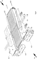
- the Figure 1 a collecting and conveying device 1 for collecting and conveying sheet-shaped printed products 5.
- the printed products are preferably in the form of unstapled stacks of sheet-shaped printed products, such as. B. paper, especially flat sheets, cardboard or the like. These are conveyed to a downstream conveyor line and / or to a device which processes the printed products further downstream.
- These unstapled stacks of sheet-shaped printed products can originate, for example, from an upstream intermediate store and be composed of, in particular, separately stored, different individual sheets.
- This Intermediate storage can be designed, for example, in a so-called tower (tower storage) with a large number of individual, preferably one above the other, partial storage (compartments).
- Loose sheets to be joined together to form a booklet or brochure can be temporarily stored therein, a set of sheets to be joined can be removed per machine cycle, combined into a stack and fed to the collecting and further conveying device 1.
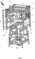
- the collecting and further conveying device 1 is in a housing 2 (see Fig. Fig. 6 ) and has feed means 3 for feeding the printed products 5 into the collecting and further conveying device 1 and further conveying means 4 for their further conveyance.
- the further conveying direction 4.1 of the further conveying means 4 is directed transversely to the conveying direction 3.1 of the feeding means 3 for the printed products 5 to be collected and conveyed.
- variable length adjustable conveying path 3.2 is provided for adapting to different formats of printed products 5 to be collected and conveyed further (e.g. from credit card size to A3).
- the length variability of the conveyor line 3.2 can be achieved by one or more, e.g. B. two deflected conveyor belts 3.4 are effected, the distance between two deflection rollers 3.5, 3.6 at the opposite ends of the conveyor line 3.2 is variable, in that at least the deflection roller 3.5 closer to the further conveying means 4 is displaceable.
- a telescopic holder can be provided between the two end pulleys 3.5, 3.6.
- the roller 3.5 must give way to the belt 4.3 closely (cross belt becomes wider) or follow (cross belt becomes narrower), i.e. it must be adjustable.
- the deflection rollers 3.7, 3.8, 3.9, 3.10 of which at least one is also arranged to be adjustable.
- the roles 3.6, 3.8, 3.9 and 3.10 preferably remain fixed.
- the deflection rollers 3.5 and 3.6 form two end-side deflection rollers.
- the two pulleys 3.7 and 3.9 which are each located in a loop of the conveyor belt 3.4, are able to achieve length compensation for the corresponding conveyor belt 3.4 when the conveyor line 3.2 is adjusted by vertical adjustment.
- the length compensation can also take place by horizontal displacement of a deflection roller in a corresponding tape loop.
- the conveyor-side end 3.3 of the variable-length conveyor section 3.2 (see Sect. Figure 2 ) is designed to be position-adjustable, in particular with respect to a longitudinal axis 4.10 running through the further conveying means in the further conveying direction 4.1.
- conveyor rollers and / or conveyor belts 4.3; 4.3 ' for the further conveyance of the printed products 5 to be further conveyed, conveyor rollers and / or conveyor belts 4.3; 4.3 'for the further conveying means 4 on the printed products 5, in the illustrated embodiment from the underside of the printed products 5.
- additional cams are provided on the conveyor belts, which can act from behind to support the stack of paper. Such cams are in the figures on the downstream side of the conveyor belts 4.3; 4.3 ', protruding from the respective band.
- the distance 4.4 between the conveyor rollers and / or conveyor belts 4.3; 4.3 ' is adjustable for setting the conveyor width for the printed products 5 to be collected and further conveyed, for example by means of the in Figure 3 visible drive spindle 4.5 and supported and guided by two non-visible linear axes to the left and right of the drive spindle 4.5.
- the small rails 4.6 in Figure 3 serve to support the support plates 7.1.
- a support unit 7 is arranged for the printed products 5 to be collected and conveyed on.
- This support unit 7 can, in relation to the onward conveying direction 4.1, be adjustable in its width, as symbolized by the double arrow.
- the support unit 7 is designed as a support draw grid, in particular as a support draw grid that is adjustable in width.
- the support unit 7, that is to say the drawn grid 7, is fastened with one side to the housing of the belt 4.3 and with the other side to the housing of the belt 4.3 '.
- the support unit 7 that is to say the drawn grid 7, is fastened with one side to the housing of the belt 4.3 and with the other side to the housing of the belt 4.3 '.
- the entire transverse belt 4 including the vibrator is rotatably mounted around the front, downstream drive shaft and can raise its upstream end so far that it protrudes beyond the infeed belt 3 and thus lifts the stack that has come to rest on it, so that the transverse transport (in the main transport direction 4.10) is initiated without the stack of loose sheets getting stuck on the infeed belt 3.
- Figure 1 is the cross belt raised, in Figure 2 it is lowered.
- the collecting and further conveying device 1 for collecting and further conveying sheet-shaped printed products 5 in the housing 2 is arranged in a height-adjustable manner.
- Spindle drives 1.1 are used for this in this version.
- a pass-through device 8 for the pass-through and output of printed products to the same output point as the collecting and further conveying device 1 for collecting and further conveying sheet-shaped printed products is arranged in the housing 2.
- This pass-through device 8 for the pass-through and output of printed products 5 is also arranged in the housing 2 in a height-adjustable manner.
- Spindle drives 8.1 can also be provided for this purpose.
Landscapes
- Engineering & Computer Science (AREA)
- Mechanical Engineering (AREA)
- Separation, Sorting, Adjustment, Or Bending Of Sheets To Be Conveyed (AREA)
Applications Claiming Priority (1)
| Application Number | Priority Date | Filing Date | Title |
|---|---|---|---|
| DE102020109445.0A DE102020109445A1 (de) | 2020-04-03 | 2020-04-03 | Sammel- und Weiterfördervorrichtung zum Sammeln und Weiterfördern von blattförmigen Druckereiprodukten |
Publications (1)
| Publication Number | Publication Date |
|---|---|
| EP3889087A1 true EP3889087A1 (fr) | 2021-10-06 |
Family
ID=74858340
Family Applications (1)
| Application Number | Title | Priority Date | Filing Date |
|---|---|---|---|
| EP21160727.0A Withdrawn EP3889087A1 (fr) | 2020-04-03 | 2021-03-04 | Dispositif de collecte et de transport destiné à la collecte et au transport de produits imprimés en forme de feuilles |
Country Status (2)
| Country | Link |
|---|---|
| EP (1) | EP3889087A1 (fr) |
| DE (1) | DE102020109445A1 (fr) |
Cited By (1)
| Publication number | Priority date | Publication date | Assignee | Title |
|---|---|---|---|---|
| EP4450434A1 (fr) * | 2023-04-20 | 2024-10-23 | Koenig & Bauer AG | Installation de transport pour le transport horizontal de tôles |
Families Citing this family (1)
| Publication number | Priority date | Publication date | Assignee | Title |
|---|---|---|---|---|
| CN115611061A (zh) * | 2022-11-02 | 2023-01-17 | 惠州市丰瑞印刷科技有限公司 | 一种印刷制品全自动分隔输送叠垛装置 |
Citations (5)
| Publication number | Priority date | Publication date | Assignee | Title |
|---|---|---|---|---|
| DE202004017090U1 (de) * | 2004-11-05 | 2004-12-30 | Man Roland Druckmaschinen Ag | Bändertisch |
| US7942398B1 (en) * | 2009-12-07 | 2011-05-17 | Pitney Bowes Inc. | Buffering apparatus for collations |
| US20160378045A1 (en) * | 2015-06-29 | 2016-12-29 | Canon Kabushiki Kaisha | Image forming apparatus and sheet accommodation unit |
| EP3378813A1 (fr) * | 2017-03-22 | 2018-09-26 | FOSBER S.p.A. | Gerbeur de feuilles et procédé pour former des piles de feuilles contenant différentes tâches de feuilles |
| ES1227740U (es) * | 2019-03-18 | 2019-04-05 | Comercial Industrial Maqu Carton Ondulado S L | Instalación para la impresión y troquelado de cuerpos laminares |
-
2020
- 2020-04-03 DE DE102020109445.0A patent/DE102020109445A1/de not_active Withdrawn
-
2021
- 2021-03-04 EP EP21160727.0A patent/EP3889087A1/fr not_active Withdrawn
Patent Citations (5)
| Publication number | Priority date | Publication date | Assignee | Title |
|---|---|---|---|---|
| DE202004017090U1 (de) * | 2004-11-05 | 2004-12-30 | Man Roland Druckmaschinen Ag | Bändertisch |
| US7942398B1 (en) * | 2009-12-07 | 2011-05-17 | Pitney Bowes Inc. | Buffering apparatus for collations |
| US20160378045A1 (en) * | 2015-06-29 | 2016-12-29 | Canon Kabushiki Kaisha | Image forming apparatus and sheet accommodation unit |
| EP3378813A1 (fr) * | 2017-03-22 | 2018-09-26 | FOSBER S.p.A. | Gerbeur de feuilles et procédé pour former des piles de feuilles contenant différentes tâches de feuilles |
| ES1227740U (es) * | 2019-03-18 | 2019-04-05 | Comercial Industrial Maqu Carton Ondulado S L | Instalación para la impresión y troquelado de cuerpos laminares |
Cited By (1)
| Publication number | Priority date | Publication date | Assignee | Title |
|---|---|---|---|---|
| EP4450434A1 (fr) * | 2023-04-20 | 2024-10-23 | Koenig & Bauer AG | Installation de transport pour le transport horizontal de tôles |
Also Published As
| Publication number | Publication date |
|---|---|
| DE102020109445A1 (de) | 2021-10-07 |
Similar Documents
| Publication | Publication Date | Title |
|---|---|---|
| EP0623542B1 (fr) | Dispositif pour empiler un chant de feuilles imprimées | |
| EP0924091B1 (fr) | Machine d'impression pour feuilles avec une unité de finition | |
| DE69702274T2 (de) | Vorrichtung zum Sammeln und Stapeln von Schichtwerkstoffen, und ein Stapelverfahren | |
| WO2018153695A1 (fr) | Procédé et dispositif servant à empiler des feuilles de matériau plates ainsi que presse d'impression et/ou vernisseuse | |
| EP2423137A1 (fr) | Dispositif de transport | |
| EP3889087A1 (fr) | Dispositif de collecte et de transport destiné à la collecte et au transport de produits imprimés en forme de feuilles | |
| EP0309745B1 (fr) | Dispositif pour empiler des articles imprimés arrivant de façon continue en formation imbriquée | |
| CH710725B1 (de) | Hubtischabstapler sowie Behälterzargenschweissvorrichtung mit einem solchen. | |
| EP2505536B1 (fr) | Dispositif de formation de piles | |
| DE69902970T2 (de) | Vorrichtung zum Sammeln von Bögen | |
| DE102017202749A1 (de) | Verfahren und Vorrichtung zum Stapeln von flächigen Materialbogen sowie eine Druck- und/oder Lackiermaschine | |
| AT412966B (de) | Transporteinrichtung, insbesondere für plattenförmige werkstücke | |
| EP1135319B1 (fr) | Dispositif de stockage de piles d'un dispositif d'impression | |
| EP2176151B1 (fr) | Procédé et dispositif pour produire une bande pliée | |
| EP1117609B1 (fr) | Dispositif permettant d'empiler des feuilles | |
| DE102008024599A1 (de) | Vorrichtung zur Bildung von Stapelpaketen | |
| DE102009045319B4 (de) | Formateinstellvorrichtung | |
| DE102008023865A1 (de) | Sammelhefter mit variabler Kettenteilung | |
| EP1412269B1 (fr) | Dispositif d'empilage de feuilles, en particulier de feuilles de papier ou de carton, transportees par margeur a nappe, sur des palettes | |
| DE2038219C3 (de) | Automatischer Stapelanleger | |
| EP1348653A1 (fr) | Procédé de formation de paquets de produits d'imprimerie empilés et de formation de palettes composées de tels paquets et dispositif de mise en oeuvre de ce procédé | |
| WO2024235959A1 (fr) | Dispositif de pré-alimentation d'ébauche avec appareil de transfert réglable | |
| DE20221038U1 (de) | Vorrichtung zur Bildung und zur Palettierung von Paketen aus Druckerzeugnissen | |
| EP3210918A1 (fr) | Amenée de produits imprimés de différentes épaisseurs | |
| DE102017202748A1 (de) | Verfahren und Vorrichtung zum Stapeln von flächigen Materialbogen sowie eine Druck- und/oder Lackiermaschine |
Legal Events
| Date | Code | Title | Description |
|---|---|---|---|
| PUAI | Public reference made under article 153(3) epc to a published international application that has entered the european phase |
Free format text: ORIGINAL CODE: 0009012 |
|
| STAA | Information on the status of an ep patent application or granted ep patent |
Free format text: STATUS: THE APPLICATION HAS BEEN PUBLISHED |
|
| AK | Designated contracting states |
Kind code of ref document: A1 Designated state(s): AL AT BE BG CH CY CZ DE DK EE ES FI FR GB GR HR HU IE IS IT LI LT LU LV MC MK MT NL NO PL PT RO RS SE SI SK SM TR |
|
| STAA | Information on the status of an ep patent application or granted ep patent |
Free format text: STATUS: THE APPLICATION IS DEEMED TO BE WITHDRAWN |
|
| 18D | Application deemed to be withdrawn |
Effective date: 20220407 |