EP3889355A1 - Engin de construction automoteur et méthode de travail de revêtement de sol - Google Patents
Engin de construction automoteur et méthode de travail de revêtement de sol Download PDFInfo
- Publication number
- EP3889355A1 EP3889355A1 EP21166679.7A EP21166679A EP3889355A1 EP 3889355 A1 EP3889355 A1 EP 3889355A1 EP 21166679 A EP21166679 A EP 21166679A EP 3889355 A1 EP3889355 A1 EP 3889355A1
- Authority
- EP
- European Patent Office
- Prior art keywords
- hydraulic
- gear
- driving
- motor
- displacement
- Prior art date
- Legal status (The legal status is an assumption and is not a legal conclusion. Google has not performed a legal analysis and makes no representation as to the accuracy of the status listed.)
- Granted
Links
Images


Classifications
-
- E—FIXED CONSTRUCTIONS
- E01—CONSTRUCTION OF ROADS, RAILWAYS, OR BRIDGES
- E01C—CONSTRUCTION OF, OR SURFACES FOR, ROADS, SPORTS GROUNDS, OR THE LIKE; MACHINES OR AUXILIARY TOOLS FOR CONSTRUCTION OR REPAIR
- E01C23/00—Auxiliary devices or arrangements for constructing, repairing, reconditioning, or taking-up road or like surfaces
- E01C23/06—Devices or arrangements for working the finished surface; Devices for repairing or reconditioning the surface of damaged paving; Recycling in place or on the road
- E01C23/08—Devices or arrangements for working the finished surface; Devices for repairing or reconditioning the surface of damaged paving; Recycling in place or on the road for roughening or patterning; for removing the surface down to a predetermined depth high spots or material bonded to the surface, e.g. markings; for maintaining earth roads, clay courts or like surfaces by means of surface working tools, e.g. scarifiers, levelling blades
- E01C23/085—Devices or arrangements for working the finished surface; Devices for repairing or reconditioning the surface of damaged paving; Recycling in place or on the road for roughening or patterning; for removing the surface down to a predetermined depth high spots or material bonded to the surface, e.g. markings; for maintaining earth roads, clay courts or like surfaces by means of surface working tools, e.g. scarifiers, levelling blades using power-driven tools, e.g. vibratory tools
- E01C23/088—Rotary tools, e.g. milling drums
-
- B—PERFORMING OPERATIONS; TRANSPORTING
- B28—WORKING CEMENT, CLAY, OR STONE
- B28D—WORKING STONE OR STONE-LIKE MATERIALS
- B28D1/00—Working stone or stone-like materials, e.g. brick, concrete or glass, not provided for elsewhere; Machines, devices, tools therefor
- B28D1/18—Working stone or stone-like materials, e.g. brick, concrete or glass, not provided for elsewhere; Machines, devices, tools therefor by milling, e.g. channelling by means of milling tools
-
- B—PERFORMING OPERATIONS; TRANSPORTING
- B60—VEHICLES IN GENERAL
- B60K—ARRANGEMENT OR MOUNTING OF PROPULSION UNITS OR OF TRANSMISSIONS IN VEHICLES; ARRANGEMENT OR MOUNTING OF PLURAL DIVERSE PRIME-MOVERS IN VEHICLES; AUXILIARY DRIVES FOR VEHICLES; INSTRUMENTATION OR DASHBOARDS FOR VEHICLES; ARRANGEMENTS IN CONNECTION WITH COOLING, AIR INTAKE, GAS EXHAUST OR FUEL SUPPLY OF PROPULSION UNITS IN VEHICLES
- B60K17/00—Arrangement or mounting of transmissions in vehicles
- B60K17/34—Arrangement or mounting of transmissions in vehicles for driving both front and rear wheels, e.g. four wheel drive vehicles
- B60K17/356—Arrangement or mounting of transmissions in vehicles for driving both front and rear wheels, e.g. four wheel drive vehicles having fluid or electric motor, for driving one or more wheels
-
- F—MECHANICAL ENGINEERING; LIGHTING; HEATING; WEAPONS; BLASTING
- F16—ENGINEERING ELEMENTS AND UNITS; GENERAL MEASURES FOR PRODUCING AND MAINTAINING EFFECTIVE FUNCTIONING OF MACHINES OR INSTALLATIONS; THERMAL INSULATION IN GENERAL
- F16H—GEARING
- F16H47/00—Combinations of mechanical gearing with fluid clutches or fluid gearing
- F16H47/02—Combinations of mechanical gearing with fluid clutches or fluid gearing the fluid gearing being of the volumetric type
- F16H47/04—Combinations of mechanical gearing with fluid clutches or fluid gearing the fluid gearing being of the volumetric type the mechanical gearing being of the type with members having orbital motion
-
- B—PERFORMING OPERATIONS; TRANSPORTING
- B60—VEHICLES IN GENERAL
- B60Y—INDEXING SCHEME RELATING TO ASPECTS CROSS-CUTTING VEHICLE TECHNOLOGY
- B60Y2200/00—Type of vehicle
- B60Y2200/40—Special vehicles
- B60Y2200/41—Construction vehicles, e.g. graders, excavators
-
- E—FIXED CONSTRUCTIONS
- E01—CONSTRUCTION OF ROADS, RAILWAYS, OR BRIDGES
- E01C—CONSTRUCTION OF, OR SURFACES FOR, ROADS, SPORTS GROUNDS, OR THE LIKE; MACHINES OR AUXILIARY TOOLS FOR CONSTRUCTION OR REPAIR
- E01C19/00—Machines, tools or auxiliary devices for preparing or distributing paving materials, for working the placed materials, or for forming, consolidating, or finishing the paving
- E01C19/004—Devices for guiding or controlling the machines along a predetermined path
-
- E—FIXED CONSTRUCTIONS
- E01—CONSTRUCTION OF ROADS, RAILWAYS, OR BRIDGES
- E01C—CONSTRUCTION OF, OR SURFACES FOR, ROADS, SPORTS GROUNDS, OR THE LIKE; MACHINES OR AUXILIARY TOOLS FOR CONSTRUCTION OR REPAIR
- E01C21/00—Apparatus or processes for surface soil stabilisation for road building or like purposes, e.g. mixing local aggregate with binder
-
- E—FIXED CONSTRUCTIONS
- E02—HYDRAULIC ENGINEERING; FOUNDATIONS; SOIL SHIFTING
- E02F—DREDGING; SOIL-SHIFTING
- E02F9/00—Component parts of dredgers or soil-shifting machines, not restricted to one of the kinds covered by groups E02F3/00 - E02F7/00
- E02F9/20—Drives; Control devices
- E02F9/2025—Particular purposes of control systems not otherwise provided for
- E02F9/205—Remotely operated machines, e.g. unmanned vehicles
-
- F—MECHANICAL ENGINEERING; LIGHTING; HEATING; WEAPONS; BLASTING
- F16—ENGINEERING ELEMENTS AND UNITS; GENERAL MEASURES FOR PRODUCING AND MAINTAINING EFFECTIVE FUNCTIONING OF MACHINES OR INSTALLATIONS; THERMAL INSULATION IN GENERAL
- F16H—GEARING
- F16H47/00—Combinations of mechanical gearing with fluid clutches or fluid gearing
- F16H47/02—Combinations of mechanical gearing with fluid clutches or fluid gearing the fluid gearing being of the volumetric type
- F16H2047/025—Combinations of mechanical gearing with fluid clutches or fluid gearing the fluid gearing being of the volumetric type the fluid gearing comprising a plurality of pumps or motors
Definitions
- the invention relates to a self-propelled construction machine according to the preamble of claim 1, as well as a method for processing floor coverings according to the preamble of claim 13.
- Self-propelled construction machines in particular road milling machines, are known which have a machine frame and at least three driving devices and at least one working device, in particular a milling drum, for processing the floor covering.
- such self-propelled construction machines have at least one hydraulic drive system for driving at least two driving devices, the hydraulic drive system having at least one hydraulic pump, the hydraulic drive system having at least one motor and a transmission arranged between the motor and driving device on each of the driven driving devices.
- a hydraulic fixed-displacement motor is provided in the case of a driven traveling device and a hydraulic adjusting motor is provided in each case for driving the remaining driven traveling device for driving the direction of travel via a gearbox.
- a pivotable driving device can be pivoted about at least one vertical pivot axis with respect to the machine frame from at least one first pivoted-in position into at least one second pivoted-out position.
- the working device can end flush with the machine frame on one side of the machine frame, namely on the so-called zero side of the machine frame.
- the pivotable drive device can be arranged on this zero side of the machine frame, the pivotable drive device not protruding in the first pivoted-in position relative to the machine frame on the zero side and in the at least second pivoted-out position protruding from the zero side.
- the pivotable driving device can preferably be a rear driving device.
- the swiveling drive device can be transferred to the first pivoted position, whereby the construction machine can move much closer to the obstacle than it would if the drive device were arranged next to the work device and would be in the swiveled out position.
- the driving device is arranged next to the working device, it is desirable for the machine to achieve better stable support.
- the hydraulic adjusting motor can also be referred to as a controllable hydraulic motor.
- a hydraulic adjusting motor or controllable hydraulic motor is a hydraulic motor or hydraulic motor that is driven by a pressure fluid and whose speed and / or torque can be adjusted with constant volume flow and constant pressure of the hydraulic fluid, in particular in the hydraulic supply line assigned to the respective hydraulic adjusting motor.
- the hydraulic constant motor can also be referred to as a non-adjustable hydraulic motor.
- a hydraulic constant motor or non-controllable hydraulic motor is a hydraulic motor or hydraulic motor which is driven by a pressure fluid and has a constant speed or, if the volume flow of the hydraulic fluid remains constant, in particular in the hydraulic supply line assigned to the respective hydraulic constant motor, the speed cannot be adjusted is.
- the displacement motors can usually be set in their absorption volume between a minimum, in particular from zero, and a maximum absorption volume.
- displacement is the amount of hydraulic fluid that the hydraulic motor consumes per revolution.
- variable displacement motors the displacement is variable.
- Self-propelled construction machines according to the prior art usually have a hydraulic drive system which has a hydraulic fixed-displacement motor to drive a driven driving device and a hydraulic adjusting motor in each case to drive the remaining driven driving devices.
- the displacement of the constant motor corresponds to the maximum displacement of the variable displacement motors. This means that when the maximum displacement of the adjusting motors is set, all hydraulic motors present on the construction machine can be operated with the same operating parameters. In particular, when the maximum displacement on the adjusting motors is set, which corresponds to the displacement of the constant motor, all hydraulic motors then provide the same hydraulic volume flow the same speeds and torques on the respective output shafts.
- the object of the present invention is therefore to improve the milling operation and also the transport operation in the construction machines mentioned at the beginning.
- the invention provides in an advantageous manner that the transmission ratio of the first gear between the constant motor and the associated driving device is lower than the respective transmission ratios of the second gear, which are each arranged between the respective hydraulic adjusting motors of the respective driving device and / or that the displacement of the constant motor is smaller than the maximum displacement of the vertsell motors.
- Each of the adjusting motors has a minimum and a maximum absorption volume.
- the first gear can also have the same transmission ratio as the respective second gear.
- the present invention has the advantage that due to a low gear ratio on the first gear and / or the smaller absorption volume of the constant motor during milling operation, a smaller torque is applied to the drive device assigned to the constant motor. In this way, the risk of slipping on this driving device can be reduced.
- the configuration of the construction machine according to the invention ensures that the driving device in which the fixed-displacement motor is arranged can be moved at a higher speed to move the construction machine from one place to another
- a higher travel speed of the construction machine can thus be achieved in a particularly advantageous manner, or the speed that can already be achieved in the prior art can be achieved with a lower delivery rate of the hydraulic pump of the drive system.
- an internal combustion engine driving the pump can thus be operated at a lower speed and thus fuel consumption and emissions can be reduced.
- the adjusting motors can be operated like constant motors, ie with a constant displacement.
- the are particularly preferred Adjusting motors are operated with maximum displacement, as this allows the maximum torque to be provided.
- the transmission ratio is the ratio of the speed of the drive to the speed of the output or the torque of the output to the torque of the drive.
- the gear ratio of the first gear can be at least 15%, preferably at least 20%, lower than the gear ratio of the respective second gear.
- the displacement of the constant motor can be at least 15%, preferably at least 20% smaller than the maximum displacement of the variable displacement motors ..
- the gear ratio of the first gear can be 15% to 50%, preferably 30% to 40%, lower than the gear ratio of the respective second gear.
- the displacement of the constant motor can be 15% to 50%, preferably 20% to 30% less than the maximum displacement of the variable displacement motors.
- the first gear and / or the second gear can each be a planetary gear.
- the hydraulic drive system can have hydraulic flow dividers which divide the hydraulic volume flow into partial volume flows, a first partial volume flow driving the constant motor and the remaining partial volume flows each driving a hydraulic adjusting motor.
- variable displacement motors are operated essentially like constant motors. This means that all 4 motors behave like identical constant motors.
- the flow divider then ensures an even distribution of the volume flows and thus that the speeds of the motors are the same.
- the flow divider is preferably an asymmetrical flow divider, the first partial volume flow being preferably a smaller volume flow than the remaining partial volume flows.
- the hydraulic drive system can have a controllable valve which is associated with the supply line assigned to the hydraulic constant motor.
- the controllable valve can be a throttle valve or a volume flow control valve.
- the respective hydraulic adjusting motors can each be arranged between the hydraulic pump and the respective second gear.
- At least one of the at least three travel devices can be designed as a pivotable travel device so that it can be pivoted about at least one vertical pivot axis relative to the machine frame between a first pivoted-in and at least one second pivoted-out position.
- the fixed-displacement motor and thus the first transmission can preferably be arranged on the pivotable driving device.
- the hydraulic adjusting motors can be hydraulic axial piston motors.
- the hydraulic pump can be a hydraulic axial piston pump.
- the hydraulic fixed displacement motor can be a non-adjustable axial piston motor.
- At least one driving device can be steerable. At least two or three or all driving devices can also be steerable.
- the steerable driving devices can each be steerable about a longitudinal axis.
- the steering axis preferably runs vertically through the driving device, this axis in particular running centrally through the driving device.
- the pivotable driving device can also be steerable about a steering axis, the vertical pivoting axis being offset with respect to the steering axis.
- the hydraulic drive system has at least one hydraulic pump and one of the driven driving devices is driven by means of a constant motor and the remaining driven driving devices are each driven by a hydraulic adjusting motor, a first gear being arranged between the constant motor and the associated driving device, and wherein a second gear is arranged between the remaining driven driving devices and the respective hydraulic adjusting motors.
- the first gearbox between the constant motor and the associated drive device can be operated with a gear ratio that is lower than the respective gear ratios of the second gears, which are each arranged between the respective hydraulic adjusting motors and the respective drive device and / or the displacement of the constant motor can be smaller than the maximum displacement of the variable displacement motors.
- the first gear can be driven with a gear ratio that is at least 15%, preferably at least 20%, lower than the respective gear ratios of the second gear.
- the absorption volume of the constant motor can be at least 15%, preferably at least 20% smaller than the maximum absorption volume of the variable displacement motors.
- the gear ratio of the first gear can be operated with a gear ratio which can be 15% to 50%, preferably 30% to 40%, lower than the gear ratio of the respective second gear.
- the displacement of the constant motor can be 15% to 50%, preferably 20% to 30% less than the maximum displacement of the variable displacement motors.
- At least one of the at least three moving devices can be designed as a pivoting moving device that can be pivoted about a vertical pivot axis with respect to the machine frame between a first pivoted-in and at least one second pivoted-out position, and at least one of the at least two driven moving devices being the pivoting moving device.
- the hydraulic constant motor can be controlled via a controllable valve.
- Fig. 1 shows a self-propelled construction machine 1.
- the self-propelled construction machine is a road milling machine.
- the construction machine 1 has a machine frame 8 and at least three driving devices 12, 16.
- the construction machine 1 shown has two front and two rear driving devices 12, 16, of which in FIG Fig. 1 the drives on the left in working direction A are not visible.
- the driving devices can, as in the illustrated embodiment, be wheels or, alternatively, chain drives.
- the driving devices 12, 16 can each be driven by means of at least one hydraulic drive system 70.
- at least two of the driving devices 12, 16 can be driven, wherein, for example, the front driving devices can also not be driven.
- One of the at least three driving devices 12, 16 can, as shown in the illustrated embodiment, be designed as a pivoting driving device 16. This can be pivotable about at least one vertical pivot axis with respect to the machine frame 8 between a first pivoted-in and at least one second pivoted-out position. This is done using the Figs. 2 and 6 ac explained in more detail.
- At least one working device 20 is provided, which, as in the illustrated embodiment, can be a milling drum in order to machine the floor covering 3.
- the at least one pivotable driving device 16 can also be drivable by means of the hydraulic drive system 70.
- the construction machine 1 can have a so-called zero side 24.
- the work device 20 can be arranged with its one end face almost flush with the zero side 24 of the machine frame 8, so that working close to the edge is possible on the zero side of the construction machine 1.
- the pivotable driving device 16 is derived from the in Fig. 2
- the pivoted position 26 shown is pivoted inwardly into a recess 18 of the machine frame 8 beyond the zero side plane, so that the outer edge of the pivotable driving device can end flush with the zero side 24.
- the pivoting device for the pivotable driving device 16 can have a link gear 30.
- the link mechanism can, for example, as shown, be designed with four joints 40, 41, 42, 43 having four vertical joint axes and with two links 44, 46 which can be pivoted in a horizontal plane.
- Two joints 40, 41 can be provided in a stationary manner on the machine frame 8 and two joints 42, 43 can be provided on the pivotable traveling device 16, each in two vertically spaced-apart support plates 38, 39.
- the pivotable driving device can also be pivoted into more than one outer pivoted position.
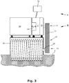
- Fig. 3 shows a drive train of the construction machine 1.
- a first drive train I is used to transmit the drive power to the driving devices 12, 16.
- a second drive train II is provided to transmit the drive power to the milling drum 20.
- the hydraulic drive train 70 is in the Fig. 4 explained in more detail.
- the drive train II for driving the milling drum 20 is shown in more detail.
- a drive motor, in particular an internal combustion engine 10 can be provided.
- the drive motor 10 can be provided via a flexible connection 22 with a pump distribution gear 17 for driving the first drive train I for driving a hydraulic drive system 70 for driving the driving device 12, 16.
- a clutch 15 can be provided between the drive motor 10 and the milling drum 20.
- the clutch 15 can be a device for switching the torque.
- a traction mechanism 13 for the mechanical drive of the milling drum 20 can be arranged between the clutch 15 and the milling drum 20.
- the traction mechanism 13 has a drive element 11 which is coupled in a rotationally fixed manner to the drive shaft of the drive motor 10.
- the traction mechanism 13 also has a drive element 21 which is coupled in a rotationally fixed manner to the drive shaft 19 of the milling drum 20.
- a transmission can also be arranged between the drive shaft 19 and the milling drum 20.
- the traction mechanism 13 is preferably a belt drive, whereby the drive and output elements can consist of belt pulleys 11, 21 over which one or more drive belts 31 run, whereby the drive and output elements can consist of pinions.
- the drive motor can also be hydraulic or electric.
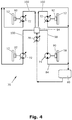
- Fig. 4 the hydraulic drive system 70 is shown roughly schematically.
- This hydraulic drive system has at least one hydraulic pump 78, preferably a hydraulic variable displacement pump.
- the hydraulic drive system 70 has a hydraulic fixed-displacement motor 74 for driving the driven driving device 16 and a hydraulic adjusting motor 72 in each case for driving the remaining driven driving devices 12.
- the hydraulic drive system can have a hydraulic reservoir 80.
- a hydraulic fixed-displacement motor has a smaller installation space than a hydraulic variable-displacement motor.
- a first gearbox 90 is arranged between the constant motor 74 and the associated driving device 16, and a second gear 92 is arranged between the remaining driven driving devices 12 and the respective hydraulic adjusting motors 72.
- the gear ratio of the first gear 90 between the constant motor 74 and the associated drive device 16 is lower than the respective gear ratios of the second gear 92, which are each arranged between the respective hydraulic adjusting motors 72 and the respective drive device 12.
- the transmission ratio is the ratio of the speed of the drive to the speed of the output or the torque of the output to the torque of the drive.
- the displacement of the constant motor 74 is smaller than the maximum displacement of the adjusting motors 72 achieved in the prior art. If the absorption volume of the constant motor 74 is smaller than the maximum absorption volume of the adjusting motors 72, the first transmission can also have the same transmission ratio as the respective second transmission.
- a hydraulic flow divider 94 can be provided which divides the hydraulic volume flow into partial volume flows 98, 100, a first partial volume flow 98 driving the constant motor 74 and the remaining partial volume flows 100 each driving a hydraulic adjusting motor 72.
- the first partial volume flow 98 and the remaining partial volume flows 100 are preferably not the same.
- the first partial volume flow 98 is preferably smaller than the respective remaining partial volume flows 100.
- the flow divider is an asymmetrical flow divider, whereby the first partial volume flow 98 is preferably a smaller volume flow than the remaining partial volume flows 100 the remaining driving equipment.
- FIG. 11 shows an alternative embodiment that corresponds to the embodiment from FIG Fig. 4 is very similar, but with the difference that, instead of the flow divider 94, a controllable valve 76, in particular a throttle valve, is arranged in the supply lines 82, 84 assigned to the hydraulic fixed-displacement motor 74.
- the hydraulic supply lines assigned to a hydraulic variable or constant motor are each the hydraulic lines in the hydraulic drive system 70, which run from the hydraulic pump to the respective variable or constant motor or also run from the respective variable or constant motor to a hydraulic reservoir.
- the The supply lines associated with the constant motor in the illustrated embodiment are the lines 82, 84.
- the supply line 82 leads from the hydraulic pump 78 to the hydraulic constant motor 74.
- the supply line 84 leads from the constant motor 74 to the hydraulic reservoir 80.
- the controllable valve 76 is arranged in the supply line 82 between the hydraulic pump 78 and the hydraulic constant motor 74.
- controllable valve 76 By means of the controllable valve 76, the hydraulic fixed-displacement motor 74 can be controlled in such a way that a behavior similar to that of a hydraulic variable-displacement motor can be achieved.
- the controllable valve 76 designed as a throttle valve is preferably a proportional valve. The pressure drop at the throttle valve and thus the hydraulic pressure at the hydraulic motor can be changed via the throttle valve, as a result of which the torque of the constant motor is adjusted.
- volume flow control valve instead of a throttle valve to regulate the volume flow and thus to specify the speed of the hydraulic motor and thus also of the driving device.
- the driving device 16 can be moved from a second pivoted-out position 26 into a first pivoted-in position 28 with the aid of a drive device 34. There can also be more than one swiveled-out position.
- the drive device 34 consists of a hydraulic piston-cylinder unit 33 with a push rod 35 and two link arms 36, 37.
- the link arm 37 is designed as a two-armed lever, one end being mounted on the machine frame 8 and the other end articulated to the second link arm 36 is.
- the other end of the second link arm 36 is connected to the link 44 of the pivot device.
- the push rod 35 can be actuated by the vehicle driver on the driver's cab 4.
- the driving device 16 In the retracted position of the push rod 35, the driving device 16 is in the second pivoted-out position, protruding over the zero side 24.
- the link mechanism In the extended state of the push rod 35, the link mechanism is 30 pivoted so that the driving device 16 can be moved into the first pivoted position. Before the pivoting process, the driving device 16 can be raised with the aid of the lifting column 48 so that the driving device 16 can be pivoted without contacting the ground.
- the link mechanism 30 can be locked in the first pivoted-in position.
- other pivoting devices are also known in which the pivoting can take place, for example, while maintaining the ground contact of the driving device 16.
- the pivotable driving device 16 can be pivotable about vertical pivot axes 40, 41.
- the vertical pivot axis about which the pivotable driving device can be pivoted can also be displaceable.
Landscapes
- Engineering & Computer Science (AREA)
- Mechanical Engineering (AREA)
- Mining & Mineral Resources (AREA)
- Architecture (AREA)
- Civil Engineering (AREA)
- Structural Engineering (AREA)
- General Engineering & Computer Science (AREA)
- Chemical & Material Sciences (AREA)
- Combustion & Propulsion (AREA)
- Transportation (AREA)
- Operation Control Of Excavators (AREA)
- Fluid-Pressure Circuits (AREA)
Applications Claiming Priority (1)
| Application Number | Priority Date | Filing Date | Title |
|---|---|---|---|
| DE102020204383.3A DE102020204383B4 (de) | 2020-04-03 | 2020-04-03 | Selbstfahrende Baumaschine |
Publications (2)
| Publication Number | Publication Date |
|---|---|
| EP3889355A1 true EP3889355A1 (fr) | 2021-10-06 |
| EP3889355B1 EP3889355B1 (fr) | 2023-08-02 |
Family
ID=75362484
Family Applications (1)
| Application Number | Title | Priority Date | Filing Date |
|---|---|---|---|
| EP21166679.7A Active EP3889355B1 (fr) | 2020-04-03 | 2021-04-01 | Engin de construction automoteur et méthode de travail de revêtement de sol |
Country Status (4)
| Country | Link |
|---|---|
| US (2) | US11519140B2 (fr) |
| EP (1) | EP3889355B1 (fr) |
| CN (2) | CN216193859U (fr) |
| DE (1) | DE102020204383B4 (fr) |
Families Citing this family (2)
| Publication number | Priority date | Publication date | Assignee | Title |
|---|---|---|---|---|
| DE102020204383B4 (de) * | 2020-04-03 | 2023-08-03 | Wirtgen Gmbh | Selbstfahrende Baumaschine |
| US11607952B1 (en) * | 2022-05-04 | 2023-03-21 | Dimaag-Ai, Inc. | Methods and systems for controlling differential wheel speeds of multi- independent-wheel drive vehicles |
Citations (2)
| Publication number | Priority date | Publication date | Assignee | Title |
|---|---|---|---|---|
| EP0916004A1 (fr) * | 1996-08-01 | 1999-05-19 | WIRTGEN GmbH | Engins de construction routiere pour fraiser des chaussees |
| US20130000996A1 (en) * | 2011-06-30 | 2013-01-03 | Caterpillar Inc. | Mobile machine with a support system |
Family Cites Families (16)
| Publication number | Priority date | Publication date | Assignee | Title |
|---|---|---|---|---|
| FR1314577A (fr) | 1961-11-30 | 1963-01-11 | Jacottet Paul Ets | Perfectionnements aux transmissions hydrauliques |
| US3298174A (en) * | 1965-06-11 | 1967-01-17 | Fairchild Hiller Corp | Control system for infinitely variable automatic transmission |
| US3637036A (en) | 1970-06-15 | 1972-01-25 | Cmi Corp | Hydrostatic drive system |
| IT1114651B (it) | 1977-05-31 | 1986-01-27 | Eaton Corp | Dispositivo di controllo idraulico |
| DE8915954U1 (de) * | 1989-03-09 | 1992-06-25 | O & K Orenstein & Koppel Ag, 1000 Berlin | Stufenlos regelbarer hydrostatischer Fahrantrieb |
| ATE133617T1 (de) * | 1993-10-29 | 1996-02-15 | Ec Eng & Consult Spezialmasch | Verfahren zum hydrostatischen antreiben eines fahrzeugs |
| JPH11190414A (ja) | 1997-12-25 | 1999-07-13 | Kayaba Ind Co Ltd | 変速装置 |
| DE102004040135B3 (de) | 2004-08-19 | 2005-12-15 | Abg Allgemeine Baumaschinen-Gesellschaft Mbh | Selbstfahrendes Gerät zum Abfräsen von Verkehrsflächen |
| WO2008042244A2 (fr) * | 2006-09-29 | 2008-04-10 | Volvo Construction Equipment Ab | systÈme de direction et de propulsion pour une FRAISEUSE ROUTIÈRE |
| DE102008027333A1 (de) * | 2008-06-07 | 2009-12-31 | Cnh Baumaschinen Gmbh | Steuerungsanordnung für Fahrzeuge mit hydrostatischem Zusatzantrieb |
| FR3001774B1 (fr) | 2013-02-04 | 2015-03-13 | Vianney Rabhi | Moteur-pompe hydraulique a cylindree fixe ou variable |
| DE102013216850B4 (de) * | 2013-08-23 | 2015-03-05 | Danfoss Power Solutions Gmbh & Co. Ohg | Ein-/aus-kuppelverfahren |
| KR20160108122A (ko) * | 2015-03-06 | 2016-09-19 | 가부시끼 가이샤 구보다 | 수확기의 동력 전달 장치, 수확기 및 농작업기 |
| DE102019120973A1 (de) * | 2019-08-02 | 2021-02-04 | Linde Hydraulics Gmbh & Co. Kg | Hydrostatischer Fahrantrieb einer allradgetriebenen Arbeitsmaschine |
| DE102019213473A1 (de) * | 2019-09-05 | 2021-03-11 | Robert Bosch Gmbh | Schaltstrategie für Fahrantrieb mit Summierungsgetriebe |
| DE102020204383B4 (de) | 2020-04-03 | 2023-08-03 | Wirtgen Gmbh | Selbstfahrende Baumaschine |
-
2020
- 2020-04-03 DE DE102020204383.3A patent/DE102020204383B4/de active Active
-
2021
- 2021-03-24 US US17/211,117 patent/US11519140B2/en active Active
- 2021-04-01 CN CN202120665685.7U patent/CN216193859U/zh active Active
- 2021-04-01 EP EP21166679.7A patent/EP3889355B1/fr active Active
- 2021-04-01 CN CN202110354344.2A patent/CN113494043B/zh active Active
-
2022
- 2022-12-01 US US18/073,005 patent/US11761157B2/en active Active
Patent Citations (2)
| Publication number | Priority date | Publication date | Assignee | Title |
|---|---|---|---|---|
| EP0916004A1 (fr) * | 1996-08-01 | 1999-05-19 | WIRTGEN GmbH | Engins de construction routiere pour fraiser des chaussees |
| US20130000996A1 (en) * | 2011-06-30 | 2013-01-03 | Caterpillar Inc. | Mobile machine with a support system |
Also Published As
| Publication number | Publication date |
|---|---|
| CN113494043A (zh) | 2021-10-12 |
| US11761157B2 (en) | 2023-09-19 |
| US20230160158A1 (en) | 2023-05-25 |
| US20210310203A1 (en) | 2021-10-07 |
| CN216193859U (zh) | 2022-04-05 |
| DE102020204383B4 (de) | 2023-08-03 |
| CN113494043B (zh) | 2023-03-10 |
| DE102020204383A1 (de) | 2021-10-07 |
| US11519140B2 (en) | 2022-12-06 |
| EP3889355B1 (fr) | 2023-08-02 |
Similar Documents
| Publication | Publication Date | Title |
|---|---|---|
| DE69715322T2 (de) | Gelenkfahrzeug-Lenkungseinrichtung mit Bogie-Rückführungssystem | |
| WO1996024725A1 (fr) | Engin pour travaux routiers | |
| DE102016216584A1 (de) | System und verfahren zum reagieren auf radschlupf in einem zugfahrzeug | |
| EP2296926B1 (fr) | Dispositif de commande pour véhicules à entraînement hydrostatique auxiliaire | |
| DE2528735A1 (de) | Hydrostatisches antriebssystem | |
| DE10120732A1 (de) | Anbauschnittstelle zwischen Arbeitsfahrzeug und Arbeitsgeräten sowie Steuereinrichtung | |
| DE3907633A1 (de) | Stufenlos regelbarer hydrostatischer fahrantrieb | |
| DE112010004297T5 (de) | Motor-Grader mit variablem Radstand | |
| DE102013204367A1 (de) | Achskonfiguration mit elektrischem Antrieb | |
| DE102016216588A1 (de) | System und verfahren zur erkennung von lastkräften an einem zugfahrzeug zum vorhersehen von radschlupf | |
| DE102013008939A1 (de) | Selbstfahrende Bodenfräsmaschine zum Bearbeiten von Bodenoberflächen mit einer Fräseinrichtung | |
| DE69617787T2 (de) | Lenkung für ein Knickrahmenfahrzeug | |
| EP3889355B1 (fr) | Engin de construction automoteur et méthode de travail de revêtement de sol | |
| DE2807351A1 (de) | Hydraulischer allradantrieb fuer fahrzeuge | |
| DE2652823A1 (de) | Bremsgelenktes fahrzeug, insbesondere zugmaschine, mit lenkhebel und einer hilfssteuerung mit selbstzentriervorrichtung | |
| EP0563515B1 (fr) | Dispositif d'entraînement pour machines de chantier ou véhicules de chantier | |
| DE102013009816A1 (de) | Bodenfräsmaschine, insbesondere Straßenkaltfräse | |
| DE7740374U1 (de) | Schlepperfahrzeug, insbesondere zur verwendung in der landwirtschaft | |
| DE102017221985B4 (de) | Zugkraftkraftbegrenzungseinrichtung für Arbeitsmaschine, stufenloses Getriebe, Arbeitsmaschine und Verfahren zur Zugkraftbegrenzung | |
| DE19539043B4 (de) | Hydrostatisch angetriebenes Fahrzeug | |
| EP3842592B1 (fr) | Engin de construction automobile | |
| DE102018126672A1 (de) | Rotorausfahrmechanismus für eine Maschine | |
| EP3034348B1 (fr) | Boîte de transfert destinée à répartir un couple sur au moins un premier et un second arbre primaire d'un véhicule automobile | |
| DE19616405B4 (de) | Vorrichtung zur Verhinderung des Aufstellens einer Tandemachse | |
| DE3642809A1 (de) | Maschine zum abfraesen oder abschaelen von strassenbelaegen |
Legal Events
| Date | Code | Title | Description |
|---|---|---|---|
| PUAI | Public reference made under article 153(3) epc to a published international application that has entered the european phase |
Free format text: ORIGINAL CODE: 0009012 |
|
| STAA | Information on the status of an ep patent application or granted ep patent |
Free format text: STATUS: THE APPLICATION HAS BEEN PUBLISHED |
|
| AK | Designated contracting states |
Kind code of ref document: A1 Designated state(s): AL AT BE BG CH CY CZ DE DK EE ES FI FR GB GR HR HU IE IS IT LI LT LU LV MC MK MT NL NO PL PT RO RS SE SI SK SM TR |
|
| STAA | Information on the status of an ep patent application or granted ep patent |
Free format text: STATUS: REQUEST FOR EXAMINATION WAS MADE |
|
| 17P | Request for examination filed |
Effective date: 20220406 |
|
| RBV | Designated contracting states (corrected) |
Designated state(s): AL AT BE BG CH CY CZ DE DK EE ES FI FR GB GR HR HU IE IS IT LI LT LU LV MC MK MT NL NO PL PT RO RS SE SI SK SM TR |
|
| GRAP | Despatch of communication of intention to grant a patent |
Free format text: ORIGINAL CODE: EPIDOSNIGR1 |
|
| STAA | Information on the status of an ep patent application or granted ep patent |
Free format text: STATUS: GRANT OF PATENT IS INTENDED |
|
| INTG | Intention to grant announced |
Effective date: 20230213 |
|
| GRAS | Grant fee paid |
Free format text: ORIGINAL CODE: EPIDOSNIGR3 |
|
| GRAA | (expected) grant |
Free format text: ORIGINAL CODE: 0009210 |
|
| STAA | Information on the status of an ep patent application or granted ep patent |
Free format text: STATUS: THE PATENT HAS BEEN GRANTED |
|
| P01 | Opt-out of the competence of the unified patent court (upc) registered |
Effective date: 20230527 |
|
| AK | Designated contracting states |
Kind code of ref document: B1 Designated state(s): AL AT BE BG CH CY CZ DE DK EE ES FI FR GB GR HR HU IE IS IT LI LT LU LV MC MK MT NL NO PL PT RO RS SE SI SK SM TR |
|
| REG | Reference to a national code |
Ref country code: GB Ref legal event code: FG4D Free format text: NOT ENGLISH |
|
| REG | Reference to a national code |
Ref country code: CH Ref legal event code: EP |
|
| REG | Reference to a national code |
Ref country code: DE Ref legal event code: R096 Ref document number: 502021001125 Country of ref document: DE |
|
| REG | Reference to a national code |
Ref country code: IE Ref legal event code: FG4D Free format text: LANGUAGE OF EP DOCUMENT: GERMAN |
|
| REG | Reference to a national code |
Ref country code: SE Ref legal event code: TRGR |
|
| REG | Reference to a national code |
Ref country code: LT Ref legal event code: MG9D |
|
| REG | Reference to a national code |
Ref country code: NL Ref legal event code: MP Effective date: 20230802 |
|
| PG25 | Lapsed in a contracting state [announced via postgrant information from national office to epo] |
Ref country code: GR Free format text: LAPSE BECAUSE OF FAILURE TO SUBMIT A TRANSLATION OF THE DESCRIPTION OR TO PAY THE FEE WITHIN THE PRESCRIBED TIME-LIMIT Effective date: 20231103 |
|
| PG25 | Lapsed in a contracting state [announced via postgrant information from national office to epo] |
Ref country code: IS Free format text: LAPSE BECAUSE OF FAILURE TO SUBMIT A TRANSLATION OF THE DESCRIPTION OR TO PAY THE FEE WITHIN THE PRESCRIBED TIME-LIMIT Effective date: 20231202 |
|
| PG25 | Lapsed in a contracting state [announced via postgrant information from national office to epo] |
Ref country code: RS Free format text: LAPSE BECAUSE OF FAILURE TO SUBMIT A TRANSLATION OF THE DESCRIPTION OR TO PAY THE FEE WITHIN THE PRESCRIBED TIME-LIMIT Effective date: 20230802 Ref country code: PT Free format text: LAPSE BECAUSE OF FAILURE TO SUBMIT A TRANSLATION OF THE DESCRIPTION OR TO PAY THE FEE WITHIN THE PRESCRIBED TIME-LIMIT Effective date: 20231204 Ref country code: NO Free format text: LAPSE BECAUSE OF FAILURE TO SUBMIT A TRANSLATION OF THE DESCRIPTION OR TO PAY THE FEE WITHIN THE PRESCRIBED TIME-LIMIT Effective date: 20231102 Ref country code: NL Free format text: LAPSE BECAUSE OF FAILURE TO SUBMIT A TRANSLATION OF THE DESCRIPTION OR TO PAY THE FEE WITHIN THE PRESCRIBED TIME-LIMIT Effective date: 20230802 Ref country code: LV Free format text: LAPSE BECAUSE OF FAILURE TO SUBMIT A TRANSLATION OF THE DESCRIPTION OR TO PAY THE FEE WITHIN THE PRESCRIBED TIME-LIMIT Effective date: 20230802 Ref country code: LT Free format text: LAPSE BECAUSE OF FAILURE TO SUBMIT A TRANSLATION OF THE DESCRIPTION OR TO PAY THE FEE WITHIN THE PRESCRIBED TIME-LIMIT Effective date: 20230802 Ref country code: IS Free format text: LAPSE BECAUSE OF FAILURE TO SUBMIT A TRANSLATION OF THE DESCRIPTION OR TO PAY THE FEE WITHIN THE PRESCRIBED TIME-LIMIT Effective date: 20231202 Ref country code: HR Free format text: LAPSE BECAUSE OF FAILURE TO SUBMIT A TRANSLATION OF THE DESCRIPTION OR TO PAY THE FEE WITHIN THE PRESCRIBED TIME-LIMIT Effective date: 20230802 Ref country code: GR Free format text: LAPSE BECAUSE OF FAILURE TO SUBMIT A TRANSLATION OF THE DESCRIPTION OR TO PAY THE FEE WITHIN THE PRESCRIBED TIME-LIMIT Effective date: 20231103 Ref country code: FI Free format text: LAPSE BECAUSE OF FAILURE TO SUBMIT A TRANSLATION OF THE DESCRIPTION OR TO PAY THE FEE WITHIN THE PRESCRIBED TIME-LIMIT Effective date: 20230802 |
|
| PG25 | Lapsed in a contracting state [announced via postgrant information from national office to epo] |
Ref country code: PL Free format text: LAPSE BECAUSE OF FAILURE TO SUBMIT A TRANSLATION OF THE DESCRIPTION OR TO PAY THE FEE WITHIN THE PRESCRIBED TIME-LIMIT Effective date: 20230802 |
|
| PG25 | Lapsed in a contracting state [announced via postgrant information from national office to epo] |
Ref country code: ES Free format text: LAPSE BECAUSE OF FAILURE TO SUBMIT A TRANSLATION OF THE DESCRIPTION OR TO PAY THE FEE WITHIN THE PRESCRIBED TIME-LIMIT Effective date: 20230802 |
|
| PG25 | Lapsed in a contracting state [announced via postgrant information from national office to epo] |
Ref country code: SM Free format text: LAPSE BECAUSE OF FAILURE TO SUBMIT A TRANSLATION OF THE DESCRIPTION OR TO PAY THE FEE WITHIN THE PRESCRIBED TIME-LIMIT Effective date: 20230802 Ref country code: RO Free format text: LAPSE BECAUSE OF FAILURE TO SUBMIT A TRANSLATION OF THE DESCRIPTION OR TO PAY THE FEE WITHIN THE PRESCRIBED TIME-LIMIT Effective date: 20230802 Ref country code: ES Free format text: LAPSE BECAUSE OF FAILURE TO SUBMIT A TRANSLATION OF THE DESCRIPTION OR TO PAY THE FEE WITHIN THE PRESCRIBED TIME-LIMIT Effective date: 20230802 Ref country code: EE Free format text: LAPSE BECAUSE OF FAILURE TO SUBMIT A TRANSLATION OF THE DESCRIPTION OR TO PAY THE FEE WITHIN THE PRESCRIBED TIME-LIMIT Effective date: 20230802 Ref country code: DK Free format text: LAPSE BECAUSE OF FAILURE TO SUBMIT A TRANSLATION OF THE DESCRIPTION OR TO PAY THE FEE WITHIN THE PRESCRIBED TIME-LIMIT Effective date: 20230802 Ref country code: CZ Free format text: LAPSE BECAUSE OF FAILURE TO SUBMIT A TRANSLATION OF THE DESCRIPTION OR TO PAY THE FEE WITHIN THE PRESCRIBED TIME-LIMIT Effective date: 20230802 Ref country code: SK Free format text: LAPSE BECAUSE OF FAILURE TO SUBMIT A TRANSLATION OF THE DESCRIPTION OR TO PAY THE FEE WITHIN THE PRESCRIBED TIME-LIMIT Effective date: 20230802 |
|
| REG | Reference to a national code |
Ref country code: DE Ref legal event code: R097 Ref document number: 502021001125 Country of ref document: DE |
|
| PLBE | No opposition filed within time limit |
Free format text: ORIGINAL CODE: 0009261 |
|
| STAA | Information on the status of an ep patent application or granted ep patent |
Free format text: STATUS: NO OPPOSITION FILED WITHIN TIME LIMIT |
|
| 26N | No opposition filed |
Effective date: 20240503 |
|
| PG25 | Lapsed in a contracting state [announced via postgrant information from national office to epo] |
Ref country code: SI Free format text: LAPSE BECAUSE OF FAILURE TO SUBMIT A TRANSLATION OF THE DESCRIPTION OR TO PAY THE FEE WITHIN THE PRESCRIBED TIME-LIMIT Effective date: 20230802 |
|
| PG25 | Lapsed in a contracting state [announced via postgrant information from national office to epo] |
Ref country code: BG Free format text: LAPSE BECAUSE OF FAILURE TO SUBMIT A TRANSLATION OF THE DESCRIPTION OR TO PAY THE FEE WITHIN THE PRESCRIBED TIME-LIMIT Effective date: 20230802 |
|
| PG25 | Lapsed in a contracting state [announced via postgrant information from national office to epo] |
Ref country code: MC Free format text: LAPSE BECAUSE OF FAILURE TO SUBMIT A TRANSLATION OF THE DESCRIPTION OR TO PAY THE FEE WITHIN THE PRESCRIBED TIME-LIMIT Effective date: 20230802 |
|
| PG25 | Lapsed in a contracting state [announced via postgrant information from national office to epo] |
Ref country code: MC Free format text: LAPSE BECAUSE OF FAILURE TO SUBMIT A TRANSLATION OF THE DESCRIPTION OR TO PAY THE FEE WITHIN THE PRESCRIBED TIME-LIMIT Effective date: 20230802 Ref country code: BG Free format text: LAPSE BECAUSE OF FAILURE TO SUBMIT A TRANSLATION OF THE DESCRIPTION OR TO PAY THE FEE WITHIN THE PRESCRIBED TIME-LIMIT Effective date: 20230802 |
|
| REG | Reference to a national code |
Ref country code: CH Ref legal event code: PL |
|
| PG25 | Lapsed in a contracting state [announced via postgrant information from national office to epo] |
Ref country code: LU Free format text: LAPSE BECAUSE OF NON-PAYMENT OF DUE FEES Effective date: 20240401 |
|
| REG | Reference to a national code |
Ref country code: BE Ref legal event code: MM Effective date: 20240430 |
|
| PG25 | Lapsed in a contracting state [announced via postgrant information from national office to epo] |
Ref country code: LU Free format text: LAPSE BECAUSE OF NON-PAYMENT OF DUE FEES Effective date: 20240401 |
|
| PG25 | Lapsed in a contracting state [announced via postgrant information from national office to epo] |
Ref country code: BE Free format text: LAPSE BECAUSE OF NON-PAYMENT OF DUE FEES Effective date: 20240430 |
|
| PG25 | Lapsed in a contracting state [announced via postgrant information from national office to epo] |
Ref country code: BE Free format text: LAPSE BECAUSE OF NON-PAYMENT OF DUE FEES Effective date: 20240430 Ref country code: CH Free format text: LAPSE BECAUSE OF NON-PAYMENT OF DUE FEES Effective date: 20240430 |
|
| PG25 | Lapsed in a contracting state [announced via postgrant information from national office to epo] |
Ref country code: IE Free format text: LAPSE BECAUSE OF NON-PAYMENT OF DUE FEES Effective date: 20240401 |
|
| PGFP | Annual fee paid to national office [announced via postgrant information from national office to epo] |
Ref country code: DE Payment date: 20250417 Year of fee payment: 5 |
|
| PGFP | Annual fee paid to national office [announced via postgrant information from national office to epo] |
Ref country code: IT Payment date: 20250430 Year of fee payment: 5 |
|
| PGFP | Annual fee paid to national office [announced via postgrant information from national office to epo] |
Ref country code: FR Payment date: 20250422 Year of fee payment: 5 |
|
| PGFP | Annual fee paid to national office [announced via postgrant information from national office to epo] |
Ref country code: AT Payment date: 20250721 Year of fee payment: 5 |
|
| PGFP | Annual fee paid to national office [announced via postgrant information from national office to epo] |
Ref country code: SE Payment date: 20250423 Year of fee payment: 5 |
|
| PG25 | Lapsed in a contracting state [announced via postgrant information from national office to epo] |
Ref country code: CY Free format text: LAPSE BECAUSE OF FAILURE TO SUBMIT A TRANSLATION OF THE DESCRIPTION OR TO PAY THE FEE WITHIN THE PRESCRIBED TIME-LIMIT; INVALID AB INITIO Effective date: 20210401 |
|
| PG25 | Lapsed in a contracting state [announced via postgrant information from national office to epo] |
Ref country code: HU Free format text: LAPSE BECAUSE OF FAILURE TO SUBMIT A TRANSLATION OF THE DESCRIPTION OR TO PAY THE FEE WITHIN THE PRESCRIBED TIME-LIMIT; INVALID AB INITIO Effective date: 20210401 |
|
| PG25 | Lapsed in a contracting state [announced via postgrant information from national office to epo] |
Ref country code: TR Free format text: LAPSE BECAUSE OF FAILURE TO SUBMIT A TRANSLATION OF THE DESCRIPTION OR TO PAY THE FEE WITHIN THE PRESCRIBED TIME-LIMIT Effective date: 20230802 |
|
| PGFP | Annual fee paid to national office [announced via postgrant information from national office to epo] |
Ref country code: GB Payment date: 20260324 Year of fee payment: 6 |