EP3889421A1 - Wellenenergieerzeugungsvorrichtung - Google Patents
Wellenenergieerzeugungsvorrichtung Download PDFInfo
- Publication number
- EP3889421A1 EP3889421A1 EP19889932.0A EP19889932A EP3889421A1 EP 3889421 A1 EP3889421 A1 EP 3889421A1 EP 19889932 A EP19889932 A EP 19889932A EP 3889421 A1 EP3889421 A1 EP 3889421A1
- Authority
- EP
- European Patent Office
- Prior art keywords
- floating body
- power transfer
- transfer member
- generation apparatus
- power generation
- Prior art date
- Legal status (The legal status is an assumption and is not a legal conclusion. Google has not performed a legal analysis and makes no representation as to the accuracy of the status listed.)
- Pending
Links
- 238000010248 power generation Methods 0.000 title claims abstract description 50
- 239000003643 water by type Substances 0.000 claims description 24
- 230000005540 biological transmission Effects 0.000 abstract 2
- 238000010586 diagram Methods 0.000 description 8
- 230000000694 effects Effects 0.000 description 2
- 238000012986 modification Methods 0.000 description 2
- 230000004048 modification Effects 0.000 description 2
- 230000004075 alteration Effects 0.000 description 1
- 230000008859 change Effects 0.000 description 1
- 239000012530 fluid Substances 0.000 description 1
- 238000000034 method Methods 0.000 description 1
- 230000001151 other effect Effects 0.000 description 1
- XLYOFNOQVPJJNP-UHFFFAOYSA-N water Substances O XLYOFNOQVPJJNP-UHFFFAOYSA-N 0.000 description 1
Images


Classifications
-
- F—MECHANICAL ENGINEERING; LIGHTING; HEATING; WEAPONS; BLASTING
- F03—MACHINES OR ENGINES FOR LIQUIDS; WIND, SPRING, OR WEIGHT MOTORS; PRODUCING MECHANICAL POWER OR A REACTIVE PROPULSIVE THRUST, NOT OTHERWISE PROVIDED FOR
- F03B—MACHINES OR ENGINES FOR LIQUIDS
- F03B13/00—Adaptations of machines or engines for special use; Combinations of machines or engines with driving or driven apparatus; Power stations or aggregates
- F03B13/12—Adaptations of machines or engines for special use; Combinations of machines or engines with driving or driven apparatus; Power stations or aggregates characterised by using wave or tide energy
- F03B13/14—Adaptations of machines or engines for special use; Combinations of machines or engines with driving or driven apparatus; Power stations or aggregates characterised by using wave or tide energy using wave energy
- F03B13/16—Adaptations of machines or engines for special use; Combinations of machines or engines with driving or driven apparatus; Power stations or aggregates characterised by using wave or tide energy using wave energy using the relative movement between a wave-operated member, i.e. a "wom" and another member, i.e. a reaction member or "rem"
- F03B13/18—Adaptations of machines or engines for special use; Combinations of machines or engines with driving or driven apparatus; Power stations or aggregates characterised by using wave or tide energy using wave energy using the relative movement between a wave-operated member, i.e. a "wom" and another member, i.e. a reaction member or "rem" where the other member, i.e. rem is fixed, at least at one point, with respect to the sea bed or shore
- F03B13/1845—Adaptations of machines or engines for special use; Combinations of machines or engines with driving or driven apparatus; Power stations or aggregates characterised by using wave or tide energy using wave energy using the relative movement between a wave-operated member, i.e. a "wom" and another member, i.e. a reaction member or "rem" where the other member, i.e. rem is fixed, at least at one point, with respect to the sea bed or shore and the wom slides relative to the rem
- F03B13/1865—Adaptations of machines or engines for special use; Combinations of machines or engines with driving or driven apparatus; Power stations or aggregates characterised by using wave or tide energy using wave energy using the relative movement between a wave-operated member, i.e. a "wom" and another member, i.e. a reaction member or "rem" where the other member, i.e. rem is fixed, at least at one point, with respect to the sea bed or shore and the wom slides relative to the rem where the connection between wom and conversion system takes tension only
-
- F—MECHANICAL ENGINEERING; LIGHTING; HEATING; WEAPONS; BLASTING
- F03—MACHINES OR ENGINES FOR LIQUIDS; WIND, SPRING, OR WEIGHT MOTORS; PRODUCING MECHANICAL POWER OR A REACTIVE PROPULSIVE THRUST, NOT OTHERWISE PROVIDED FOR
- F03B—MACHINES OR ENGINES FOR LIQUIDS
- F03B13/00—Adaptations of machines or engines for special use; Combinations of machines or engines with driving or driven apparatus; Power stations or aggregates
- F03B13/12—Adaptations of machines or engines for special use; Combinations of machines or engines with driving or driven apparatus; Power stations or aggregates characterised by using wave or tide energy
- F03B13/14—Adaptations of machines or engines for special use; Combinations of machines or engines with driving or driven apparatus; Power stations or aggregates characterised by using wave or tide energy using wave energy
- F03B13/16—Adaptations of machines or engines for special use; Combinations of machines or engines with driving or driven apparatus; Power stations or aggregates characterised by using wave or tide energy using wave energy using the relative movement between a wave-operated member, i.e. a "wom" and another member, i.e. a reaction member or "rem"
- F03B13/18—Adaptations of machines or engines for special use; Combinations of machines or engines with driving or driven apparatus; Power stations or aggregates characterised by using wave or tide energy using wave energy using the relative movement between a wave-operated member, i.e. a "wom" and another member, i.e. a reaction member or "rem" where the other member, i.e. rem is fixed, at least at one point, with respect to the sea bed or shore
- F03B13/1885—Adaptations of machines or engines for special use; Combinations of machines or engines with driving or driven apparatus; Power stations or aggregates characterised by using wave or tide energy using wave energy using the relative movement between a wave-operated member, i.e. a "wom" and another member, i.e. a reaction member or "rem" where the other member, i.e. rem is fixed, at least at one point, with respect to the sea bed or shore and the wom is tied to the rem
-
- F—MECHANICAL ENGINEERING; LIGHTING; HEATING; WEAPONS; BLASTING
- F03—MACHINES OR ENGINES FOR LIQUIDS; WIND, SPRING, OR WEIGHT MOTORS; PRODUCING MECHANICAL POWER OR A REACTIVE PROPULSIVE THRUST, NOT OTHERWISE PROVIDED FOR
- F03B—MACHINES OR ENGINES FOR LIQUIDS
- F03B15/00—Controlling
-
- F—MECHANICAL ENGINEERING; LIGHTING; HEATING; WEAPONS; BLASTING
- F03—MACHINES OR ENGINES FOR LIQUIDS; WIND, SPRING, OR WEIGHT MOTORS; PRODUCING MECHANICAL POWER OR A REACTIVE PROPULSIVE THRUST, NOT OTHERWISE PROVIDED FOR
- F03B—MACHINES OR ENGINES FOR LIQUIDS
- F03B15/00—Controlling
- F03B15/02—Controlling by varying liquid flow
- F03B15/04—Controlling by varying liquid flow of turbines
- F03B15/06—Regulating, i.e. acting automatically
- F03B15/14—Regulating, i.e. acting automatically by or of water level
-
- F—MECHANICAL ENGINEERING; LIGHTING; HEATING; WEAPONS; BLASTING
- F05—INDEXING SCHEMES RELATING TO ENGINES OR PUMPS IN VARIOUS SUBCLASSES OF CLASSES F01-F04
- F05B—INDEXING SCHEME RELATING TO WIND, SPRING, WEIGHT, INERTIA OR LIKE MOTORS, TO MACHINES OR ENGINES FOR LIQUIDS COVERED BY SUBCLASSES F03B, F03D AND F03G
- F05B2240/00—Components
- F05B2240/90—Mounting on supporting structures or systems
- F05B2240/91—Mounting on supporting structures or systems on a stationary structure
- F05B2240/917—Mounting on supporting structures or systems on a stationary structure attached to cables
-
- F—MECHANICAL ENGINEERING; LIGHTING; HEATING; WEAPONS; BLASTING
- F05—INDEXING SCHEMES RELATING TO ENGINES OR PUMPS IN VARIOUS SUBCLASSES OF CLASSES F01-F04
- F05B—INDEXING SCHEME RELATING TO WIND, SPRING, WEIGHT, INERTIA OR LIKE MOTORS, TO MACHINES OR ENGINES FOR LIQUIDS COVERED BY SUBCLASSES F03B, F03D AND F03G
- F05B2240/00—Components
- F05B2240/90—Mounting on supporting structures or systems
- F05B2240/93—Mounting on supporting structures or systems on a structure floating on a liquid surface
-
- F—MECHANICAL ENGINEERING; LIGHTING; HEATING; WEAPONS; BLASTING
- F05—INDEXING SCHEMES RELATING TO ENGINES OR PUMPS IN VARIOUS SUBCLASSES OF CLASSES F01-F04
- F05B—INDEXING SCHEME RELATING TO WIND, SPRING, WEIGHT, INERTIA OR LIKE MOTORS, TO MACHINES OR ENGINES FOR LIQUIDS COVERED BY SUBCLASSES F03B, F03D AND F03G
- F05B2270/00—Control
- F05B2270/30—Control parameters, e.g. input parameters
- F05B2270/342—Wave conditions, e.g. amplitude, frequency or direction
-
- Y—GENERAL TAGGING OF NEW TECHNOLOGICAL DEVELOPMENTS; GENERAL TAGGING OF CROSS-SECTIONAL TECHNOLOGIES SPANNING OVER SEVERAL SECTIONS OF THE IPC; TECHNICAL SUBJECTS COVERED BY FORMER USPC CROSS-REFERENCE ART COLLECTIONS [XRACs] AND DIGESTS
- Y02—TECHNOLOGIES OR APPLICATIONS FOR MITIGATION OR ADAPTATION AGAINST CLIMATE CHANGE
- Y02E—REDUCTION OF GREENHOUSE GAS [GHG] EMISSIONS, RELATED TO ENERGY GENERATION, TRANSMISSION OR DISTRIBUTION
- Y02E10/00—Energy generation through renewable energy sources
- Y02E10/30—Energy from the sea, e.g. using wave energy or salinity gradient
Definitions
- Example embodiments relate to a wave power generation apparatus.
- a wave power generation apparatus may generate electric power using the energy of waves.
- the wave power generation apparatus may include a floating body that floats on the surface of sea waters to capture such wave energy.
- a structure that may effectively absorb the wave energy may be required.
- a floating body that may adjust a degree of submergence of the floating body from the surface of waters based on a state of waves and for a wave power generation apparatus including the floating body.
- An aspect provides a wave power generation apparatus that may effectively absorb wave energy by adjusting a mooring angle of a floating body that is moored at a seabed.
- Another aspect provides a wave power generation apparatus that may effectively absorb wave energy irrespective of the depth of waters.
- a wave power generation apparatus including a floating body configured to float on a surface of sea waters, a power transfer member connected to the floating body and configured to receive power generated from a movement of the floating body and moor the floating body on the surface of sea waters, and a mooring angle adjustment module configured to adjust a mooring angle of the floating body with respect to the power transfer member based on a state of waves that act on the floating body.
- the mooring angle adjustment module may include a movable member connected to the floating body and configured to perform a translational motion in an outward direction of the floating body.
- the power transfer member may be fixed to a seabed below the floating body via the movable member.
- the mooring angle adjustment module may allow the movable member to perform the translational motion such that a distance between the floating body and a passing portion of the power transfer member associated with the movable member changes.
- the mooring angle adjustment module may further include a driver configured to allow the movable member to perform the translational motion, a sensor configured to sense the state of the waves that act on the floating body, and a controller configured to control an operation of the driver based on sensing information of the sensor.
- the sensing information may include at least one of a travel direction of the waves that act on the floating body, a height of the waves, a period of the waves, and a pattern of the waves.
- the driver may include a hydraulic cylinder.
- the movable member may be provided as a plurality of movable members in a radial form along a circumference of the floating body.
- the power transfer member may be provided as a plurality of power transfer members respectively passing through the movable members.
- the mooring angle adjustment module may further include a guide member disposed at an end of the movable member and configured to guide a movement of the power transfer member.
- a connecting portion of the power transfer member with respect to the floating body may be disposed above a connecting portion of the power transfer member with respect to the movable member.
- the wave power generation apparatus may further include an intermediate floating body configured to float underwater below the floating body and connected to the power transfer member.
- the floating body may be moored on the surface of sea waters above the intermediate floating body through the power transfer member.
- a wave power generation apparatus including a floating body configured to float on a surface of sea waters, a power transfer member of which one side is connected to the floating body and another side is fixed to a seabed below the floating body to allow the floating body to be moored on the surface of sea waters, a mooring angle adjustment module connected to the floating body and configured to adjust a mooring angle of the floating body with respect to the power transfer member, and a generation portion connected to the power transfer member and configured to generate power through kinetic energy of the floating body.
- the mooring angle adjustment module may include three movable members disposed separately from each other along a circumference of the floating body and configured to move toward an outer side of the floating body.
- the power transfer member may be provided as a plurality of power transfer members, and the power transfer members may be fixed to the seabed via the three movable members respectively.
- the mooring angle adjustment module may further include a sensor configured to sense a state of waves that act on the floating body, and a controller configured to control a movement of each of the three movable members based on sensing information of the sensor.
- the generation portion may include a drum around which the power transfer member is wound, a generator connected to the drum and configured to generate power through a rotation of the drum, and a tension force maintainer configured to maintain a tension force of the power transfer member by rotating the drum.
- the wave power generation apparatus may further include an intermediate floating body disposed underwater below the floating body and to which another side of the power transfer member is fixed.
- the floating body may be moored on the surface of sea waters above the intermediate floating body.
- a wave power generation apparatus may effectively absorb wave energy by adjusting a mooring angle of a floating body moored at a seabed.
- a wave power generation apparatus may effectively absorb wave energy irrespective of the depth of waters.
- first,” “second,” and “third” may be used herein to describe various members, components, regions, layers, or sections, these members, components, regions, layers, or sections are not to be limited by these terms. Rather, these terms are only used to distinguish one member, component, region, layer, or section from another member, component, region, layer, or section. Thus, a first member, component, region, layer, or section referred to in the examples described herein may also be referred to as a second member, component, region, layer, or section without departing from the teachings of the examples.
- FIG. 1 is a perspective view of a wave power generation apparatus according to an example embodiment.
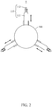
- FIG. 2 is a planar view of a wave power generation apparatus according to an example embodiment.
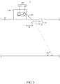
- FIG. 3 is a diagram illustrating an example of an operation of a wave power generation apparatus according to an example embodiment.
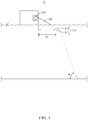
- FIG. 4 is a diagram illustrating another example of an operation of a wave power generation apparatus according to an example embodiment.
- FIG. 5 is a block diagram illustrating a wave power generation apparatus according to an example embodiment.
- a wave power generation apparatus 1 may generate electric power through wave energy.
- the wave power generation apparatus 1 may generate the power by absorbing kinetic energy of waves and converting the absorbed energy to mechanical kinetic energy.
- the wave power generation apparatus 1 may include a floating body 100, a power transfer member 120, a generation portion 140, and a mooring angle adjustment module 110.
- the floating body 100 may float on the surface of sea waters.
- the floating body 100 may absorb wave energy while moving on the surface of sea waters by waves.
- the floating body 100 may translate or rotate on the surface of sea waters by a movement of waves.
- the floating body 100 may perform a three degrees of freedom (3DoF) translational motion (heave, surge, sway) along X, Y, and Z axes, or a 3DoF rotational motion (yaw, pitch, roll) on the X, Y, and Z axes. That is, the floating body 100 may perform a 6DoF motion on the surface of sea waters.
- a degree of submergence of the floating body 100 which is a degree of the floating body 100 being submerged from the surface of sea waters, may be adjusted based on a state of waves.
- the power transfer member 120 may moor the floating body 100 on the surface of sea waters.
- one side of the power transfer member 120 may be connected to the floating body 100 and the other side thereof may be fixed to a seabed below the floating body 100 to allow the floating body 100 to be fixed at a certain location on the sea.
- the one side of the power transfer member 120 may be wound around a drum 141 provided in the floating body 100 and the other side thereof may be connected to a fixing roller 130 that is installed on the seabed, and thus the length may be adjusted by a movement of the floating body 100.
- the power transfer member 120 may receive power generated from a movement of the floating body 100 and convert the received power to linear kinetic energy, and transfer the energy to the generation portion 140 to be described hereinafter.
- the power transfer member 120 may be provided as a plurality of power transfer members 120, and the power transfer members 120 may be connected to the floating body 100.
- the power transfer members 120 may be respectively connected to three or more different locations on the floating body 100.
- the power transfer members 120 may be interlocked with a 6DoF movement of the floating body 100 and generate the linear kinetic energy.
- a case where three power transfer members 120 are connected to the floating body 100 will be described as an example for the convenience of description.
- the generation portion 140 may be connected to the power transfer member 120 and generate electric power through kinetic energy that is generated from a movement of the floating body 100.
- the generation portion 140 may include the drum 141, a generator 142, and a tension force maintainer (not shown).
- the power transfer member 120 may be wound.
- the drum 141 may be provided in the floating body 100, and rotate based on a linear movement of the power transfer member 120.
- the power transfer member 120 may be released from the drum 141 by a movement of the floating body 100 to increase the length thereof, and the drum 141 may rotate along the linear movement of the power transfer member 120 to convert the linear kinetic energy of the power transfer member 120 to rotational kinetic energy.
- the generator 142 may be connected to the drum 141 and generate power through a rotation of the drum 141.
- the generator 142 may be provided inside the floating body 100.
- the tension force maintainer may rotate the drum 141 to maintain a tension force of the power transfer member 120.
- the tension force maintainer may rotate the drum 141 in a direction in which the power transfer member 1 20 is wound around the drum 141 to maintain the tension force of the power transfer member 120 to be sufficient to receive energy of a fluid.
- the mooring angle adjustment module 110 may adjust a mooring angle of the floating body 100 with respect to the power transfer member 120 based on a state of waves that act on the floating body 100. For example, the mooring angle adjustment module 110 may adjust the mooring angle that is formed by the floating body 100 with each of the power transfer members 120 such that the floating body 100 absorbs wave energy effectively.
- the mooring angle adjustment module 110 may include a movable member 111, a guide member 112, a driver, a sensor 170, and a controller 160.
- the movable member 111 may be connected to the floating body 100 and perform a translational motion in an outward direction of the floating body 100.
- the power transfer member 120 may be connected to the other end of the movable member 111.
- a connecting portion of the power transfer member 120 with respect to the movable member 111 may be disposed below a connecting portion of the power transfer member 120 with respect to the floating body 100. That is, the power transfer member 120 may be fixed to the seabed below the floating body 100 via the movable member 111.
- the mooring angle adjustment module 110 may allow the movable member 111 to perform a translational motion to adjust a distance between the floating body 100 and a passing portion of the power transfer member 120 associated with the movable member 111.
- a mooring angle of the power transfer member 120 with respect to the floating body 120 may be adjusted.
- the movable member 111 may be provided as a plurality of movable members 111.
- the movable members 111 may be connected in a radial form along a circumference of the floating body 100 when observed from above the floating body 100.
- the movable members 111 may be respectively connected to the plurality of power transfer members 120.
- the plurality of power transfer members 120 For example, as illustrated in FIG. 2 , onto the circumference of the floating body 100, three movable members 111 may be connected, and three power transfer members 120 may be connected thereto respectively.
- the guide member 112 may be provided at an end of the movable member 111 through which the power transfer member 120 passes and may guide a movement of the power transfer member 120.
- the guide member 112 may be, for example, a roller around which the power transfer member 120 is wound. The roller may guide a movement of the power transfer member 120 while rotating on an axis, and concurrently set a path such that the power transfer member 120 passes through the end of the movable member 111.
- the driver may allow the movable member 111 to perform a translational motion.
- the driver may include a hydraulic cylinder that receives power and operates therewith.
- the hydraulic cylinder is provided merely as an example, and thus a type of the driver is not limited thereto.
- the sensor 170 may sense a state of waves that act on the floating body 100.
- the sensor 170 may obtain sensing information including at least one of a travel direction, a height, a period, and a pattern of the waves that act on the floating body 100.
- the controller 160 may control an operation of the driver based on the sensing information of the sensor 170.
- the controller 160 may adjust a mooring angle of the floating body 100 with respect to the power transfer member 120 based on the sensing information of the sensor 170 such that the floating body 100 absorbs wave energy effectively.
- the floating body 100 may float based on a movement of waves while being moored at a certain location on the surface of sea waters by the power transfer member 120.
- the mooring angle formed between the floating body 100 and the power transfer member 120 may change based on a point on the seabed at which the power transfer member 120 is fixed and a location of the floating body 100.
- the mooring angle between the floating body 100 and the power transfer member 120 may be an angle that is close to a vertical angle, for example, 90 degrees (°).
- energy generated by a movement of the floating body 100 may not be fully converted to linear energy of the power transfer member 120.
- the mooring angle adjustment module 110 may adjust an angle formed between the floating body 100 and the point on the seabed at which the power transfer member 120 is fixed, and thus assist the wave power generation apparatus 1 in effectively absorbing the energy generated by a movement of the floating body 100.
- the floating body 100 may have a mooring angle of ⁇ 1 with respect to the fixed point on the seabed.
- the floating body 100 may have an increased mooring angle of ⁇ 2 with respect to the fixed point on the seabed.
- the plurality of movable members 111 through which the power transfer members 120 pass respectively may individually translate in an outward direction of the floating body 100, and thus a mooring angle of the floating body 100 formed with respect to the seabed may be adjusted such that the power transfer members 120 effectively absorb a 6DoF movement of the floating body 100.
- the wave power generation apparatus 1 may adjust a mooring angle between the floating body 100 and each of the power transfer members 120 to most effectively absorb wave power based on a state of waves that act on the floating body 100.
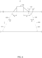
- FIG. 6 is a schematic diagram illustrating a wave power generation apparatus 1' according to an example embodiment.
- a wave power generation apparatus 1' may include a floating body 100, a power transfer member 120, a mooring angle adjustment module 110, and an intermediate floating body 150.
- the intermediate floating body 150 may be disposed underwater below the floating body 100.
- the intermediate floating body 150 may be fixed while being moored at the seabed through a fixing member 151.
- the floating body 100 may be connected to the intermediate floating body 150 through the power transfer member 120.
- one side of the power transfer member 120 may be connected to the floating body 100, and another side thereof may be fixed to the intermediate floating member 150. That is, the floating body 100 may be moored on the surface of sea waters above the intermediate floating body 150.
- the mooring angle adjustment module 110 may adjust a mooring angle of the floating body 100 with respect to a location at which the power transfer member 120 is fixed to the intermediate floating member 150.
- the mooring angle adjustment module 110 may adjust a relative location of the floating body 100 with respect to the intermediate floating body 150 by adjusting a distance between the floating body 100 and a plurality of power transfer members 120 connected to the floating body 100 as illustrated in FIG. 6 .
Landscapes
- Engineering & Computer Science (AREA)
- Chemical & Material Sciences (AREA)
- Combustion & Propulsion (AREA)
- Mechanical Engineering (AREA)
- General Engineering & Computer Science (AREA)
- Other Liquid Machine Or Engine Such As Wave Power Use (AREA)
Applications Claiming Priority (2)
| Application Number | Priority Date | Filing Date | Title |
|---|---|---|---|
| KR1020180148421A KR102202913B1 (ko) | 2018-11-27 | 2018-11-27 | 파력 발전 장치 |
| PCT/KR2019/016353 WO2020111721A1 (ko) | 2018-11-27 | 2019-11-26 | 파력 발전 장치 |
Publications (2)
| Publication Number | Publication Date |
|---|---|
| EP3889421A1 true EP3889421A1 (de) | 2021-10-06 |
| EP3889421A4 EP3889421A4 (de) | 2022-12-07 |
Family
ID=70852946
Family Applications (1)
| Application Number | Title | Priority Date | Filing Date |
|---|---|---|---|
| EP19889932.0A Pending EP3889421A4 (de) | 2018-11-27 | 2019-11-26 | Wellenenergieerzeugungsvorrichtung |
Country Status (4)
| Country | Link |
|---|---|
| US (1) | US11746738B2 (de) |
| EP (1) | EP3889421A4 (de) |
| KR (1) | KR102202913B1 (de) |
| WO (1) | WO2020111721A1 (de) |
Cited By (1)
| Publication number | Priority date | Publication date | Assignee | Title |
|---|---|---|---|---|
| EP4191051A1 (de) * | 2021-12-06 | 2023-06-07 | Oscillating Wave Energy Limited | Wellenenergieumwandlungsvorrichtung |
Families Citing this family (5)
| Publication number | Priority date | Publication date | Assignee | Title |
|---|---|---|---|---|
| KR102345300B1 (ko) | 2020-08-03 | 2021-12-29 | 박종원 | 파 에너지 수득 시스템 |
| KR20240096215A (ko) * | 2022-12-19 | 2024-06-26 | 주식회사 포스코 | 계류장치, 부유식 해상풍력장치 및 제어방법 |
| CN115875183B (zh) * | 2023-03-03 | 2023-05-23 | 青岛科技大学 | 一种波浪能发电系统及发电控制方法 |
| CN120062030B (zh) * | 2025-04-30 | 2025-06-27 | 武汉理工大学三亚科教创新园 | 一种贝壳仿生波浪能发电装置及其设计方法 |
| CN120332061B (zh) * | 2025-06-10 | 2025-09-02 | 水电水利规划设计总院 | 一种崖边潮汐冲击发电装置及方法 |
Family Cites Families (8)
| Publication number | Priority date | Publication date | Assignee | Title |
|---|---|---|---|---|
| US4516033A (en) * | 1983-05-31 | 1985-05-07 | Marvin Olson | Apparatus for converting flow of water into electrical power |
| US7371136B2 (en) * | 2006-01-20 | 2008-05-13 | Liquid Robotics Inc. | Wave power |
| KR20100130665A (ko) | 2009-06-04 | 2010-12-14 | 대우조선해양 주식회사 | 해양 부유 구조물 및 그것의 복합 계류 방법 |
| KR101306857B1 (ko) * | 2011-09-21 | 2013-09-10 | 한국전력공사 | 유압식 전력변환장치를 갖는 파력발전기 및 이를 이용한 전력변환방법 |
| GB201119292D0 (en) * | 2011-11-08 | 2011-12-21 | Marine Power Systems Ltd | Wave power generator |
| KR101379675B1 (ko) * | 2013-07-17 | 2014-03-31 | 김민우 | 복원력을 갖는 켈프 방식의 길이 가변형 계류장치 |
| GB2529210B (en) * | 2014-08-13 | 2018-01-31 | Gregory Bruce | Improved wave energy converter |
| KR101749036B1 (ko) * | 2015-06-24 | 2017-06-21 | 주식회사 인진 | 부유식 파력 발전 장치 |
-
2018
- 2018-11-27 KR KR1020180148421A patent/KR102202913B1/ko active Active
-
2019
- 2019-11-26 EP EP19889932.0A patent/EP3889421A4/de active Pending
- 2019-11-26 US US17/297,172 patent/US11746738B2/en active Active
- 2019-11-26 WO PCT/KR2019/016353 patent/WO2020111721A1/ko not_active Ceased
Cited By (1)
| Publication number | Priority date | Publication date | Assignee | Title |
|---|---|---|---|---|
| EP4191051A1 (de) * | 2021-12-06 | 2023-06-07 | Oscillating Wave Energy Limited | Wellenenergieumwandlungsvorrichtung |
Also Published As
| Publication number | Publication date |
|---|---|
| KR102202913B1 (ko) | 2021-01-14 |
| KR20200062714A (ko) | 2020-06-04 |
| US11746738B2 (en) | 2023-09-05 |
| WO2020111721A1 (ko) | 2020-06-04 |
| EP3889421A4 (de) | 2022-12-07 |
| US20220025841A1 (en) | 2022-01-27 |
Similar Documents
| Publication | Publication Date | Title |
|---|---|---|
| US11746738B2 (en) | Wave power generation apparatus | |
| CA2830891C (en) | Wave energy converter with asymmetrical float | |
| US20130241205A1 (en) | Power Generating Apparatus | |
| US12459615B2 (en) | Pivoting AUV/UUV dock for use with a wave energy converter | |
| JP5674805B2 (ja) | 波動エネルギー変換器および電力取り出しシステム | |
| US9885336B2 (en) | Wave power generation system | |
| US20130009402A1 (en) | Wave-energy converter | |
| US4134023A (en) | Apparatus for use in the extraction of energy from waves on water | |
| WO2012054152A1 (en) | Full-water-column surge-type wave-energy converter | |
| KR101671065B1 (ko) | 부유식 해상풍력발전장치 | |
| WO2018056094A1 (ja) | ケーブル布設構造および風力発電システム | |
| KR102532447B1 (ko) | 파력 발전기 | |
| JP7369122B2 (ja) | ドライブ組立体 | |
| EP3368719B1 (de) | Mit mitteln zur rückgewinnung von energie aus wellenbewegung ausgestattete küstenschutzinfrastruktur | |
| WO2014063258A1 (en) | Method and system for harnessing hydrokinetic energy | |
| KR101662410B1 (ko) | 부유식 해상 구조물 | |
| JP6150046B2 (ja) | 海流発電装置 | |
| KR20200045897A (ko) | 풍력 발전기 설치 선박 | |
| NL2029383B1 (en) | A method of electrically connecting a floating offshore substation | |
| KR20130000589A (ko) | 공진을 이용한 양력면형 조류발전기 | |
| KR20200045899A (ko) | 횡동요 방지용 부유식 구조물 | |
| WO2009154475A2 (en) | Wave power plant |
Legal Events
| Date | Code | Title | Description |
|---|---|---|---|
| STAA | Information on the status of an ep patent application or granted ep patent |
Free format text: STATUS: THE INTERNATIONAL PUBLICATION HAS BEEN MADE |
|
| PUAI | Public reference made under article 153(3) epc to a published international application that has entered the european phase |
Free format text: ORIGINAL CODE: 0009012 |
|
| STAA | Information on the status of an ep patent application or granted ep patent |
Free format text: STATUS: REQUEST FOR EXAMINATION WAS MADE |
|
| 17P | Request for examination filed |
Effective date: 20210623 |
|
| AK | Designated contracting states |
Kind code of ref document: A1 Designated state(s): AL AT BE BG CH CY CZ DE DK EE ES FI FR GB GR HR HU IE IS IT LI LT LU LV MC MK MT NL NO PL PT RO RS SE SI SK SM TR |
|
| DAV | Request for validation of the european patent (deleted) | ||
| DAX | Request for extension of the european patent (deleted) | ||
| A4 | Supplementary search report drawn up and despatched |
Effective date: 20221108 |
|
| RIC1 | Information provided on ipc code assigned before grant |
Ipc: F03B 15/14 20060101ALI20221102BHEP Ipc: F03B 13/18 20060101AFI20221102BHEP |