EP3889448B1 - Élément de fixation - Google Patents
Élément de fixation Download PDFInfo
- Publication number
- EP3889448B1 EP3889448B1 EP21160157.0A EP21160157A EP3889448B1 EP 3889448 B1 EP3889448 B1 EP 3889448B1 EP 21160157 A EP21160157 A EP 21160157A EP 3889448 B1 EP3889448 B1 EP 3889448B1
- Authority
- EP
- European Patent Office
- Prior art keywords
- component
- fastening
- sleeve
- receptacle
- fastening element
- Prior art date
- Legal status (The legal status is an assumption and is not a legal conclusion. Google has not performed a legal analysis and makes no representation as to the accuracy of the status listed.)
- Active
Links
Images


Classifications
-
- F—MECHANICAL ENGINEERING; LIGHTING; HEATING; WEAPONS; BLASTING
- F16—ENGINEERING ELEMENTS AND UNITS; GENERAL MEASURES FOR PRODUCING AND MAINTAINING EFFECTIVE FUNCTIONING OF MACHINES OR INSTALLATIONS; THERMAL INSULATION IN GENERAL
- F16B—DEVICES FOR FASTENING OR SECURING CONSTRUCTIONAL ELEMENTS OR MACHINE PARTS TOGETHER, e.g. NAILS, BOLTS, CIRCLIPS, CLAMPS, CLIPS OR WEDGES; JOINTS OR JOINTING
- F16B5/00—Joining sheets or plates, e.g. panels, to one another or to strips or bars parallel to them
- F16B5/02—Joining sheets or plates, e.g. panels, to one another or to strips or bars parallel to them by means of fastening members using screw-thread
- F16B5/0283—Joining sheets or plates, e.g. panels, to one another or to strips or bars parallel to them by means of fastening members using screw-thread with an externally threaded sleeve around the neck or the head of the screw-threaded element for adjustably fastening a plate or frame or the like to a fixed element
-
- F—MECHANICAL ENGINEERING; LIGHTING; HEATING; WEAPONS; BLASTING
- F16—ENGINEERING ELEMENTS AND UNITS; GENERAL MEASURES FOR PRODUCING AND MAINTAINING EFFECTIVE FUNCTIONING OF MACHINES OR INSTALLATIONS; THERMAL INSULATION IN GENERAL
- F16B—DEVICES FOR FASTENING OR SECURING CONSTRUCTIONAL ELEMENTS OR MACHINE PARTS TOGETHER, e.g. NAILS, BOLTS, CIRCLIPS, CLAMPS, CLIPS OR WEDGES; JOINTS OR JOINTING
- F16B2/00—Friction-grip releasable fastenings
-
- F—MECHANICAL ENGINEERING; LIGHTING; HEATING; WEAPONS; BLASTING
- F16—ENGINEERING ELEMENTS AND UNITS; GENERAL MEASURES FOR PRODUCING AND MAINTAINING EFFECTIVE FUNCTIONING OF MACHINES OR INSTALLATIONS; THERMAL INSULATION IN GENERAL
- F16B—DEVICES FOR FASTENING OR SECURING CONSTRUCTIONAL ELEMENTS OR MACHINE PARTS TOGETHER, e.g. NAILS, BOLTS, CIRCLIPS, CLAMPS, CLIPS OR WEDGES; JOINTS OR JOINTING
- F16B43/00—Washers or equivalent devices; Other devices for supporting bolt-heads or nuts
- F16B43/02—Washers or equivalent devices; Other devices for supporting bolt-heads or nuts with special provisions for engaging surfaces which are not perpendicular to a bolt axis or do not surround the bolt
-
- B—PERFORMING OPERATIONS; TRANSPORTING
- B60—VEHICLES IN GENERAL
- B60Q—ARRANGEMENT OF SIGNALLING OR LIGHTING DEVICES, THE MOUNTING OR SUPPORTING THEREOF OR CIRCUITS THEREFOR, FOR VEHICLES IN GENERAL
- B60Q1/00—Arrangement of optical signalling or lighting devices, the mounting or supporting thereof or circuits therefor
- B60Q1/02—Arrangement of optical signalling or lighting devices, the mounting or supporting thereof or circuits therefor the devices being primarily intended to illuminate the way ahead or to illuminate other areas of way or environments
- B60Q1/04—Arrangement of optical signalling or lighting devices, the mounting or supporting thereof or circuits therefor the devices being primarily intended to illuminate the way ahead or to illuminate other areas of way or environments the devices being headlights
- B60Q1/06—Arrangement of optical signalling or lighting devices, the mounting or supporting thereof or circuits therefor the devices being primarily intended to illuminate the way ahead or to illuminate other areas of way or environments the devices being headlights adjustable, e.g. remotely-controlled from inside vehicle
-
- B—PERFORMING OPERATIONS; TRANSPORTING
- B60—VEHICLES IN GENERAL
- B60Q—ARRANGEMENT OF SIGNALLING OR LIGHTING DEVICES, THE MOUNTING OR SUPPORTING THEREOF OR CIRCUITS THEREFOR, FOR VEHICLES IN GENERAL
- B60Q1/00—Arrangement of optical signalling or lighting devices, the mounting or supporting thereof or circuits therefor
- B60Q1/26—Arrangement of optical signalling or lighting devices, the mounting or supporting thereof or circuits therefor the devices being primarily intended to indicate the vehicle, or parts thereof, or to give signals, to other traffic
- B60Q1/2619—Arrangement of optical signalling or lighting devices, the mounting or supporting thereof or circuits therefor the devices being primarily intended to indicate the vehicle, or parts thereof, or to give signals, to other traffic built in the vehicle body
- B60Q1/2623—Details of the fastening means
- B60Q1/2626—Screw-nut fasteners
-
- B—PERFORMING OPERATIONS; TRANSPORTING
- B60—VEHICLES IN GENERAL
- B60Q—ARRANGEMENT OF SIGNALLING OR LIGHTING DEVICES, THE MOUNTING OR SUPPORTING THEREOF OR CIRCUITS THEREFOR, FOR VEHICLES IN GENERAL
- B60Q1/00—Arrangement of optical signalling or lighting devices, the mounting or supporting thereof or circuits therefor
- B60Q1/26—Arrangement of optical signalling or lighting devices, the mounting or supporting thereof or circuits therefor the devices being primarily intended to indicate the vehicle, or parts thereof, or to give signals, to other traffic
- B60Q1/2619—Arrangement of optical signalling or lighting devices, the mounting or supporting thereof or circuits therefor the devices being primarily intended to indicate the vehicle, or parts thereof, or to give signals, to other traffic built in the vehicle body
- B60Q1/2642—Arrangement of optical signalling or lighting devices, the mounting or supporting thereof or circuits therefor the devices being primarily intended to indicate the vehicle, or parts thereof, or to give signals, to other traffic built in the vehicle body with provision for adjusting the alignment of the device housing with respect to the vehicle body
-
- F—MECHANICAL ENGINEERING; LIGHTING; HEATING; WEAPONS; BLASTING
- F16—ENGINEERING ELEMENTS AND UNITS; GENERAL MEASURES FOR PRODUCING AND MAINTAINING EFFECTIVE FUNCTIONING OF MACHINES OR INSTALLATIONS; THERMAL INSULATION IN GENERAL
- F16B—DEVICES FOR FASTENING OR SECURING CONSTRUCTIONAL ELEMENTS OR MACHINE PARTS TOGETHER, e.g. NAILS, BOLTS, CIRCLIPS, CLAMPS, CLIPS OR WEDGES; JOINTS OR JOINTING
- F16B43/00—Washers or equivalent devices; Other devices for supporting bolt-heads or nuts
- F16B43/001—Washers or equivalent devices; Other devices for supporting bolt-heads or nuts for sealing or insulation
-
- F—MECHANICAL ENGINEERING; LIGHTING; HEATING; WEAPONS; BLASTING
- F16—ENGINEERING ELEMENTS AND UNITS; GENERAL MEASURES FOR PRODUCING AND MAINTAINING EFFECTIVE FUNCTIONING OF MACHINES OR INSTALLATIONS; THERMAL INSULATION IN GENERAL
- F16B—DEVICES FOR FASTENING OR SECURING CONSTRUCTIONAL ELEMENTS OR MACHINE PARTS TOGETHER, e.g. NAILS, BOLTS, CIRCLIPS, CLAMPS, CLIPS OR WEDGES; JOINTS OR JOINTING
- F16B5/00—Joining sheets or plates, e.g. panels, to one another or to strips or bars parallel to them
- F16B5/02—Joining sheets or plates, e.g. panels, to one another or to strips or bars parallel to them by means of fastening members using screw-thread
-
- F—MECHANICAL ENGINEERING; LIGHTING; HEATING; WEAPONS; BLASTING
- F16—ENGINEERING ELEMENTS AND UNITS; GENERAL MEASURES FOR PRODUCING AND MAINTAINING EFFECTIVE FUNCTIONING OF MACHINES OR INSTALLATIONS; THERMAL INSULATION IN GENERAL
- F16B—DEVICES FOR FASTENING OR SECURING CONSTRUCTIONAL ELEMENTS OR MACHINE PARTS TOGETHER, e.g. NAILS, BOLTS, CIRCLIPS, CLAMPS, CLIPS OR WEDGES; JOINTS OR JOINTING
- F16B5/00—Joining sheets or plates, e.g. panels, to one another or to strips or bars parallel to them
- F16B5/02—Joining sheets or plates, e.g. panels, to one another or to strips or bars parallel to them by means of fastening members using screw-thread
- F16B5/0216—Joining sheets or plates, e.g. panels, to one another or to strips or bars parallel to them by means of fastening members using screw-thread the position of the plates to be connected being adjustable
- F16B5/0233—Joining sheets or plates, e.g. panels, to one another or to strips or bars parallel to them by means of fastening members using screw-thread the position of the plates to be connected being adjustable allowing for adjustment perpendicular to the plane of the plates
Definitions
- the invention relates to a fastening element for a component, in particular for fastening to a body part of a vehicle.
- the EP 2 933 144 A1 discloses a device for at least partially fastening a motor vehicle light in an installation opening of a body of a motor vehicle, a motor vehicle light equipped therewith and a method for arranging and adjusting such a device on a motor vehicle light.
- the device comprises a hollow screw with an external thread and a central opening that extends coaxially to the longitudinal axis of the hollow screw, a threaded bolt that can be fixed to the motor vehicle light and has a first threaded section that extends through the central opening, and a hollow screw in the central opening on the first threaded section that is coaxial between the hollow screw and the sleeve-shaped clamping part arranged on the threaded bolt.
- the hollow screw has a radially protruding collar which is arranged on one side of the external thread and faces the device of the motor vehicle light in the installed state.
- the clamping part is rotatably arranged in the central opening.
- the clamping part is arranged in a form-fitting manner in the axial direction parallel to the longitudinal axis.
- the clamping part has a continuous axial opening which runs coaxially to the longitudinal axis and whose inner diameter is smaller than the outer diameter of the first thread section.
- the clamp includes a lug having a tool-engageable configuration for rotating the clamp. At least one stop groove is arranged in the collar of the hollow screw.
- a stop which is fixed to the motor vehicle light and which stops in the assembled state of the device engages in at least one stop groove.
- the method provides for first fixing the threaded bolt on the motor vehicle light, then screwing the hollow screw with the clamping part arranged in its central opening with the collar first onto the first thread section until the stop fixed on the motor vehicle light engages in a stop groove, and then by turning of the clamping part relative to the first thread section to adjust the position of the hollow screw along the threaded bolt.
- the object of the present invention is to specify an improved fastening element.
- the fastening element according to the invention represents a detachable tolerance compensation element with subsequent axial adjustment and radial tolerance compensation.
- the fastening element makes it possible to produce a (non-positive and/or positive) connection between two components, for example a body and an attachment, by simply inserting and fastening the sleeve in the first component and screwing in the connecting element in the second component. After assembly, the fastening element can be adjusted by rotating the connecting element in the axial direction and separated again by later pulling the connecting element out of the clip. The set position remains for re-fastening.
- the first component can be a carrier component, for example, in particular a body panel of a vehicle.
- the second component can, for example, be an add-on part such as a rear light or a side light.
- the second fastening area has a threaded section for engaging in a receptacle of the second component.
- the threaded section can be designed as a self-tapping or metric thread, in particular self-locking, which positively and/or non-positively engages in a receptacle of the second component, which in particular is screwed into the receptacle.
- the second fastening area can be fixed in the second component, in particular pressed in, glued in, injected or clipped in, or formed in one piece with the second component.
- the drive interface is designed as a lower drive interface that is inserted into the compensating element Connection element points away and/or the drive interface is designed as an upper drive interface, which points towards the connection element inserted into the compensating element. In this way, the compensating element can be adjusted when the sleeve is fastened in the first component and the connecting element is screwed into the second component.
- the drive interface comprises an external or internal hexagon or square, an external or internal hexalobe, a slot or a cross slot.
- Other forms of drive interface are also possible.
- the compensating element and the sleeve have mutually complementary threads. In this way, the adjustment can be made in the longitudinal direction by twisting.
- the connecting element is detachable in the receptacle, but is held in a manner that prevents it from being pulled out. In this way, the second component can be removed from the first component and reattached. The axial distance previously adjusted by twisting the connecting element in the second component is retained.
- the compensating element is designed to be elastic in the area of the receptacle.
- a separating flange is provided on the connecting element to separate the first fastening area from the second fastening area.
- a nut is provided for screwing onto the sleeve in order to hold the fastening element on the first component by means of a screw connection.
- clip connections are also possible.
- the nut and sleeve have complementary serrations configured to make the nut more difficult to loosen or lose.
- a spring element is arranged in the receptacle for the positive and/or frictional connection of the compensating element to the connecting element.
- a spring element which is fixed axially in both directions within the receptacle, can transmit forces such as an insertion force and an extraction force, in particular compressive or tensile forces, axially in both directions and dissipate them in the direction of the receptacle, so that the fastening element can be used several times.
- the sleeve has an interface for receiving in the receiving opening of the first component, the interface having a cross section that deviates from the circular shape and/or the interface having a smaller cross section than the receiving opening. This makes it more difficult for the sleeve to rotate in the receiving opening and/or allows the position to be adjusted transversely to the longitudinal direction.
- figure 1 is a schematic view of a fastening element 1 for connecting a first component 4 to a second component 6 and for compensating for tolerances between the first component 4 and the second component 6.
- figure 2 shows a schematic view of the fastening element 1 obliquely from below with a view of a lower drive interface 1.12.
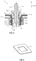
- figure 3 shows a schematic sectional view of the fastener 1.
- figure 4 is a schematic view a section of the first component 4 with a receiving opening 4.1.
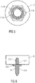
- figure 5 12 is a schematic view of the fastener 1 from below.
- the fastening element 1 can be essentially cylindrical and has a sleeve 1.1.
- the fastening element 1 can be designed in one or more parts and can be formed, for example, from a metal or plastic material or from a combination of metal parts and plastic parts.
- the sleeve 1.1 has a head section 1.3, which can be designed as a sealing element, for example in the form of a disk or a mushroom head, and has a larger diameter than the sleeve 1.1.
- the head section 1.3 can also include only at least two sectors, for example three sectors, of a mushroom head.
- the sleeve 1.1 forms a socket of the fastening element 1.
- the sleeve 1.1 and the head section 1.3 can be formed as one component, in particular made of plastic.
- the sleeve 1.1 and the head section 1.3 are designed as a 2-component plastic injection molded part.
- the sleeve 1.1 can be made of a harder plastic material and the head section 1.3 can be made of a softer plastic material.
- a compensating element 1.4 can be arranged in the sleeve 1.1 in an adjustable manner, in particular adjustable in an axial direction y of the sleeve 1.1.
- the sleeve 1.1 and the compensating element 1.4 can be provided with mutually complementary threads 1.8, 1.9.
- the compensating element 1.4 is provided with a receptacle 1.2, in particular in the form of a hollow cylinder.
- a spring element 2 can be arranged in the receptacle 1.2, for example made of metal, in particular of a steel material, preferably spring steel.
- the fastening element 1 has a pin-like connecting element 5 .
- the first component 4 is, for example, a carrier component, in particular a body panel of a vehicle.
- the receiving opening 4.1 can have a cross section that deviates from the circular shape.
- the sleeve 1.1 can have an interface 1.5 that is complementary to the receiving opening 4.1.
- the receiving opening 4.1 can be made larger than the interface 1.5 in order to allow a position compensation in transverse directions x and z transverse to the axial direction y of the sleeve 1.1.
- the receiving opening 4.1 and the interface 1.5 can each have an approximately square cross section, preferably with rounded corners.
- the receptacle 1.2 in the compensating element 1.4 is open on at least one side, in particular on the head side, to accommodate a connecting element 5.
- the receptacle 1.2 can also be designed as a through-opening at the bottom end and thus be open on both sides.
- the fastening element 1 can be preassembled on the first component 4, for example on the vehicle side.
- the fastening element 1 can be arranged in a receiving opening 4.1 of the first component 4 by means of a latching or clamping connection and can be held there in a positive and/or non-positive manner.
- Nut 1.6 is provided, which can be screwed onto the sleeve 1.1 in order to hold the fastening element 1 on the first component 4 by means of a screw connection.
- further complementary threads 1.10, 1.11 can be provided in the nut 1.6 and on the sleeve 1.1.
- the nut 1.6 can have a collar 1.7 for resting on the first component 4.
- the connecting element 5 can be preassembled on the second component 6, for example on the mounting side on the rear light or side light.
- the connecting element 5 has a threaded section 5.1.
- Threaded section 5.1 can be designed as a self-tapping or metric thread, in particular self-locking, which engages, in particular screws, in a receptacle of second component 6 in a positive and/or non-positive manner.
- the connecting element 5 can be fixed in the second component 6, for example pressed in, glued in, injected or clipped in.
- the connecting element 5 is then fastened to the first component 4 with the preassembled second component 6, the connection of the two components 4 and 6 being axially adjustable.
- the connecting element 5 is designed as a bolt which has a separating flange 5.6 for separating a first fastening area 5.4 for the receptacle 1.2 in the compensating element 1.4 from a second fastening area 5.5 for the second component 6.
- the separating flange 5.6 protrudes radially outwards and is disk-shaped in the manner of a bolt collar and can be provided with a hexagon or square.
- a lower drive interface 1.12 is provided on the compensating element 1.4, for example an external or internal hexagon or square, an external or internal hexalobe, a slot or a Phillips slot.
- the lower drive interface 1.12 points in particular away from the connecting element 5 used in the compensating element 1.4 and can of the sleeve 1.1 protrude when the compensating element 1.4 is arranged in the sleeve 1.1.
- an upper drive interface 1.13 is provided as an alternative or in addition to the compensating element 1.4, for example an external or internal hexagon or square, an external or internal hexalobe, a slot or a Phillips slot.
- the upper drive interface 1.13 points in particular to the connecting element 5 inserted into the compensating element 1.4 and is accessible in particular when the connecting element 5 is not inserted into the compensating element 1.4.
- the nut 1.6 and the compensating element 1.4 can have mutually complementary toothing 1.14, 1.15, which makes it difficult or impossible to loosen or lose the nut 1.6.
- An assembly can be formed by fastening the threaded section 5.1 in the receptacle of the second component 6, for example by screwing it in, as in FIG figure 6 shown.
- the threaded section 5.1 can, for example, be screwed in until the separating flange 5.6 hits the second component 6.
- This connection for example via the spring element 2, can be released again by pulling the connecting element 5 out of the receptacle 1.2.
- the compensating element 1.4 can be designed to be correspondingly elastic.
- the sleeve 1.1 with the compensating element 1.4 inserted therein is already attached to the connecting element 5 before the assembly of the components 4, 6, for example in a form-fitting and/or friction-fitting manner.
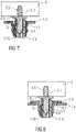
- the assembly comprising the second component 6 and the fastening element 1 fastened in the receptacle, can be fed to the first component 4, for example a body panel of a vehicle, with the sleeve 1.1 being able to be inserted into the receptacle opening 4.1 of the first component 4, as shown in FIG figure 8 shown.
- figure 8 is a schematic view of the fastening element 1 inserted into the first component 4 and the second component 6 connected thereto.
- a position compensation can take place in the transverse directions x and z transverse to the axial direction y of the sleeve 1.1.
- the section 4.1 can also have a smaller diameter than the head section 1.3.
- figure 9 is a schematic view of the fastening element 1 inserted into the first component 4 and of the second component 6 connected thereto, with the nut 1.6 being screwed onto the sleeve 1.1.
- the fastening element 1 is thus fastened to the first component 4 and fixed with respect to the transverse directions x and z.
- FIG. 10 is a schematic view of the fastening element 1 after the second component 6 has been pulled off the first component 4.
- the upper drive interface 1.13 is also accessible, so that the compensating element 1.4 can also be adjusted in the axial direction y in this way.
- the receptacle 1.2 and the connecting element 5 in the first fastening area 5.4 can comprise a circumferential groove of the connecting element 5 and a bulge of the receptacle 1.2 complementary thereto.
- the receptacle 1.2 and the connecting element 5 in the first fastening area 5.4 can comprise a radial bulge of the connecting element 5 and a circumferential groove complementary thereto in the receptacle 1.2.
- the receptacle 1.2 and the connecting element 5 in the first fastening area 5.4 can comprise a radial bulge of the connecting element 5 and a circumferential groove complementary thereto in the receptacle 1.2, the bulge facing the connecting element 5 in the direction of the second component 6 at a shallower angle can run than in the opposite direction, so that the connecting element 5 can be inserted more easily into the receptacle 1.2 than it can be pulled out.
- the connecting element 5 can have a circumferential groove in the first fastening area 5.4 and the receptacle 1.2 can have elastic arms on its inside which are complementary thereto and which engage in the groove.
- the elastic arms can be fastened to the receptacle 1.2 at their end facing the head section 1.3 and protrude in the opposite direction.
- the groove in the connecting element 5 can run at a steeper angle to the connecting element 5 in the direction away from the second component 6 than in the opposite direction, so that the connecting element 5 can be inserted more easily into the receptacle 1.2 than it can be pulled out.
- the connecting element 5 can have a circumferential groove in the first fastening area 5.4 and the receptacle 1.2 can have a complementary bulge on its inside, which engages in the groove.
- the groove in the connecting element 5 can run at a steeper angle to the connecting element 5 in the direction away from the second component 6 than in the opposite direction, so that the connecting element 5 can be inserted more easily into the receptacle 1.2 than it can be pulled out.
- the connecting element 5 can be formed cylindrically in the first fastening area 5.4 and the receptacle 1.2 can also be formed cylindrically on its inside, complementary thereto.
- the connecting element 5 can be essentially cylindrical in the first fastening area 5.4 and provided with ribbing, and the receptacle 1.2 can also be essentially cylindrical on its inside.
- a spring element 2 is arranged in the receptacle 1.2 and is firmly connected axially in both directions to an inside of the receptacle 1.2.
- Such a spring element 2 which is fixed axially in both directions within the receptacle 1.2, can transmit forces, such as an insertion force and an extraction force, in particular compressive or tensile forces, axially in both directions and divert them in the direction of the receptacle 1.2, so that the fastening element 1 can be attached several times can be used.
- the sleeve 1.1 is made of plastic and the spring element 2 is made of metal.
- the spring element 2 comprises, for example, a base body from which spring arms protrude radially outwards, which are positively and/or non-positively connected to the inside of recording 1.2 intervene.
- spring arms By means of the spring arms, axially acting forces and their derivation in both directions can be set in a targeted manner.
- the base body of the spring element 2 is, for example, sleeve-shaped.
- the multiple spring arms are arranged or formed one above the other in multiple rows, for example, along a longitudinal extent of the base body.
- the spring arms can be arranged or formed diametrically opposite one another with respect to the base body. Such an arrangement of spring arms on the base body, in particular on two sides or in two rows, enables symmetrical force transmission and dissipation.
- a one-sided or single-row arrangement of spring arms can be formed on the base body, which enables asymmetrical force transmission and dissipation.
- the base body can have a wavy section in some areas outside of the rows of spring arms. This wave-shaped section of the base body enables a frictional or clamping connection with the inside of the receptacle 1.2 outside of the positive and/or non-positive connection of the spring arms with the inside.
- the spring arms can protrude radially outwards and then, when inserted in the receptacle 1.2, penetrate into the inside of the receptacle 1.2 and form a positive and/or non-positive fit with the inside of the receptacle 1.2.
- the base body can have spring arms which are directed radially inwards and protrude radially inwards from the base body.
- adjacent spring arms and at least one of the rows alternately have spring ends pointing radially outwards and radially inwards.
- the spring arms of one or the respective row can be arranged at an axial distance from one another. This enables the connection to be adjusted axially, for example by means of appropriate spacing in adjustment steps. This enables axial adjustment steps to compensate for tolerances, in particular small component tolerances, in small steps of, for example, 0.2 cm to 1 cm, in particular 0.35 cm.
- the spring arms can be designed as latching arms, ratchets or clamping arms or in another suitable form which enables a positive and/or non-positive fit with an adjacent surface, such as the inside of the receptacle 1.2.
- the receptacle 1.2 can be formed like a funnel in the area of the head section 1.3 in order to facilitate the insertion of the connecting element 5.
Landscapes
- Engineering & Computer Science (AREA)
- General Engineering & Computer Science (AREA)
- Mechanical Engineering (AREA)
- Connection Of Plates (AREA)
- Bolts, Nuts, And Washers (AREA)
Claims (10)
- Élément de fixation (1) servant à connecter un premier composant (4) à un deuxième composant (6), l'élément de fixation (1) présentant :- un élément de connexion (5) de type goupille doté d'une première région de fixation (5.4) et d'une deuxième région de fixation (5.5),- une douille (1.1), qui est configurée pour l'insertion dans une ouverture de logement (4.1) du premier composant (4),- un élément de compensation (1.4), qui est doté d'un logement (1.2) pour le logement de la première région de fixation (5.4) et qui est configuré pour l'insertion et le réglage dans une direction longitudinale (y) dans la douille (1.1),au moins une interface d'entraînement (1.12, 1.13) étant prévue sur l'élément de compensation (1.4), interface au moyen de laquelle l'élément de compensation (1.4) est réglable dans la direction longitudinale (y) dans la douille (1.1).
- Élément de fixation (1) selon la revendication 1, la deuxième région de fixation (5.5) présentant une partie filetée (5.1) pour l'entrée en prise dans un logement du deuxième composant (6) ou la deuxième région de fixation (5.5) étant fixée, en particulier enfoncée, collée, injectée ou enclipsée dans le deuxième composant (6) ou étant réalisée d'un seul tenant avec le deuxième composant (6).
- Élément de fixation (1) selon la revendication 1 ou 2, l'interface d'entraînement (1.12, 1.13) étant réalisée sous la forme d'une interface d'entraînement inférieure (1.12), qui est détournée de l'élément de connexion (5) inséré dans l'élément de compensation (1.4) et/ou l'interface entraînement (1.12, 1.13) étant réalisée sous la forme d'une interface d'entraînement supérieure (1.13), qui est tournée vers l'élément de connexion (5) inséré dans l'élément de compensation (1.4).
- Élément de fixation (1) selon l'une des revendications précédentes, l'interface d'entraînement (1.12, 1.13) comprenant une empreinte à six pans ou quatre pans extérieurs ou intérieurs, une empreinte à six lobes externes ou internes, une fente ou une fente cruciforme.
- Élément de fixation (1) selon l'une des revendications précédentes, l'élément de compensation (1.4) et la douille (1.1) présentant des filetages (1.8, 1.9) complémentaires l'un à l'autre.
- Élément de fixation (1) selon l'une des revendications précédentes, une collerette de séparation (5.6) étant prévue sur l'élément de connexion (5) pour la séparation de la première région de fixation (5.4) de la deuxième région de fixation (5.5).
- Élément de fixation (1) selon l'une des revendications précédentes, un écrou (1.6) étant prévu pour le vissage sur la douille (1.1), afin de retenir l'élément de fixation (1) sur le premier composant (4) au moyen d'une connexion vissée.
- Élément de fixation (1) selon la revendication 7, l'écrou (1.6) et la douille (1.1) présentant des dentures (1.14, 1.15) complémentaires l'une à l'autre, qui sont configurées pour entraver le desserrage ou la perte de l'écrou (1.6).
- Élément de fixation (1) selon l'une des revendications précédentes, un élément ressort (2) servant à la connexion par complémentarité de formes et/ou par friction de l'élément de compensation (1.4) sur l'élément de connexion (5) étant disposé dans le logement (1.2).
- Élément de fixation (1) selon l'une des revendications précédentes, la douille (1.1) présentant une interface (1.5) pour le logement dans l'ouverture de logement (4.1) du premier composant (4), l'interface (1.5) présentant une section transversale différant de la forme circulaire et/ou l'interface (1.5) présentant une plus petite section transversale que l'ouverture de logement (4.1).
Applications Claiming Priority (1)
| Application Number | Priority Date | Filing Date | Title |
|---|---|---|---|
| DE102020204180.6A DE102020204180A1 (de) | 2020-03-31 | 2020-03-31 | Befestigungselement |
Publications (2)
| Publication Number | Publication Date |
|---|---|
| EP3889448A1 EP3889448A1 (fr) | 2021-10-06 |
| EP3889448B1 true EP3889448B1 (fr) | 2022-08-03 |
Family
ID=74859181
Family Applications (1)
| Application Number | Title | Priority Date | Filing Date |
|---|---|---|---|
| EP21160157.0A Active EP3889448B1 (fr) | 2020-03-31 | 2021-03-02 | Élément de fixation |
Country Status (4)
| Country | Link |
|---|---|
| US (1) | US11725689B2 (fr) |
| EP (1) | EP3889448B1 (fr) |
| CN (1) | CN113464523B (fr) |
| DE (1) | DE102020204180A1 (fr) |
Families Citing this family (4)
| Publication number | Priority date | Publication date | Assignee | Title |
|---|---|---|---|---|
| DE102021205410A1 (de) * | 2021-05-27 | 2022-12-01 | Witte Automotive Gmbh | Vorrichtung zum Ausgleichen von Toleranzen zwischen zwei miteinander zu verbindenden Bauteilen |
| USD1048871S1 (en) * | 2022-04-25 | 2024-10-29 | Kelvin James Matthews | Fastening device |
| DE102022127873A1 (de) | 2022-10-21 | 2024-05-02 | Audi Aktiengesellschaft | Befestigungselement, Bauteilanordnung und Verfahren zum Befestigen eines ersten Bauteils und eines zweiten Bauteils aneinander mittels eines Befestigungselements |
| DE102023205357B3 (de) | 2023-06-08 | 2024-09-19 | Witte Automotive Gmbh | Vorrichtung zum Ausgleichen von Toleranzen zwischen zwei miteinander zu verbindenden Bauteilen |
Family Cites Families (29)
| Publication number | Priority date | Publication date | Assignee | Title |
|---|---|---|---|---|
| US6357953B1 (en) * | 1999-12-16 | 2002-03-19 | General Motors Corporation | Tolerance compensation apparatus |
| DE20021194U1 (de) * | 2000-12-14 | 2002-04-18 | Schwarzbich, Jörg, 33615 Bielefeld | Vorrichtung zum Verbinden von Bauteilen |
| DE10151383A1 (de) | 2001-10-18 | 2003-04-30 | Boellhoff Gmbh | Toleranzausgleichsanordnung |
| US7488135B2 (en) * | 2003-07-29 | 2009-02-10 | Aoyama Seisakusho Co., Ltd. | Fastening device |
| DE10353376B4 (de) * | 2003-11-14 | 2005-09-08 | Airbus Deutschland Gmbh | Vorrichtung und Verfahren zur mechanischen Verbindung von zwei Bauteilen |
| GB2412704A (en) | 2004-03-29 | 2005-10-05 | Hella Mfg Ltd | Adjustable fastening device |
| DE202005009017U1 (de) * | 2005-06-08 | 2005-08-25 | Böllhoff Verbindungstechnik GmbH | Toleranzausgleichsanordnung aus Kunststoff |
| DE202005010873U1 (de) * | 2005-07-11 | 2005-09-22 | Böllhoff Verbindungstechnik GmbH | Toleranzausgleichseinrichtung aus Kunststoff |
| DE102005044064A1 (de) | 2005-09-15 | 2007-03-22 | GM Global Technology Operations, Inc., Detroit | Schraubenverbindung mit Toleranzausgleich |
| US20070207012A1 (en) | 2006-03-06 | 2007-09-06 | Nissan Technical Center North America, Inc. | Tolerance compensating mounting device |
| DE102006034463B3 (de) | 2006-07-26 | 2008-01-10 | A. Raymond Et Cie | Vorrichtung zum Befestigen eines Anbauteiles und eines Trägerteiles in einem Abstand voneinander |
| DE202006012493U1 (de) * | 2006-08-14 | 2006-11-02 | Böllhoff Verbindungstechnik GmbH | Befestigungseinrichtung mit Toleranzausgleich |
| DE202007016945U1 (de) * | 2007-12-05 | 2008-05-15 | Böllhoff Verbindungstechnik GmbH | Verstellelement |
| DE202008011318U1 (de) * | 2008-08-28 | 2008-11-06 | Böllhoff Verbindungstechnik GmbH | Befestigungsanordnung mit Toleranzausgleich |
| DE202009007421U1 (de) * | 2009-05-25 | 2009-08-20 | Db Netz Ag | Vorrichtung zur vorgespannten Verankerung der Ankerschrauben von Masten, vorzugsweise von Signalmasten |
| KR101086609B1 (ko) * | 2009-06-01 | 2011-11-23 | 현대자동차주식회사 | 카울 크로스바 마운팅 조립체 |
| DE102011001052A1 (de) | 2011-03-03 | 2012-09-06 | Böllhoff Verbindungstechnik GmbH | Befestigungseinrichtung mit Toleranzausgleich |
| CN103906657B (zh) | 2011-10-31 | 2016-07-20 | 黑拉许克联合股份有限公司 | 用于前照灯的调整装置 |
| DE202012102440U1 (de) * | 2012-07-03 | 2013-10-07 | Jörg Schwarzbich | Toleranzausgleichselement |
| DE102013202582B4 (de) * | 2013-02-18 | 2023-07-27 | Witte Automotive Gmbh | Toleranzausgleichsvorrichtung |
| CA2931689C (fr) | 2013-11-27 | 2020-01-21 | Heiko Schmidt | Dispositif de fixation ajustable et procede de fabrication d'un module prefabrique a partir d'au moins un dispositif de fixation ajustable et d'une piece |
| DE102014100697A1 (de) | 2014-01-22 | 2015-07-23 | Jörg Schwarzbich | Verfahren zum Setzen einer Blindnietmutter mit Toleranzausgleichselement |
| EP2933144B1 (fr) | 2014-04-16 | 2016-05-25 | odelo GmbH | Feu de véhicule automobile comprenant un dispositif destiné à la fixation au moins partielle du feu dans une ouverture de carrosserie et procédé d'agencement et de réglage d'un tel dispositif sur un feu de véhicule automobile |
| EP3227566B1 (fr) | 2015-03-06 | 2018-11-28 | Aoyama Seisakusho Co., Ltd. | Outil de fixation avec fonction de mise à la terre |
| DE102016118640B4 (de) | 2016-09-30 | 2024-10-17 | Witte Automotive Gmbh | Federelement |
| DE102017124470A1 (de) | 2017-10-19 | 2019-04-25 | Böllhoff Verbindungstechnik GmbH | Toleranzausgleichsanordnung |
| DE102017130605A1 (de) | 2017-12-19 | 2019-06-19 | Böllhoff Verbindungstechnik GmbH | Toleranzausgleichsanordnung mit Klemmsicherung |
| DE102017131235A1 (de) * | 2017-12-22 | 2019-06-27 | Witte Automotive Gmbh | Toleranzausgleichsvorrichtung |
| DE102019212136A1 (de) * | 2019-08-13 | 2021-02-18 | Witte Automotive Gmbh | Befestigungselement und Toleranzausgleichsvorrichtung |
-
2020
- 2020-03-31 DE DE102020204180.6A patent/DE102020204180A1/de not_active Ceased
-
2021
- 2021-03-02 EP EP21160157.0A patent/EP3889448B1/fr active Active
- 2021-03-15 US US17/200,979 patent/US11725689B2/en active Active
- 2021-03-22 CN CN202110302341.4A patent/CN113464523B/zh active Active
Also Published As
| Publication number | Publication date |
|---|---|
| US11725689B2 (en) | 2023-08-15 |
| US20210301862A1 (en) | 2021-09-30 |
| DE102020204180A1 (de) | 2021-09-30 |
| EP3889448A1 (fr) | 2021-10-06 |
| CN113464523B (zh) | 2022-12-23 |
| CN113464523A (zh) | 2021-10-01 |
Similar Documents
| Publication | Publication Date | Title |
|---|---|---|
| EP3889448B1 (fr) | Élément de fixation | |
| DE4310002C1 (de) | Schallentkoppelndes Verbindungselement | |
| DE60206536T2 (de) | Vorrichtung zum Halten von Schrauben | |
| EP1979634B1 (fr) | Unité de montage destinée à un anneau de fixation d'une boucle de ceinture | |
| EP0353468B1 (fr) | Elément de connexion | |
| DE202007008152U1 (de) | Befestigungseinrichtung mit Toleranzausgleich | |
| DE19929966A1 (de) | Sicherungssystem für einen Bolzen und eine Mutter | |
| DE102021105786A1 (de) | Toleranzausgleichsanordnung | |
| DE69501636T2 (de) | Einsatzmutter und Befestigungselement | |
| DE102008049640A1 (de) | Befestigungselement | |
| DE102020204176A1 (de) | Befestigungselement | |
| EP3736464B1 (fr) | Entretoise pour un agencement de fixation, agencement de fixation doté d'une telle entretoise ainsi que procédé de fixation d'une pièce de montage sur une pièce de support | |
| WO2023020739A1 (fr) | Élément de compensation de tolérance ayant un boulon à double filetage, liaison par vis entre deux composants au moyen de l'élément de compensation de tolérance, et procédé de production de l'élément de compensation de tolérance | |
| EP1612432B1 (fr) | Dispositif de fixation pour habillage et méthode de fixation | |
| EP4411151B1 (fr) | Élément de réglage doté d'un manchon de fixation amortissant et son procédé d'installation et de fabrication | |
| DE102019206750B4 (de) | Vorrichtung zum Ausgleichen von Toleranzen zwischen einem ersten Bauteil und einem zweiten Bauteil | |
| DE10109660B4 (de) | Sicherungsring und Befestigungsvorrichtung für eine Welle-Nabe-Verbindung | |
| DE60210820T2 (de) | Befestigungsvorrichtung und -verfahren zur befestigung eines objekts an einer stützkonstruktion | |
| DE10107581B4 (de) | Vorrichtung zur Verbindung eines Kunststoffteils mit einem flachen Trägerteil | |
| EP0866231B1 (fr) | Dispositif de fixation préfabriqué | |
| DE10153699A1 (de) | Mutter | |
| WO2026082857A1 (fr) | Attache rapide, liaison entre deux composants avec l'attache rapide et procédé de liaison et son procédé de production | |
| DE102020204179A1 (de) | Befestigungselement | |
| DE102024205638A1 (de) | Vorrichtung zum Ausgleichen von Toleranzen zwischen zwei miteinander zu verbindenden Bauteilen | |
| CH719255A2 (de) | Verbindungsanordnung und Profilverbindungsanordnung. |
Legal Events
| Date | Code | Title | Description |
|---|---|---|---|
| PUAI | Public reference made under article 153(3) epc to a published international application that has entered the european phase |
Free format text: ORIGINAL CODE: 0009012 |
|
| STAA | Information on the status of an ep patent application or granted ep patent |
Free format text: STATUS: REQUEST FOR EXAMINATION WAS MADE |
|
| 17P | Request for examination filed |
Effective date: 20210803 |
|
| AK | Designated contracting states |
Kind code of ref document: A1 Designated state(s): AL AT BE BG CH CY CZ DE DK EE ES FI FR GB GR HR HU IE IS IT LI LT LU LV MC MK MT NL NO PL PT RO RS SE SI SK SM TR |
|
| GRAP | Despatch of communication of intention to grant a patent |
Free format text: ORIGINAL CODE: EPIDOSNIGR1 |
|
| STAA | Information on the status of an ep patent application or granted ep patent |
Free format text: STATUS: GRANT OF PATENT IS INTENDED |
|
| INTG | Intention to grant announced |
Effective date: 20220316 |
|
| GRAS | Grant fee paid |
Free format text: ORIGINAL CODE: EPIDOSNIGR3 |
|
| GRAA | (expected) grant |
Free format text: ORIGINAL CODE: 0009210 |
|
| STAA | Information on the status of an ep patent application or granted ep patent |
Free format text: STATUS: THE PATENT HAS BEEN GRANTED |
|
| AK | Designated contracting states |
Kind code of ref document: B1 Designated state(s): AL AT BE BG CH CY CZ DE DK EE ES FI FR GB GR HR HU IE IS IT LI LT LU LV MC MK MT NL NO PL PT RO RS SE SI SK SM TR |
|
| REG | Reference to a national code |
Ref country code: AT Ref legal event code: REF Ref document number: 1508966 Country of ref document: AT Kind code of ref document: T Effective date: 20220815 Ref country code: CH Ref legal event code: EP |
|
| REG | Reference to a national code |
Ref country code: DE Ref legal event code: R096 Ref document number: 502021000087 Country of ref document: DE |
|
| REG | Reference to a national code |
Ref country code: IE Ref legal event code: FG4D Free format text: LANGUAGE OF EP DOCUMENT: GERMAN |
|
| REG | Reference to a national code |
Ref country code: LT Ref legal event code: MG9D |
|
| REG | Reference to a national code |
Ref country code: NL Ref legal event code: MP Effective date: 20220803 |
|
| PG25 | Lapsed in a contracting state [announced via postgrant information from national office to epo] |
Ref country code: SE Free format text: LAPSE BECAUSE OF FAILURE TO SUBMIT A TRANSLATION OF THE DESCRIPTION OR TO PAY THE FEE WITHIN THE PRESCRIBED TIME-LIMIT Effective date: 20220803 Ref country code: RS Free format text: LAPSE BECAUSE OF FAILURE TO SUBMIT A TRANSLATION OF THE DESCRIPTION OR TO PAY THE FEE WITHIN THE PRESCRIBED TIME-LIMIT Effective date: 20220803 Ref country code: PT Free format text: LAPSE BECAUSE OF FAILURE TO SUBMIT A TRANSLATION OF THE DESCRIPTION OR TO PAY THE FEE WITHIN THE PRESCRIBED TIME-LIMIT Effective date: 20221205 Ref country code: NO Free format text: LAPSE BECAUSE OF FAILURE TO SUBMIT A TRANSLATION OF THE DESCRIPTION OR TO PAY THE FEE WITHIN THE PRESCRIBED TIME-LIMIT Effective date: 20221103 Ref country code: NL Free format text: LAPSE BECAUSE OF FAILURE TO SUBMIT A TRANSLATION OF THE DESCRIPTION OR TO PAY THE FEE WITHIN THE PRESCRIBED TIME-LIMIT Effective date: 20220803 Ref country code: LV Free format text: LAPSE BECAUSE OF FAILURE TO SUBMIT A TRANSLATION OF THE DESCRIPTION OR TO PAY THE FEE WITHIN THE PRESCRIBED TIME-LIMIT Effective date: 20220803 Ref country code: LT Free format text: LAPSE BECAUSE OF FAILURE TO SUBMIT A TRANSLATION OF THE DESCRIPTION OR TO PAY THE FEE WITHIN THE PRESCRIBED TIME-LIMIT Effective date: 20220803 Ref country code: FI Free format text: LAPSE BECAUSE OF FAILURE TO SUBMIT A TRANSLATION OF THE DESCRIPTION OR TO PAY THE FEE WITHIN THE PRESCRIBED TIME-LIMIT Effective date: 20220803 Ref country code: ES Free format text: LAPSE BECAUSE OF FAILURE TO SUBMIT A TRANSLATION OF THE DESCRIPTION OR TO PAY THE FEE WITHIN THE PRESCRIBED TIME-LIMIT Effective date: 20220803 |
|
| PG25 | Lapsed in a contracting state [announced via postgrant information from national office to epo] |
Ref country code: PL Free format text: LAPSE BECAUSE OF FAILURE TO SUBMIT A TRANSLATION OF THE DESCRIPTION OR TO PAY THE FEE WITHIN THE PRESCRIBED TIME-LIMIT Effective date: 20220803 Ref country code: IS Free format text: LAPSE BECAUSE OF FAILURE TO SUBMIT A TRANSLATION OF THE DESCRIPTION OR TO PAY THE FEE WITHIN THE PRESCRIBED TIME-LIMIT Effective date: 20221203 Ref country code: HR Free format text: LAPSE BECAUSE OF FAILURE TO SUBMIT A TRANSLATION OF THE DESCRIPTION OR TO PAY THE FEE WITHIN THE PRESCRIBED TIME-LIMIT Effective date: 20220803 Ref country code: GR Free format text: LAPSE BECAUSE OF FAILURE TO SUBMIT A TRANSLATION OF THE DESCRIPTION OR TO PAY THE FEE WITHIN THE PRESCRIBED TIME-LIMIT Effective date: 20221104 |
|
| PG25 | Lapsed in a contracting state [announced via postgrant information from national office to epo] |
Ref country code: SM Free format text: LAPSE BECAUSE OF FAILURE TO SUBMIT A TRANSLATION OF THE DESCRIPTION OR TO PAY THE FEE WITHIN THE PRESCRIBED TIME-LIMIT Effective date: 20220803 Ref country code: RO Free format text: LAPSE BECAUSE OF FAILURE TO SUBMIT A TRANSLATION OF THE DESCRIPTION OR TO PAY THE FEE WITHIN THE PRESCRIBED TIME-LIMIT Effective date: 20220803 Ref country code: DK Free format text: LAPSE BECAUSE OF FAILURE TO SUBMIT A TRANSLATION OF THE DESCRIPTION OR TO PAY THE FEE WITHIN THE PRESCRIBED TIME-LIMIT Effective date: 20220803 Ref country code: CZ Free format text: LAPSE BECAUSE OF FAILURE TO SUBMIT A TRANSLATION OF THE DESCRIPTION OR TO PAY THE FEE WITHIN THE PRESCRIBED TIME-LIMIT Effective date: 20220803 |
|
| REG | Reference to a national code |
Ref country code: DE Ref legal event code: R097 Ref document number: 502021000087 Country of ref document: DE |
|
| PG25 | Lapsed in a contracting state [announced via postgrant information from national office to epo] |
Ref country code: SK Free format text: LAPSE BECAUSE OF FAILURE TO SUBMIT A TRANSLATION OF THE DESCRIPTION OR TO PAY THE FEE WITHIN THE PRESCRIBED TIME-LIMIT Effective date: 20220803 Ref country code: EE Free format text: LAPSE BECAUSE OF FAILURE TO SUBMIT A TRANSLATION OF THE DESCRIPTION OR TO PAY THE FEE WITHIN THE PRESCRIBED TIME-LIMIT Effective date: 20220803 |
|
| PLBE | No opposition filed within time limit |
Free format text: ORIGINAL CODE: 0009261 |
|
| STAA | Information on the status of an ep patent application or granted ep patent |
Free format text: STATUS: NO OPPOSITION FILED WITHIN TIME LIMIT |
|
| PG25 | Lapsed in a contracting state [announced via postgrant information from national office to epo] |
Ref country code: AL Free format text: LAPSE BECAUSE OF FAILURE TO SUBMIT A TRANSLATION OF THE DESCRIPTION OR TO PAY THE FEE WITHIN THE PRESCRIBED TIME-LIMIT Effective date: 20220803 |
|
| 26N | No opposition filed |
Effective date: 20230504 |
|
| PG25 | Lapsed in a contracting state [announced via postgrant information from national office to epo] |
Ref country code: SI Free format text: LAPSE BECAUSE OF FAILURE TO SUBMIT A TRANSLATION OF THE DESCRIPTION OR TO PAY THE FEE WITHIN THE PRESCRIBED TIME-LIMIT Effective date: 20220803 |
|
| P01 | Opt-out of the competence of the unified patent court (upc) registered |
Effective date: 20230817 |
|
| PG25 | Lapsed in a contracting state [announced via postgrant information from national office to epo] |
Ref country code: MC Free format text: LAPSE BECAUSE OF FAILURE TO SUBMIT A TRANSLATION OF THE DESCRIPTION OR TO PAY THE FEE WITHIN THE PRESCRIBED TIME-LIMIT Effective date: 20220803 |
|
| REG | Reference to a national code |
Ref country code: BE Ref legal event code: MM Effective date: 20230331 |
|
| PG25 | Lapsed in a contracting state [announced via postgrant information from national office to epo] |
Ref country code: LU Free format text: LAPSE BECAUSE OF NON-PAYMENT OF DUE FEES Effective date: 20230302 |
|
| REG | Reference to a national code |
Ref country code: IE Ref legal event code: MM4A |
|
| PG25 | Lapsed in a contracting state [announced via postgrant information from national office to epo] |
Ref country code: IE Free format text: LAPSE BECAUSE OF NON-PAYMENT OF DUE FEES Effective date: 20230302 |
|
| PG25 | Lapsed in a contracting state [announced via postgrant information from national office to epo] |
Ref country code: BE Free format text: LAPSE BECAUSE OF NON-PAYMENT OF DUE FEES Effective date: 20230331 |
|
| PG25 | Lapsed in a contracting state [announced via postgrant information from national office to epo] |
Ref country code: IT Free format text: LAPSE BECAUSE OF FAILURE TO SUBMIT A TRANSLATION OF THE DESCRIPTION OR TO PAY THE FEE WITHIN THE PRESCRIBED TIME-LIMIT Effective date: 20220803 |
|
| REG | Reference to a national code |
Ref country code: CH Ref legal event code: PL |
|
| PG25 | Lapsed in a contracting state [announced via postgrant information from national office to epo] |
Ref country code: BG Free format text: LAPSE BECAUSE OF FAILURE TO SUBMIT A TRANSLATION OF THE DESCRIPTION OR TO PAY THE FEE WITHIN THE PRESCRIBED TIME-LIMIT Effective date: 20220803 |
|
| PG25 | Lapsed in a contracting state [announced via postgrant information from national office to epo] |
Ref country code: BG Free format text: LAPSE BECAUSE OF FAILURE TO SUBMIT A TRANSLATION OF THE DESCRIPTION OR TO PAY THE FEE WITHIN THE PRESCRIBED TIME-LIMIT Effective date: 20220803 |
|
| PG25 | Lapsed in a contracting state [announced via postgrant information from national office to epo] |
Ref country code: CH Free format text: LAPSE BECAUSE OF NON-PAYMENT OF DUE FEES Effective date: 20240331 |
|
| PGFP | Annual fee paid to national office [announced via postgrant information from national office to epo] |
Ref country code: AT Payment date: 20250417 Year of fee payment: 5 |
|
| PG25 | Lapsed in a contracting state [announced via postgrant information from national office to epo] |
Ref country code: CY Free format text: LAPSE BECAUSE OF FAILURE TO SUBMIT A TRANSLATION OF THE DESCRIPTION OR TO PAY THE FEE WITHIN THE PRESCRIBED TIME-LIMIT; INVALID AB INITIO Effective date: 20210302 |
|
| PG25 | Lapsed in a contracting state [announced via postgrant information from national office to epo] |
Ref country code: HU Free format text: LAPSE BECAUSE OF FAILURE TO SUBMIT A TRANSLATION OF THE DESCRIPTION OR TO PAY THE FEE WITHIN THE PRESCRIBED TIME-LIMIT; INVALID AB INITIO Effective date: 20210302 |
|
| GBPC | Gb: european patent ceased through non-payment of renewal fee |
Effective date: 20250302 |
|
| PG25 | Lapsed in a contracting state [announced via postgrant information from national office to epo] |
Ref country code: TR Free format text: LAPSE BECAUSE OF FAILURE TO SUBMIT A TRANSLATION OF THE DESCRIPTION OR TO PAY THE FEE WITHIN THE PRESCRIBED TIME-LIMIT Effective date: 20220803 |
|
| PG25 | Lapsed in a contracting state [announced via postgrant information from national office to epo] |
Ref country code: GB Free format text: LAPSE BECAUSE OF NON-PAYMENT OF DUE FEES Effective date: 20250302 |
|
| PGFP | Annual fee paid to national office [announced via postgrant information from national office to epo] |
Ref country code: DE Payment date: 20260320 Year of fee payment: 6 |
|
| PGFP | Annual fee paid to national office [announced via postgrant information from national office to epo] |
Ref country code: FR Payment date: 20260324 Year of fee payment: 6 |