EP3889486A1 - Greifelement für schnellkuppelnde sicherheitsverbindung - Google Patents
Greifelement für schnellkuppelnde sicherheitsverbindung Download PDFInfo
- Publication number
- EP3889486A1 EP3889486A1 EP21166813.2A EP21166813A EP3889486A1 EP 3889486 A1 EP3889486 A1 EP 3889486A1 EP 21166813 A EP21166813 A EP 21166813A EP 3889486 A1 EP3889486 A1 EP 3889486A1
- Authority
- EP
- European Patent Office
- Prior art keywords
- terminal
- main body
- grabbing member
- stopping means
- duct
- Prior art date
- Legal status (The legal status is an assumption and is not a legal conclusion. Google has not performed a legal analysis and makes no representation as to the accuracy of the status listed.)
- Granted
Links
Images


Classifications
-
- F—MECHANICAL ENGINEERING; LIGHTING; HEATING; WEAPONS; BLASTING
- F16—ENGINEERING ELEMENTS AND UNITS; GENERAL MEASURES FOR PRODUCING AND MAINTAINING EFFECTIVE FUNCTIONING OF MACHINES OR INSTALLATIONS; THERMAL INSULATION IN GENERAL
- F16L—PIPES; JOINTS OR FITTINGS FOR PIPES; SUPPORTS FOR PIPES, CABLES OR PROTECTIVE TUBING; MEANS FOR THERMAL INSULATION IN GENERAL
- F16L37/00—Couplings of the quick-acting type
- F16L37/22—Couplings of the quick-acting type in which the connection is maintained by means of balls, rollers or helical springs under radial pressure between the parts
-
- F—MECHANICAL ENGINEERING; LIGHTING; HEATING; WEAPONS; BLASTING
- F16—ENGINEERING ELEMENTS AND UNITS; GENERAL MEASURES FOR PRODUCING AND MAINTAINING EFFECTIVE FUNCTIONING OF MACHINES OR INSTALLATIONS; THERMAL INSULATION IN GENERAL
- F16L—PIPES; JOINTS OR FITTINGS FOR PIPES; SUPPORTS FOR PIPES, CABLES OR PROTECTIVE TUBING; MEANS FOR THERMAL INSULATION IN GENERAL
- F16L37/00—Couplings of the quick-acting type
- F16L37/28—Couplings of the quick-acting type with fluid cut-off means
- F16L37/38—Couplings of the quick-acting type with fluid cut-off means with fluid cut-off means in only one of two pipe-end fittings
- F16L37/44—Couplings of the quick-acting type with fluid cut-off means with fluid cut-off means in only one of two pipe-end fittings with one lift valve being actuated to initiate the flow through the coupling after the two coupling parts are locked against withdrawal
-
- F—MECHANICAL ENGINEERING; LIGHTING; HEATING; WEAPONS; BLASTING
- F16—ENGINEERING ELEMENTS AND UNITS; GENERAL MEASURES FOR PRODUCING AND MAINTAINING EFFECTIVE FUNCTIONING OF MACHINES OR INSTALLATIONS; THERMAL INSULATION IN GENERAL
- F16L—PIPES; JOINTS OR FITTINGS FOR PIPES; SUPPORTS FOR PIPES, CABLES OR PROTECTIVE TUBING; MEANS FOR THERMAL INSULATION IN GENERAL
- F16L2201/00—Special arrangements for pipe couplings
- F16L2201/20—Safety or protective couplings
-
- F—MECHANICAL ENGINEERING; LIGHTING; HEATING; WEAPONS; BLASTING
- F16—ENGINEERING ELEMENTS AND UNITS; GENERAL MEASURES FOR PRODUCING AND MAINTAINING EFFECTIVE FUNCTIONING OF MACHINES OR INSTALLATIONS; THERMAL INSULATION IN GENERAL
- F16L—PIPES; JOINTS OR FITTINGS FOR PIPES; SUPPORTS FOR PIPES, CABLES OR PROTECTIVE TUBING; MEANS FOR THERMAL INSULATION IN GENERAL
- F16L37/00—Couplings of the quick-acting type
- F16L37/28—Couplings of the quick-acting type with fluid cut-off means
- F16L37/38—Couplings of the quick-acting type with fluid cut-off means with fluid cut-off means in only one of two pipe-end fittings
- F16L37/40—Couplings of the quick-acting type with fluid cut-off means with fluid cut-off means in only one of two pipe-end fittings with a lift valve being opened automatically when the coupling is applied
- F16L37/42—Couplings of the quick-acting type with fluid cut-off means with fluid cut-off means in only one of two pipe-end fittings with a lift valve being opened automatically when the coupling is applied the valve having an axial bore communicating with lateral apertures
Definitions
- the invention relates to a grabbing member for a quick-coupling safety joint, in particular for a joint for medical applications, which is designed to connect, in a fluid-tight manner, two delivery ducts for a pressurised operative fluid, for example compressed air or gas.
- Quick-coupling joints are known, which are configured to connect two delivery ducts for a pressurised operative fluid to one another in a fluid-tight manner, said joints basically comprising a grabbing member, generally with a substantially cylindrical shape and having a longitudinal axis, which is designed to be connected to a first one of the aforesaid delivery ducts, and a terminal, which also usually has a substantially cylindrical shape and is designed to be connected to a second one of the aforesaid delivery ducts and to be axially coupled inside the grabbing member, in a releasable manner, in a coupling position.
- a grabbing member generally with a substantially cylindrical shape and having a longitudinal axis, which is designed to be connected to a first one of the aforesaid delivery ducts
- a terminal which also usually has a substantially cylindrical shape and is designed to be connected to a second one of the aforesaid delivery ducts and to be axially coupled inside the grabbing member,
- the grabbing member comprises: a hollow main body, which is designed to be connected to the first duct; a valve element, typically a slide valve, which is mounted so as to axially slide inside the main body; a helical spring, which is interposed between the main body and the valve element and is designed to exert an axial force upon the valve element in order to hold it in a first operative closing position, in which it seals the first duct from the outside; and releasable stopping means to constrain the terminal to the grabbing member in the coupling position.
- the terminal when it is arranged in the coupling position, exerts, upon the valve element, a force that is opposite and predominant relative to the force exerted by the spring and, therefore, holds the valve element in a second operative opening position, in which it opens the fluidic connection between the first and the second duct.
- quick-coupling joints were manufactured, which are provided with a safety function and in which the grabbing member is provided with first and second releasable stopping means, which are arranged in respective position axially spaced apart from one another.
- the first stopping means are designed to cooperate with the terminal in order to lock it in the coupling position, namely in the position in which it counters the action of the spring and holds the valve element in the second operative opening position
- the second stopping means are designed to cooperate with the terminal in order to hold it, following the release of the first stopping means and during the uncoupling from the grabbing member, in a retracted safety position, in which the terminal still is mechanically coupled to the main body and allows the valve element to go back to the first operative closing position, in which is seals the first duct in a fluid-tight manner.
- the terminal which is axially pushed by the pressure of the fluid, gets separated from the valve element, thus allowing it to go back to the first operative position, and strikes against the second stopping means.
- the second stopping means comprise a plurality of small balls, usually made of steel, which are fixed to the main bod in a given axial position and are equally spaced apart around the longitudinal axis (for example, three balls arranged circumferentially at 120° from one another).
- the terminal which is pushed by the pressure of the fluid, strikes, in the area of a radial protuberance of its, against the balls, which are rigidly kept in the respective axial and radial positions.
- the object of the invention is to provide a grabbing member for a quick-coupling safety joint, which is highly reliable and has a limited cost as well as solves the drawback discussed above relating to known grabbing members.
- this object is reached by a grabbing member as claimed in claim 1.
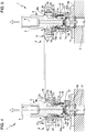
- number 1 indicates, as a whole, a quick-coupling safety joint, in particular a joint for medical applications, to connect, in a fluid-tight manner, two delivery ducts 2, 3 for a pressurised operative fluid, for example compressed air or gas.
- a pressurised operative fluid for example compressed air or gas.
- the joint 1 has a longitudinal axis A and comprises a grabbing member 4 according to the invention, which has a substantially cylindrical configuration with axis A and is designed to be connected to the duct 2, and a terminal 5, in particular a standard terminal (which is known and is not part of the invention), which also has a substantially cylindrical configuration, is connected to the duct 3 and is designed to be coupled inside the grabbing member 4, in a releasable manner, in a coupling condition.
- a grabbing member 4 according to the invention, which has a substantially cylindrical configuration with axis A and is designed to be connected to the duct 2, and a terminal 5, in particular a standard terminal (which is known and is not part of the invention), which also has a substantially cylindrical configuration, is connected to the duct 3 and is designed to be coupled inside the grabbing member 4, in a releasable manner, in a coupling condition.
- the terminal 5, which is only described in order to provide complete information that can help readers understand the features of the grabbing member 4, has a substantially tubular shape and comprises two tubular portions 6, 7 with a different diameter, which are joined to one another. More in particular, the portion 6 is connected to the duct 3, whereas the portion 7 defines a radial protuberance 7 of the terminal 5, which radially projects relative to the portion 6.
- the grabbing member 4 basically comprises a tubular main body 8 with axis A, which has a substantially cylindrical conformation and is fixed, for example by means of a threaded coupling, to the duct 2 in the area of an axially open end portion 8a of its.
- the main body 8 is configured to axially receive the terminal 5, so that it can be engaged, through an axially open end portion 8b of its, which is opposite the end portion 8a.
- the terminal 5 is configured to axially engage the main body 8 until it reaches an advanced coupling position, in which the duct 2 is fluidically connected to the duct 3, in the way described below.
- the grabbing member 4 comprises a valve element 10, in particular a slide valve, which is mounted so as to axially slide inside the main body 8, preferably coaxially to the axis A, and is movable between a closed position, in which it seals the duct 2, in a fluid-tight manner, from the surrounding environment, and an open position, in which it allows the pressurised operative fluid to flow out of the duct 2.
- a valve element 10 in particular a slide valve, which is mounted so as to axially slide inside the main body 8, preferably coaxially to the axis A, and is movable between a closed position, in which it seals the duct 2, in a fluid-tight manner, from the surrounding environment, and an open position, in which it allows the pressurised operative fluid to flow out of the duct 2.
- the grabbing member 4 comprises a helical spring 11 with axis A, which is housed inside the main body 8, in particular is operatively interposed between the main body 8 and the valve element 10, and exerts an axial force upon the valve element 10 in order to hold it in the closed position.
- the spring 11 pushes and holds, in the absence of opposing actions, the valve element 10 against a sealing element 12, for example an o-ring, so as to seal the duct 2 in a fluid-tight manner.
- the valve element 10 can be arranged in the open position through the interaction with the terminal 5: in use, the axial insertion of the terminal 5 into the main body 8 in its advanced coupling position ( figure 3 ) determines, through the interaction of an end surface 5a of the terminal 5 with an axial pin 10a of the valve element 10, a force that is opposite and predominant relative to the force exerted by the spring 11 so as to hold the valve element 10 in the open position.
- the terminal 5 arranged in its coupling position determines the opening of the fluidic connection between the duct 2 and the duct 3.
- the grabbing member 4 comprises first releasable stopping means 13, which are configured to constrain the terminal 5 in said advanced coupling position inside the main body 8, in which the terminal 5 exerts an opposite and predominant force, relative to the force exerted by the spring 11, upon the valve element in order to keep it in the open position.
- the first stopping means comprise a pair of bars 13, preferably cylindrical bars, which are arranged in respective transverse through slots 14 obtained in the main body 8 on diametrically opposite sides relative to the axis A and have axes that are parallel to one another and orthogonal to the axis A.
- the bars 3 can slide in the slots 14 from and to the axis A between:
- the bars 13 In the radially extracted position, the bars 13 have respective intermediate portions that partially project into the main body 8 so as to narrow the passage cross section thereof and, hence, define an axial abutment for the radial protuberance 7 of the terminal 5, which constrains the terminal 5 in the advanced coupling position.
- the bars 13 are arranged at a suitable axial distance from the pin 10a of the valve element 10.
- each slot 14 is delimited by relative lateral sides, which are oblique relative to the axis A and parallel to one another.
- the bars 13 are axially loaded towards the radially extracted position by a helical spring 15, which is wound around the main body 8 and is interposed between the bars 13 and an outer shoulder 16, which is fixed relative to the main body 8 and to the grabbing member 4.
- the bars 13 are conveniently arranged in a position axially upstream of the valve element 10, along the direction of insertion of the terminal 5 into the main body 8.
- the radial protuberance 7 exerts upon the bars 13 a force that is opposite and predominant relative to the force exerted upon them by the spring 15, and causes them to move from the extracted position to the retracted position.
- the grabbing member 4 conveniently comprises a drive assembly 17, preferably a manually-operated one, which is mounted so as to axially slide on the outer surface of the main body 8, is loaded by the spring 15 and is configured to release the first stopping means.
- the drive assembly 17 can axially be moved to an operative release position, in which it determines the release of the first stopping means.
- the drive assembly 17 can be operated so as to cause the movement of the bars from the extracted position 13 to the retracted position and, hence, to determine the release of the terminal 5 from the advanced coupling position.
- the drive assembly 17 comprises a ring nut 18 with axis A and a tubular sleeve 19 with axis A, which is fixed to the ring nut 18 and is operatively coupled to the spring 15 through a radial projection 19a.
- the spring 15 axially loads the sleeve 19 and, consequently, the ring nut 18 so as to hold them in a rest position, in which the spring 15 further loads the bars 13 in an axial direction.
- the terminal 5 which is pushed by the action of the spring 11 and by the pressure of the operative fluid acting upon the valve element 10 and for it does no longer strike against the bars 13, gets axially projected, in particular upward in figure 4 , and, hence, is removed from its advanced coupling position.
- the valve element 10 goes back, pushed by the spring 11, to its closed position and the fluidic connection between the duct 2 and the duct 3 is interrupted.
- the pressure (manually) exerted upon the ring nut 18 can be interrupted.
- the grabbing member 4 comprises second releasable stopping means 20, which are designed to cooperate with the terminal 5 in order to hold it, after the release of the first stopping means 13 and during the uncoupling of the terminal 5 from the main body 8, in a retracted safety position, in which the terminal 5 (still) is mechanically connected to the main body 8 and is separated from the valve element 10 so as to allow the latter to be arranged in the closed position.
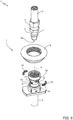
- the second stopping means comprise at least one blocking element 20, which defines an axial abutment for the terminal 5 in the retracted safety position and extends along a circumferential direction around the longitudinal axis A, so as to define an arc-shaped or half-moon shaped profile.
- the second stopping means comprise two blocking elements 20, which are radially opposite one another and are each configured to interact with the terminal 5 in the retracted safety position so as to define an axial abutment for the terminal 5 extending along the circumferential direction around the axis A.
- the blocking elements 20 are arranged on a same plane, which is orthogonal to the axis A.
- the blocking elements 20 are axially spaced apart from the bars 13, in particular are arranged axially upstream of the bars 13 relative to the direction of insertion of the terminal 5 into the main body 8.
- the blocking element 20 define an axial safety abutment in addition to the axial coupling abutment defined by the bars 13.
- the second stopping means comprise a plurality of blocking elements 20, which, in this case, are angularly equally spaced apart from one another around the axis A.
- the blocking element 20 is defined by an angular toroid portion arranged coaxial to the axis A.
- each blocking element 20 has a cross-section, in a radial direction relative to the axis A, having a closed-line perimeter including a first C-shaped portion 21 and a second C-shaped portion 22, which is radially more external than the first portion 21.
- the first portion 21 and the second portion 22 are connected to one another at the respective free ends and have respective concavities facing one another in the radial direction.
- the free end portions of the first portion 21 have an aperture which is different from, in particular smaller than, the aperture of the free end portions of the second portion 22, relative to the axial direction.
- the first portion 21 substantially has the shape of an ellipsis
- the portion 22 comprises, in turn, a central circular arc and two lateral straight segments defining the free end portions of the portion 22 itself.
- the perimeter of the aforesaid cross section further comprises a pair of first straight segments 23, which are axially opposite one another and each join the first portion 21 to the second portion 22 in the area of the free ends thereof, respectively.
- this conformation of the blocking element 20 is the one providing the best performances in terms of wear and resistance to the hits caused by the impact of the terminal 5 disengaged by means of the drive assembly 17 from the advanced coupling position to the retracted safety position.
- each blocking element 20 identifies, together with the terminal 5 and as long as the terminal 5, namely the radial protuberance 7, strikes against the blocking element 20, a contact area having a profile substantially shaped like an arc of an annulus.
- said contact area which is more extended compared to a punctual contact area, improves the performances of the terminal 5 and, hence, of the joint 1 in terms of wear and useful life.
- the drive assembly 17 arranged in its release position avoids a radial movement of the blocking elements 20 to constrain them, in a striking manner, against the terminal 5, namely against the radial protuberance 7 of the terminal 5, released by the first stopping means 13 in the retracted safety position.
- the grabbing member 4 comprises a radial shoulder element 24 for the blocking element 20, which can be moved, in particular can axially be moved, between:
- the shoulder element 24 is defined by a sleeve with axis A, which is operatively coupled to the drive assembly 17.
- the shoulder element 24 is operatively coupled to the ring nut 18 so that, when the drive assembly 17 is operated, namely when the ring nut 18 is axially moved to the operative rest position, the shoulder element 24 is moved, in particular axially moved, to the shoulder position.
- the shoulder element 24 comprises a radial projection 25, which is designed to cooperate with, in particular be axially pushed by, the ring nut 18 following an actuation thereof, so as to radially face, in its shoulder position, in particular so as to be in contact with, the second portion 22 of the respective blocking element 20.
- the second stopping means 20 are held in position, preventing the terminal 5 from violently coming out of the main body 8.
- the blocking elements 20 are capable of radially moving to the retracted release position following the extraction movement of the terminal 5 and pushed by the radial protuberance 7,, thus allowing the terminal 5 to be completely extracted from the main body 8.
- each blocking element 20 is housed in a suitable through slot 26, which is radially obtained in the main body 8.
- the blocking elements 20 are radially movable within the slots 26 during their radial movement between the retracted release position and the advanced abutment position.
- the blocking elements 20 partially engage the tubular body 8 in a radial direction so as to narrow the passage cross section thereof and, hence, define an axial abutment for the radial protuberance 7 of the terminal 5, which holds the terminal 5 in the retracted safety position.
- the blocking elements are completely housed (retracted) inside the slots 26, thus freeing the passage cross section of the main body 8 and allowing the terminal 5 to be extracted.
- each blocking element 20 During the radial movement of each blocking element 20, the respective segments 23 slide on the inner sides of the respective slot 26.
- each blocking element 20 is made of a plastic material, preferably a polymer, more preferably a thermoplastic polymer.
- this material further improves the performances in terms of wear and useful life of the terminal 5, since it at least partially absorbs hit forces, thus reducing the intensity thereof affecting the terminal 5.
- the terminal 5 is further advanced in an axial direction into the main body 8 and towards the valve element 10, until it reaches the advanced coupling position and determines the opening of the valve element 10 as described above as well as the fluidic connection between the duct 2 and the duct 3.
- the terminal 5 is constrained in this position by the bars 13, as shown in figure 3 .
- the terminal 5 can then be extracted from the main body 8 in a completely safe manner.
- an extended and non-punctual abutment surface is defined for the terminal 5.
- the pressure exerted upon the radial protuberance of the terminal 5 is smaller. This leads to a smaller wear of the component and, hence, to an extension of the useful life thereof.
- the blocking elements 20 are made of a plastic material, preferably a polymer, more preferably a thermoplastic polymer.
Landscapes
- Engineering & Computer Science (AREA)
- General Engineering & Computer Science (AREA)
- Mechanical Engineering (AREA)
- Quick-Acting Or Multi-Walled Pipe Joints (AREA)
Applications Claiming Priority (1)
| Application Number | Priority Date | Filing Date | Title |
|---|---|---|---|
| IT102020000006985A IT202000006985A1 (it) | 2020-04-02 | 2020-04-02 | Organo di presa per giunto ad innesto rapido di sicurezza |
Publications (2)
| Publication Number | Publication Date |
|---|---|
| EP3889486A1 true EP3889486A1 (de) | 2021-10-06 |
| EP3889486B1 EP3889486B1 (de) | 2024-05-29 |
Family
ID=70978465
Family Applications (1)
| Application Number | Title | Priority Date | Filing Date |
|---|---|---|---|
| EP21166813.2A Active EP3889486B1 (de) | 2020-04-02 | 2021-04-02 | Greifelement für schnellkuppelnde sicherheitsverbindung |
Country Status (2)
| Country | Link |
|---|---|
| EP (1) | EP3889486B1 (de) |
| IT (1) | IT202000006985A1 (de) |
Cited By (1)
| Publication number | Priority date | Publication date | Assignee | Title |
|---|---|---|---|---|
| CN114838223A (zh) * | 2022-03-25 | 2022-08-02 | 化生医疗科技有限公司 | 一种卡扣式气体终端组件 |
Families Citing this family (1)
| Publication number | Priority date | Publication date | Assignee | Title |
|---|---|---|---|---|
| CN116002604A (zh) * | 2023-01-04 | 2023-04-25 | 珠海凌达压缩机有限公司 | 加油装置 |
Citations (4)
| Publication number | Priority date | Publication date | Assignee | Title |
|---|---|---|---|---|
| DE2741512A1 (de) * | 1977-09-15 | 1979-04-05 | Kurt Schildmann | Schnellschlusskupplung |
| US5240023A (en) * | 1991-04-08 | 1993-08-31 | Gad Shelef | Safety hose coupler |
| EP1455131A1 (de) * | 2003-03-04 | 2004-09-08 | Pres-Block S.P.A. | Greiforgan für eine Sicherheitsschnellkupplung |
| EP2369214A1 (de) * | 2010-03-05 | 2011-09-28 | Faster S.P.A. | Mit einem Verschlusssystem mit ringförmigen Sektoren ausgerüstete Innengewindekupplung |
-
2020
- 2020-04-02 IT IT102020000006985A patent/IT202000006985A1/it unknown
-
2021
- 2021-04-02 EP EP21166813.2A patent/EP3889486B1/de active Active
Patent Citations (4)
| Publication number | Priority date | Publication date | Assignee | Title |
|---|---|---|---|---|
| DE2741512A1 (de) * | 1977-09-15 | 1979-04-05 | Kurt Schildmann | Schnellschlusskupplung |
| US5240023A (en) * | 1991-04-08 | 1993-08-31 | Gad Shelef | Safety hose coupler |
| EP1455131A1 (de) * | 2003-03-04 | 2004-09-08 | Pres-Block S.P.A. | Greiforgan für eine Sicherheitsschnellkupplung |
| EP2369214A1 (de) * | 2010-03-05 | 2011-09-28 | Faster S.P.A. | Mit einem Verschlusssystem mit ringförmigen Sektoren ausgerüstete Innengewindekupplung |
Cited By (2)
| Publication number | Priority date | Publication date | Assignee | Title |
|---|---|---|---|---|
| CN114838223A (zh) * | 2022-03-25 | 2022-08-02 | 化生医疗科技有限公司 | 一种卡扣式气体终端组件 |
| CN114838223B (zh) * | 2022-03-25 | 2023-06-30 | 化生医疗科技有限公司 | 一种卡扣式气体终端组件 |
Also Published As
| Publication number | Publication date |
|---|---|
| IT202000006985A1 (it) | 2021-10-02 |
| EP3889486B1 (de) | 2024-05-29 |
Similar Documents
| Publication | Publication Date | Title |
|---|---|---|
| EP3889486B1 (de) | Greifelement für schnellkuppelnde sicherheitsverbindung | |
| ES2762945T3 (es) | Aparato de desconexión rápida para herramientas modulares | |
| US4792115A (en) | Coupling with fusible actuator member | |
| EP0519759B1 (de) | Schnellkupplung für Fluide | |
| US4366945A (en) | Hose coupling with double lock | |
| US6279874B1 (en) | Coupling for hoses or the like | |
| US5056560A (en) | Quick disconnect couplings unthreaded refrigerant fitments | |
| US20140145430A1 (en) | Female quick-connect coupling element, and a quick-connect coupling incorporating such an element | |
| CN103562609B (zh) | 压缩空气联结器 | |
| US5048874A (en) | Quick coupling for interconnection of two high-pressure fluid conduits | |
| CN101378861B (zh) | 用于将套环型锻至外部有槽构件上的器具 | |
| US5950679A (en) | High pressure plug coupling | |
| CN106461142B (zh) | 用于增压流体的快装式耦合器 | |
| US3460801A (en) | Valved fluid coupling or conduit | |
| US4413846A (en) | Hose coupling | |
| JP2022518444A5 (de) | ||
| US8955823B2 (en) | Cam operated valve | |
| CA2736719C (en) | Cam operated valve | |
| ES2760986T3 (es) | Acoplamiento rápido | |
| US5323811A (en) | Fluid coupling with automatic sealing valves | |
| KR101858164B1 (ko) | 호스용 밸브 조립체 | |
| ES2741601T3 (es) | Acoplamiento de conexión rápida | |
| EP2867570B1 (de) | Schnellagierende steckkupplung zum fördern von flüssigkeiten unter druck | |
| EP1455131A1 (de) | Greiforgan für eine Sicherheitsschnellkupplung | |
| EP3879160B1 (de) | Universeller sicherheitskoppler für drucksysteme |
Legal Events
| Date | Code | Title | Description |
|---|---|---|---|
| PUAI | Public reference made under article 153(3) epc to a published international application that has entered the european phase |
Free format text: ORIGINAL CODE: 0009012 |
|
| STAA | Information on the status of an ep patent application or granted ep patent |
Free format text: STATUS: THE APPLICATION HAS BEEN PUBLISHED |
|
| AK | Designated contracting states |
Kind code of ref document: A1 Designated state(s): AL AT BE BG CH CY CZ DE DK EE ES FI FR GB GR HR HU IE IS IT LI LT LU LV MC MK MT NL NO PL PT RO RS SE SI SK SM TR |
|
| STAA | Information on the status of an ep patent application or granted ep patent |
Free format text: STATUS: REQUEST FOR EXAMINATION WAS MADE |
|
| 17P | Request for examination filed |
Effective date: 20220318 |
|
| RBV | Designated contracting states (corrected) |
Designated state(s): AL AT BE BG CH CY CZ DE DK EE ES FI FR GB GR HR HU IE IS IT LI LT LU LV MC MK MT NL NO PL PT RO RS SE SI SK SM TR |
|
| GRAP | Despatch of communication of intention to grant a patent |
Free format text: ORIGINAL CODE: EPIDOSNIGR1 |
|
| STAA | Information on the status of an ep patent application or granted ep patent |
Free format text: STATUS: GRANT OF PATENT IS INTENDED |
|
| INTG | Intention to grant announced |
Effective date: 20231120 |
|
| GRAS | Grant fee paid |
Free format text: ORIGINAL CODE: EPIDOSNIGR3 |
|
| P01 | Opt-out of the competence of the unified patent court (upc) registered |
Effective date: 20240313 |
|
| GRAA | (expected) grant |
Free format text: ORIGINAL CODE: 0009210 |
|
| STAA | Information on the status of an ep patent application or granted ep patent |
Free format text: STATUS: THE PATENT HAS BEEN GRANTED |
|
| AK | Designated contracting states |
Kind code of ref document: B1 Designated state(s): AL AT BE BG CH CY CZ DE DK EE ES FI FR GB GR HR HU IE IS IT LI LT LU LV MC MK MT NL NO PL PT RO RS SE SI SK SM TR |
|
| REG | Reference to a national code |
Ref country code: CH Ref legal event code: EP |
|
| REG | Reference to a national code |
Ref country code: IE Ref legal event code: FG4D |
|
| REG | Reference to a national code |
Ref country code: DE Ref legal event code: R096 Ref document number: 602021013710 Country of ref document: DE |
|
| REG | Reference to a national code |
Ref country code: LT Ref legal event code: MG9D |
|
| REG | Reference to a national code |
Ref country code: NL Ref legal event code: MP Effective date: 20240529 |
|
| PG25 | Lapsed in a contracting state [announced via postgrant information from national office to epo] |
Ref country code: IS Free format text: LAPSE BECAUSE OF FAILURE TO SUBMIT A TRANSLATION OF THE DESCRIPTION OR TO PAY THE FEE WITHIN THE PRESCRIBED TIME-LIMIT Effective date: 20240929 |
|
| PG25 | Lapsed in a contracting state [announced via postgrant information from national office to epo] |
Ref country code: BG Free format text: LAPSE BECAUSE OF FAILURE TO SUBMIT A TRANSLATION OF THE DESCRIPTION OR TO PAY THE FEE WITHIN THE PRESCRIBED TIME-LIMIT Effective date: 20240529 |
|
| PG25 | Lapsed in a contracting state [announced via postgrant information from national office to epo] |
Ref country code: FI Free format text: LAPSE BECAUSE OF FAILURE TO SUBMIT A TRANSLATION OF THE DESCRIPTION OR TO PAY THE FEE WITHIN THE PRESCRIBED TIME-LIMIT Effective date: 20240529 Ref country code: HR Free format text: LAPSE BECAUSE OF FAILURE TO SUBMIT A TRANSLATION OF THE DESCRIPTION OR TO PAY THE FEE WITHIN THE PRESCRIBED TIME-LIMIT Effective date: 20240529 |
|
| PG25 | Lapsed in a contracting state [announced via postgrant information from national office to epo] |
Ref country code: GR Free format text: LAPSE BECAUSE OF FAILURE TO SUBMIT A TRANSLATION OF THE DESCRIPTION OR TO PAY THE FEE WITHIN THE PRESCRIBED TIME-LIMIT Effective date: 20240830 |
|
| REG | Reference to a national code |
Ref country code: AT Ref legal event code: UEP Ref document number: 1690923 Country of ref document: AT Kind code of ref document: T Effective date: 20240529 |
|
| PG25 | Lapsed in a contracting state [announced via postgrant information from national office to epo] |
Ref country code: ES Free format text: LAPSE BECAUSE OF FAILURE TO SUBMIT A TRANSLATION OF THE DESCRIPTION OR TO PAY THE FEE WITHIN THE PRESCRIBED TIME-LIMIT Effective date: 20240529 |
|
| PG25 | Lapsed in a contracting state [announced via postgrant information from national office to epo] |
Ref country code: PL Free format text: LAPSE BECAUSE OF FAILURE TO SUBMIT A TRANSLATION OF THE DESCRIPTION OR TO PAY THE FEE WITHIN THE PRESCRIBED TIME-LIMIT Effective date: 20240529 |
|
| PG25 | Lapsed in a contracting state [announced via postgrant information from national office to epo] |
Ref country code: LV Free format text: LAPSE BECAUSE OF FAILURE TO SUBMIT A TRANSLATION OF THE DESCRIPTION OR TO PAY THE FEE WITHIN THE PRESCRIBED TIME-LIMIT Effective date: 20240529 |
|
| PG25 | Lapsed in a contracting state [announced via postgrant information from national office to epo] |
Ref country code: PL Free format text: LAPSE BECAUSE OF FAILURE TO SUBMIT A TRANSLATION OF THE DESCRIPTION OR TO PAY THE FEE WITHIN THE PRESCRIBED TIME-LIMIT Effective date: 20240529 Ref country code: NO Free format text: LAPSE BECAUSE OF FAILURE TO SUBMIT A TRANSLATION OF THE DESCRIPTION OR TO PAY THE FEE WITHIN THE PRESCRIBED TIME-LIMIT Effective date: 20240829 Ref country code: LV Free format text: LAPSE BECAUSE OF FAILURE TO SUBMIT A TRANSLATION OF THE DESCRIPTION OR TO PAY THE FEE WITHIN THE PRESCRIBED TIME-LIMIT Effective date: 20240529 Ref country code: IS Free format text: LAPSE BECAUSE OF FAILURE TO SUBMIT A TRANSLATION OF THE DESCRIPTION OR TO PAY THE FEE WITHIN THE PRESCRIBED TIME-LIMIT Effective date: 20240929 Ref country code: HR Free format text: LAPSE BECAUSE OF FAILURE TO SUBMIT A TRANSLATION OF THE DESCRIPTION OR TO PAY THE FEE WITHIN THE PRESCRIBED TIME-LIMIT Effective date: 20240529 Ref country code: GR Free format text: LAPSE BECAUSE OF FAILURE TO SUBMIT A TRANSLATION OF THE DESCRIPTION OR TO PAY THE FEE WITHIN THE PRESCRIBED TIME-LIMIT Effective date: 20240830 Ref country code: FI Free format text: LAPSE BECAUSE OF FAILURE TO SUBMIT A TRANSLATION OF THE DESCRIPTION OR TO PAY THE FEE WITHIN THE PRESCRIBED TIME-LIMIT Effective date: 20240529 Ref country code: ES Free format text: LAPSE BECAUSE OF FAILURE TO SUBMIT A TRANSLATION OF THE DESCRIPTION OR TO PAY THE FEE WITHIN THE PRESCRIBED TIME-LIMIT Effective date: 20240529 Ref country code: BG Free format text: LAPSE BECAUSE OF FAILURE TO SUBMIT A TRANSLATION OF THE DESCRIPTION OR TO PAY THE FEE WITHIN THE PRESCRIBED TIME-LIMIT Effective date: 20240529 Ref country code: RS Free format text: LAPSE BECAUSE OF FAILURE TO SUBMIT A TRANSLATION OF THE DESCRIPTION OR TO PAY THE FEE WITHIN THE PRESCRIBED TIME-LIMIT Effective date: 20240829 |
|
| PG25 | Lapsed in a contracting state [announced via postgrant information from national office to epo] |
Ref country code: NL Free format text: LAPSE BECAUSE OF FAILURE TO SUBMIT A TRANSLATION OF THE DESCRIPTION OR TO PAY THE FEE WITHIN THE PRESCRIBED TIME-LIMIT Effective date: 20240529 |
|
| PG25 | Lapsed in a contracting state [announced via postgrant information from national office to epo] |
Ref country code: NL Free format text: LAPSE BECAUSE OF FAILURE TO SUBMIT A TRANSLATION OF THE DESCRIPTION OR TO PAY THE FEE WITHIN THE PRESCRIBED TIME-LIMIT Effective date: 20240529 |
|
| PG25 | Lapsed in a contracting state [announced via postgrant information from national office to epo] |
Ref country code: DK Free format text: LAPSE BECAUSE OF FAILURE TO SUBMIT A TRANSLATION OF THE DESCRIPTION OR TO PAY THE FEE WITHIN THE PRESCRIBED TIME-LIMIT Effective date: 20240529 |
|
| PG25 | Lapsed in a contracting state [announced via postgrant information from national office to epo] |
Ref country code: EE Free format text: LAPSE BECAUSE OF FAILURE TO SUBMIT A TRANSLATION OF THE DESCRIPTION OR TO PAY THE FEE WITHIN THE PRESCRIBED TIME-LIMIT Effective date: 20240529 |
|
| PG25 | Lapsed in a contracting state [announced via postgrant information from national office to epo] |
Ref country code: CZ Free format text: LAPSE BECAUSE OF FAILURE TO SUBMIT A TRANSLATION OF THE DESCRIPTION OR TO PAY THE FEE WITHIN THE PRESCRIBED TIME-LIMIT Effective date: 20240529 |
|
| PG25 | Lapsed in a contracting state [announced via postgrant information from national office to epo] |
Ref country code: SK Free format text: LAPSE BECAUSE OF FAILURE TO SUBMIT A TRANSLATION OF THE DESCRIPTION OR TO PAY THE FEE WITHIN THE PRESCRIBED TIME-LIMIT Effective date: 20240529 Ref country code: RO Free format text: LAPSE BECAUSE OF FAILURE TO SUBMIT A TRANSLATION OF THE DESCRIPTION OR TO PAY THE FEE WITHIN THE PRESCRIBED TIME-LIMIT Effective date: 20240529 |
|
| PG25 | Lapsed in a contracting state [announced via postgrant information from national office to epo] |
Ref country code: SM Free format text: LAPSE BECAUSE OF FAILURE TO SUBMIT A TRANSLATION OF THE DESCRIPTION OR TO PAY THE FEE WITHIN THE PRESCRIBED TIME-LIMIT Effective date: 20240529 |
|
| PG25 | Lapsed in a contracting state [announced via postgrant information from national office to epo] |
Ref country code: SM Free format text: LAPSE BECAUSE OF FAILURE TO SUBMIT A TRANSLATION OF THE DESCRIPTION OR TO PAY THE FEE WITHIN THE PRESCRIBED TIME-LIMIT Effective date: 20240529 Ref country code: SK Free format text: LAPSE BECAUSE OF FAILURE TO SUBMIT A TRANSLATION OF THE DESCRIPTION OR TO PAY THE FEE WITHIN THE PRESCRIBED TIME-LIMIT Effective date: 20240529 Ref country code: RO Free format text: LAPSE BECAUSE OF FAILURE TO SUBMIT A TRANSLATION OF THE DESCRIPTION OR TO PAY THE FEE WITHIN THE PRESCRIBED TIME-LIMIT Effective date: 20240529 Ref country code: EE Free format text: LAPSE BECAUSE OF FAILURE TO SUBMIT A TRANSLATION OF THE DESCRIPTION OR TO PAY THE FEE WITHIN THE PRESCRIBED TIME-LIMIT Effective date: 20240529 Ref country code: DK Free format text: LAPSE BECAUSE OF FAILURE TO SUBMIT A TRANSLATION OF THE DESCRIPTION OR TO PAY THE FEE WITHIN THE PRESCRIBED TIME-LIMIT Effective date: 20240529 Ref country code: CZ Free format text: LAPSE BECAUSE OF FAILURE TO SUBMIT A TRANSLATION OF THE DESCRIPTION OR TO PAY THE FEE WITHIN THE PRESCRIBED TIME-LIMIT Effective date: 20240529 |
|
| REG | Reference to a national code |
Ref country code: DE Ref legal event code: R097 Ref document number: 602021013710 Country of ref document: DE |
|
| PLBE | No opposition filed within time limit |
Free format text: ORIGINAL CODE: 0009261 |
|
| STAA | Information on the status of an ep patent application or granted ep patent |
Free format text: STATUS: NO OPPOSITION FILED WITHIN TIME LIMIT |
|
| PG25 | Lapsed in a contracting state [announced via postgrant information from national office to epo] |
Ref country code: SI Free format text: LAPSE BECAUSE OF FAILURE TO SUBMIT A TRANSLATION OF THE DESCRIPTION OR TO PAY THE FEE WITHIN THE PRESCRIBED TIME-LIMIT Effective date: 20240529 |
|
| 26N | No opposition filed |
Effective date: 20250303 |
|
| PGFP | Annual fee paid to national office [announced via postgrant information from national office to epo] |
Ref country code: DE Payment date: 20250428 Year of fee payment: 5 |
|
| PGFP | Annual fee paid to national office [announced via postgrant information from national office to epo] |
Ref country code: IT Payment date: 20250404 Year of fee payment: 5 |
|
| PGFP | Annual fee paid to national office [announced via postgrant information from national office to epo] |
Ref country code: AT Payment date: 20250721 Year of fee payment: 5 |
|
| PG25 | Lapsed in a contracting state [announced via postgrant information from national office to epo] |
Ref country code: SE Free format text: LAPSE BECAUSE OF FAILURE TO SUBMIT A TRANSLATION OF THE DESCRIPTION OR TO PAY THE FEE WITHIN THE PRESCRIBED TIME-LIMIT Effective date: 20240529 |
|
| REG | Reference to a national code |
Ref country code: CH Ref legal event code: H13 Free format text: ST27 STATUS EVENT CODE: U-0-0-H10-H13 (AS PROVIDED BY THE NATIONAL OFFICE) Effective date: 20251125 |
|
| PG25 | Lapsed in a contracting state [announced via postgrant information from national office to epo] |
Ref country code: LU Free format text: LAPSE BECAUSE OF NON-PAYMENT OF DUE FEES Effective date: 20250402 |
|
| PG25 | Lapsed in a contracting state [announced via postgrant information from national office to epo] |
Ref country code: MC Free format text: LAPSE BECAUSE OF FAILURE TO SUBMIT A TRANSLATION OF THE DESCRIPTION OR TO PAY THE FEE WITHIN THE PRESCRIBED TIME-LIMIT Effective date: 20240529 |
|
| GBPC | Gb: european patent ceased through non-payment of renewal fee |
Effective date: 20250402 |
|
| REG | Reference to a national code |
Ref country code: BE Ref legal event code: MM Effective date: 20250430 |
|
| PG25 | Lapsed in a contracting state [announced via postgrant information from national office to epo] |
Ref country code: GB Free format text: LAPSE BECAUSE OF NON-PAYMENT OF DUE FEES Effective date: 20250402 |
|
| PG25 | Lapsed in a contracting state [announced via postgrant information from national office to epo] |
Ref country code: FR Free format text: LAPSE BECAUSE OF NON-PAYMENT OF DUE FEES Effective date: 20250430 |
|
| PG25 | Lapsed in a contracting state [announced via postgrant information from national office to epo] |
Ref country code: BE Free format text: LAPSE BECAUSE OF NON-PAYMENT OF DUE FEES Effective date: 20250430 |
|
| PG25 | Lapsed in a contracting state [announced via postgrant information from national office to epo] |
Ref country code: CH Free format text: LAPSE BECAUSE OF NON-PAYMENT OF DUE FEES Effective date: 20250430 |
|
| PG25 | Lapsed in a contracting state [announced via postgrant information from national office to epo] |
Ref country code: IE Free format text: LAPSE BECAUSE OF NON-PAYMENT OF DUE FEES Effective date: 20250402 |