EP3889552A1 - Durchflussmessgerät - Google Patents
Durchflussmessgerät Download PDFInfo
- Publication number
- EP3889552A1 EP3889552A1 EP20168003.0A EP20168003A EP3889552A1 EP 3889552 A1 EP3889552 A1 EP 3889552A1 EP 20168003 A EP20168003 A EP 20168003A EP 3889552 A1 EP3889552 A1 EP 3889552A1
- Authority
- EP
- European Patent Office
- Prior art keywords
- flow
- ultrasonic
- ultrasonic transducer
- measuring
- paths
- Prior art date
- Legal status (The legal status is an assumption and is not a legal conclusion. Google has not performed a legal analysis and makes no representation as to the accuracy of the status listed.)
- Granted
Links
Images

Classifications
-
- G—PHYSICS
- G01—MEASURING; TESTING
- G01F—MEASURING VOLUME, VOLUME FLOW, MASS FLOW OR LIQUID LEVEL; METERING BY VOLUME
- G01F1/00—Measuring the volume flow or mass flow of fluid or fluent solid material wherein the fluid passes through a meter in a continuous flow
- G01F1/66—Measuring the volume flow or mass flow of fluid or fluent solid material wherein the fluid passes through a meter in a continuous flow by measuring frequency, phase shift or propagation time of electromagnetic or other waves, e.g. using ultrasonic flowmeters
-
- G—PHYSICS
- G01—MEASURING; TESTING
- G01F—MEASURING VOLUME, VOLUME FLOW, MASS FLOW OR LIQUID LEVEL; METERING BY VOLUME
- G01F1/00—Measuring the volume flow or mass flow of fluid or fluent solid material wherein the fluid passes through a meter in a continuous flow
- G01F1/66—Measuring the volume flow or mass flow of fluid or fluent solid material wherein the fluid passes through a meter in a continuous flow by measuring frequency, phase shift or propagation time of electromagnetic or other waves, e.g. using ultrasonic flowmeters
- G01F1/667—Arrangements of transducers for ultrasonic flowmeters; Circuits for operating ultrasonic flowmeters
-
- G—PHYSICS
- G01—MEASURING; TESTING
- G01F—MEASURING VOLUME, VOLUME FLOW, MASS FLOW OR LIQUID LEVEL; METERING BY VOLUME
- G01F1/00—Measuring the volume flow or mass flow of fluid or fluent solid material wherein the fluid passes through a meter in a continuous flow
- G01F1/66—Measuring the volume flow or mass flow of fluid or fluent solid material wherein the fluid passes through a meter in a continuous flow by measuring frequency, phase shift or propagation time of electromagnetic or other waves, e.g. using ultrasonic flowmeters
- G01F1/662—Constructional details
Definitions
- the invention relates to a flow measuring device based on ultrasound.
- a Doppler method the frequency shift, which varies depending on the flow velocity, of an ultrasonic signal reflected within the flowing fluid is evaluated.
- a differential transit time method a pair of ultrasonic transducers are mounted on the circumference of the pipeline with a mutual offset in the longitudinal direction, which alternately emit and register ultrasonic signals transversely to the flow along the measuring path spanned between the ultrasonic transducers.
- the ultrasonic signals transported by the fluid are accelerated or decelerated by the flow, depending on the direction of travel.
- the resulting difference in transit time is calculated using geometric variables to form an average flow rate of the fluid.
- the volume flow or flow rate results from the cross-sectional area.
- the ultrasonic transducers used to generate the ultrasound must couple the ultrasound into the fluid.
- a common solution consists in protruding the ultrasonic transducers into the line with direct contact with the fluid permit.
- the disadvantages are a disruption of the flow and thus inaccurate measurement results, direct contact with the fluid and its pressure and temperature, and possible deposits of impurities from the fluid.
- phased-array consists of individual ultrasonic transducers arranged in an array, which together emit an ultrasonic signal in superposition, the direction of which can be changed by changing the individual phases of the individual ultrasonic transducers.
- phased-array ultrasonic transducer units are inserted into openings in a flow channel and are then as flush as possible with the pipe wall and, depending on the control, can emit ultrasonic signals at different angles. As stated in the doctoral thesis, this allows a single pair of phased array ultrasonic transducer units to replace multiple pairs of traditional ultrasonic transducers, as shown in FIG Figure 1.1 the thesis is presented.
- phased-array ultrasonic transducer units are also disclosed in, for example Kang, Lei, Feeney, Andrew, Su, Riliang, Lines, David, Jäger, Axel, Wang, Han, Arnaudov, Yavor Emilov, Ramadas, Sivaram Nishal, Kupnik, Mario and Dixon, Steve M. (2017) Two-dimensional flexural ultrasonic phased array for flow measurement.
- IUS 2017 IEEE International Ultrasonics Symposium
- Washington, DC, USA 6-9 Sep 2017. Published in: 2017 IEEE International: Ultrasonics Symposium (IUS) ISSN 1948-5727 .
- the phased-array ultrasonic transducer units are used to compensate for the drifting effect at high flow velocities.
- the object of the invention is to provide an improved device for measuring the flow of a fluid, with which the aforementioned disadvantages in particular can be avoided, that is to say to provide high measurement accuracy with good signal quality using secant paths.
- the ultrasonic transducer units are at an installation angle which is between 20 ° and 140 °.
- the installation angle is to be understood as the angle between the two ultrasonic transducer units that results when looking in the longitudinal direction of the pipeline and looking at the relative position of the ultrasonic transducer units on the pipe circumference.
- An installation angle of 180 ° would correspond to a diametrical installation.
- An installation angle of 0 ° corresponds to the arrangement as shown in Figure 1.1 the doctoral thesis mentioned at the beginning is shown.
- the installation angle is in particular between 30 ° and 50 °.
- r / R is between 0.3 and 0.65 for the path sections, where R is the pipe diameter and r is the shortest distance of a path section to the center point. Then the measuring paths with their path sections are particularly favorable in order to sensibly scan the flow. They are off-center but not too close to the edge. The paths then also lie approximately on Gaussian nodes. This is advantageous because in the Gaussian node the flow profile does not change with the speed of the fluid. Overall, this results in a higher measurement accuracy.
- Measurement paths with more than five reflections do not provide any added value, because many of the possible measurement paths with more than five reflections cannot be used sensibly, since their path sections, for example, along the edge of the pipe are located or are too much in the middle and therefore run almost diametrically.
- a flow measuring device 10 according to the prior art is shown for the general explanation of the function of a generic flow measuring device.
- the flow measuring device 10 comprises a measuring sensor 12, which has a pipe 14 for the fluid with a pipe wall 16.
- the fluid, a gas or a liquid flowing through the conduit 14 is in Fig. 1 shown with a broad arrow 18 and flows in the z direction along a longitudinal direction 26 of the pipeline 14.
- the flow measuring device 10 also has two ultrasonic transducers 20 and 22 which define a measuring path 24 between them in the pipeline 14.
- the ultrasonic transducers 20 and 22 are arranged offset in the flow direction z, that is to say they are spaced apart in the longitudinal direction 26 of the pipeline 14. As a result, the measuring path 24 is not orthogonal to the flow direction z, but at an angle ⁇ .
- Each of the ultrasonic transducer units 20 and 22 can work as a transmitter or receiver and is controlled by a control and evaluation unit 28.
- the length L of the measuring path 24 in the fluid medium results from the angle ⁇ and the pipe diameter D.
- Ultrasonic signals that are sent and received as ultrasonic wave packets on the measuring path 24 in opposite directions have a component in the direction of the flow direction z and another time against the flow direction z and are thus accelerated with the flow 18 or decelerated against the flow 18 .
- the flow rate can then be calculated using the pipe cross section and the flow velocity v of the fluid 18.
- the flow measuring device 110 which is shown in FIG Figs. 2 and 3 is shown very schematically. It also has a measuring sensor 112 with a pipe 114 and two ultrasonic transducer units 120 and 122 in a pipe wall 116 and a control and evaluation unit 128.
- the ultrasonic transducer units 120 and 122 are not “simple" ultrasonic transducers, but are designed as phased-array ultrasonic transducer units.
- a two-dimensional array of individually controllable ultrasonic transducers 123 are controlled by the control and evaluation unit 128 to emit an ultrasonic packet so that they each have a phase offset from one another, the phase offset being selected so that the superposition of the ultrasonic waves resulting therefrom leads to an ultrasonic wave packet that runs along a certain measurement path 124 moved.
- the position of the measuring path 124 is therefore determined by the phase offset and should be aligned in such a way that the ultrasonic wave packet reaches the other ultrasonic transducer unit.
- the invention lies essentially in the positioning of the two ultrasonic transducer units 120 and 122 and the choice of the possible measurement paths 124.
- an installation angle ⁇ is defined for the purposes of this description.
- the installation angle ⁇ is to be understood as the angle between the two ultrasonic transducer units 120 and 122 that results when looking in the longitudinal direction along the central axis 126 of the pipeline 114 and looking at the relative position of the ultrasonic transducer units 120 and 122 on the pipe circumference ( Fig. 2 ). In other words, this is the angle ⁇ which the two connections between ultrasonic transducer 120 or 122 and central axis 126 enclose in the longitudinal direction view.
- An installation angle of 180 ° would correspond to a diametrical installation.
- an installation angle ⁇ of 90 ° is shown.
- the ultrasonic transducer units 120 and 122 are at an installation angle which is between 20 ° and 140 ° and in particular between 30 ° and 50 °.
- the ultrasonic signals arrive directly from one ultrasonic transducer unit 120 or 122 to the other ultrasonic transducer unit 122 or 120.
- This direct measuring path 124-0 therefore does not contain any reflection on the pipe wall 116.
- This is also intended by the addition "-0" may be expressed to the reference number.
- the ultrasonic signals experience a reflection at a point 130 on the pipe wall 116 (also expressed by the addition “-1”).
- the measurement path 124-1 is divided into two path sections 124-1a and 124-1b.
- the two Path sections 124-1a and 124-1b are of equal length, even if this is in the plane of the drawing of the actually three-dimensional arrangement of the Fig. 3 looks different.
- a path section, here 124-1a or 124-1b, is always that part of a measurement path, here 124, on which the ultrasound can propagate in a straight line without hindrance.
- Possible measurement paths 124 are in Fig. 5 shown in simplified form. These are measurement paths with 0 to 5 reflections.
- the measurement paths 124-0 with no reflection and 124-1 with a reflection and path sections 124-1a and 124-1b were described above with reference to FIG Figs. 2 and 3 explained.
- N + 1 alternatives are always possible for the measurement path.
- These alternative paths are marked with capital letters A to F.
- Measurement paths with more than five reflections do not provide any added value, because many of the possible measurement paths with more than five reflections cannot be used meaningfully because their path sections are located, for example, along the edge of the pipe (as in Fig. 5 already recognizable for measuring path 124-5 in alternative F) or are too much in the middle and therefore run almost diametrically (as measuring path 124-5 in alternative C shows a tendency). If the measurement paths remain within the indicated limits, the path sections of these measurement paths 124 lie in sensible and different areas of the cross section, so that the flow through the cross section of the pipeline 114 is better recorded.
Landscapes
- Physics & Mathematics (AREA)
- Electromagnetism (AREA)
- Fluid Mechanics (AREA)
- General Physics & Mathematics (AREA)
- Measuring Volume Flow (AREA)
Abstract
Description
- Die Erfindung betrifft ein Durchflussmessgerät auf Ultraschallbasis.
- Für die Bestimmung der Strömungsgeschwindigkeit oder des Durchflusses auf Ultraschallbasis sind unterschiedliche Messprinzipien bekannt. Bei einem Dopplerverfahren wird die je nach Strömungsgeschwindigkeit unterschiedliche Frequenzverschiebung eines innerhalb des strömenden Fluid reflektierten Ultraschallsignals ausgewertet. Bei einem Differenzlaufzeitverfahren wird ein Paar Ultraschallwandler am Umfang der Rohrleitung mit einem gegenseitigen Versatz in Längsrichtung montiert, die quer zu der Strömung entlang des zwischen den Ultraschallwandlern aufgespannten Messpfades wechselseitig Ultraschallsignale aussenden und registrieren. Die durch das Fluid transportierten Ultraschallsignale werden je nach Laufrichtung durch die Strömung beschleunigt oder abgebremst. Die resultierende Laufzeitdifferenz wird mit geometrischen Größen zu einer mittleren Strömungsgeschwindigkeit des Fluids verrechnet. Mit der Querschnittsfläche ergibt sich daraus der Volumenstrom oder Durchfluss. Für genauere Messungen können auch mehrere Messpfade mit jeweils einem Paar Ultraschallwandler vorgesehen sein, um einen Strömungsquerschnitt an mehr als einem Punkt zu erfassen. Für eine hohe Messgenauigkeit bei unsymmetrischen Geschwindigkeitsverteilungen über dem Strömungsquerschnitt, sind mehrere Messpfade erforderlich, die nicht durch die Rohrachse verlaufen, so genannte nicht-diametrale Messpfade bzw. Sekantenpfade.
- Die zur Erzeugung des Ultraschalls eingesetzten Ultraschallwandler müssen den Ultraschall in das Fluid einkoppeln. Eine verbreitete Lösung besteht darin, die Ultraschallwandler mit direktem Kontakt zum Fluid in die Leitung hineinragen zu lassen. Die Nachteile sind eine Störung der Strömung und damit ungenaue Messergebnisse, ein direkter Kontakt mit dem Fluid und dessen Druck und Temperatur und mögliche Ablagerungen von Verunreinigungen aus dem Fluid.
- Grundsätzlich sind auch Techniken bekannt, bei denen die Innenwand vollständig geschlossen bleibt, indem mittels der sogenannten Clamp-On-Montage Ultraschallwandler von außen an der Leitung befestigt werden und der Ultraschall dann nachteilig durch die Rohrwand in das Medium eindringen muss.
- Aus der Doktorarbeit "Development of piezoelectric and electrodynamic flexural transducers for air-coupled ultrasonics" von Tobias Eriksson, Univ. of Warwick, Sept. 2016, herunterladbar unter https://pugwash.lib.warwick.ac.uk/record=b3084015∼S15 ist der Einsatz von sogenannten "phased-array" Ultraschallwandlereinheiten bekannt. Ein "phased-array" besteht aus einzelnen, in einem Array angeordneten Ultraschallwandlern, die zusammen in Überlagerung ein Ultraschallsignal abgeben, dessen Abstrahlrichtung durch Änderung der einzelnen Phasen der einzelnen Ultraschallwandler änderbar ist. Diese "phased-array" Ultraschallwandlereinheiten werden in Öffnungen eines Strömungskanals eingesetzt und sind dann möglichst bündig mit der Rohrwand und können je nach Ansteuerung Ultraschallsignale in verschiedene Winkel abstrahlen. Wie in der Doktorarbeit ausgeführt, kann dadurch ein einziges Paar von phased-array-Ultraschallwandlereinheiten mehrere Paare von traditionellen Ultraschallwandlern ersetzen, wie dies in
Figur 1.1 der Doktorarbeit dargestellt ist. - Eine Anwendung solcher phased-array Ultraschallwandlereinheiten ist beispielsweise auch offenbart in Kang, Lei, Feeney, Andrew, Su, Riliang, Lines, David, Jäger, Axel, Wang, Han, Arnaudov, Yavor Emilov, Ramadas, Sivaram Nishal, Kupnik, Mario and Dixon, Steve M. (2017) Two-dimensional flexural ultrasonic phased-array for flow measurement. In: 2017 IEEE International Ultrasonics Symposium (IUS), Washington, DC, USA, 6-9 Sep 2017. Published in: 2017 IEEE International: Ultrasonics Symposium (IUS) ISSN 1948-5727. Hier werden die phased-array Ultraschallwandlereinheiten verwendet, um den Verwehungseffekt bei hohen Strömungsgeschwindigkeiten zu kompensieren.
- Allerdings werden in Zusammenhang mit phased-array Ultraschallwandlereinheiten nur diametrale Messpfade, die durch die Rohrachse verlaufen, offenbart. Bei nicht axialsymmetrischen Strömungsprofilen ergeben diametrale Messpfade ungenaue Messwerte, da das Strömungsprofil nur unzureichend über den Querschnitt erfasst wird.
- Ausgehend von diesem Stand der Technik ist es Aufgabe der Erfindung, eine verbesserte Vorrichtung zur Messung des Durchflusses eines Fluids bereitzustellen, mit der insbesondere die vorgenannten Nachteile vermieden werden können, also unter Verwendung von Sekantenpfaden eine hohe Messgenauigkeit mit guter Signalqualität zu liefern.
- Diese Aufgabe wird gelöst durch ein Durchflussmessgerät zur Messung des Durchflusses eines Fluids durch eine Rohrleitung mit den Merkmalen des Anspruchs 1.
- Das erfindungsgemäße Durchflussmessgerät umfasst
- einen Messaufnehmer, der eine Rohrleitung für das Fluid aufweist,
- zwei, in Längsrichtung der Rohrleitung beabstandete phased-array Ultraschallwandlereinheiten, die Ultraschallsignale in verschiedene Winkel abstrahlen und empfangen können,
- eine Steuer- und Auswerteeinheit zur Ansteuerung der Ultraschallwandlereinheiten und Auswertung der empfangenen Ultraschallsignale und Bestimmen des Durchflusses unter Verwendung der Laufzeit der Ultraschallsignale auf den Messpfaden,
- wobei die Ultraschallwandlereinheiten zwischen sich je nach Winkel der abgestrahlten Ultraschallsignale wenigstens zwei Messpfade definieren, auf denen die Ultraschallsignale von einer zur anderen Ultraschallwandlereinheit gelangen,
- wobei wenigstens einer der Messpfade wenigstens eine Reflexion an einer Rohrwand der Rohrleitung aufweist und durch die Reflexion bzw. Reflexionen Pfadabschnitte definiert sind. Ein Pfadabschnitt ist also immer der Teil eines Messpfades, auf dem sich der Ultraschall ungehindert geradlinig ausbreiten kann.
- Erfindungsgemäß liegen die Ultraschallwandlereinheiten in einem Einbauwinkel, der zwischen 20° und 140° liegt.
- Unter Einbauwinkel ist der Winkel zwischen den beiden Ultraschallwandlereinheiten zu verstehen, der sich ergibt, wenn man in Längsrichtung der Rohrleitung schaut und die relative Lage der Ultraschallwandlereinheiten auf dem Rohrumfang zueinander anschaut. Einem Einbauwinkel von 180° würde einer diametralen Montage entsprechen. Einem Einbauwinkel von 0° entspricht der Anordnung wie sie in
Figur 1.1 der eingangs erwähnten Doktorarbeit gezeigt ist. - Mit der erfindungsgemäßen Anordnung sind verschiedene Messpfade mit nur zwei Ultraschallwandlereinheiten möglich, wobei diese Messpfade, bzw. die Pfadabschnitte dieser Messpfade, in sinnvollen und unterschiedlichen Bereichen des Querschnitts liegen, so dass der Fluss über den Querschnitt der Rohrleitung besser erfasst wird.
- Dabei haben die Erfinder herausgefunden, dass es besonders vorteilhaft ist, wenn der Einbauwinkel insbesondere zwischen 30° und 50° liegt.
- Besonders vorteilhaft ist, wenn für die Pfadabschnitte gilt, das r/R zwischen 0,3 und 0,65 liegt, wobei R der Rohrdurchmesser ist und r der kürzeste Abstand eines Pfadabschnittes zum Mittelpunkt ist. Dann liegen die Messpfade mit ihren Pfadabschnitten besonders günstig, um die Strömung sinnvoll abzutasten. Sie liegen außermittig aber auch nicht zu nahe am Rand. Die Pfade liegen dann auch näherungsweise auf Gaußschen Knoten. Das ist vorteilhaft, denn im Gaußschen Knoten ändert sich das Strömungsprofil nicht mit der Geschwindigkeit des Fluids. Insgesamt ergibt das eine höhere Messgenauigkeit.
- In vorteilhafter Weiterbildung der Erfindung liegen nicht mehr als fünf Reflexionen pro Messpfad vor. Messpfade mit mehr als fünf Reflexionen liefern keinen Mehrwert, denn viele der möglichen Messpfade mit mehr als fünf Reflexionen sind nicht sinnvoll verwendbar, da deren Pfadabschnitte beispielsweise entlang des Randes des Rohres gelegen sind oder zu sehr in der Mitte liegen und daher fast schon diametral verlaufen.
- Im Folgenden wird die Erfindung anhand von Ausführungsbeispielen unter Bezugnahme auf die Zeichnung im Einzelnen erläutert. In der Zeichnung zeigen:
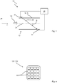
- Fig. 1
- eine schematische Darstellung eines Durchflussmessgeräts nach dem Stand der Technik;
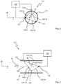
- Fig. 2
- eine schematische Darstellung eines erfindungsgemäßen Durchflussmessgeräts in Rohrlängsrichtung gesehen;
- Fig. 3
- eine schematische Darstellung des erfindungsgemäßen Durchflussmessgeräts aus
Fig. 2 quer zur Rohrlängsrichtung gesehen; - Fig. 4
- eine schematische Ansicht eines phased-array Ultraschallwandlers;
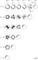
- Fig. 5
- Darstellungen von Messpfaden in Rohrlängsrichtung gesehen;
- Fig. 6
- eine Ansicht wie
Fig. 2 . - In
Fig. 1 ist ein Durchflussmessgerät 10 nach dem Stand der Technik dargestellt zur allgemeinen Erläuterung der Funktion eines gattungsgemäßen Durchflussmessgeräts. Das Durchflussmessgerät 10 umfasst einen Messaufnehmer 12, der eine Rohrleitung 14 für das Fluid mit einer Rohrwand 16 aufweist. Das durch die Rohrleitung 14 strömende Fluid, ein Gas oder eine Flüssigkeit, ist inFig. 1 mit einem breiten Pfeil 18 dargestellt und strömt in z-Richtung entlang einer Längsrichtung 26 der Rohrleitung 14. - Weiter weist das Durchflussmessgerät 10 zwei Ultraschallwandler 20 und 22 auf, die zwischen sich in der Rohrleitung 14 einen Messpfad 24 definieren. Die Ultraschallwandler 20 und 22 sind in Strömungsrichtung z versetzt angeordnet, also sie sind in Längsrichtung 26 der Rohrleitung 14 beabstandet. Dadurch liegt der Messpfad 24 nicht orthogonal zur Strömungsrichtung z, sondern in einem Winkel α. Jede der Ultraschallwandlereinheiten 20 und 22 kann als Sender oder Empfänger arbeiten und wird von einer Steuer- und Auswerteeinheit 28 gesteuert.
- Aus dem Winkel α und dem Rohrdurchmesser D ergibt sich die Länge L des Messpfades 24 im fluiden Medium. Ultraschallsignale, die als Ultraschallwellenpakete auf dem Messpfad 24 in entgegengesetzte Richtungen ausgesandt und empfangen werden, haben also einmal eine Komponente in Richtung der Strömungsrichtung z und ein anders Mal entgegen der Strömungsrichtung z und werden somit mit der Strömung 18 beschleunigt bzw. entgegen der Strömung 18 abgebremst. Die Strömungsgeschwindigkeit v des Fluids 18 berechnet sich in diesem Laufzeitverfahren nach

- Nach diesem Prinzip arbeitet auch das erfindungsgemäße Durchflussmessgerät 110, das in
Fig. 2 und 3 sehr schematisch dargestellt ist. Es weist ebenso einen Messaufnehmer 112 mit Rohrleitung 114 sowie zwei Ultraschallwandlereinheiten 120 und 122 in einer Rohrwand 116 und eine Steuer- und Auswerteeinheit 128 auf. - Die Ultraschallwandlereinheiten 120 bzw. 122 sind allerdings keine "einfachen" Ultraschallwandler, sondern sind als phased-array Ultraschallwandlereinheiten ausgebildet. Sie weisen, wie in der schematischen Draufsicht der
Fig. 4 auf eine schallabstrahlende Seite der Ultraschallwandlereinheit 120 bzw. 122 schematisch dargestellt ist, jeweils ein zweidimensionales Array von einzeln ansteuerbaren Ultraschallwandlern 123 auf. Die einzelnen Ultraschallwandler 123 werden zum Ausstrahlen eines Ultraschallpakets von der Steuer- und Auswerteeinheit 128 so angesteuert, dass sie untereinander jeweils einen Phasenversatz aufweisen, wobei der Phasenversatz so gewählt ist, dass die Überlagerung der daraus resultierenden Ultraschallwellen zu einem Ultraschallwellenpaket führt, das sich entlang eines bestimmten Messpfades 124 bewegt. Die Lage des Messpfades 124 wird also durch den Phasenversatz bestimmt und sollte so ausgerichtet sein, dass das Ultraschallwellenpaket die andere Ultraschallwandlereinheit erreicht. - Die Erfindung steckt im Wesentlichen in der Positionierung der beiden Ultraschallwandlereinheiten 120 und 122 und der Wahl der möglichen Messpfade 124.
- In den
Fig. 2 und 3 ist eine beispielhafte Anordnung der Ultraschallwandlereinheiten 120 und 122 gezeigt. Um die relative Anordnung der Ultraschallwandler 120 und 122 zu beschreiben wird für die Zwecke dieser Beschreibung ein Einbauwinkel β definiert. Unter dem Einbauwinkel β ist der Winkel zwischen den beiden Ultraschallwandlereinheiten 120 und 122 zu verstehen, der sich ergibt, wenn man in Längsrichtung entlang der Mittelachse 126 der Rohrleitung 114 schaut und die relative Lage der Ultraschallwandlereinheiten 120 und 122 auf dem Rohrumfang zueinander anschaut (Fig. 2 ). Oder anders ausgedrückt, ist das der Winkel β, den in der Längsrichtungssicht die beiden Verbindungen zwischen Ultraschallwandler 120 bzw. 122 und Mittelachse 126 einschließen. Ein Einbauwinkel von 180° würde einer diametralen Montage entsprechen. InFig. 2 ist ein Einbauwinkel β von 90° dargestellt. - Gemäß der Erfindung liegen die Ultraschallwandlereinheiten 120 und 122 in einem Einbauwinkel, der zwischen 20° und 140° liegt und insbesondere zwischen 30° und 50°.
- Für die Beispiele aus dieser Beschreibung (
Fig. 2, 3 und5 ) wurde ein Einbauwinkel β von 90° gewählt, da sich ein solcher zeichnerisch und zur beschreibenden Erläuterung am Besten eignet. - In den
Fig. 2 und 3 sind in dieser Ultraschallanordnung zwei Messpfade 124-0 und 124-1 beispielhaft eingezeichnet. Auf dem ersten Messpfad 124-0 gelangen die Ultraschallsignale auf direktem Weg von der einen Ultraschallwandlereinheit 120 bzw. 122 zur anderen Ultraschallwandlereinheit 122 bzw. 120. Dieser direkte Messpfad 124-0 beinhaltet also keine Reflexion an der Rohrwand 116. Das soll auch durch den Zusatz "-0" zum Bezugszeichen ausgedrückt sein. Auf dem anderen eingezeichneten Messpfad 124-1 erfahren die Ultraschallsignale eine Reflexion an einer Stelle 130 an der Rohrwand 116 (auch ausgedrückt durch den Zusatz "-1"). Durch die Reflexion ist der Messpfad 124-1 in zwei Pfadabschnitte 124-1a und 124-1b aufgeteilt. Die beiden Pfadabschnitte 124-1a und 124-1b sind gleich lang, auch wenn dies in der Zeichenebene der eigentlich dreidimensionalen Anordnung derFig. 3 anders aussieht. Ein Pfadabschnitt, hier 124-1a bzw. 124-1b ist also immer der Teil eines Messpfades, hier 124, auf dem sich der Ultraschall ungehindert geradlinig ausbreiten kann. - Mit der erfindungsgemäßen Anordnung, bestehend aus den zwei Ultraschallwandlereinheiten 120 und 124 in einem Einbauwinkel β sind selbstverständlich auch andere als die in
Fig. 2 und 3 dargestellten Messpfade 124-0 und 124-1 möglich. - Mögliche Messpfade 124 sind in
Fig. 5 vereinfacht dargestellt. Das sind Messpfade mit 0 bis 5 Reflexionen. Die Messpfade 124-0 mit keiner Reflexion und 124-1 mit einer Reflexion und Pfadabschnitten 124-1a und 124-1b wurden oben unter Bezugnahme auf dieFig. 2 und 3 erläutert. Wie sich unschwer erkennen lässt, sind bei N Reflexionen immer N+1 Alternativen für den Messpfad möglich. Diese Pfadalternativen sind mit Großbuchstaben A bis F gekennzeichnet. So gibt es zum Beispiel für den Messpfad 124-1 mit nur einer Reflexion noch eine Alternative B, bei der die Pfadabschnitte relativ nahe an der Wand liegen. - Die Erfinder haben herausgefunden, dass in vorteilhafter Ausbildung der Erfindung nicht mehr als fünf Reflexionen pro Messpfad vorliegen sollten, also das Design der Messpfade 124 auf die in
Fig. 5 Dargestellten begrenzt sein sollte. Messpfade mit mehr als fünf Reflexionen liefern keinen Mehrwert, denn viele der möglichen Messpfade mit mehr als fünf Reflexionen sind nicht sinnvoll verwendbar, da deren Pfadabschnitte beispielsweise entlang des Randes des Rohres gelegen sind (wie inFig. 5 bereits für Messpfad 124-5 in der Alternative F erkennbar) oder zu sehr in der Mitte liegen und daher fast schon diametral verlaufen (wie Messpfad 124-5 in der Alternative C in der Tendenz zeigt). Wenn die Messpfade in den aufgezeigten Grenzen bleiben, liegen die Pfadabschnitte dieser Messpfade 124 in sinnvollen und unterschiedlichen Bereichen des Querschnitts, so dass der Durchfluss über den Querschnitt der Rohrleitung 114 besser erfasst wird. - Weiter haben die Erfinder herausgefunden, dass es besonders vorteilhaft ist, wenn für die Pfadabschnitte gilt, dass r/R zwischen 0,3 und 0,65 liegt, wobei R der Rohrdurchmesser ist und r der kürzeste Abstand eines Pfadabschnittes zum Mittelpunkt ist (in
Fig. 6 anhand des Pfadabschnitts 124-1a gezeigt). Dann liegen die Messpfade 124 mit ihren Pfadabschnitten besonders günstig, um die Strömung 18 sinnvoll abzutasten. Sie liegen außermittig aber auch nicht zu nahe am Rand. Die Pfade liegen dann auch näherungsweise auf dem Gaußschen Knoten. Das ist vorteilhaft, denn im Gaußschen Knoten ändert sich das Strömungsprofil nicht mit der Geschwindigkeit des Fluids. Insgesamt ergibt das eine höhere Messgenauigkeit. Messpfade, für die das besonders gut zutrifft, wären zum Beispiel folgende Messpfade: - 124-1 Alternative A
- 124-2 Alternativen A und B
- 124-3 Alternativen B und C
- 124-4 Alternativen B und C
- 124-5 Alternativen B und D.
Claims (4)
- Durchflussmessgerät zur Messung des Durchflusses eines Fluids (18) mit- einem Messaufnehmer (112), der eine Rohrleitung (114) für das Fluid (18) aufweist,- zwei, in Längsrichtung (126) der Rohrleitung (114) beabstandete phased-array Ultraschallwandlereinheiten (120, 122), die Ultraschallsignale in verschiedene Winkel abstrahlen und empfangen können,- einer Steuer- und Auswerteeinheit (128) zur Ansteuerung der Ultraschallwandlereinheiten (120, 122) und Auswertung der empfangenen Ultraschallsignale und Bestimmen des Durchflusses unter Verwendung der Laufzeit der Ultraschallsignale auf den Messpfaden (124),- wobei die Ultraschallwandlereinheiten (120, 122) zwischen sich je nach Winkel der abgestrahlten Ultraschallsignale wenigstens zwei Messpfade (124-0, 124-1, 124-2, 124-3, 124-4, 124-5) definieren, auf denen die Ultraschallsignale von einer zur anderen Ultraschallwandlereinheit gelangen,- wobei wenigstens einer der Messpfade (124-1, 124-2, 124-3, 124-4, 124-5) wenigstens eine Reflexion (130) an einer Rohrwand (116) der Rohrleitung (114) aufweist und durch die Reflexion bzw. Reflexionen Pfadabschnitte (124-1a, 124-1b) definiert sind,- wobei die Ultraschallwandlereinheiten (120, 122) in einem Einbauwinkel (β) liegen, der zwischen 20° und 140° liegt.
- Durchflussmessgerät nach Anspruch 1, dadurch gekennzeichnet, dass der Einbauwinkel zwischen 30° und 50° liegt.
- Durchflussmessgerät nach einem der vorhergehenden Ansprüche, dadurch gekennzeichnet, dass für die Pfadabschnitte gilt, dass r/R zwischen 0,3 und 0,65 liegt, wobei R der Rohrdurchmesser ist und r der kürzeste Abstand eines Pfadabschnittes zum Mittelpunkt ist.
- Durchflussmessgerät nach einem der vorhergehenden Ansprüche, dadurch gekennzeichnet, dass nicht mehr als fünf Reflexionen pro Messpfad vorliegen.
Priority Applications (3)
| Application Number | Priority Date | Filing Date | Title |
|---|---|---|---|
| EP20168003.0A EP3889552B1 (de) | 2020-04-03 | 2020-04-03 | Durchflussmessgerät |
| RU2021106649A RU2760627C1 (ru) | 2020-04-03 | 2021-03-15 | Прибор измерения расхода |
| US17/221,508 US11761805B2 (en) | 2020-04-03 | 2021-04-02 | Flowmeter |
Applications Claiming Priority (1)
| Application Number | Priority Date | Filing Date | Title |
|---|---|---|---|
| EP20168003.0A EP3889552B1 (de) | 2020-04-03 | 2020-04-03 | Durchflussmessgerät |
Publications (2)
| Publication Number | Publication Date |
|---|---|
| EP3889552A1 true EP3889552A1 (de) | 2021-10-06 |
| EP3889552B1 EP3889552B1 (de) | 2023-08-02 |
Family
ID=70189725
Family Applications (1)
| Application Number | Title | Priority Date | Filing Date |
|---|---|---|---|
| EP20168003.0A Active EP3889552B1 (de) | 2020-04-03 | 2020-04-03 | Durchflussmessgerät |
Country Status (3)
| Country | Link |
|---|---|
| US (1) | US11761805B2 (de) |
| EP (1) | EP3889552B1 (de) |
| RU (1) | RU2760627C1 (de) |
Citations (4)
| Publication number | Priority date | Publication date | Assignee | Title |
|---|---|---|---|---|
| DE29719730U1 (de) * | 1997-11-06 | 1998-12-03 | Siemens AG, 80333 München | Durchflußmeßgerät |
| US20140366642A1 (en) * | 2013-06-18 | 2014-12-18 | Yokogawa Electric Corporation | Ultrasonic flowmeter |
| EP3521773A1 (de) * | 2018-02-06 | 2019-08-07 | SICK Engineering GmbH | Ultraschall-durchflussmessvorrichtung und verfahren zum bestimmen einer strömungsgeschwindigkeit |
| US20200072649A1 (en) * | 2017-03-14 | 2020-03-05 | Endress+Hauser Flowtec Ag | Ultrasonic flowmeter |
Family Cites Families (8)
| Publication number | Priority date | Publication date | Assignee | Title |
|---|---|---|---|---|
| US5228347A (en) * | 1991-10-18 | 1993-07-20 | Ore International, Inc. | Method and apparatus for measuring flow by using phase advance |
| DE19632165A1 (de) * | 1996-08-09 | 1998-02-12 | Elster Produktion Gmbh | Verfahren und Vorrichtung zur Ultraschall-Durchflußmessung |
| DE10235033B4 (de) * | 2002-07-31 | 2006-07-27 | Hydrometer Gmbh | Durchflußmesser |
| DE10248593A1 (de) * | 2002-10-17 | 2004-04-29 | Endress + Hauser Flowtec Ag, Reinach | Durchflußmeßgerät |
| EP2282178B1 (de) * | 2009-07-23 | 2016-10-19 | Elster NV/SA | Ultraschall-Durchflussmesser zum Messen einer Flusseigenschaft einer Flüssigkeit in einem Kanal |
| EP2278280B1 (de) * | 2009-07-23 | 2019-09-04 | Elster NV/SA | Vorrichtung und Verfahren zur Bestimmung einer Flusseigenschaft einer Flüssigkeit in einem Kanal |
| GB2521661A (en) * | 2013-12-27 | 2015-07-01 | Xsens As | Apparatus and method for measuring flow |
| DE102017110308A1 (de) * | 2017-05-12 | 2018-11-15 | Krohne Ag | Ultraschalldurchflussmessgerät |
-
2020
- 2020-04-03 EP EP20168003.0A patent/EP3889552B1/de active Active
-
2021
- 2021-03-15 RU RU2021106649A patent/RU2760627C1/ru active
- 2021-04-02 US US17/221,508 patent/US11761805B2/en active Active
Patent Citations (4)
| Publication number | Priority date | Publication date | Assignee | Title |
|---|---|---|---|---|
| DE29719730U1 (de) * | 1997-11-06 | 1998-12-03 | Siemens AG, 80333 München | Durchflußmeßgerät |
| US20140366642A1 (en) * | 2013-06-18 | 2014-12-18 | Yokogawa Electric Corporation | Ultrasonic flowmeter |
| US20200072649A1 (en) * | 2017-03-14 | 2020-03-05 | Endress+Hauser Flowtec Ag | Ultrasonic flowmeter |
| EP3521773A1 (de) * | 2018-02-06 | 2019-08-07 | SICK Engineering GmbH | Ultraschall-durchflussmessvorrichtung und verfahren zum bestimmen einer strömungsgeschwindigkeit |
Also Published As
| Publication number | Publication date |
|---|---|
| US20210310839A1 (en) | 2021-10-07 |
| EP3889552B1 (de) | 2023-08-02 |
| US11761805B2 (en) | 2023-09-19 |
| RU2760627C1 (ru) | 2021-11-29 |
Similar Documents
| Publication | Publication Date | Title |
|---|---|---|
| EP2732248B1 (de) | Ultraschall-durchflussmessgerät | |
| DE102019110514B4 (de) | Fluidmesseinrichtung | |
| DE10312034B3 (de) | Ultraschalldurchflußmeßverfahren | |
| EP1936333B1 (de) | Ultraschalldurchflussmessgerät | |
| DE102013114475B4 (de) | Ultraschallmessvorrichtung und Verfahren zum Bestimmen der Strömungsgeschwindigkeit | |
| EP3521773B1 (de) | Ultraschall-durchflussmessvorrichtung und verfahren zum bestimmen einer strömungsgeschwindigkeit | |
| EP3404372B1 (de) | Ultraschalldurchflussmessgerät | |
| DE2648718B1 (de) | Mit Ultraschall arbeitendes Geraet zum Ermitteln physikalischer Groessen eines Mediums | |
| EP3388794B2 (de) | Messvorrichtung zum messen einer durchflussgeschwindigkeit eines fluids | |
| EP3855134B1 (de) | Vorrichtung zur messung der flussgeschwindigkeit eines fluids | |
| WO2018015218A1 (de) | Verfahren und anordnung zur ultraschall-clamp-on-durchflussmessung und körper zur realisierung der messung | |
| EP4182703B1 (de) | Durchflussmessgerät und verfahren zur messung des durchflusses eines fluids | |
| EP3521774A1 (de) | Ultraschall-durchflussmessvorrichtung und verfahren zum bestimmen der strömungsgeschwindigkeit | |
| EP0831303B1 (de) | Wirbel-Strömungsaufnehmer mit einem Turbulenzgitter | |
| EP3894799B1 (de) | Ultraschallwandleranordnung einer clamp-on-ultraschall-durchflussmessstelle, und eine clamp-on-ultraschall-durchflussmessstelle sowie verfahren zur inbetriebnahme der clamp-on-ultraschall-durchflussmessstelle | |
| EP2656018A1 (de) | Ultraschall-durchflussmessgerät | |
| DE202020104105U1 (de) | Durchflussmessgerät zur Messung des Durchflusses eines Fluids | |
| DE19648784C2 (de) | Ultraschall-Durchflußmesser | |
| EP3748308A1 (de) | Ultraschalldurchflussmessgerät, verwendung eines ultraschalldurchflussmessgerätes in einem absperrorgan und absperrorgan | |
| DE69413543T2 (de) | Verbesserungen bezüglich der überwachung von flüssigkeitsströmungen | |
| EP3405781B1 (de) | Vorrichtung zur bestimmung von eigenschaften eines mediums mit dämpfungselement und/oder offenem leitelement | |
| EP3889552B1 (de) | Durchflussmessgerät | |
| EP3514505A1 (de) | Strömungsmesser | |
| EP3748309B1 (de) | Ultraschalldurchflussmessgerät, verwendung eines ultraschalldurchflussmessgerätes in einem absperrorgan und absperrorgan | |
| DE202020101838U1 (de) | Durchflussmessgerät |
Legal Events
| Date | Code | Title | Description |
|---|---|---|---|
| PUAI | Public reference made under article 153(3) epc to a published international application that has entered the european phase |
Free format text: ORIGINAL CODE: 0009012 |
|
| STAA | Information on the status of an ep patent application or granted ep patent |
Free format text: STATUS: THE APPLICATION HAS BEEN PUBLISHED |
|
| AK | Designated contracting states |
Kind code of ref document: A1 Designated state(s): AL AT BE BG CH CY CZ DE DK EE ES FI FR GB GR HR HU IE IS IT LI LT LU LV MC MK MT NL NO PL PT RO RS SE SI SK SM TR |
|
| STAA | Information on the status of an ep patent application or granted ep patent |
Free format text: STATUS: REQUEST FOR EXAMINATION WAS MADE |
|
| 17P | Request for examination filed |
Effective date: 20220406 |
|
| RBV | Designated contracting states (corrected) |
Designated state(s): AL AT BE BG CH CY CZ DE DK EE ES FI FR GB GR HR HU IE IS IT LI LT LU LV MC MK MT NL NO PL PT RO RS SE SI SK SM TR |
|
| REG | Reference to a national code |
Ref country code: DE Free format text: PREVIOUS MAIN CLASS: G01F0001660000 Ref country code: DE Ref legal event code: R079 Ref document number: 502020004436 Country of ref document: DE Free format text: PREVIOUS MAIN CLASS: G01F0001660000 Ipc: G01F0001667000 |
|
| RIC1 | Information provided on ipc code assigned before grant |
Ipc: G01F 1/667 20220101AFI20230403BHEP |
|
| GRAP | Despatch of communication of intention to grant a patent |
Free format text: ORIGINAL CODE: EPIDOSNIGR1 |
|
| STAA | Information on the status of an ep patent application or granted ep patent |
Free format text: STATUS: GRANT OF PATENT IS INTENDED |
|
| INTG | Intention to grant announced |
Effective date: 20230517 |
|
| GRAS | Grant fee paid |
Free format text: ORIGINAL CODE: EPIDOSNIGR3 |
|
| GRAA | (expected) grant |
Free format text: ORIGINAL CODE: 0009210 |
|
| STAA | Information on the status of an ep patent application or granted ep patent |
Free format text: STATUS: THE PATENT HAS BEEN GRANTED |
|
| AK | Designated contracting states |
Kind code of ref document: B1 Designated state(s): AL AT BE BG CH CY CZ DE DK EE ES FI FR GB GR HR HU IE IS IT LI LT LU LV MC MK MT NL NO PL PT RO RS SE SI SK SM TR |
|
| REG | Reference to a national code |
Ref country code: GB Ref legal event code: FG4D Free format text: NOT ENGLISH |
|
| REG | Reference to a national code |
Ref country code: CH Ref legal event code: EP |
|
| REG | Reference to a national code |
Ref country code: DE Ref legal event code: R096 Ref document number: 502020004436 Country of ref document: DE |
|
| REG | Reference to a national code |
Ref country code: IE Ref legal event code: FG4D Free format text: LANGUAGE OF EP DOCUMENT: GERMAN |
|
| REG | Reference to a national code |
Ref country code: LT Ref legal event code: MG9D |
|
| REG | Reference to a national code |
Ref country code: NL Ref legal event code: MP Effective date: 20230802 |
|
| PG25 | Lapsed in a contracting state [announced via postgrant information from national office to epo] |
Ref country code: GR Free format text: LAPSE BECAUSE OF FAILURE TO SUBMIT A TRANSLATION OF THE DESCRIPTION OR TO PAY THE FEE WITHIN THE PRESCRIBED TIME-LIMIT Effective date: 20231103 |
|
| PG25 | Lapsed in a contracting state [announced via postgrant information from national office to epo] |
Ref country code: IS Free format text: LAPSE BECAUSE OF FAILURE TO SUBMIT A TRANSLATION OF THE DESCRIPTION OR TO PAY THE FEE WITHIN THE PRESCRIBED TIME-LIMIT Effective date: 20231202 |
|
| PG25 | Lapsed in a contracting state [announced via postgrant information from national office to epo] |
Ref country code: SE Free format text: LAPSE BECAUSE OF FAILURE TO SUBMIT A TRANSLATION OF THE DESCRIPTION OR TO PAY THE FEE WITHIN THE PRESCRIBED TIME-LIMIT Effective date: 20230802 Ref country code: RS Free format text: LAPSE BECAUSE OF FAILURE TO SUBMIT A TRANSLATION OF THE DESCRIPTION OR TO PAY THE FEE WITHIN THE PRESCRIBED TIME-LIMIT Effective date: 20230802 Ref country code: PT Free format text: LAPSE BECAUSE OF FAILURE TO SUBMIT A TRANSLATION OF THE DESCRIPTION OR TO PAY THE FEE WITHIN THE PRESCRIBED TIME-LIMIT Effective date: 20231204 Ref country code: NO Free format text: LAPSE BECAUSE OF FAILURE TO SUBMIT A TRANSLATION OF THE DESCRIPTION OR TO PAY THE FEE WITHIN THE PRESCRIBED TIME-LIMIT Effective date: 20231102 Ref country code: NL Free format text: LAPSE BECAUSE OF FAILURE TO SUBMIT A TRANSLATION OF THE DESCRIPTION OR TO PAY THE FEE WITHIN THE PRESCRIBED TIME-LIMIT Effective date: 20230802 Ref country code: LV Free format text: LAPSE BECAUSE OF FAILURE TO SUBMIT A TRANSLATION OF THE DESCRIPTION OR TO PAY THE FEE WITHIN THE PRESCRIBED TIME-LIMIT Effective date: 20230802 Ref country code: LT Free format text: LAPSE BECAUSE OF FAILURE TO SUBMIT A TRANSLATION OF THE DESCRIPTION OR TO PAY THE FEE WITHIN THE PRESCRIBED TIME-LIMIT Effective date: 20230802 Ref country code: IS Free format text: LAPSE BECAUSE OF FAILURE TO SUBMIT A TRANSLATION OF THE DESCRIPTION OR TO PAY THE FEE WITHIN THE PRESCRIBED TIME-LIMIT Effective date: 20231202 Ref country code: HR Free format text: LAPSE BECAUSE OF FAILURE TO SUBMIT A TRANSLATION OF THE DESCRIPTION OR TO PAY THE FEE WITHIN THE PRESCRIBED TIME-LIMIT Effective date: 20230802 Ref country code: GR Free format text: LAPSE BECAUSE OF FAILURE TO SUBMIT A TRANSLATION OF THE DESCRIPTION OR TO PAY THE FEE WITHIN THE PRESCRIBED TIME-LIMIT Effective date: 20231103 Ref country code: FI Free format text: LAPSE BECAUSE OF FAILURE TO SUBMIT A TRANSLATION OF THE DESCRIPTION OR TO PAY THE FEE WITHIN THE PRESCRIBED TIME-LIMIT Effective date: 20230802 |
|
| PG25 | Lapsed in a contracting state [announced via postgrant information from national office to epo] |
Ref country code: PL Free format text: LAPSE BECAUSE OF FAILURE TO SUBMIT A TRANSLATION OF THE DESCRIPTION OR TO PAY THE FEE WITHIN THE PRESCRIBED TIME-LIMIT Effective date: 20230802 |
|
| PG25 | Lapsed in a contracting state [announced via postgrant information from national office to epo] |
Ref country code: ES Free format text: LAPSE BECAUSE OF FAILURE TO SUBMIT A TRANSLATION OF THE DESCRIPTION OR TO PAY THE FEE WITHIN THE PRESCRIBED TIME-LIMIT Effective date: 20230802 |
|
| PG25 | Lapsed in a contracting state [announced via postgrant information from national office to epo] |
Ref country code: SM Free format text: LAPSE BECAUSE OF FAILURE TO SUBMIT A TRANSLATION OF THE DESCRIPTION OR TO PAY THE FEE WITHIN THE PRESCRIBED TIME-LIMIT Effective date: 20230802 Ref country code: RO Free format text: LAPSE BECAUSE OF FAILURE TO SUBMIT A TRANSLATION OF THE DESCRIPTION OR TO PAY THE FEE WITHIN THE PRESCRIBED TIME-LIMIT Effective date: 20230802 Ref country code: ES Free format text: LAPSE BECAUSE OF FAILURE TO SUBMIT A TRANSLATION OF THE DESCRIPTION OR TO PAY THE FEE WITHIN THE PRESCRIBED TIME-LIMIT Effective date: 20230802 Ref country code: EE Free format text: LAPSE BECAUSE OF FAILURE TO SUBMIT A TRANSLATION OF THE DESCRIPTION OR TO PAY THE FEE WITHIN THE PRESCRIBED TIME-LIMIT Effective date: 20230802 Ref country code: DK Free format text: LAPSE BECAUSE OF FAILURE TO SUBMIT A TRANSLATION OF THE DESCRIPTION OR TO PAY THE FEE WITHIN THE PRESCRIBED TIME-LIMIT Effective date: 20230802 Ref country code: CZ Free format text: LAPSE BECAUSE OF FAILURE TO SUBMIT A TRANSLATION OF THE DESCRIPTION OR TO PAY THE FEE WITHIN THE PRESCRIBED TIME-LIMIT Effective date: 20230802 Ref country code: SK Free format text: LAPSE BECAUSE OF FAILURE TO SUBMIT A TRANSLATION OF THE DESCRIPTION OR TO PAY THE FEE WITHIN THE PRESCRIBED TIME-LIMIT Effective date: 20230802 |
|
| REG | Reference to a national code |
Ref country code: DE Ref legal event code: R097 Ref document number: 502020004436 Country of ref document: DE |
|
| PLBE | No opposition filed within time limit |
Free format text: ORIGINAL CODE: 0009261 |
|
| STAA | Information on the status of an ep patent application or granted ep patent |
Free format text: STATUS: NO OPPOSITION FILED WITHIN TIME LIMIT |
|
| 26N | No opposition filed |
Effective date: 20240503 |
|
| PG25 | Lapsed in a contracting state [announced via postgrant information from national office to epo] |
Ref country code: SI Free format text: LAPSE BECAUSE OF FAILURE TO SUBMIT A TRANSLATION OF THE DESCRIPTION OR TO PAY THE FEE WITHIN THE PRESCRIBED TIME-LIMIT Effective date: 20230802 |
|
| PG25 | Lapsed in a contracting state [announced via postgrant information from national office to epo] |
Ref country code: BG Free format text: LAPSE BECAUSE OF FAILURE TO SUBMIT A TRANSLATION OF THE DESCRIPTION OR TO PAY THE FEE WITHIN THE PRESCRIBED TIME-LIMIT Effective date: 20230802 |
|
| PG25 | Lapsed in a contracting state [announced via postgrant information from national office to epo] |
Ref country code: MC Free format text: LAPSE BECAUSE OF FAILURE TO SUBMIT A TRANSLATION OF THE DESCRIPTION OR TO PAY THE FEE WITHIN THE PRESCRIBED TIME-LIMIT Effective date: 20230802 |
|
| PG25 | Lapsed in a contracting state [announced via postgrant information from national office to epo] |
Ref country code: MC Free format text: LAPSE BECAUSE OF FAILURE TO SUBMIT A TRANSLATION OF THE DESCRIPTION OR TO PAY THE FEE WITHIN THE PRESCRIBED TIME-LIMIT Effective date: 20230802 Ref country code: BG Free format text: LAPSE BECAUSE OF FAILURE TO SUBMIT A TRANSLATION OF THE DESCRIPTION OR TO PAY THE FEE WITHIN THE PRESCRIBED TIME-LIMIT Effective date: 20230802 |
|
| REG | Reference to a national code |
Ref country code: CH Ref legal event code: PL |
|
| PG25 | Lapsed in a contracting state [announced via postgrant information from national office to epo] |
Ref country code: LU Free format text: LAPSE BECAUSE OF NON-PAYMENT OF DUE FEES Effective date: 20240403 |
|
| REG | Reference to a national code |
Ref country code: BE Ref legal event code: MM Effective date: 20240430 |
|
| PG25 | Lapsed in a contracting state [announced via postgrant information from national office to epo] |
Ref country code: LU Free format text: LAPSE BECAUSE OF NON-PAYMENT OF DUE FEES Effective date: 20240403 |
|
| PG25 | Lapsed in a contracting state [announced via postgrant information from national office to epo] |
Ref country code: BE Free format text: LAPSE BECAUSE OF NON-PAYMENT OF DUE FEES Effective date: 20240430 |
|
| PG25 | Lapsed in a contracting state [announced via postgrant information from national office to epo] |
Ref country code: BE Free format text: LAPSE BECAUSE OF NON-PAYMENT OF DUE FEES Effective date: 20240430 Ref country code: CH Free format text: LAPSE BECAUSE OF NON-PAYMENT OF DUE FEES Effective date: 20240430 |
|
| PG25 | Lapsed in a contracting state [announced via postgrant information from national office to epo] |
Ref country code: IE Free format text: LAPSE BECAUSE OF NON-PAYMENT OF DUE FEES Effective date: 20240403 |
|
| PGFP | Annual fee paid to national office [announced via postgrant information from national office to epo] |
Ref country code: DE Payment date: 20250417 Year of fee payment: 6 |
|
| PGFP | Annual fee paid to national office [announced via postgrant information from national office to epo] |
Ref country code: GB Payment date: 20250423 Year of fee payment: 6 |
|
| PGFP | Annual fee paid to national office [announced via postgrant information from national office to epo] |
Ref country code: IT Payment date: 20250430 Year of fee payment: 6 |
|
| PGFP | Annual fee paid to national office [announced via postgrant information from national office to epo] |
Ref country code: FR Payment date: 20250422 Year of fee payment: 6 |
|
| PGFP | Annual fee paid to national office [announced via postgrant information from national office to epo] |
Ref country code: AT Payment date: 20250721 Year of fee payment: 5 |
|
| PG25 | Lapsed in a contracting state [announced via postgrant information from national office to epo] |
Ref country code: CY Free format text: LAPSE BECAUSE OF FAILURE TO SUBMIT A TRANSLATION OF THE DESCRIPTION OR TO PAY THE FEE WITHIN THE PRESCRIBED TIME-LIMIT; INVALID AB INITIO Effective date: 20200403 |
|
| PG25 | Lapsed in a contracting state [announced via postgrant information from national office to epo] |
Ref country code: HU Free format text: LAPSE BECAUSE OF FAILURE TO SUBMIT A TRANSLATION OF THE DESCRIPTION OR TO PAY THE FEE WITHIN THE PRESCRIBED TIME-LIMIT; INVALID AB INITIO Effective date: 20200403 |
|
| PG25 | Lapsed in a contracting state [announced via postgrant information from national office to epo] |
Ref country code: TR Free format text: LAPSE BECAUSE OF FAILURE TO SUBMIT A TRANSLATION OF THE DESCRIPTION OR TO PAY THE FEE WITHIN THE PRESCRIBED TIME-LIMIT Effective date: 20230802 |
|
| REG | Reference to a national code |
Ref country code: DE Ref legal event code: R081 Ref document number: 502020004436 Country of ref document: DE Owner name: ENDRESS+HAUSER SICK GMBH+CO. KG, DE Free format text: FORMER OWNER: SICK ENGINEERING GMBH, 01458 OTTENDORF-OKRILLA, DE Ref country code: DE Ref legal event code: R082 Ref document number: 502020004436 Country of ref document: DE |