EP3889640A2 - Génération de chirps multiples dans un système radar - Google Patents
Génération de chirps multiples dans un système radar Download PDFInfo
- Publication number
- EP3889640A2 EP3889640A2 EP21157976.8A EP21157976A EP3889640A2 EP 3889640 A2 EP3889640 A2 EP 3889640A2 EP 21157976 A EP21157976 A EP 21157976A EP 3889640 A2 EP3889640 A2 EP 3889640A2
- Authority
- EP
- European Patent Office
- Prior art keywords
- chirp
- profile
- radar device
- parameter values
- chirps
- Prior art date
- Legal status (The legal status is an assumption and is not a legal conclusion. Google has not performed a legal analysis and makes no representation as to the accuracy of the status listed.)
- Pending
Links
Images


Classifications
-
- G—PHYSICS
- G01—MEASURING; TESTING
- G01S—RADIO DIRECTION-FINDING; RADIO NAVIGATION; DETERMINING DISTANCE OR VELOCITY BY USE OF RADIO WAVES; LOCATING OR PRESENCE-DETECTING BY USE OF THE REFLECTION OR RERADIATION OF RADIO WAVES; ANALOGOUS ARRANGEMENTS USING OTHER WAVES
- G01S7/00—Details of systems according to groups G01S13/00, G01S15/00, G01S17/00
- G01S7/02—Details of systems according to groups G01S13/00, G01S15/00, G01S17/00 of systems according to group G01S13/00
- G01S7/35—Details of non-pulse systems
-
- G—PHYSICS
- G01—MEASURING; TESTING
- G01S—RADIO DIRECTION-FINDING; RADIO NAVIGATION; DETERMINING DISTANCE OR VELOCITY BY USE OF RADIO WAVES; LOCATING OR PRESENCE-DETECTING BY USE OF THE REFLECTION OR RERADIATION OF RADIO WAVES; ANALOGOUS ARRANGEMENTS USING OTHER WAVES
- G01S13/00—Systems using the reflection or reradiation of radio waves, e.g. radar systems; Analogous systems using reflection or reradiation of waves whose nature or wavelength is irrelevant or unspecified
- G01S13/02—Systems using reflection of radio waves, e.g. primary radar systems; Analogous systems
- G01S13/06—Systems determining position data of a target
- G01S13/08—Systems for measuring distance only
- G01S13/32—Systems for measuring distance only using transmission of continuous waves, whether amplitude-, frequency-, or phase-modulated, or unmodulated
- G01S13/34—Systems for measuring distance only using transmission of continuous waves, whether amplitude-, frequency-, or phase-modulated, or unmodulated using transmission of continuous, frequency-modulated waves while heterodyning the received signal, or a signal derived therefrom, with a locally-generated signal related to the contemporaneously transmitted signal
-
- G—PHYSICS
- G01—MEASURING; TESTING
- G01S—RADIO DIRECTION-FINDING; RADIO NAVIGATION; DETERMINING DISTANCE OR VELOCITY BY USE OF RADIO WAVES; LOCATING OR PRESENCE-DETECTING BY USE OF THE REFLECTION OR RERADIATION OF RADIO WAVES; ANALOGOUS ARRANGEMENTS USING OTHER WAVES
- G01S13/00—Systems using the reflection or reradiation of radio waves, e.g. radar systems; Analogous systems using reflection or reradiation of waves whose nature or wavelength is irrelevant or unspecified
- G01S13/02—Systems using reflection of radio waves, e.g. primary radar systems; Analogous systems
- G01S13/06—Systems determining position data of a target
- G01S13/08—Systems for measuring distance only
- G01S13/32—Systems for measuring distance only using transmission of continuous waves, whether amplitude-, frequency-, or phase-modulated, or unmodulated
- G01S13/34—Systems for measuring distance only using transmission of continuous waves, whether amplitude-, frequency-, or phase-modulated, or unmodulated using transmission of continuous, frequency-modulated waves while heterodyning the received signal, or a signal derived therefrom, with a locally-generated signal related to the contemporaneously transmitted signal
- G01S13/343—Systems for measuring distance only using transmission of continuous waves, whether amplitude-, frequency-, or phase-modulated, or unmodulated using transmission of continuous, frequency-modulated waves while heterodyning the received signal, or a signal derived therefrom, with a locally-generated signal related to the contemporaneously transmitted signal using sawtooth modulation
Definitions
- Embodiments of the present disclosure generally relate to radar systems, and more specifically relate to multiple chirp generation in a radar system.
- Frequency Modulated Continuous Wave (FMCW) automotive radar systems transmit and receive parameterized frequency-modulated signals commonly referred to as chirps.
- Many such radar systems are implemented using mostly analog circuits with a programmable digital timing engine for configuring chirps.
- the parameter values of a chirp to be transmitted are written by a software program to a set of parameter registers in the timing engine.
- Typical applications of automotive radar systems require that the radar systems transmit a "burst" or sequence of chirps (which may be referred to as a "frame") with minimal time gap between the chirps.
- a frame of chirps may include a large number (e.g., 256 or 512) of chirps, each of which may have different parameter values.
- a radar device includes a timing control component operable to generate, for each chirp of a sequence of chirps according to a set of chirp configuration parameters and a chirp profile for the chirp, chirp control signals to cause the radar device to transmit the chirp, the timing control component having a set of chirp configuration parameter inputs, a set of chirp profile parameter inputs, a chirp address output, and a set of chirp control signal outputs, a chirp configuration storage component having a set of chirp configuration parameter outputs coupled to corresponding inputs of the set of configuration parameter inputs of the timing control component, a chirp profile address output, and a chirp address input coupled to the chirp address output, and a chirp profile storage component having a set of chirp profile parameter outputs coupled to the set of chirp profile parameter inputs of the timing control
- a method for generating a frame of chirps in a radar device includes programming a set of chirp configuration parameter values for each chirp in the frame of chirps, in which each set of chirp configuration parameter values includes a chirp profile selection parameter value indicating a chirp profile for the chirp, programming chirp profile parameter values of at least one chirp profile, and generating, sequentially for each chirp in the frame, chirp control signals to cause the radar device to transmit the chirp, wherein generation of the control signals is based on the set of chirp configuration parameter values for the chirp and the chirp profile indicated by the chirp profile selection parameter value of the chirp.
- FIG. 1 is a high level block diagram of an example prior art digital chirp timing engine 100.
- the timing engine 100 receives some number of chirp parameters 102 as inputs and uses these parameters to generate chirp control signals 104 for various parts of the radar system.
- the chirp parameters 102 are defined by the radar system architecture and may include, for example, a transmitter enable parameter for indicating which transmitters to enable, a chirp frequency start value, a chirp frequency ramp slope, analog-to-digital (ADC) sampling start and end times, transmitter power on and power off times, etc.
- the chirp control signals 104 are defined by the radar system architecture and may include, for example, a transmitter enable signal for each transmitter, the desired instantaneous transmitting frequency, control register values for a radio frequency synthesizer, a signal indicating that ADC output is valid.
- the chirp parameter values are supplied by an application software program executing on a processor external to the chirp timing engine 100.
- the application software operates to store the desired parameter values for each chirp in registers of the chirp timing engine 100. For this example, two sets of registers are assumed. To transmit a frame of 256 chirps, the application software operates in real-time, using the register sets in a round robin fashion to set the parameter values of a subsequent chirp while the timing engine 100 is processing the parameters of the current chirp.
- Embodiments of the disclosure provide for programming the parameter values of multiple sequential chirps to be transmitted by an FMCW radar device, i.e., a frame of chirps, such that the frame of chips can be transmitted in real time without further external intervention.
- an FMCW radar device i.e., a frame of chirps
- application software of the radar device can program all chirp parameter values for all chirps in a frame and then trigger the timing engine to transmit the frame, thus reducing the software processing overhead of the prior art.
- the amount of storage e.g., the number of registers, needed to store all the parameter values for all chirps in a frame is significantly reduced from what would be required in the prior art.
- FIG. 2 shows a block diagram of an example FMCW radar device 200 providing multiple chirp generation.
- the radar device 200 may include multiple transmit channels 204 for transmitting FMCW signals and multiple receive channels 202 for receiving the reflected transmitted signals. Further, the number of receive channels may be larger than the number of transmit channels. For example, an embodiment of the radar device 200 may have two transmit channels and four receive channels.
- a transmit channel includes a suitable transmitter and antenna.
- a receive channel includes a suitable receiver and antenna.
- each of the receive channels 202 are identical and include a mixer 206, 208 to mix the transmitted signal with the received signal to generate a beat signal, a baseband bandpass filter 210, 212 coupled to an output of the mixer 206, 208 for filtering the beat signal, a variable gain amplifier (VGA) 214, 216 coupled to an output of the filter 210, 212 for amplifying the filtered beat signal, and an analog-to-digital converter (ADC) 218, 220 coupled to an output of the VGA 214, 216 for converting the analog beat signal to a digital beat signal.
- VGA variable gain amplifier
- ADC analog-to-digital converter
- the receive channels 202 are coupled to inputs of a digital front end (DFE) 222 that performs decimation filtering on the digital beat signals to reduce the data transfer rate.
- the DFE 222 may also perform other operations on the digital beat signals, e.g., DC offset removal.
- the DFE 222 is coupled to an input of a high speed serial interface (I/F) 224 that transfers the output of the DFE 222 to the processing unit 106.
- I/F high speed serial interface
- the control component 226 includes functionality to control the operation of the radar device 200.
- the control component 226 may include, for example, a buffer to store the output samples of the DFE 222, an FFT (Fast Fourier Transform) engine to compute spectral information of the buffer contents, and an MCU that executes software to program the chirp parameters of frames of chirps to be transmitted.
- the software which may be specific to the particular application of the radar device, is operable to program the timing engine 242 for transmission of frames of chirps. More specifically, the software includes functionality to program chirp configuration parameters and chirp profile parameters for a frame of chirps and to trigger the timing engine 242 to effect transmission of the frame of chirps using the programmed parameter values.
- the programmable timing engine 242 includes functionality to store chirp parameters for a frame of chirps and to control the transmission and reception of the chirps in a frame based on the parameter values.
- the timing engine 242 is discussed in more detail in reference to FIG. 3 .
- the radio frequency synthesizer (RFSYNTH) 230 is coupled to outputs of the timing engine 242 to receive chirp control signals and includes functionality to generate FMCW signals for transmission based on the chirp control signals from the timing engine 242.
- the RFSYNTH 230 includes a phase locked loop (PLL) with a voltage controlled oscillator (VCO).
- the serial peripheral interface (SPI) 228 provides an interface for receiving communication with external devices.
- the multiplexer 232 is coupled to inputs of the RFSYNTH 230 and the input buffer 236.
- the multiplexer 232 is configurable to select between signals received in the input buffer 236 and signals generated by the RFSYNTH 230.
- the output buffer 238 is coupled to an output of the multiplexer 232 and may be used transmit signals selected by the multiplexer 232 to an external device.
- the clock multiplier 240 increases the frequency of the transmission signal (LO signal) to the LO frequency of the mixers 206, 208.
- the clean-up PLL (phase locked loop) 234 operates to increase the frequency of the signal of an external low frequency reference clock (not shown) to the frequency of the RFSYNTH 230 and to filter the reference clock phase noise out of the clock signal.
- FIG. 3 is a block diagram of the timing engine 242 of FIG. 2 .
- the architecture of the timing engine is designed to support multiple chirp generation, i.e., the generation of a frame of sequential chirps, without the need for software intervention to program chirp parameters while the frame is being transmitted.
- the chirp parameters supported by the radar device 200 are divided into two groups. A first group includes those parameters that are most likely to be changed frequently across chirps in frame, i.e., chirp configuration parameters, and a second group includes those parameters that are most likely to have values common to multiple chirps (if not all chirps) in a frame, i.e., chirp profile parameters.
- the chirp profile parameters are referred to collectively as a chirp profile.
- the number and types of chirp parameters of a radar device may depend on the particular architecture of the device. Further, the number and types of chirp configuration parameters and the number and types of chirp parameters in a chirp profile may depend on factors such as the particular architecture of the device and the applications the device is intended to support. Some example chirp parameters are depicted in FIG. 3 .
- the chirp configuration parameters include a transmitter enable parameter (TX Enable) for indicating which transmitters are to be enabled for a chirp, a starting frequency parameter for specifying the initial frequency of a chirp, a ramp slope parameter for specifying the slope of the frequency ramp of a chirp, and a parameter for specifying when the output of the ADC is initially valid for a chirp (ADC Valid Start Time).
- the chirp configuration parameters may also include a chirp profile select parameter (Chirp Profile Select) used to indicate the particular chirp profile to be used for the chirp.
- Some example chirp profile parameters include a parameter specifying the number of ADC samples to process (No. ADC Samples), a parameter specifying the time between chirps, frequency synthesizer configuration parameters (RFSYNTH Config), and transmitter configuration parameters (TX Config).
- the timing engine 242 includes a chirp configuration storage component 302 to store a set of chirp configuration parameters for each chirp in a frame to be transmitted, a chirp profile storage component 304 to store multiple chirp profiles, and a timing control component 306 coupled to parameter outputs of the storage components 302, 304.
- the storage components 302, 304 may be implemented as, for example, registers or random access memory or a combination thereof.
- a trigger input (frame trigger) of the timing control component 306 is coupled to an output of the control component 226 to receive a trigger signal indicating that transmission of a frame of chirps is to begin.
- a chirp address output of the timing control component 306 is coupled to a chirp address input of the chirp configuration storage 302.
- Chirp control signal outputs 308 of the timing control component 306 are coupled to corresponding inputs of components in the radar device 200.
- chirp control signal outputs may be coupled to corresponding chirp control signal inputs of the transmit channels 204, the receive channels 202, and the RFSYNTH 230.
- the timing control component 306 is implemented as a state machine.
- the chirp configuration storage component 302 is sized to hold values for the chirp configuration parameters for the maximum frame size supported by the radar device 200. For example, if the maximum frame size is 512 chirps and there are 6 chirp configuration parameters, the chirp configuration storage component 302 includes sufficient storage capacity to store values for 512 sets of chirp configuration parameter values, i.e., 6x512 parameter values.
- a chirp profile address output (Chirp Profile Select) is coupled to a chirp profile address input of the chirp profile storage component 304.
- Chirp configuration parameter outputs of the chirp configuration storage component 302 are coupled to corresponding chirp configuration parameter inputs of the timing control component 306.
- the chirp profile storage component 304 may be sized to hold multiple chirp profiles. For example, if the number of chirp profile parameters is 18 and the number of chirp profiles is 16, the chirp profile storage component 304 includes sufficient storage capacity to store 16 sets of chirp profile parameter values, i.e., 16x18 chirp profile parameter values. Chirp profile parameter outputs of the chirp profile storage component 304 are coupled to corresponding chirp profile parameter inputs of the timing control component 306.
- the number of chirp profiles in the chirp profile storage component 304 may be dependent on the architecture of the radar device. For example, if there are multiple transmitters, a profile for each transmitter may be needed. In another example, if the radar device may be used in multiple modes, e.g., short range, mid range, and long range, a profile for each mode may be needed. Further, extra profile storage may be included for more chirp programming flexibility. In another example, for a simpler radar device, there may be a single chirp profile or a small number of profiles.
- the amount of storage e.g., the number of registers, needed to store all the parameter values for all chirps in a frame is significantly reduced from what would be required in the prior art. For example, in the prior art, if there are 22 chirp parameters and the maximum frame size is 512 chirps, storage for 22x512 parameter values is needed in order to program all parameter values for all chirps in a frame of 512 chirps prior to transmission.
- the timing control component 306 receives chirp parameter values for a frame of chirps from the storage components 302, 304 and uses these parameter values to output chirp control signals 308 for various components of the radar system 200 to effect transmission and reception of each of the chirps in the frame.
- the timing control component 306 iterates through the sets of chirp configuration parameter values stored in the chirp configuration storage component 302, sending successive chirp addresses to the chirp configuration storage component 302 to access the chirp parameter values for each chirp in the frame. Responsive to a chirp address, the chirp configuration storage component 302 provides the requested set of chirp configuration parameter values to the timing control component 306 via the chirp configuration parameter outputs.
- the chirp configuration storage component 302 sends the chirp profile address in the requested set of chirp configuration parameters to the chirp profile storage component 304 via the chirp profile address output. Responsive to the received chirp profile address, the chirp profile storage component 304 provides the requested chirp profile parameter values to the timing control component 306 via the chirp profile parameter outputs.
- example chirp control signals 308 may include the desired instantaneous frequency (Frequency) for a chirp, a control signal enabling a transmitter (TX Power On), a transmitter polarity control signal (TX Polarity), a control signal indicating that the output of an ADC is valid (ADC Output Valid), frequency synthesizer control signals (RFSYNTH Control), transmitter control signals (TX Control), software interrupts.
- Frequency desired instantaneous frequency
- TX Power On enabling a transmitter
- TX Polarity transmitter polarity control signal
- ADC Output Valid ADC Output Valid
- RFSYNTH Control frequency synthesizer control signals
- TX Control software interrupts.
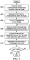
- FIG. 4 is a flow diagram of a method for multiple chirp generation in a radar device having a timing engine such as that of FIG. 3 , e.g., the radar device of FIG.2 .
- a timing engine such as that of FIG. 3
- the method is explained in reference to the radar device of Figs. 2 and 3 .
- embodiments of the method for other radar devices Further, embodiments are described assuming a timing engine with multiple chirp profiles.
- embodiments having a single chirp profile are examples of a single chirp profile.
- chirp configuration parameters are programmed 400 for each chirp in a frame of chirps to be transmitted. That is, for each chirp in the frame, software executing in the control component 226 programs (sets the values of) a set of chirp configuration parameters in the chirp configuration storage component 302. For example, if the frame includes 512 chirps, 512 sets of chirp configuration parameters are programmed.
- Chirp profile parameters in chirp profiles indicated in the programmed sets of chirp configuration parameters may also be programmed 402. That is, for each chirp profile indicated by a chirp profile select parameter in the programmed sets of chirp configuration parameters, the software programs the chirp profile parameters in that profile in the chirp profile storage component 304. This programming may include changing one, multiple, or all parameter values in the profile. Note that a chirp profile may be used by one, several, or all chirps in a frame. In some embodiments, this step is performed as needed. For example, the values of the parameters in a chirp profile may be used for transmission of multiple frames and thus not changed for each frame in which the profile is used. In another example, the chirp profiles may be programmed one time when the radar device is turned on and remain static during operation of the device.
- transmission of the frame of chirps is triggered 404. That is, the control component 226 signals the timing control component 306 to initiate the transmission of the frame of chirps. The timing control component 306 then iterates 406-412 through the sets of chirp configuration parameters stored in the chirp configuration storage component 302 to effect the transmission and reception of each specified chirp by the radar device 200.
- the timing control component 306 receives 406 the set of chirp configuration parameter values for the chirp from the chirp configuration storage component 302, receives 408 the chirp profile parameter values for the chirp from the chirp profile indicated by the chirp profile select parameter from the chirp profile storage component 304, and generates 410 control signals based on these parameter values to cause the chirp to be transmitted.
Landscapes
- Engineering & Computer Science (AREA)
- Radar, Positioning & Navigation (AREA)
- Remote Sensing (AREA)
- Computer Networks & Wireless Communication (AREA)
- Physics & Mathematics (AREA)
- General Physics & Mathematics (AREA)
- Radar Systems Or Details Thereof (AREA)
Applications Claiming Priority (3)
| Application Number | Priority Date | Filing Date | Title |
|---|---|---|---|
| US14/586,854 US9921295B2 (en) | 2014-12-30 | 2014-12-30 | Multiple chirp generation in a radar system |
| PCT/US2015/068077 WO2016109674A1 (fr) | 2014-12-30 | 2015-12-30 | Génération de chirps multiples dans un système radar |
| EP15876264.1A EP3262438B1 (fr) | 2014-12-30 | 2015-12-30 | Génération de chirps multiples dans un système radar |
Related Parent Applications (2)
| Application Number | Title | Priority Date | Filing Date |
|---|---|---|---|
| EP15876264.1A Division EP3262438B1 (fr) | 2014-12-30 | 2015-12-30 | Génération de chirps multiples dans un système radar |
| EP15876264.1A Division-Into EP3262438B1 (fr) | 2014-12-30 | 2015-12-30 | Génération de chirps multiples dans un système radar |
Publications (2)
| Publication Number | Publication Date |
|---|---|
| EP3889640A2 true EP3889640A2 (fr) | 2021-10-06 |
| EP3889640A3 EP3889640A3 (fr) | 2022-05-11 |
Family
ID=56163878
Family Applications (2)
| Application Number | Title | Priority Date | Filing Date |
|---|---|---|---|
| EP15876264.1A Active EP3262438B1 (fr) | 2014-12-30 | 2015-12-30 | Génération de chirps multiples dans un système radar |
| EP21157976.8A Pending EP3889640A3 (fr) | 2014-12-30 | 2015-12-30 | Génération de chirps multiples dans un système radar |
Family Applications Before (1)
| Application Number | Title | Priority Date | Filing Date |
|---|---|---|---|
| EP15876264.1A Active EP3262438B1 (fr) | 2014-12-30 | 2015-12-30 | Génération de chirps multiples dans un système radar |
Country Status (4)
| Country | Link |
|---|---|
| US (3) | US9921295B2 (fr) |
| EP (2) | EP3262438B1 (fr) |
| CN (2) | CN107110966B (fr) |
| WO (1) | WO2016109674A1 (fr) |
Families Citing this family (71)
| Publication number | Priority date | Publication date | Assignee | Title |
|---|---|---|---|---|
| US10725150B2 (en) | 2014-12-23 | 2020-07-28 | Infineon Technologies Ag | System and method for radar |
| US10317512B2 (en) | 2014-12-23 | 2019-06-11 | Infineon Technologies Ag | RF system with an RFIC and antenna system |
| US10061016B2 (en) | 2014-12-29 | 2018-08-28 | Texas Instruments Incorporated | Phase noise measurement in a cascaded radar system |
| US9853365B2 (en) * | 2015-05-05 | 2017-12-26 | Texas Instruments Incorporated | Dynamic programming of chirps in a frequency modulated continuous wave (FMCW) radar system |
| DE102015226443A1 (de) * | 2015-12-22 | 2017-06-22 | Robert Bosch Gmbh | Radarsensor, entsprechendes Betriebsverfahren und Fahrzeug |
| DE102016202936A1 (de) * | 2016-02-25 | 2017-08-31 | Robert Bosch Gmbh | Vorrichtung zum Ermitteln von Betriebsdaten für einen Radarsensor |
| US10181653B2 (en) | 2016-07-21 | 2019-01-15 | Infineon Technologies Ag | Radio frequency system for wearable device |
| US10218407B2 (en) | 2016-08-08 | 2019-02-26 | Infineon Technologies Ag | Radio frequency system and method for wearable device |
| US9964597B2 (en) | 2016-09-01 | 2018-05-08 | Texas Instruments Incorporated | Self test for safety logic |
| US10466772B2 (en) | 2017-01-09 | 2019-11-05 | Infineon Technologies Ag | System and method of gesture detection for a remote device |
| DE102017200706A1 (de) * | 2017-01-18 | 2018-07-19 | Robert Bosch Gmbh | Mehrfach unterabgetastetes Chirp-Sequence-Radar |
| US10505255B2 (en) | 2017-01-30 | 2019-12-10 | Infineon Technologies Ag | Radio frequency device packages and methods of formation thereof |
| US10602548B2 (en) | 2017-06-22 | 2020-03-24 | Infineon Technologies Ag | System and method for gesture sensing |
| US10630249B2 (en) | 2017-08-04 | 2020-04-21 | Texas Instruments Incorporated | Low power mode of operation for mm-wave radar |
| JP7033375B2 (ja) * | 2017-09-29 | 2022-03-10 | 株式会社デンソーテン | レーダ装置およびレーダ装置の調整方法 |
| US10746625B2 (en) | 2017-12-22 | 2020-08-18 | Infineon Technologies Ag | System and method of monitoring a structural object using a millimeter-wave radar sensor |
| US11346936B2 (en) | 2018-01-16 | 2022-05-31 | Infineon Technologies Ag | System and method for vital signal sensing using a millimeter-wave radar sensor |
| US11278241B2 (en) | 2018-01-16 | 2022-03-22 | Infineon Technologies Ag | System and method for vital signal sensing using a millimeter-wave radar sensor |
| US10795012B2 (en) | 2018-01-22 | 2020-10-06 | Infineon Technologies Ag | System and method for human behavior modelling and power control using a millimeter-wave radar sensor |
| US10576328B2 (en) | 2018-02-06 | 2020-03-03 | Infineon Technologies Ag | System and method for contactless sensing on a treadmill |
| EP3775972A1 (fr) * | 2018-03-26 | 2021-02-17 | Qualcomm Incorporated | Utilisation d'un canal de communication latérale pour échanger des informations radar afin d'améliorer la coexistence multi-radar |
| US11644529B2 (en) | 2018-03-26 | 2023-05-09 | Qualcomm Incorporated | Using a side-communication channel for exchanging radar information to improve multi-radar coexistence |
| US10705198B2 (en) | 2018-03-27 | 2020-07-07 | Infineon Technologies Ag | System and method of monitoring an air flow using a millimeter-wave radar sensor |
| US10775482B2 (en) | 2018-04-11 | 2020-09-15 | Infineon Technologies Ag | Human detection and identification in a setting using millimeter-wave radar |
| US10761187B2 (en) | 2018-04-11 | 2020-09-01 | Infineon Technologies Ag | Liquid detection using millimeter-wave radar sensor |
| US10794841B2 (en) | 2018-05-07 | 2020-10-06 | Infineon Technologies Ag | Composite material structure monitoring system |
| US10399393B1 (en) | 2018-05-29 | 2019-09-03 | Infineon Technologies Ag | Radar sensor system for tire monitoring |
| US10903567B2 (en) | 2018-06-04 | 2021-01-26 | Infineon Technologies Ag | Calibrating a phased array system |
| US11280876B2 (en) | 2018-06-18 | 2022-03-22 | Qualcomm Incorporated | Multi-radar coexistence using phase-coded frequency modulated continuous wave waveforms |
| US11385323B2 (en) | 2018-06-25 | 2022-07-12 | Qualcomm Incorporated | Selection of frequency modulated continuous wave (FMWC) waveform parameters for multi-radar coexistence |
| DE102018117202B3 (de) * | 2018-07-17 | 2020-01-23 | Infineon Technologies Ag | Radarsensor mit mehreren radar-chips |
| US11416077B2 (en) | 2018-07-19 | 2022-08-16 | Infineon Technologies Ag | Gesture detection system and method using a radar sensor |
| US11073598B2 (en) * | 2018-07-19 | 2021-07-27 | Qualcomm Incorporated | Time synchronized radar transmissions |
| US11585889B2 (en) * | 2018-07-25 | 2023-02-21 | Qualcomm Incorporated | Methods for radar coexistence |
| US10928501B2 (en) | 2018-08-28 | 2021-02-23 | Infineon Technologies Ag | Target detection in rainfall and snowfall conditions using mmWave radar |
| US11183772B2 (en) | 2018-09-13 | 2021-11-23 | Infineon Technologies Ag | Embedded downlight and radar system |
| US11125869B2 (en) | 2018-10-16 | 2021-09-21 | Infineon Technologies Ag | Estimating angle of human target using mmWave radar |
| US11397239B2 (en) * | 2018-10-24 | 2022-07-26 | Infineon Technologies Ag | Radar sensor FSM low power mode |
| US11360185B2 (en) | 2018-10-24 | 2022-06-14 | Infineon Technologies Ag | Phase coded FMCW radar |
| EP3654053A1 (fr) | 2018-11-14 | 2020-05-20 | Infineon Technologies AG | Emballage comportant un ou des dispositifs de détection acoustique et des éléments de détection à ondes millimétriques |
| US11087115B2 (en) | 2019-01-22 | 2021-08-10 | Infineon Technologies Ag | User authentication using mm-Wave sensor for automotive radar systems |
| US11355838B2 (en) | 2019-03-18 | 2022-06-07 | Infineon Technologies Ag | Integration of EBG structures (single layer/multi-layer) for isolation enhancement in multilayer embedded packaging technology at mmWave |
| US11126885B2 (en) | 2019-03-21 | 2021-09-21 | Infineon Technologies Ag | Character recognition in air-writing based on network of radars |
| US11782148B2 (en) * | 2019-03-25 | 2023-10-10 | Texas Instruments Incorporated | Radar system |
| US11454696B2 (en) | 2019-04-05 | 2022-09-27 | Infineon Technologies Ag | FMCW radar integration with communication system |
| CN110488228B (zh) * | 2019-07-11 | 2021-12-07 | 中国科学院电子学研究所 | 线性调频信号生成方法、装置及存储介质 |
| US11327167B2 (en) | 2019-09-13 | 2022-05-10 | Infineon Technologies Ag | Human target tracking system and method |
| US11774592B2 (en) | 2019-09-18 | 2023-10-03 | Infineon Technologies Ag | Multimode communication and radar system resource allocation |
| US11435443B2 (en) | 2019-10-22 | 2022-09-06 | Infineon Technologies Ag | Integration of tracking with classifier in mmwave radar |
| US11808883B2 (en) | 2020-01-31 | 2023-11-07 | Infineon Technologies Ag | Synchronization of multiple mmWave devices |
| US11614516B2 (en) | 2020-02-19 | 2023-03-28 | Infineon Technologies Ag | Radar vital signal tracking using a Kalman filter |
| US11585891B2 (en) | 2020-04-20 | 2023-02-21 | Infineon Technologies Ag | Radar-based vital sign estimation |
| US11567185B2 (en) | 2020-05-05 | 2023-01-31 | Infineon Technologies Ag | Radar-based target tracking using motion detection |
| US11774553B2 (en) | 2020-06-18 | 2023-10-03 | Infineon Technologies Ag | Parametric CNN for radar processing |
| US11704917B2 (en) | 2020-07-09 | 2023-07-18 | Infineon Technologies Ag | Multi-sensor analysis of food |
| US11614511B2 (en) | 2020-09-17 | 2023-03-28 | Infineon Technologies Ag | Radar interference mitigation |
| US11994575B2 (en) * | 2020-10-16 | 2024-05-28 | Texas Instruments Incorporated | Frequency modulated continuous wave radar system with interference mitigation |
| US11719787B2 (en) | 2020-10-30 | 2023-08-08 | Infineon Technologies Ag | Radar-based target set generation |
| US11719805B2 (en) | 2020-11-18 | 2023-08-08 | Infineon Technologies Ag | Radar based tracker using empirical mode decomposition (EMD) and invariant feature transform (IFT) |
| US12189021B2 (en) | 2021-02-18 | 2025-01-07 | Infineon Technologies Ag | Radar-based target tracker |
| US11662430B2 (en) | 2021-03-17 | 2023-05-30 | Infineon Technologies Ag | MmWave radar testing |
| US11950895B2 (en) | 2021-05-28 | 2024-04-09 | Infineon Technologies Ag | Radar sensor system for blood pressure sensing, and associated method |
| US12307761B2 (en) | 2021-08-06 | 2025-05-20 | Infineon Technologies Ag | Scene-adaptive radar |
| CN113985357B (zh) * | 2021-11-05 | 2025-07-04 | 中国航空工业集团公司雷华电子技术研究所 | 一种合成孔径雷达相干脉冲信号产生方法 |
| US12405351B2 (en) | 2022-03-25 | 2025-09-02 | Infineon Technologies Ag | Adaptive Tx-Rx crosstalk cancellation for radar systems |
| US20230350045A1 (en) * | 2022-04-27 | 2023-11-02 | Qualcomm Incorporated | Frequency modulated continuous wave signal-based positioning in new radio |
| US12399254B2 (en) | 2022-06-07 | 2025-08-26 | Infineon Technologies Ag | Radar-based single target vital sensing |
| US12399271B2 (en) | 2022-07-20 | 2025-08-26 | Infineon Technologies Ag | Radar-based target tracker |
| JP2024017802A (ja) * | 2022-07-28 | 2024-02-08 | 株式会社デンソー | レーダシステム、制御装置、制御方法、制御プログラム |
| US12254670B2 (en) | 2022-07-29 | 2025-03-18 | Infineon Technologies Ag | Radar-based activity classification |
| US12504526B2 (en) | 2022-09-21 | 2025-12-23 | Infineon Technologies Ag | Radar-based segmented presence detection |
Family Cites Families (19)
| Publication number | Priority date | Publication date | Assignee | Title |
|---|---|---|---|---|
| US5303079A (en) * | 1992-04-09 | 1994-04-12 | At&T Bell Laboratories | Tunable chirp, lightwave modulator for dispersion compensation |
| US5428361A (en) * | 1993-08-06 | 1995-06-27 | Rockwell International Corporation | Large time-bandwidth chirp pulse generator |
| US6091356A (en) * | 1998-10-05 | 2000-07-18 | Sensor Concepts Incorporated | Chirp source with rolling frequency lock for generating linear frequency chirps |
| US7110432B2 (en) * | 2002-01-14 | 2006-09-19 | Texas Instruments Incorporated | Orthogonal chirp modulation in multipath environments |
| US7482965B1 (en) * | 2004-12-17 | 2009-01-27 | Mayo Foundation For Medical Education And Research | Digital chirp waveform generator and method |
| GB0501043D0 (en) * | 2005-01-19 | 2005-06-01 | Smiths Group Plc | Radar apparatus |
| US7400290B2 (en) * | 2005-12-30 | 2008-07-15 | Valeo Raytheon Systems, Inc. | Vehicle radar system having multiple operating modes |
| US7345619B2 (en) * | 2005-12-30 | 2008-03-18 | Valeo Raytheon Systems, Inc. | Generating event signals in a radar system |
| WO2008144579A2 (fr) * | 2007-05-18 | 2008-11-27 | Sierra Monolithics, Inc. | Générateur à compression d'impulsions à synthèse fractionnaire-n |
| US8026843B2 (en) * | 2008-01-31 | 2011-09-27 | Infineon Technologies Ag | Radar methods and systems using ramp sequences |
| US20090290658A1 (en) * | 2008-05-22 | 2009-11-26 | George Moore | Multi-Pulse Signal Generator Based on a Sawtooth Chirp |
| GB2462148A (en) * | 2008-07-31 | 2010-02-03 | Mitsubishi Electric Inf Tech | Automotive FMCW radar with multiple frequency chirps |
| WO2010092438A1 (fr) * | 2009-02-13 | 2010-08-19 | Freescale Semiconductor, Inc. | Circuit intégré comprenant une circuiterie de génération de fréquence pour commander une source de fréquence |
| US9063225B2 (en) * | 2012-03-07 | 2015-06-23 | Toyota Motor Engineering & Manufacturing North America, Inc. | High resolution Doppler collision avoidance radar |
| ITTO20120417A1 (it) * | 2012-05-09 | 2013-11-10 | St Microelectronics Srl | Procedimento e dispositivi per elaborare segnali radar, ad esempio per sistemi di sicurezza stradale, relativo prodotto informatico |
| US10180496B2 (en) * | 2012-11-21 | 2019-01-15 | Nikon Corporation | Laser radar with remote local oscillator |
| EP2818887A1 (fr) * | 2013-06-26 | 2014-12-31 | Nxp B.V. | Émetteur-récepteur radar |
| US9172359B2 (en) * | 2014-03-04 | 2015-10-27 | Raytheon Company | Flexible chirp generator |
| CN103913742B (zh) * | 2014-04-25 | 2016-01-13 | 桂林电子科技大学 | 双接收天线的汽车防撞雷达系统及运行方法 |
-
2014
- 2014-12-30 US US14/586,854 patent/US9921295B2/en active Active
-
2015
- 2015-12-30 CN CN201580071620.7A patent/CN107110966B/zh active Active
- 2015-12-30 EP EP15876264.1A patent/EP3262438B1/fr active Active
- 2015-12-30 WO PCT/US2015/068077 patent/WO2016109674A1/fr not_active Ceased
- 2015-12-30 CN CN202010972717.8A patent/CN112098986B/zh active Active
- 2015-12-30 EP EP21157976.8A patent/EP3889640A3/fr active Pending
-
2018
- 2018-03-15 US US15/921,887 patent/US11262435B2/en active Active
-
2022
- 2022-01-13 US US17/574,680 patent/US11927690B2/en active Active
Also Published As
| Publication number | Publication date |
|---|---|
| EP3262438A1 (fr) | 2018-01-03 |
| US20160187462A1 (en) | 2016-06-30 |
| US9921295B2 (en) | 2018-03-20 |
| EP3262438A4 (fr) | 2018-05-02 |
| US20180203096A1 (en) | 2018-07-19 |
| CN107110966B (zh) | 2020-10-20 |
| US11927690B2 (en) | 2024-03-12 |
| US11262435B2 (en) | 2022-03-01 |
| EP3262438B1 (fr) | 2021-03-31 |
| WO2016109674A1 (fr) | 2016-07-07 |
| CN112098986B (zh) | 2024-06-25 |
| CN107110966A (zh) | 2017-08-29 |
| US20220137182A1 (en) | 2022-05-05 |
| EP3889640A3 (fr) | 2022-05-11 |
| CN112098986A (zh) | 2020-12-18 |
Similar Documents
| Publication | Publication Date | Title |
|---|---|---|
| US11927690B2 (en) | Multiple chirp generation in a radar system | |
| EP3292424B1 (fr) | Programmation dynamique de fluctuations de longueur d'onde dans un système radar fmcw | |
| US9800449B2 (en) | Frequency and time domain streaming receiver | |
| US12386035B2 (en) | Semiconductor chip and device and method for driving at least one channel for a radar signal | |
| US10110328B2 (en) | Apparatus and methods for calibrating analog circuitry in an integrated circuit | |
| JP6876191B2 (ja) | デジタル受信器/励振器のための多機能チャネル化/ddcアーキテクチャ | |
| EP3859376B1 (fr) | Synchronisation de multiples dispositifs à ondes millimétriques | |
| US20160277546A1 (en) | Frequency ramp generation | |
| US20200036398A1 (en) | Single clock timeshared channelizer circuit | |
| US12248088B2 (en) | Efficient programming model for real-time radar sequencing in a radar device | |
| CN104125179A (zh) | 一种基于fpga的多信号接收处理装置及其工作方法 | |
| CN104918321A (zh) | 一种卫星通信的射频收发处理装置及方法 | |
| JP3594812B2 (ja) | 信号受信装置 | |
| US6792060B1 (en) | Processor having an adaptable operational frequency | |
| Olvhammar | GNURadio-FFTS Documentation | |
| WO2013128228A1 (fr) | Procédé et système pour donner l'instruction à une unité de communication de réaliser un traitement prédéfini |
Legal Events
| Date | Code | Title | Description |
|---|---|---|---|
| PUAI | Public reference made under article 153(3) epc to a published international application that has entered the european phase |
Free format text: ORIGINAL CODE: 0009012 |
|
| STAA | Information on the status of an ep patent application or granted ep patent |
Free format text: STATUS: THE APPLICATION HAS BEEN PUBLISHED |
|
| AC | Divisional application: reference to earlier application |
Ref document number: 3262438 Country of ref document: EP Kind code of ref document: P |
|
| AK | Designated contracting states |
Kind code of ref document: A2 Designated state(s): AL AT BE BG CH CY CZ DE DK EE ES FI FR GB GR HR HU IE IS IT LI LT LU LV MC MK MT NL NO PL PT RO RS SE SI SK SM TR |
|
| RIC1 | Information provided on ipc code assigned before grant |
Ipc: G01S 7/35 20060101ALI20211104BHEP Ipc: G01S 13/34 20060101AFI20211104BHEP |
|
| PUAL | Search report despatched |
Free format text: ORIGINAL CODE: 0009013 |
|
| AK | Designated contracting states |
Kind code of ref document: A3 Designated state(s): AL AT BE BG CH CY CZ DE DK EE ES FI FR GB GR HR HU IE IS IT LI LT LU LV MC MK MT NL NO PL PT RO RS SE SI SK SM TR |
|
| RIC1 | Information provided on ipc code assigned before grant |
Ipc: G01S 7/35 20060101ALI20220404BHEP Ipc: G01S 13/34 20060101AFI20220404BHEP |
|
| STAA | Information on the status of an ep patent application or granted ep patent |
Free format text: STATUS: REQUEST FOR EXAMINATION WAS MADE |
|
| 17P | Request for examination filed |
Effective date: 20221111 |
|
| RBV | Designated contracting states (corrected) |
Designated state(s): AL AT BE BG CH CY CZ DE DK EE ES FI FR GB GR HR HU IE IS IT LI LT LU LV MC MK MT NL NO PL PT RO RS SE SI SK SM TR |
|
| STAA | Information on the status of an ep patent application or granted ep patent |
Free format text: STATUS: EXAMINATION IS IN PROGRESS |
|
| 17Q | First examination report despatched |
Effective date: 20250530 |
|
| R17C | First examination report despatched (corrected) |
Effective date: 20250721 |