EP3889779A1 - Verfahren zur handhabung eines gleichzeitigen ausfalls aller kanäle eines mehrkanal-motorreglers für eine gasturbine - Google Patents
Verfahren zur handhabung eines gleichzeitigen ausfalls aller kanäle eines mehrkanal-motorreglers für eine gasturbine Download PDFInfo
- Publication number
- EP3889779A1 EP3889779A1 EP21153610.7A EP21153610A EP3889779A1 EP 3889779 A1 EP3889779 A1 EP 3889779A1 EP 21153610 A EP21153610 A EP 21153610A EP 3889779 A1 EP3889779 A1 EP 3889779A1
- Authority
- EP
- European Patent Office
- Prior art keywords
- channel
- processor
- engine controller
- gas turbine
- resetting
- Prior art date
- Legal status (The legal status is an assumption and is not a legal conclusion. Google has not performed a legal analysis and makes no representation as to the accuracy of the status listed.)
- Granted
Links
Images




Classifications
-
- F—MECHANICAL ENGINEERING; LIGHTING; HEATING; WEAPONS; BLASTING
- F02—COMBUSTION ENGINES; HOT-GAS OR COMBUSTION-PRODUCT ENGINE PLANTS
- F02C—GAS-TURBINE PLANTS; AIR INTAKES FOR JET-PROPULSION PLANTS; CONTROLLING FUEL SUPPLY IN AIR-BREATHING JET-PROPULSION PLANTS
- F02C9/00—Controlling gas-turbine plants; Controlling fuel supply in air- breathing jet-propulsion plants
-
- G—PHYSICS
- G05—CONTROLLING; REGULATING
- G05B—CONTROL OR REGULATING SYSTEMS IN GENERAL; FUNCTIONAL ELEMENTS OF SUCH SYSTEMS; MONITORING OR TESTING ARRANGEMENTS FOR SUCH SYSTEMS OR ELEMENTS
- G05B9/00—Safety arrangements
- G05B9/02—Safety arrangements electric
- G05B9/03—Safety arrangements electric with multiple-channel loop, i.e. redundant control systems
-
- G—PHYSICS
- G06—COMPUTING OR CALCULATING; COUNTING
- G06F—ELECTRIC DIGITAL DATA PROCESSING
- G06F11/00—Error detection; Error correction; Monitoring
- G06F11/07—Responding to the occurrence of a fault, e.g. fault tolerance
- G06F11/0703—Error or fault processing not based on redundancy, i.e. by taking additional measures to deal with the error or fault not making use of redundancy in operation, in hardware, or in data representation
- G06F11/0706—Error or fault processing not based on redundancy, i.e. by taking additional measures to deal with the error or fault not making use of redundancy in operation, in hardware, or in data representation the processing taking place on a specific hardware platform or in a specific software environment
- G06F11/0736—Error or fault processing not based on redundancy, i.e. by taking additional measures to deal with the error or fault not making use of redundancy in operation, in hardware, or in data representation the processing taking place on a specific hardware platform or in a specific software environment in functional embedded systems, i.e. in a data processing system designed as a combination of hardware and software dedicated to performing a certain function
- G06F11/0739—Error or fault processing not based on redundancy, i.e. by taking additional measures to deal with the error or fault not making use of redundancy in operation, in hardware, or in data representation the processing taking place on a specific hardware platform or in a specific software environment in functional embedded systems, i.e. in a data processing system designed as a combination of hardware and software dedicated to performing a certain function in a data processing system embedded in automotive or aircraft systems
-
- G—PHYSICS
- G06—COMPUTING OR CALCULATING; COUNTING
- G06F—ELECTRIC DIGITAL DATA PROCESSING
- G06F11/00—Error detection; Error correction; Monitoring
- G06F11/07—Responding to the occurrence of a fault, e.g. fault tolerance
- G06F11/0703—Error or fault processing not based on redundancy, i.e. by taking additional measures to deal with the error or fault not making use of redundancy in operation, in hardware, or in data representation
- G06F11/0793—Remedial or corrective actions
-
- F—MECHANICAL ENGINEERING; LIGHTING; HEATING; WEAPONS; BLASTING
- F05—INDEXING SCHEMES RELATING TO ENGINES OR PUMPS IN VARIOUS SUBCLASSES OF CLASSES F01-F04
- F05D—INDEXING SCHEME FOR ASPECTS RELATING TO NON-POSITIVE-DISPLACEMENT MACHINES OR ENGINES, GAS-TURBINES OR JET-PROPULSION PLANTS
- F05D2260/00—Function
- F05D2260/80—Diagnostics
-
- F—MECHANICAL ENGINEERING; LIGHTING; HEATING; WEAPONS; BLASTING
- F05—INDEXING SCHEMES RELATING TO ENGINES OR PUMPS IN VARIOUS SUBCLASSES OF CLASSES F01-F04
- F05D—INDEXING SCHEME FOR ASPECTS RELATING TO NON-POSITIVE-DISPLACEMENT MACHINES OR ENGINES, GAS-TURBINES OR JET-PROPULSION PLANTS
- F05D2270/00—Control
- F05D2270/01—Purpose of the control system
- F05D2270/09—Purpose of the control system to cope with emergencies
- F05D2270/094—Purpose of the control system to cope with emergencies by using back-up controls
-
- F—MECHANICAL ENGINEERING; LIGHTING; HEATING; WEAPONS; BLASTING
- F05—INDEXING SCHEMES RELATING TO ENGINES OR PUMPS IN VARIOUS SUBCLASSES OF CLASSES F01-F04
- F05D—INDEXING SCHEME FOR ASPECTS RELATING TO NON-POSITIVE-DISPLACEMENT MACHINES OR ENGINES, GAS-TURBINES OR JET-PROPULSION PLANTS
- F05D2270/00—Control
- F05D2270/01—Purpose of the control system
- F05D2270/09—Purpose of the control system to cope with emergencies
- F05D2270/095—Purpose of the control system to cope with emergencies by temporary overriding set control limits
-
- G—PHYSICS
- G06—COMPUTING OR CALCULATING; COUNTING
- G06F—ELECTRIC DIGITAL DATA PROCESSING
- G06F11/00—Error detection; Error correction; Monitoring
- G06F11/07—Responding to the occurrence of a fault, e.g. fault tolerance
- G06F11/16—Error detection or correction of the data by redundancy in hardware
- G06F11/20—Error detection or correction of the data by redundancy in hardware using active fault-masking, e.g. by switching out faulty elements or by switching in spare elements
- G06F11/202—Error detection or correction of the data by redundancy in hardware using active fault-masking, e.g. by switching out faulty elements or by switching in spare elements where processing functionality is redundant
- G06F11/2035—Error detection or correction of the data by redundancy in hardware using active fault-masking, e.g. by switching out faulty elements or by switching in spare elements where processing functionality is redundant without idle spare hardware
-
- G—PHYSICS
- G06—COMPUTING OR CALCULATING; COUNTING
- G06F—ELECTRIC DIGITAL DATA PROCESSING
- G06F11/00—Error detection; Error correction; Monitoring
- G06F11/07—Responding to the occurrence of a fault, e.g. fault tolerance
- G06F11/16—Error detection or correction of the data by redundancy in hardware
- G06F11/20—Error detection or correction of the data by redundancy in hardware using active fault-masking, e.g. by switching out faulty elements or by switching in spare elements
- G06F11/202—Error detection or correction of the data by redundancy in hardware using active fault-masking, e.g. by switching out faulty elements or by switching in spare elements where processing functionality is redundant
- G06F11/2038—Error detection or correction of the data by redundancy in hardware using active fault-masking, e.g. by switching out faulty elements or by switching in spare elements where processing functionality is redundant with a single idle spare processing component
Definitions
- the present subject matter relates generally to a method for handling a simultaneous failure of all channels of a multi-channel engine controller configured to control operation of a gas turbine engine. More specifically, the present subject matter is directed to a method for resetting each channel of the multi-channel engine controller without experiencing a lapse in control of the gas turbine engine.
- a gas turbine engine on an aircraft generally includes, in serial flow, a compressor section, a combustion section, a turbine section and an exhaust section.
- air enters an inlet of the compressor section where one or more compressors progressively compress the air until it reaches the combustion section.
- Fuel is mixed with the compressed air and burned within the combustion section to provide combustion gases.
- the combustion gases are then routed from the combustion section through a hot gas path defined within the turbine section and exhausted from the turbine section via the exhaust section.
- Typical engine controllers can have dual channels to provide redundancy.
- typical engine controllers can include a first processor associated with a first channel of the engine controller and a second processor associated with a second channel of the engine controller.
- the two channels e.g., first channel and second channel
- the two channels may operate in an active/standby mode where one channel is active and in control while the other channel is in standby and ready to assume control if needed.
- the two channels may operate in an active/active mode where both channels are in control.
- the two channels may operate in a mixed mode where the engine controller implements an active/standby scheme and an active/active scheme.
- both the first channel and the second channel may each simultaneously experience one or more fault conditions (e.g., software exceptions).
- both the first processor and the second processor may reset at the same time. This is undesirable, because resetting both the first processor and the second processor at the same time leaves no processor available to control operation of the gas turbine engine.
- the present disclosure is directed to a method for handling a simultaneous failure of all channels of a multi-channel engine controller configured to control operation of a gas turbine engine.
- the method includes obtaining, by a first processor associated with a first channel of the engine controller, data indicative of the simultaneous failure of all channels of the engine controller.
- the method further includes providing, by the first processor, one or more control signals associated with resetting at least a second processor associated with a second channel of the multi-channel engine controller based, at least in part, on the data.
- the method includes controlling, by the first processor, operation of the gas turbine engine while at least the second processor is resetting.
- the present disclosure is directed to a multi-channel engine controller configured to control operation of a gas turbine engine.
- the multi-channel engine controller includes a plurality of processors. Each of the plurality of processors is associated with a corresponding channel of the multi-channel engine controller.
- a first processor associated with a first channel of the multi-channel engine controller is configured to obtain data indicative of a simultaneous failure of all channels of the multi-channel engine controller.
- the first processor is further configured to provide one or more control signals associated with resetting at least a second processor associated with a second channel of the multi-channel engine controller based, at least in part, on the data.
- the first processor is further configured to control operation of the gas turbine engine while at least the second processor is resetting.
- first and second may be used interchangeably to distinguish one component from another and are not intended to signify location or importance of the individual components.
- the term “about” may refer to within 10% of a stated numerical value.
- Example aspects of the present disclosure are directed to a multi-channel engine controller configured to control operation of a gas turbine engine. More specifically, the present disclosure is directed to methods for handling a simultaneous failure of all channels of the multi-channel engine controller. As will be discussed below in more detail, the multi-channel engine controller can be configured to recover from the simultaneous failure of all channels of the engine controller such that an amount of time during which the multi-channel engine controller is offline and unavailable to control operation of the gas turbine engine is reduced or eliminated.
- a first processor associated with a first channel of the engine controller can be configured to obtain data indicative of the simultaneous failure of all channels of the multi-channel engine controller.
- the first processor can simultaneously obtain data indicative of one or more fault conditions (e.g., software exceptions) associated with the first channel and one or more fault conditions associated with at least a second channel of the multi-channel engine controller.
- the first processor can be further configured to determine whether the first channel is healthier than every other channel (e.g., at least the second channel) of the multi-channel engine controller based, at least in part, on the data indicative of the one or more fault conditions associated with the first channel and the one or more fault conditions associated with every other channel (e.g., at least the second channel) of the multi-channel engine controller.
- the first processor can compare one or more fault conditions associated with the first channel to one or more fault conditions associated with every other channel (e.g., at least the second channel) of the multi-channel engine controller. For instance, in some implementations, the first processor can be configured to determine the first channel is healthier than every other channel of the multi-channel engine controller when a total number of the fault conditions associated with the first channel is less than a total number of fault conditions associated with each of the remaining channels (e.g., at least the second channel) of the multi-channel engine controller.
- the first processor can be configured to determine another channel (e.g., the second channel) is healthier than the first channel when the total number of the fault conditions associated with the first channel is greater than the total number of fault conditions associated with another channel (e.g., the second channel) of the multi-channel engine controller.
- another channel e.g., the second channel
- the first processor can be configured to provide one or more control signals to at least a second processor associated with the second channel of the engine controller in response to determining the first channel is healthier than every other channel of the multi-channel engine controller. More specifically, the one or more control signals can be associated with resetting the second processor. In this manner, the second processor can be configured to reset (e.g., reinitialize, reboot, etc.) itself in response to receiving the one or more control signals from the first processor.
- the first processor can be further configured to configure itself in a safe mode in response to determining the first channel is healthier than every other channel of the multi-channel engine controller.
- the first processor can be configured to perform only critical functions necessary to provide uniform control of the gas turbine engine while the multi-channel engine controller is recovering from the simultaneous failure of all channels of the multi-channel engine controller.
- the first processor can be configured to control operation of one or more actuators (e.g., torque motor, fuel metering solenoid valve, etc.) of the gas turbine engine while the first processor is configured in the safe mode. It should be understood that the first processor executes a limited set of computer-implemented instructions when the first processor is configured in the safe mode.
- actuators e.g., torque motor, fuel metering solenoid valve, etc.
- the second processor can be configured to reset itself upon receiving the one or more control signals provided via the first processor. Furthermore, when the second processor resets itself, the second processor can be configured to determine whether the one or more fault conditions associated with the second channel still exist. When the second processor determines the one or more fault conditions associated with the second channel no longer exist, the second processor can provide data to the first processor to indicate the second channel has recovered from the one or more fault conditions associated with the second channel. For instance, in some implementations, the data can be one or more control signals associated with resetting the first processor. Upon receiving the one or more control signals from the second processor, the first processor can be configured to reset itself.
- the second processor can be configured to control operation of the gas turbine engine. It should be appreciated that the second processor can be configured to operate in a normal operating mode (e.g., not the safe operating mode) since the second processor was previously reset to clear the one or more fault conditions associated with the second channel. In this manner, the gas turbine engine can operate normally (e.g., not in the safe mode) while the first processor is being reset to clear the one or more fault conditions associated with the first channel. As will be discussed below in more detail, in some instances an initial reset of the second processor may not result in the one or more fault conditions associated with the second channel being cleared.
- a normal operating mode e.g., not the safe operating mode
- the gas turbine engine can operate normally (e.g., not in the safe mode) while the first processor is being reset to clear the one or more fault conditions associated with the first channel.
- an initial reset of the second processor may not result in the one or more fault conditions associated with the second channel being cleared.
- the second processor can be configured to reboot itself again and subsequently check to see if the one or more fault conditions associated with the second channel still exist. It should be appreciated that, in some implementations, the second processor can be configured to reset itself a predetermined number of times. If the one or more fault conditions associated with the second channel still exist after the second processor has reset itself the predetermined number of times, the one or more fault conditions associated with the second channel can be considered non-recoverable fault conditions. In this manner, the second channel cannot be brought back online.
- the first processor can be configured to reset itself while configured in the safe mode to clear the one or more fault conditions associated with the first channel. It should be appreciated that the first processor can be configured to reset itself within a predetermined amount of time to minimize an amount of time the first processor is offline and therefore unavailable to control operation of the gas turbine engine. For instance, in some implementations, the predetermined amount of time can range from about 2 milliseconds to about 5 milliseconds. In this manner, the engine controller can be configured to handle simultaneous failure of all channels of the engine controller occurring during critical portions of a flight, such as during vertical takeoff and landing.
- FIG. 1 provides a perspective view of an exemplary aerial vehicle 10 in accordance with the present disclosure.
- the aerial vehicle 10 can include a cockpit 20.
- the cockpit 20 can include an instrument panel (not shown) having one or more input devices that can be used to control operation of the aerial vehicle 10.
- the aerial vehicle 10 can include a gas turbine engine 100.
- the aerial vehicle 10 is depicted as having only one gas turbine engine 100, it should be appreciated that, in some implementations, the aerial vehicle 10 can include multiple (e.g., two or more) gas turbine engine.
- the aerial vehicle 10 can include an engine control system 200 configured to control operation of the gas turbine engine 100.
- the aerial vehicle 10 can include any suitable type of aerial vehicle 10.
- the aerial vehicle 10 can be a high speed compound rotary-wing aircraft with supplemental translational thrust systems, dual contra-rotating, coaxial rotor system aircraft, turboprops, tilt-rotors, tilt-wing aircraft, conventional take-off and landing aircraft and other turbine driven machines will also benefit from the present disclosure.
- FIG. 2 provides a schematic cross-sectional view of the gas turbine engine 100 in accordance with the present disclosure.
- the gas turbine engine 100 defines a longitudinal or centerline axis 102 extending through for reference.
- the gas turbine engine 100 generally includes a substantially tubular outer casing 104 that defines an annular inlet 106.
- the outer casing 104 may be formed from a single casing or multiple casings.
- the outer casing 104 encloses, in serial flow relationship, a gas generator compressor 110, a combustion section 130, a turbine 140, and an exhaust section 150.
- the gas generator compressor 110 includes an annular array of inlet guide vanes 112, one or more sequential stages of compressor blades 114, one or more sequential stages of one or more stages of variable vanes 116, one or more sequential stages of one or more stationary compressor vanes 117, and a centrifugal compressor 118.
- the compressor blades 114, variable vanes 116, stationary compressor vanes 117, and the centrifugal compressor 118 define a compressed air path 120.
- the combustion section 130 includes a combustion chamber 132 and one or more fuel nozzles 134 extending into the combustion chamber 132.
- the fuel nozzles 134 supply fuel to mix with compressed air entering the combustion chamber 132. Further, the mixture of fuel and compressed air combust within the combustion chamber 132 to form combustion gases 136. As will be described below in more detail, the combustion gases 136 drive both the gas generator compressor 110 and the turbine 140.
- the turbine 140 includes a gas generator turbine 142 and a power turbine 144.
- the gas generator turbine 142 includes one or more sequential stages of turbine rotor blades 146 and one or more sequential stages of stator vanes 147.
- the power turbine 144 includes one or more sequential stages of turbine rotor blades 148 and one or more sequential stages of stator vanes 149.
- the gas generator turbine 142 drives the gas generator compressor 110 via a gas generator shaft 160
- the power turbine 144 drives an output shaft 180 via a power turbine shaft 170.
- the gas generator compressor 110 and the gas generator turbine 142 are coupled to one another via the gas generator shaft 160.
- the combustion gases 136 drive both the gas generator turbine 142 and the power turbine 144.
- the gas generator turbine 142 rotates around the centerline axis 102
- the gas generator compressor 110 and the gas generator shaft 160 both rotate around the centerline axis 102.
- the power turbine shaft 170 rotates and transfers rotational energy to the output shaft 180.
- the gas turbine engine 100 may be the first and second gas turbine engines 60, 62 of FIG. 1
- the output shaft 180 may rotate both the main rotor blades 44 and the tail rotor blades 54 of the aerial vehicle 10.
- gas turbine engine e.g., turboshaft gas turbine engine
- turboshaft gas turbine engine any suitable type of gas turbine engine will benefit from the present disclosure.
- the gas turbine engine can be a turbofan gas turbine engine.
- the gas turbine engine can be a turboprop gas turbine engine.
- FIG. 3 an example embodiment of the engine control system 200 for controlling the operation of the gas turbine engine 100 ( FIG. 2 ) is provided.
- the engine control system 200 will be described with reference to the aerial vehicle 10 and the gas turbine engine 100 described above with reference to FIGS. 1 and 2 , respectively.
- the engine control system 200 can be implemented or used in association with any other suitable aerial vehicle and/or any other suitable gas turbine engine.
- the engine control system 200 can include an engine controller 202 configured to control operation of the gas turbine engine 100.
- the engine controller 202 can control operation of the gas turbine engine 100 via a fuel controller 206. It should be appreciated, however, that in some implementations, the engine controller 202 can control operation of the gas turbine engine 100 without any intervening components (e.g., fuel controller 206)..
- the engine controller 202 can generally include one or more processor(s) 210 and associated memory 212 configured to perform a variety of computer-implemented functions (e.g., performing the methods, steps, calculations and the like disclosed herein). Additionally, the fuel controller 206 can include one or more processor(s) 220 and associated memory 222 configured to perform a variety of computer-implemented functions. It should be appreciated, however, that the fuel controller 206 can, in some implementations, be programmable logic devices, such as a Field Programmable Gate Array (FPGA).
- FPGA Field Programmable Gate Array
- processor refers not only to integrated circuits referred to in the art as being included in a computer, but also refers to a controller, microcontroller, a microcomputer, a programmable logic controller (PLC), an application specific integrated circuit (ASIC), a Field Programmable Gate Array (FPGA), and other programmable circuits.
- PLC programmable logic controller
- ASIC application specific integrated circuit
- FPGA Field Programmable Gate Array
- the memory 212, 222 may generally include memory element(s) including, but not limited to, computer readable medium (e.g., random access memory (RAM)), computer readable non-volatile medium (e.g., flash memory), a compact disc-read only memory (CD-ROM), a magneto-optical disk (MOD), a digital versatile disc (DVD) and/or other suitable memory elements or combinations thereof.
- computer readable medium e.g., random access memory (RAM)
- computer readable non-volatile medium e.g., flash memory
- CD-ROM compact disc-read only memory
- MOD magneto-optical disk
- DVD digital versatile disc
- the engine controller 202 can include a communications interface module 214.
- the communications interface module 214 can include associated electronic circuitry that is used to send and receive data. More specifically, the communications interface module 214 of the engine controller 202 can be used to send and receive data to and from the fuel controller 206. It should be appreciated that the communications interface module 214 may be any combination of suitable wired or wireless communications interfaces.
- the engine controller 202 can be in communication with one or more sensor(s) 230 of the gas turbine engine 100.
- the one or more sensor(s) 230 can include, without limitation, a pressure sensor, a temperature sensor, a torque sensor, and a speed sensor.
- the pressure sensor may be configured to sense an ambient pressure (P0) or an inlet pressure (PI) at the gas generator compressor 110 ( FIG. 2 ), and the temperature sensor may be configured to sense an inlet temperature (T1) at the gas generator compressor 110.
- the pressure sensor can be configured to sense a discharge pressure (P S3 ) at the outlet of the gas generator compressor 110, and the temperature sensor may be configured to sense a turbine gas temperature (T 4.5 ) within the turbine 140.
- the torque sensor may be configured to detect an engine torque (Q1) of the gas turbine engine 100.
- the speed sensor may be configured to detect a rotational speed NG of the gas generator shaft 160.
- the speed sensor can be configured to detect a rotational speed N P of the power turbine shaft 170.
- the one or more sensor(s) 230 of the gas turbine engine 100 can include any combination of the sensors (e.g., pressure, temperature, torque, speed) mentioned above.
- the engine controller 202 can be communicatively coupled to the one or more sensor(s) 230 of the gas turbine engine 100 via a wired connection.
- the engine controller 202 can receive data (e.g., analog or digital) from the one or more sensor(s) 230 of the gas turbine engine 100 via the wired connection.
- the fuel controller 206 can include a communications interface module 224.
- the communications interface module 224 can include associated electronic circuitry that is used to send and receive data to and from the engine controller 202. It should be appreciated that the communications interface module 224 may be any suitable wired or wireless communications interface.
- the fuel controller 206 can be in communication with one or more actuators 240 of the gas turbine engine 100.
- the one or more actuators 240 can include at least one of a torque motor and a fuel metering solenoid valve. It should be appreciated, however, that the fuel controller 206 can be in communication with any suitable type of actuators of the gas turbine engine 100.
- the engine controller 202 can be a dual-channel system with two redundant channels, a first channel A and a second redundant channel B. It should be appreciated, however, that the engine controller 202 can include more than two channels. For instance, in some implementations, the engine controller 202 can include three or more channels. In this manner, the engine controller 202 can be at least a triple redundant system.
- channels A and B may provide redundancy in the engine control and operation.
- the first channel A and the second redundant channel B of the engine controller 202 can include the processor 210, the memory 212, and the communications interface module 214.
- the first channel A and the second redundant channel B of the fuel controller 206 can include the processor 220, the memory 222, and the communication interface module 224.
- the engine controller 202 can be configured to handle a simultaneous failure of all channels (e.g., first channel A, second channel B) of the engine controller 202 according to example embodiments of the present disclosure.
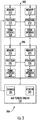
- the multi-channel engine controller can include at least a first channel 310 and a second channel 320. It should be appreciated, however, that the multi-channel engine controller can have more than two channels. For instance, in some implementations, the multi-channel engine controller can include three or more channels.
- the multi-channel engine controller can include a processor associated with each channel of thereof.
- the multi-channel engine controller can include a first processor 330 associated with the first channel 310 and a second processor 340 associated with the second channel 320.
- the multi-channel engine controller can, when controlling operation of a gas turbine engine of an aerial vehicle, experience a simultaneous failure of all channels (e.g., first channel 310 and second channel 320) of the multi-channel engine controller.
- the first processor 330 associated with the first channel 310 and the second processor 340 associated with the second channel 320 can each simultaneously experience one or more fault conditions (e.g., software exceptions).
- the multi-channel engine controller can be configured to recover from the simultaneous failure of all channels of the multi-channel engine controller without compromising control of the aerial vehicle.
- the first processor 330 can be configured to obtain data indicative of the simultaneous failure of all channels (e.g., at least the first channel 310 and the second channel 320) of the multi-channel engine controller. For example, the first processor 330 can simultaneously obtain data indicative of one or more fault conditions associated with each channel of the multi-channel engine controller. For instance, the first processor 330 can obtain data indicative of one or more fault conditions associated with the first channel 310 and one or more fault conditions associated with the second channel 320.
- the first processor 330 can be configured to determine whether the first channel is healthier than every other channel (e.g., at least the second channel 320) of the multi-channel engine controller based, at least in part, on the data indicative of the one or more fault conditions associated with each channel (e.g., at least the first channel 310 and the second channel 320). For instance, the first processor 330 can be configured to compare the one or more fault conditions associated with the first processor 330 to the one or more fault conditions associated with the second processor 340.
- the first processor 330 can be configured to determine the first processor 330 is healthier than the second processor 340 when a total number of the fault conditions associated with the first processor 330 is less than a total number of the fault conditions associated with the second processor 340. Conversely, the first processor 330 can be configured to determine the second processor 340 is healthier than the first processor 330 when the total number of the fault conditions associated with the first processor 330 is greater than the total number of fault conditions associated with the second processor 340.
- the first processor 330 can be configured to provide one or more control signals 360 to the second processor 340 in response to determining the first channel 310 is healthier than every other channel (e.g., at least the second channel 320) of the multi-channel engine controller. More specifically, the one or more control signals can be associated with resetting at least the second processor 340. In this manner, the second processor 340 can be configured to reset (e.g., reinitialize, reboot, etc.) itself in response to receiving the one or more control signals from the first processor 330.
- the first processor 330 can be further configured to configure itself in a safe mode 380 in response to determining the first channel 310 is healthier than every other channel (e.g., at least the second channel 320) of the multi-channel engine controller.
- control capabilities of the first processor 330 can be limited.
- the first processor 330 can be configured to perform only critical functions necessary to provide uniform control of the gas turbine engine while the multi-channel engine controller is recovering from the simultaneous failure of all channels thereof.
- One example of a critical function can include, without limitation, monitoring one or more watchdog timers associated with the first processor 330.
- the first processor 330 can be configured to control operation of the one or more actuators 240 ( FIG. 3 ) of the gas turbine engine while the first processor 330 is configured in the safe mode 380.
- the first processor 330 can be configured to control operation of the one or more actuators 240 to provide control of critical functions while executing a limited set of computer-implementable instructions (e.g., software).
- Examples of the one or more actuators 240 can include at least one of a torque motor and a fuel metering solenoid valve. It should be appreciated, however, that the first processor 330 can be configured to control any suitable actuator associated with the gas turbine engine.
- the second processor 340 can be configured to reset itself upon receiving the one or more control signals 360 provided via the first processor 330.
- the second processor 340 can be configured to determine whether the one or more fault conditions associated with the second processor 340 still exist.
- the second processor 340 can provide data to the first processor 330 to indicate the second channel 320 has recovered from the one or more fault conditions.
- the data can include one or more control signals 370 associated with resetting the first processor 330. It should be appreciated that the first processor 330 can, upon receiving the data, be configured to reset itself.
- the second processor 340 can be configured to control operation of the gas turbine engine. It should be appreciated that the second processor 340 can be configured to operate in a normal operating mode 382 (e.g., not the safe mode 380) since the second processor 340 was previously reset to clear the one or more fault conditions associated with the second channel 320. In this manner, the gas turbine engine can operate normally while the first processor 330 is being reset to clear the one or more fault conditions associated with the first channel 310. As shown, both the first processor 330 and the second processor 340 can be configured to operate in the normal operating mode 382 when the first processor 330 resets itself and successfully clears the or more fault conditions associated with the first channel 310. As will be discussed below in more detail, an initial reset of the second processor 340 may not, in some instances, result in the one or more fault conditions associated with the second channel 320 being cleared.
- a normal operating mode 382 e.g., not the safe mode 380
- the second processor 340 when the second processor 340 determines the one or more fault conditions associated with the second channel 320 still exist after the initial reset, the second processor 340 can be configured to reboot itself again and subsequently check again to see if the one or more fault conditions associated with the second channel 320 still exist. It should be appreciated that the second processor 340 can be configured to reset itself a predetermined number of times. If the one or more fault conditions associated with the second processor 340 still exist after the second processor 340 has reset itself the predetermined number of times, the one or more fault conditions associated with the second processor 340 can be considered non-recoverable fault conditions. In this manner, the second channel 320 cannot be brought back online.
- the first processor 330 can be configured to reset itself while configured in the safe mode 380 to clear the one or more fault conditions associated with the first channel 310. It should be appreciated that the first processor 330 can be configured to reset itself within a predetermined amount of time to minimize an amount of time the first processor 330 is offline and therefore unavailable to control operation of the gas turbine engine. For instance, in some implementations, the predetermined amount of time can range from about 2 milliseconds to about 5 milliseconds. In this manner, the engine controller can be configured to handle a simultaneous failure of all channels of the engine controller during critical portions of a flight, such as during vertical takeoff and landing where loss of control of the gas turbine engine cannot exceed 12 milliseconds.
- FIG. 6 a flow diagram of a method 500 for handling a simultaneous failure of all channels of a multi-channel engine controller configured to control operation of a gas turbine engine is provided according to example embodiments of the present disclosure.
- the method 500 will be discussed herein with reference to the multi-channel engine controller described above with reference to FIGS. 4 and 5 .
- the disclosed method 500 may generally be implemented with gas turbine engines having any other suitable engine configuration and/or with systems having any other suitable system configuration.
- FIG. 6 depicts steps performed in a particular order for purposes of illustration and discussion, the methods discussed herein are not limited to any particular order or arrangement.
- steps of the methods disclosed herein can be omitted, rearranged, combined, and/or adapted in various ways without deviating from the scope of the present disclosure.
- the method 500 can include obtaining, by a first processor associated with a first channel of the engine controller, data indicative of the simultaneous failure of all channels of the multi-channel engine controller.
- the first processor can obtain data indicative of one or more fault conditions associated with each channel of the multi-channel engine controller.
- the method 500 can include determining, by the first processor, the first channel is healthier than every other channel of the multi-channel engine controller.
- the first processor can be configured to compare the one or more fault conditions associated with the first channel to the one or more fault conditions associated with every other channel (e.g., at least the second channel) of the multi-channel engine controller. More specifically, the first processor can be configured to determine the first channel is healthier than every other channel of the multi-channel engine controller when a total number of fault conditions associated with the first channel is less than a total number of fault conditions associated with each of the remaining channels (e.g., at least the second channel) of the multi-channel engine controller.
- the method 500 can include providing, by the first processor, one or more control signals associated with resetting at least a second processor associated with a second channel of the multi-channel engine controller based, at least in part, on the data obtained at (502).
- providing the one or more control signals associated with resetting at least the second processor associated with the second channel of the multi-channel engine controller in response to determining the first channel is healthier than every other channel (e.g., at least the second channel) of the multi-channel engine controller at (504).
- the method 500 can include controlling, by the first processor, operation of the gas turbine engine while resetting at least the second processor to attempt to resolve (e.g., clear) the one or more fault conditions associated with at least the second channel of the multi-channel engine controller.
- the first processor can be configured in a safe mode to control operation of the gas turbine engine at (508).
- the first processor can be configured to operation of one or more actuators of the gas turbine engine such that operation of the gas turbine engine is uniform (e.g., constant) while resetting at least the second processor associated with the second channel of the multi-channel engine controller.
- the method 500 can include determining, by the second processor, whether resetting at least the second processor resolved (e.g., cleared) the one or more fault conditions associated with the second channel. If the second processor determines resetting the second processor resolved the one or more fault conditions associated with the second channel, the method 500 proceeds to (512). Otherwise, the method 500 proceeds to (516).
- the method 500 can include providing, by the second processor, one or more control signals associated with resetting the first processor to resolve (e.g., clear) the one or more fault conditions associated with the first channel.
- the method 500 can include controlling, by the second processor, operation of the gas turbine engine while resetting the first processor. It should be understood that the second processor is not configured in the safe mode while controlling operation of the gas turbine engine since the one or more fault condition associated with the second channel were previously resolved by resetting the second processor at (506). In this manner, the multi-channel engine controller can maintain control of the aerial vehicle while recovering from the simultaneous failure of all channels thereof.
- the method 500 can include determining, by the second processor, whether at least the second processor has been reset a predetermined number of times. If the number of times at least the second processor has been reset is equal to the predetermined number of times, the method proceeds to (518). Otherwise, at least the second processor resets and the method 500 reverts to (516).
- the method 500 can include determining, by the first processor, at least the second channel is offline and proceeding to (520).
- the method 500 can include resetting the first processor within a predetermined amount of time.
- the predetermined amount of time can range from about 1 millisecond to about 5 milliseconds.
- engine controllers implementing the method 500 according to the present disclosure can be implemented on aerial vehicles capable of vertical takeoffs and landings, because the multi-channel engine controller can recover from a simultaneous failure of all channels thereof without losing control of operation of the gas turbine engine for more than 12 milliseconds.
Landscapes
- Engineering & Computer Science (AREA)
- Theoretical Computer Science (AREA)
- General Engineering & Computer Science (AREA)
- Physics & Mathematics (AREA)
- General Physics & Mathematics (AREA)
- Quality & Reliability (AREA)
- Chemical & Material Sciences (AREA)
- Combustion & Propulsion (AREA)
- Mechanical Engineering (AREA)
- Automation & Control Theory (AREA)
- Control Of Turbines (AREA)
- Safety Devices In Control Systems (AREA)
Applications Claiming Priority (1)
| Application Number | Priority Date | Filing Date | Title |
|---|---|---|---|
| US16/833,870 US11720067B2 (en) | 2020-03-30 | 2020-03-30 | Method for handling a simultaneous failure of all channels of a multi-channel engine controller for a gas turbine engine |
Publications (2)
| Publication Number | Publication Date |
|---|---|
| EP3889779A1 true EP3889779A1 (de) | 2021-10-06 |
| EP3889779B1 EP3889779B1 (de) | 2026-05-06 |
Family
ID=74285315
Family Applications (1)
| Application Number | Title | Priority Date | Filing Date |
|---|---|---|---|
| EP21153610.7A Active EP3889779B1 (de) | 2020-03-30 | 2021-01-26 | Verfahren zur handhabung eines gleichzeitigen ausfalls aller kanäle eines mehrkanal-motorreglers für eine gasturbine |
Country Status (3)
| Country | Link |
|---|---|
| US (1) | US11720067B2 (de) |
| EP (1) | EP3889779B1 (de) |
| CN (1) | CN113530688B (de) |
Families Citing this family (2)
| Publication number | Priority date | Publication date | Assignee | Title |
|---|---|---|---|---|
| DE102022206796B4 (de) * | 2022-07-04 | 2025-02-13 | Robert Bosch Gesellschaft mit beschränkter Haftung | Vorrichtung, Verfahren, Computerprogramm zur sicheren hoch-verfügbaren Übertragung von Nachrichten, Fahrzeug das die Vorrichtung umfasst |
| US12509236B1 (en) | 2024-06-28 | 2025-12-30 | Pratt & Whitney Canada Corp. | Control assembly for aircraft propulsion systems |
Citations (4)
| Publication number | Priority date | Publication date | Assignee | Title |
|---|---|---|---|---|
| US20060200278A1 (en) * | 2005-03-02 | 2006-09-07 | Honeywell International Inc. | Generic software fault mitigation |
| EP1835404A2 (de) * | 2006-03-15 | 2007-09-19 | Fujitsu Limited | Elektronische Vorrichtung zur Fehlerdetektion |
| US20180212858A1 (en) * | 2017-01-26 | 2018-07-26 | Schweitzer Engineering Laboratories, Inc. | Systems and Methods for Selection Between Multiple Redundant Data Streams |
| US20180349235A1 (en) * | 2017-06-01 | 2018-12-06 | The University Of Akron | Redundant computer system utilizing comparison diagnostics and voting techniques |
Family Cites Families (23)
| Publication number | Priority date | Publication date | Assignee | Title |
|---|---|---|---|---|
| US4821193A (en) * | 1985-08-26 | 1989-04-11 | General Electric Company | Digital control for gas turbine engine |
| DE19919504B4 (de) | 1999-04-29 | 2005-10-20 | Mtu Aero Engines Gmbh | Triebwerksregler, Triebwerk und Verfahren zum Regeln eines Triebwerks |
| US6813527B2 (en) | 2002-11-20 | 2004-11-02 | Honeywell International Inc. | High integrity control system architecture using digital computing platforms with rapid recovery |
| US8051031B2 (en) | 2008-02-06 | 2011-11-01 | The Boeing Company | Metadata for software aircraft parts |
| US8055393B2 (en) | 2008-02-06 | 2011-11-08 | The Boeing Company | Method and apparatus for loading software aircraft parts |
| WO2010056241A1 (en) | 2008-11-13 | 2010-05-20 | Sikorsky Aircraft Corporation | Adaptive fail-fixed system for fadec controlled gas turbine engines |
| CN101923508B (zh) | 2009-06-12 | 2012-12-19 | 中兴通讯股份有限公司 | 一种嵌入式系统中的异常处理方法及装置 |
| US9483032B2 (en) * | 2011-09-22 | 2016-11-01 | Hamilton Sundstrand Corporation | Multi-channel protection logic |
| US8806579B1 (en) | 2011-10-12 | 2014-08-12 | The Boeing Company | Secure partitioning of devices connected to aircraft network data processing systems |
| FR2995947B1 (fr) * | 2012-09-26 | 2018-03-16 | Safran Aircraft Engines | Procede de differenciation de pannes de commande dans un systeme de commande d'un actionneur, notamment de stator de moteur a turbine a gaz |
| FR3003365B1 (fr) | 2013-03-12 | 2015-04-10 | Airbus Operations Sas | Procede et dispositif de gestion de mises a jour logicielles d'un ensemble d'equipements d'un systeme tel qu'un systeme d'un aeronef |
| US9772615B2 (en) * | 2013-05-06 | 2017-09-26 | Hamilton Sundstrand Corporation | Multi-channel control switchover logic |
| FR3010854B1 (fr) | 2013-09-13 | 2015-10-09 | Airbus Operations Sas | Equipement avionique reconfigurable et methode de reconfiguration d'un tel equipement. |
| US9382011B2 (en) * | 2014-04-10 | 2016-07-05 | Pratt & Whitney Canada Corp. | Multiple aircraft engine control system and method of communicating data therein |
| ES2835575T3 (es) | 2014-05-11 | 2021-06-22 | Safetty Systems Ltd | Una unidad de monitorización, así como un método para predecir el funcionamiento anormal de sistemas de ordenador activados por tiempo |
| FR3025626B1 (fr) * | 2014-09-05 | 2017-11-03 | Sagem Defense Securite | Architecture bi-voies avec liaisons ccdl redondantes |
| US10060358B2 (en) * | 2016-04-19 | 2018-08-28 | General Electric Company | Compressor bleed valve health assessment systems and methods |
| US10234917B2 (en) | 2016-06-03 | 2019-03-19 | Hewlett Packard Enterprise Development Lp | Sequential resets of redundant subsystems with random delays |
| US10371002B2 (en) * | 2016-06-14 | 2019-08-06 | General Electric Company | Control system for a gas turbine engine |
| US10099796B2 (en) * | 2016-10-04 | 2018-10-16 | General Electric Company | System and method for dynamically controlling the operation of an aircraft |
| US10302020B2 (en) * | 2016-12-12 | 2019-05-28 | General Electric Company | System and method for controlling a fuel flow to a gas turbine engine |
| US10571914B2 (en) * | 2017-06-29 | 2020-02-25 | The Boeing Company | Fault coverage for multiple failures in redundant systems |
| US11203950B2 (en) * | 2018-01-25 | 2021-12-21 | Raytheon Technologies Corporation | On-board estimator engine sensor fault accommodation in engine control |
-
2020
- 2020-03-30 US US16/833,870 patent/US11720067B2/en active Active
-
2021
- 2021-01-26 EP EP21153610.7A patent/EP3889779B1/de active Active
- 2021-01-29 CN CN202110125542.1A patent/CN113530688B/zh active Active
Patent Citations (4)
| Publication number | Priority date | Publication date | Assignee | Title |
|---|---|---|---|---|
| US20060200278A1 (en) * | 2005-03-02 | 2006-09-07 | Honeywell International Inc. | Generic software fault mitigation |
| EP1835404A2 (de) * | 2006-03-15 | 2007-09-19 | Fujitsu Limited | Elektronische Vorrichtung zur Fehlerdetektion |
| US20180212858A1 (en) * | 2017-01-26 | 2018-07-26 | Schweitzer Engineering Laboratories, Inc. | Systems and Methods for Selection Between Multiple Redundant Data Streams |
| US20180349235A1 (en) * | 2017-06-01 | 2018-12-06 | The University Of Akron | Redundant computer system utilizing comparison diagnostics and voting techniques |
Also Published As
| Publication number | Publication date |
|---|---|
| CN113530688A (zh) | 2021-10-22 |
| CN113530688B (zh) | 2024-08-20 |
| EP3889779B1 (de) | 2026-05-06 |
| US20210301734A1 (en) | 2021-09-30 |
| US11720067B2 (en) | 2023-08-08 |
Similar Documents
| Publication | Publication Date | Title |
|---|---|---|
| US10099796B2 (en) | System and method for dynamically controlling the operation of an aircraft | |
| US10006375B1 (en) | Propulsion system for an aircraft | |
| US11015480B2 (en) | Feed forward load sensing for hybrid electric systems | |
| EP3960997A1 (de) | Abschaltung und wiederanlassen eines hybrid-elektrischen triebwerks während des flugs | |
| EP2356327B1 (de) | Adaptives system mit integrierter sicherheit für fadec-gesteuerte gasturbinentriebwerke | |
| US11618580B2 (en) | Hybrid electric aircraft engine | |
| US9915201B2 (en) | Aircraft power system | |
| EP3715964B1 (de) | Verteilte steuermodule mit eingebauten tests und steuerungserhaltenden fehlerreaktionen | |
| JP2002517667A (ja) | シャフト破損検出装置 | |
| EP3677511B1 (de) | Systeme und verfahren zur steuerung der lastverteilung und geschwindigkeit von motoren in mehrmotorantriebssystemen | |
| US12253030B2 (en) | In-flight engine re-start | |
| CN104271923B (zh) | 包括具有用于执行涡轮机保护功能的模块的监视系统的涡轮机和监视方法 | |
| US20240425188A1 (en) | Testing secondary power system of aircraft powerplant | |
| EP3889779B1 (de) | Verfahren zur handhabung eines gleichzeitigen ausfalls aller kanäle eines mehrkanal-motorreglers für eine gasturbine | |
| US11661895B2 (en) | Autonomous safety mode for distributed control of turbomachines | |
| EP3656661B1 (de) | Integrierte propeller- und motorsteuerung | |
| EP4273040A1 (de) | Systeme und verfahren zur geräuschsteuerung in flugzeugen mit hybrid-elektrischem gasturbinentriebwerk | |
| WO2018063575A1 (en) | System and method for controlling fuel flow to a gas turbine engine based on motion sensor data | |
| EP4484728A1 (de) | Flugzeugtriebwerk mit mehreren unabhängigen kraftstoffsystemen | |
| US12631525B2 (en) | Testing secondary power system of aircraft powerplant | |
| EP4484727A1 (de) | Testen eines sekundärstromsystems eines flugzeugtriebwerks | |
| EP4368814A1 (de) | Systeme und verfahren zur steuerung von strebenpositionen für eine strebenanordnung eines flugzeugantriebssystems |
Legal Events
| Date | Code | Title | Description |
|---|---|---|---|
| PUAI | Public reference made under article 153(3) epc to a published international application that has entered the european phase |
Free format text: ORIGINAL CODE: 0009012 |
|
| STAA | Information on the status of an ep patent application or granted ep patent |
Free format text: STATUS: THE APPLICATION HAS BEEN PUBLISHED |
|
| AK | Designated contracting states |
Kind code of ref document: A1 Designated state(s): AL AT BE BG CH CY CZ DE DK EE ES FI FR GB GR HR HU IE IS IT LI LT LU LV MC MK MT NL NO PL PT RO RS SE SI SK SM TR |
|
| STAA | Information on the status of an ep patent application or granted ep patent |
Free format text: STATUS: REQUEST FOR EXAMINATION WAS MADE |
|
| 17P | Request for examination filed |
Effective date: 20220406 |
|
| RBV | Designated contracting states (corrected) |
Designated state(s): AL AT BE BG CH CY CZ DE DK EE ES FI FR GB GR HR HU IE IS IT LI LT LU LV MC MK MT NL NO PL PT RO RS SE SI SK SM TR |
|
| STAA | Information on the status of an ep patent application or granted ep patent |
Free format text: STATUS: EXAMINATION IS IN PROGRESS |
|
| 17Q | First examination report despatched |
Effective date: 20220927 |
|
| RIC1 | Information provided on ipc code assigned before grant |
Ipc: G06F 11/14 20060101AFI20250606BHEP Ipc: G06F 11/16 20060101ALI20250606BHEP Ipc: G06F 11/07 20060101ALI20250606BHEP Ipc: G06F 11/20 20060101ALN20250606BHEP |
|
| GRAP | Despatch of communication of intention to grant a patent |
Free format text: ORIGINAL CODE: EPIDOSNIGR1 |
|
| STAA | Information on the status of an ep patent application or granted ep patent |
Free format text: STATUS: GRANT OF PATENT IS INTENDED |
|
| INTG | Intention to grant announced |
Effective date: 20250728 |
|
| GRAJ | Information related to disapproval of communication of intention to grant by the applicant or resumption of examination proceedings by the epo deleted |
Free format text: ORIGINAL CODE: EPIDOSDIGR1 |
|
| STAA | Information on the status of an ep patent application or granted ep patent |
Free format text: STATUS: EXAMINATION IS IN PROGRESS |
|
| GRAP | Despatch of communication of intention to grant a patent |
Free format text: ORIGINAL CODE: EPIDOSNIGR1 |
|
| STAA | Information on the status of an ep patent application or granted ep patent |
Free format text: STATUS: GRANT OF PATENT IS INTENDED |
|
| INTC | Intention to grant announced (deleted) | ||
| RIC1 | Information provided on ipc code assigned before grant |
Ipc: G06F 11/14 20060101AFI20251111BHEP Ipc: G06F 11/16 20060101ALI20251111BHEP Ipc: G06F 11/07 20060101ALI20251111BHEP Ipc: G06F 11/20 20060101ALN20251111BHEP |
|
| INTG | Intention to grant announced |
Effective date: 20251201 |
|
| GRAS | Grant fee paid |
Free format text: ORIGINAL CODE: EPIDOSNIGR3 |
|
| GRAA | (expected) grant |
Free format text: ORIGINAL CODE: 0009210 |
|
| STAA | Information on the status of an ep patent application or granted ep patent |
Free format text: STATUS: THE PATENT HAS BEEN GRANTED |
|
| RAP3 | Party data changed (applicant data changed or rights of an application transferred) |
Owner name: GENERAL ELECTRIC COMPANY |
|
| AK | Designated contracting states |
Kind code of ref document: B1 Designated state(s): AL AT BE BG CH CY CZ DE DK EE ES FI FR GB GR HR HU IE IS IT LI LT LU LV MC MK MT NL NO PL PT RO RS SE SI SK SM TR |
|
| REG | Reference to a national code |
Ref country code: CH Ref legal event code: F10 Free format text: ST27 STATUS EVENT CODE: U-0-0-F10-F00 (AS PROVIDED BY THE NATIONAL OFFICE) Effective date: 20260506 Ref country code: GB Ref legal event code: FG4D |