EP3890141A1 - Procédé et dispositif d'invitation à la charge, terminal mobile, et support d'informations lisible par ordinateur - Google Patents
Procédé et dispositif d'invitation à la charge, terminal mobile, et support d'informations lisible par ordinateur Download PDFInfo
- Publication number
- EP3890141A1 EP3890141A1 EP18942452.6A EP18942452A EP3890141A1 EP 3890141 A1 EP3890141 A1 EP 3890141A1 EP 18942452 A EP18942452 A EP 18942452A EP 3890141 A1 EP3890141 A1 EP 3890141A1
- Authority
- EP
- European Patent Office
- Prior art keywords
- charger
- type
- cumulative number
- mobile terminal
- determining
- Prior art date
- Legal status (The legal status is an assumption and is not a legal conclusion. Google has not performed a legal analysis and makes no representation as to the accuracy of the status listed.)
- Withdrawn
Links
Images

Classifications
-
- G—PHYSICS
- G06—COMPUTING OR CALCULATING; COUNTING
- G06F—ELECTRIC DIGITAL DATA PROCESSING
- G06F13/00—Interconnection of, or transfer of information or other signals between, memories, input/output devices or central processing units
- G06F13/10—Program control for peripheral devices
- G06F13/102—Program control for peripheral devices where the program performs an interfacing function, e.g. device driver
-
- H—ELECTRICITY
- H02—GENERATION; CONVERSION OR DISTRIBUTION OF ELECTRIC POWER
- H02J—ELECTRIC POWER NETWORKS; CIRCUIT ARRANGEMENTS OR SYSTEMS FOR SUPPLYING OR DISTRIBUTING ELECTRIC POWER; SYSTEMS FOR STORING ELECTRIC ENERGY
- H02J7/00—Circuit arrangements for charging or discharging batteries or for supplying loads from batteries
- H02J7/40—Circuit arrangements for charging or discharging batteries or for supplying loads from batteries characterised by the exchange of charge or discharge related data
- H02J7/42—Circuit arrangements for charging or discharging batteries or for supplying loads from batteries characterised by the exchange of charge or discharge related data with electronic devices having internal batteries, e.g. mobile phones
-
- G—PHYSICS
- G06—COMPUTING OR CALCULATING; COUNTING
- G06F—ELECTRIC DIGITAL DATA PROCESSING
- G06F13/00—Interconnection of, or transfer of information or other signals between, memories, input/output devices or central processing units
- G06F13/38—Information transfer, e.g. on bus
- G06F13/42—Bus transfer protocol, e.g. handshake; Synchronisation
- G06F13/4282—Bus transfer protocol, e.g. handshake; Synchronisation on a serial bus, e.g. I2C bus, SPI bus
-
- H—ELECTRICITY
- H02—GENERATION; CONVERSION OR DISTRIBUTION OF ELECTRIC POWER
- H02J—ELECTRIC POWER NETWORKS; CIRCUIT ARRANGEMENTS OR SYSTEMS FOR SUPPLYING OR DISTRIBUTING ELECTRIC POWER; SYSTEMS FOR STORING ELECTRIC ENERGY
- H02J7/00—Circuit arrangements for charging or discharging batteries or for supplying loads from batteries
- H02J7/40—Circuit arrangements for charging or discharging batteries or for supplying loads from batteries characterised by the exchange of charge or discharge related data
-
- H—ELECTRICITY
- H02—GENERATION; CONVERSION OR DISTRIBUTION OF ELECTRIC POWER
- H02J—ELECTRIC POWER NETWORKS; CIRCUIT ARRANGEMENTS OR SYSTEMS FOR SUPPLYING OR DISTRIBUTING ELECTRIC POWER; SYSTEMS FOR STORING ELECTRIC ENERGY
- H02J7/00—Circuit arrangements for charging or discharging batteries or for supplying loads from batteries
- H02J7/40—Circuit arrangements for charging or discharging batteries or for supplying loads from batteries characterised by the exchange of charge or discharge related data
- H02J7/47—Arrangements for checking compatibility or authentication between one component, e.g. a battery or a battery charger, and another component, e.g. a power source
-
- G—PHYSICS
- G06—COMPUTING OR CALCULATING; COUNTING
- G06F—ELECTRIC DIGITAL DATA PROCESSING
- G06F2213/00—Indexing scheme relating to interconnection of, or transfer of information or other signals between, memories, input/output devices or central processing units
- G06F2213/0042—Universal serial bus [USB]
-
- H—ELECTRICITY
- H02—GENERATION; CONVERSION OR DISTRIBUTION OF ELECTRIC POWER
- H02J—ELECTRIC POWER NETWORKS; CIRCUIT ARRANGEMENTS OR SYSTEMS FOR SUPPLYING OR DISTRIBUTING ELECTRIC POWER; SYSTEMS FOR STORING ELECTRIC ENERGY
- H02J7/00—Circuit arrangements for charging or discharging batteries or for supplying loads from batteries
Definitions
- the present disclosure relates to the field of terminals, and in particular to a recharging prompting method, a device, a mobile terminal, and a computer-readable storage medium.
- the mobile terminal may be detached from a power cable, and may be movable and portable.
- the mobile terminal can be charged at anytime and anywhere, such that the mobile terminal may be even more portable.
- the present disclosure may provide a recharging prompting method, a device, a mobile terminal, and a computer-readable storage medium.
- a prompt may be generated when a charger in an un-recommended type is frequently used to charge a mobile terminal.
- a charging prompting method includes following operations.
- a type of a charger is determined.
- a cumulative number of times of the charger in the type being connected is updated.
- a prompt is generated in response to the cumulative number of times of a charger in a non-recommended type reaching a predetermined number of times.
- a charging prompting apparatus includes following components.
- a determination module is configured to determine a type of a charger when the charger is connected.
- An updating module is configured to update a cumulative number of times of the type of the charger being connected.
- a prompting module is configured to prompt in response to a cumulative number of times of a charger in a non-recommended type reaching a predetermined number of times.
- a mobile terminal includes a memory, a processor, and a computer program.
- the computer program is stored in the memory and is capable of being executed by the processor.
- the processor executes the computer program, the processor is configured to perform the operations as described in the first aspect of the present disclosure.
- a computer-readable storage medium stores a computer program.
- the computer program is executed by a processor to perform the operations as described in the first aspect.
- a computer program product includes a computer program.
- the computer program is executed by one or more processors to perform the operations as described in the first aspect.
- the present embodiment provides a charging prompting method that may be applied to any mobile terminal having a rechargeable battery that needs to be charged, such as a mobile phone, a tablet computer, a laptop, a smart bracelet, a personal digital assistant, and other mobile terminals.
- a rechargeable battery in any type may be provided according to actual needs, such as, a lithium-ion battery.
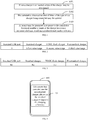
- the charging prompting method of the present embodiment may include following operations.
- a type of the charger may be determined.
- a charger whose output voltage and current are within a range of a charging voltage and current supported by the mobile terminal may be connected for charging the mobile terminal.
- the operation S101 may include following operations.
- an ID of the charger may be obtained.
- the type of the charger may be determined based on the ID of the charger.
- an ID resistor i.e. an identification resistor, an IDR
- a resistance value of the ID resistor may the ID of the charger.
- the ID of the charger may be obtained by obtaining the resistance value of the ID resistor of the charger.
- ID resistors having different resistance values may be embedded in different types of chargers. The type of the charger may be determined based on the resistance value of the ID resistor of the charger.
- the operation S1012 may include following operations.
- a value range in which the ID of the charger falls may be determined based on the ID of the charger.
- the type of the charger may be determined based on the value range in which the ID of the charger falls.
- a resistance value range of the ID resistor embedded in a standard type of charger adapting to the mobile terminal may be constant. It may be determined whether the charger is in the standard type, based on the value range in which the ID of the charger falls.
- the method may include following operations.
- the type of the charger is a standard USB port for a PC client in response to the ID of the charger being 0.
- the type of the charger is the standard charger in response to the ID of the charger being within a value range of an ID of the standard charger.
- the type of the charger is a non-standard charger in response to the ID of the charger being within a value range of an ID of the non-standard charger.
- a charger in a non-recommended type may include the standard USB port for the PC client and the non-standard charger.
- a charging circuit corresponding to the standard USB port (SDP) of the PC (Personal Computer) client does not include the ID resistor. Therefore, in response to the ID of the charger being 0, the type of the charger may be determined as the standard USB port of the PC client.
- the standard charger (Dedicated Charging Port, DCP) may be a charger provided by the manufacturer adapting to the mobile terminal, or a charger having same parameters as the charger provided by the manufacturer adapting to the mobile terminal.
- the non-standard charger (Other Charging Port, OCP) may be a charger having different parameters from the charger provided by the manufacture adapting to the mobile terminal.
- the standard charger may be a charger in a recommended type.
- the recommended type of charger may ensure a charging efficiency and charging stability, and may be adapted for the mobile terminal.
- the non-recommended type of charger may have a low charging efficiency and poor charging stability.
- the operation S10122 may further include following operations.
- the type of the charger may be a VOOC flash charger, in response to the ID of the charger being within a value range of an ID of the VOOC flash charger.
- VOOC flash charger VOOC Charging Port, VCP
- VCP VOOC Charging Port
- the method may include following operations.
- a correspondence relationship may be established between a value range corresponding to the ID of each of different types of chargers and the type of the charger.
- the operation S10122 may include following operations.
- the type of the charger may be determined based on the value range in which the ID of the charger falls and the correspondence relationship.
- the correspondence relationship may be a mapping relationship.
- the mapping relationship may be represented in a form of a correspondence table or a displayed look-up-table (LUT, look-up-table).
- the mapping relationship may be implemented by other data tables or Random Access Memory (RAM)-type storage media that have the same function as the displayed look-up-table for input data, i.e., looking up the corresponding output data based on the input data.
- RAM Random Access Memory
- a correspondence table indicating the correspondence relationship is exemplarily illustrated.
- a value 0 may correspond to the standard USB port of the PC client.
- a first value range may correspond to the standard charger.
- a second value range may correspond to the VOOC flash charger.
- a third value range may correspond to the non-standard charger.
- the cumulative number of times of the type of the charger being connected may be updated.
- the cumulative number of times of the certain type of charger may be updated.
- the method may include following operations.
- a statistical table for counting the cumulative number of times of each of different types of chargers being connected may be created.
- the operation S102 may include following operations.
- the cumulative number of times of the type of the charger in the statistical table may be updated.
- the statistical table may be a one-dimensional array or a two-dimensional table.
- a tuple of the two-dimensional table may be cumulative numbers of times of chargers in different types, and attribute of the two-dimensional table may be the type of the charger.
- the cumulative numbers of times of different types of chargers may be arranged into the one-dimensional array in any order.
- the cumulative numbers of times of each type of charger may be arranged in an order of: the standard USB port for the PC client, the standard charger, the VOOC flash charger, and the non-standard charger.
- the one-dimensional array ⁇ 1, 3, 5, 2 ⁇ may indicate that the cumulative number of times of the standard USB port for the PC client may be 1, the cumulative number of times of the standard charger may be 3, the cumulative number of times of the VOOC flash charger may be 5, and the cumulative number of times of the non-standard charger may be 2.
- the standard USB port of the PC client may correspond to a value N1.
- the standard charger may correspond to a value N2.
- the VOOC flash charger may correspond to a value N3.
- the non-standard charger may correspond to a value N4.
- Each of the N1, the N2, the N3, and the N4 may be an integer greater than or equal to 0 and less than or equal to a predetermined number of times.
- the operation S1021 may include following operations.
- the cumulative number of times corresponding to the type of the charger in the statistical table may be added by 1.
- the mobile terminal may be connected to a certain type of charger once, i.e. a value of the cumulative number of the certain type in the statistical table may be added by 1.
- the method may include following operations.
- timing may be started.
- timing may be terminated.
- the operation S102 may include following operations.
- the cumulative number of times of the type of the charger being connected may be updated in response to a duration of the timing being longer than a predetermined duration.
- the charging when the mobile terminal is connected to a charger in a certain type for charging for a period of time longer than the predetermined duration, the charging may be determined as charging performed by a user actively and consciously. In this case, the cumulative number of times of the certain type may be updated.
- the charging When the mobile terminal is connected to the charger in the certain type for charging for a period of time shorter than or equal to the predetermined duration, the charging may be determined as charging performed by a user unconsciously. In this case, the cumulative number of times of the certain type may not be updated.
- the predetermined duration may be set to be any effective charging duration based on actual demands, for example, any time length between 100s (seconds) to 500s, such as, 300s.
- a prompt may be generated in response to the cumulative number of times of the charger in the non-recommended type reaching a predetermined number of times.
- the prompt in response to the cumulative number of times of the non-recommended type of charger reaching the predetermined number of times, it may indicate that the user may frequently use the non-standard charger or the standard USB port of the PC client to charge the mobile terminal, having a low charging efficiency and poor charging stability.
- the prompt may be generated to suggest the user to use the standard charger to charge the mobile terminal.
- the prompt may be achieved by a pop-up window, a short message or voice. Specific content of the prompt may be set according to the actual needs, as long as the user may be reminded not to use the non-standard charger too frequently but suggested to use the standard charger.
- the content of the prompt may be: "XX detects that you often use the non-standard charger/the USB port of the PC client charging, please use the standard charger to improve the charging efficiency".
- the XX may be a name of the mobile terminal or a name of a voice assistant.
- a pop-up window is shown on a display interface of a mobile terminal 400 showing the prompt content.
- the prompt content displayed in the pop-up window 401 may be "XX detects that you often use the non-standard charger/the USB port of the PC client charging, please use the standard charger to improve the charging efficiency".
- the predetermined number of times may be set according to actual needs, for example, any number between 5 and 30, such as, 20.
- the operation S103 may include following operations.
- a prompt reminding the user to use the charger in the recommended type may be generated.
- the method may include following operations.
- the cumulative numbers of times for all types of chargers may be cleared.
- the cumulative history numbers of times for the non-recommended type of charger may be cleared.
- the cumulative numbers of times for all types of chargers may be cleared, or the cumulative numbers of times for the non-recommended types of chargers may be cleared.
- the cumulative number of times for each type of charger connected to the mobile terminal may be re-counted.
- the charging prompting method may further include following operations.
- a prompt for reminding the user to use the VOOC flash charger may be generated.
- the prompt in response to the cumulative number of times for the non-VOOC flash charger reaching the predetermined number of times, the prompt may be generated to suggest the user to use the VOOC flash charger to charge the mobile terminal to improve the charging efficiency and charging stability.
- the user may be reminded by the prompt in any forms, such as the pop-up window, the short message or the voice.
- Specific content of the prompt may be set according to actual needs, as long as the user is reminded to use the VOOC flash charger.
- the prompt content may be: "XX detects that you often use the non-standard charger/the USB port for the PC client/the non-VOOC flash charger for charging, please use the VOOC flash charger to improve the charging efficiency".
- the XX may be the name of the mobile terminal or the name of the voice assistant.
- the charging prompting method may further include following operations.
- the cumulative numbers of times of the charger in the recommended type reaching the predetermined number of times may be cleared, or the cumulative number of times of the recommended type of charger may be cleared.
- the cumulative numbers of times of all types of chargers may be cleared, or the cumulative number of times of the non-recommended type of charger may be cleared.
- the cumulative number of times of each type of charger connected to the mobile terminal may be re-counted.
- the charging prompting method may include following operations.
- the cumulative number of times of any type of charger may be cleared in response to the cumulative number of any type of charger not reaching the predetermined number of times.
- the predetermined period of time may be set according to actual needs, for example, any number of days between 30 to 90 days, for example, 60 days.
- the method may include following operations.
- the type of the charger may be determined.
- the method may include following operations.
- the method may further include following operations.
- the system of the mobile terminal may turn on the prompting function by default.
- the system may update and record the cumulative number of times that the charger is connected to the mobile terminal by default in response to the mobile terminal being connected for charging.
- the system may provide the corresponding prompt in response to the cumulative number of times reaching the predetermined number of times.
- the user may turn off the prompting function by any human-machine interaction.
- the system may stop updating and recording the cumulative number of times, and may not provide the corresponding prompt in response to the cumulative number of times reaching the predetermined number of times.
- a button for turning on and off the prompting function may be set on a system setting interface of the mobile terminal, a main interface or a main body of the mobile terminal to allow the prompting function to be turned on and off by a one-touch operation.
- the type of the charger may be determined.
- the number of times of each of different types of chargers connected to the mobile terminal may be counted respectively.
- the prompt may be generated to remind the user to use the recommended type of charger in response to the mobile terminal being connected to the charger in the non-recommended type for too many times. In this way, the user may be assisted to improve the charging efficiency, enhance charging stability and extend the battery life.
- serial numbers of the operations in the above embodiments do not imply an order of execution, and the order of execution of the operations should be determined by its function and intrinsic logic, and shall not limit a process of performing the embodiments of the present disclosure.
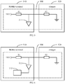
- the detection circuit 500 may include a dividing resistor R1 and an analog-to-digital converter 511 configured in the mobile terminal 510.
- the detection circuit 500 may also include a resistor R2 configured in a charger 520.
- the resistor R2 may be the ID resistor corresponding to the ID of the charger 520.
- connection between various components in the detection circuit 500 may be shown as follows.
- An end of the dividing resistor R1 may be connected to a reference voltage VREF.
- the other end of the dividing resistor R1 may be electrically connected to an input end of the analog-to-digital converter 511 and an end of the resistor R2.
- the other end of the resistor R2 may be connected to the ground.
- the operation S101 of the Embodiment 1 may include following operations.
- the resistance value of the resistor corresponding to the ID of the charger may be obtained based on the reference voltage, a voltage output from an output end of the analog-to-digital converter, and a resistance value of the dividing resistor.
- the resistance value of the resistor corresponding to the ID of the charger may be equal to the ID of the charger.
- the R ch arg er_id may indicate the resistance value of the resistor corresponding to the ID of the charger.
- the R pull_up may indicate the resistance value of the dividing resistor.
- the U adc may indicate the voltage output from the output end of the analog-to-digital converter.
- the U ref may indicate the reference voltage.
- the detection circuit 500 may further include a processor 512, connected to the output end of the analog-to-digital converter 511.
- the processor may be configured to obtain the reference voltage, the voltage output from the output end of the analog-to-digital converter and the resistance value of the dividing resistor.
- the processor may be configured to calculate the resistance value of the resistor corresponding to the ID of the charger based on the reference voltage, the voltage output from the output end of the analog-to-digital converter and the resistance value of the dividing resistor, based on the above equation, such that the ID of the charger may be obtained.
- the processor may be a Central Processing Unit (CPU) of the mobile terminal, or a general-purpose processor, a Digital Signal Processor (DSP), an Application Specific Integrated Circuit (ASIC), a Field-Programmable Gate Array (FPGA) or other programmable logic devices, discrete gate or transistor logic devices, discrete hardware components, and so on.
- the general-purpose processor may be a microprocessor or any conventional processor.
- the charging prompting method in Embodiment 1 may be performed by the processor 512, and the method may be implemented by the processor 512 when running a corresponding computer program.
- the present embodiment may provide a charging prompting apparatus 7 for performing the operations in Embodiment 1 or Embodiment 2.
- the charging prompting apparatus 7 may be the mobile terminal as described in Embodiment 1 or Embodiment 2.
- the charging prompting apparatus 7 may include following components.
- a determination module 701 may be configured to determine the type of the charger, while the charger is connected.
- An updating module 702 may be configured to update the cumulative historical cumulative number of times of the charger in the type being connected.
- a prompting module 703 may be configured to prompt in response to the cumulative number of times of the charger in the non-recommended type reaching the predetermined number of times.
- the determination module 701, the updating module 702, and the prompting module 703 may be software program modules in the processor of the mobile terminal.
- the processor may be a Central Processing Unit (CPU), or a general-purpose processor, a Digital Signal Processor (DSP), an Application Specific Integrated Circuit (ASIC), a Field-Programmable Gate Array (FPGA) or other programmable logic devices, discrete gate or transistor logic devices, discrete hardware components, and so on.
- the general-purpose processor may be a microprocessor or any conventional processor.
- the determination module 701 may include following components.
- An obtaining unit may be configured to obtain the ID of the charger, while the charger is connected.
- a determination unit may be configured to determine the type of the charger, based on the ID of the charger.
- the charging prompting apparatus 7 may further include following components.
- a creation module may be configured to create a statistical table for counting the cumulative number of times of different types of chargers being connected.
- the updating module 702 may include following components.
- a first updating unit may be configured to update the cumulative number of times corresponding to the type of charger in the statistical table.
- the charging prompting apparatus 7 may further include following components.
- a timing module may be configured to start timing in response to the charger being connected and terminate the timing in response to the charger being disconnected.
- the updating module 702 may include following components.
- a second updating unit may be configured to update the cumulative number of times of the charger in the type being connected in response to duration of the timing being longer than a predetermined duration.
- the timing module may be a processor or an internal timer of the mobile terminal, and may be achieved by means of a crystal oscillator.
- the prompt module 703 may be configured to prompt the user to use the charger in the recommended type in response to the cumulative number of times of the charger in the non-recommended type being used reaching the predetermined number of times.
- the charging prompting apparatus 7 may further include following components.
- a clearing module may be configured to clear the cumulative numbers of times of all types of chargers or to clear the cumulative number of times of the charger in the non-recommended type being connected.
- the clearing module may further be configured to perform following operations.
- the cumulative number of times that the charger in the recommended type reaching the predetermined number of times may be cleared, or the cumulative number of times of the charger in the recommended type being used may be cleared.
- the clearing module may further be configured to perform the following operations.
- the cumulative number of times of any type of charger may be cleared, in response to the cumulative number of times of any type of charger not reaching the predetermined number of times within the predetermined period of time.
- the charging prompting apparatus 7 may further include following components.
- a detection module may be configured to detect whether the prompting function is turned off, while the charger is connected.
- the determination module 701 may further be configured to determine the type of the charger in response to the prompting function being not turned off.
- the detection module may further be configured to detect whether the charger is connected.
- the charging prompting apparatus 7 may further include following components.
- a returning module may be configured to return to detect whether the charger is connected in response to the prompting function being turned off.
- the type of the charger may be determined. The number of times of each of different types of chargers connected to the mobile terminal may be counted respectively. A prompt may be provided, in response to the mobile terminal being connected to the charger in the non-recommended type too many times, to remind the user to use the charger in the recommended type. In this way, the user may be assisted to improve charging efficiency, enhance charging stability and extend the service life of the battery.
- connection in all embodiments of the present disclosure may refer to electrical connection, and the electrical connection may be communicative connection for transmitting an electrical signal through a cable line, a data bus, and so on.
- the electrical signal may be a current signal, a voltage signal or a pulse signal, etc.
- the present embodiment provides a mobile terminal 8 including: a processor 80, a memory 81, and a computer program 82, such as a charge prompting program, stored in the memory 81 and able to be run by the processor 80.
- the processor 80 may implement the operations in each of the above-mentioned charging prompting method embodiments, such as steps S101 to S103 shown in FIG. 1 , when executing the computer program 82.
- the processor 80 may implement the functions of each of the above-mentioned modules in each of the apparatus embodiments, such as the functions of the modules 701 to 703 shown in FIG. 7 , when executing the computer program 82.
- the computer program 82 may be divided into one or more modules.
- the one or more modules may be stored in the memory 81 and executed by the processor 80 to complete the present disclosure.
- the one or more modules may be a series of computer program instruction segments capable of performing a particular function.
- the instruction segments may be configured to describe a process of executing the computer program 82 in the mobile terminal 8.
- the computer program 82 may be divided into the determination module, the updating module and the prompting module, and a function of each module may be described in the following.
- the determination module may be configured to determine the type of the charger, when the charger is connected.
- the updating module may be configured to update the cumulative number of times of the charger in the type being connected.
- the prompting module may be configured to provide a prompt in response to the cumulative number of times of the charger in the non-recommended type being used reaching the predetermined number of times.
- the mobile terminal 8 may include, but is not limited to, a processor 80, a memory 81. It should be understood by those skilled in the art that Figure 8 is only an example of the mobile terminal 8 and does not limit the mobile terminal 8.
- the mobile terminal 8 may include more or fewer components than shown, or a combination of certain components, or different components.
- the mobile terminal may also include an input and output device, a network access device, a bus, and so on.
- the processor 80 may be a Central Processing Unit (CPU), a general-purpose processor, a Digital Signal Processor (DSP), an Application Specific Integrated Circuit (ASIC), Field-Programmable Gate Array (FPGA) or other programmable logic devices, discrete gate or transistor logic devices, discrete hardware components, and so on.
- the general-purpose processor may be a microprocessor or any conventional processor.
- the memory 81 may be an internal storage unit of the mobile terminal 8, such as a hard drive or a memory of the mobile terminal 8.
- the memory 81 may also be an external storage device of the mobile terminal 8, such as a plug-in hard disk, a Smart Media Card (SMC), a Secure Digital (SD) card, a Flash Card, and so on, which are equipped on the mobile terminal 8. Further, the memory 81 may also include both internal storage units and external storage devices of the mobile terminal 8.
- the memory 81 may be configured to store the computer program and other programs and data required by the mobile terminal.
- the memory 81 may also be configured to temporarily store data that has been output or will be output.
- each functional unit and module may be taken as an example. Practically, the above-mentioned functions may be assigned to different functional units and modules as needed, i.e., an internal structure of the device may be divided into different functional units or modules to implement all or some of the above-mentioned functions.
- Each functional unit, module in the present embodiment may be integrated in a processing unit, or each unit may physically be configured separately, or two or more units may be integrated in a single unit, and the integrated unit may be implemented either in the form of hardware or software functional units.
- names of the functional units and modules are only for the purpose of distinction and are not used to limit the scope of the present disclosure. Specific working processes of the units and modules in the above system may be referred to the corresponding process in the aforementioned method embodiment, and will not be repeated here.
- the disclosed device/mobile terminal and method may be implemented in other ways.
- the device/mobile terminal embodiments described above are only exemplary.
- the division of the modules or units described is performed based on logical functions, and may be divided in another way when actually implemented.
- multiple units or components may be combined or may be integrated into another system, or some features may be omitted or not implemented.
- the coupling or direct coupling or communicative connection shown or discussed may be an indirect coupling or communicative connection through some interfaces, devices or units.
- the connection may be electrical, mechanical or in other forms.
- the units illustrated as separate components may or may not be physically separated, and the components displayed as units may or may not be physical units, i.e., they may be located in one place or may be distributed to a plurality of network units. Some or all of these units may be selected according to actual needs to achieve the purpose of the present embodiment.
- each functional unit in each embodiment of the present disclosure may be integrated in a single processing unit, or each unit may be physically presented separately, or two or more units may be integrated in a single unit.
- the above integrated units may be implemented either in the form of hardware or in the form of software functional units.
- the integrated module may be stored in a computer readable storage medium if implemented in the form of a software functional unit and sold or used as a stand-alone product. Based on such understanding, all or part of the processes in the method of the above embodiments of the present disclosure may be achieved by a computer program instructing the relevant hardware.
- the computer program may be stored in a computer readable storage medium. When the computer program is executed by a processor, the operations of each of the above method embodiments may be achieved.
- the computer program may include a computer program code, and the computer program code may be in the form of a source code, in the form of an object code, in the form of an executable file or in some intermediate form, and so on.
- the computer readable medium may include: any entity or device capable of carrying the computer program code, a recording medium, a USB flash drive, a removable hard disk, a diskette, an optical disk, a computer memory, a read-only memory (ROM), a random access memory (RAM), an electric carrier signal, a telecommunication signal, and software distribution media, and so on. It should be noted that content of the computer readable medium may be added or subtracted appropriately according to the requirements of legislation and patent practice in the jurisdiction. For example, in some jurisdictions, according to legislation and patent practice, computer readable medium does not include electric carrier signals and telecommunication signals.
Landscapes
- Engineering & Computer Science (AREA)
- Theoretical Computer Science (AREA)
- Power Engineering (AREA)
- Physics & Mathematics (AREA)
- General Engineering & Computer Science (AREA)
- General Physics & Mathematics (AREA)
- Charge And Discharge Circuits For Batteries Or The Like (AREA)
Applications Claiming Priority (1)
| Application Number | Priority Date | Filing Date | Title |
|---|---|---|---|
| PCT/CN2018/119380 WO2020113472A1 (fr) | 2018-12-05 | 2018-12-05 | Procédé et dispositif d'invitation à la charge, terminal mobile, et support d'informations lisible par ordinateur |
Publications (2)
| Publication Number | Publication Date |
|---|---|
| EP3890141A1 true EP3890141A1 (fr) | 2021-10-06 |
| EP3890141A4 EP3890141A4 (fr) | 2021-12-22 |
Family
ID=70974444
Family Applications (1)
| Application Number | Title | Priority Date | Filing Date |
|---|---|---|---|
| EP18942452.6A Withdrawn EP3890141A4 (fr) | 2018-12-05 | 2018-12-05 | Procédé et dispositif d'invitation à la charge, terminal mobile, et support d'informations lisible par ordinateur |
Country Status (4)
| Country | Link |
|---|---|
| US (1) | US20210294757A1 (fr) |
| EP (1) | EP3890141A4 (fr) |
| CN (1) | CN113016114A (fr) |
| WO (1) | WO2020113472A1 (fr) |
Families Citing this family (1)
| Publication number | Priority date | Publication date | Assignee | Title |
|---|---|---|---|---|
| KR20220105787A (ko) * | 2021-01-21 | 2022-07-28 | 삼성전자주식회사 | 전력 공급 회로 및 이를 포함하는 전자 장치 |
Family Cites Families (22)
| Publication number | Priority date | Publication date | Assignee | Title |
|---|---|---|---|---|
| US6916208B2 (en) * | 2003-11-26 | 2005-07-12 | Phison Electronics Corp. | Memory card reader for electronic devices |
| US7205747B2 (en) * | 2004-07-09 | 2007-04-17 | Intersil Americas, Inc. | System and method for monitoring a charging period in a battery charger |
| JP4804326B2 (ja) * | 2006-12-18 | 2011-11-02 | 京セラ株式会社 | 充電制御回路 |
| CN101267120B (zh) * | 2007-03-15 | 2011-08-24 | 中兴通讯股份有限公司 | 识别供电装置的方法及其电路 |
| US8169196B2 (en) * | 2007-06-27 | 2012-05-01 | Sony Mobile Communications Ab | Charging device |
| US20090128346A1 (en) * | 2007-11-20 | 2009-05-21 | Motorola, Inc. | Alert devices and methods for portable electronic device removal from chargers |
| US8288994B2 (en) * | 2008-03-31 | 2012-10-16 | Lenovo (Singapore) Pte. Ltd. | Management of fast battery charging in mobile devices |
| US20110095728A1 (en) * | 2009-10-28 | 2011-04-28 | Superior Communications, Inc. | Method and apparatus for recharging batteries in a more efficient manner |
| JP5630818B2 (ja) * | 2010-10-26 | 2014-11-26 | Necカシオモバイルコミュニケーションズ株式会社 | 携帯端末、携帯端末の制御方法及び携帯端末の制御プログラム |
| CN201956711U (zh) * | 2010-12-29 | 2011-08-31 | 上海华勤通讯技术有限公司 | 用于向待充电设备提供充电服务的平台 |
| CN102684270B (zh) * | 2012-05-31 | 2014-12-10 | 华为技术有限公司 | 一种识别usb充电器类型的方法及usb设备 |
| CN104411463B (zh) * | 2012-07-06 | 2017-06-30 | 日立工机株式会社 | 背包型电源 |
| CN102938572B (zh) * | 2012-11-05 | 2015-05-13 | Tcl通讯(宁波)有限公司 | 自动识别非标配充电器及设置其充电电流的方法及系统 |
| CN104584377A (zh) * | 2012-11-07 | 2015-04-29 | 三洋电机株式会社 | 充电器 |
| CN105762863B (zh) * | 2015-04-17 | 2018-06-26 | 维沃移动通信有限公司 | 一种充电方法和充电装置 |
| CN105048555B (zh) * | 2015-08-04 | 2018-09-07 | Tcl移动通信科技(宁波)有限公司 | 一种usb充电器充电识别的方法及系统 |
| CN107005062B (zh) * | 2015-10-16 | 2020-01-17 | Oppo广东移动通信有限公司 | 充电方法、移动终端和充电装置 |
| CN106300501B (zh) * | 2016-07-26 | 2019-02-12 | Oppo广东移动通信有限公司 | 一种适配器识别方法及智能移动终端 |
| US11264822B2 (en) * | 2016-11-29 | 2022-03-01 | Huawei Technologies Co., Ltd. | Method for determining charger, related device, and system |
| CN106774769B (zh) * | 2016-12-21 | 2021-09-21 | 浙江大华技术股份有限公司 | 一种终端工作模式的切换方法及装置、手持终端 |
| CN106684993A (zh) * | 2017-01-03 | 2017-05-17 | 惠州Tcl移动通信有限公司 | 一种基于移动终端的充电器识别处理方法及系统 |
| CN107317061A (zh) * | 2017-05-27 | 2017-11-03 | 北京新能源汽车股份有限公司 | 动力电池管理方法、系统及汽车 |
-
2018
- 2018-12-05 EP EP18942452.6A patent/EP3890141A4/fr not_active Withdrawn
- 2018-12-05 CN CN201880098897.2A patent/CN113016114A/zh active Pending
- 2018-12-05 WO PCT/CN2018/119380 patent/WO2020113472A1/fr not_active Ceased
-
2021
- 2021-06-03 US US17/338,241 patent/US20210294757A1/en not_active Abandoned
Also Published As
| Publication number | Publication date |
|---|---|
| US20210294757A1 (en) | 2021-09-23 |
| EP3890141A4 (fr) | 2021-12-22 |
| CN113016114A (zh) | 2021-06-22 |
| WO2020113472A1 (fr) | 2020-06-11 |
Similar Documents
| Publication | Publication Date | Title |
|---|---|---|
| US9859725B2 (en) | Charging device with auto-on circuit and system | |
| US7531986B2 (en) | Power supply for battery powered devices | |
| US9843220B2 (en) | Method and apparatus for operating an internal charger system of a portable electronic device | |
| CN113131544A (zh) | 充电控制方法及装置、电子设备以及计算机存储介质 | |
| US11502529B2 (en) | Battery charging method employing historical data | |
| US20140070791A1 (en) | Electronic device and method of electronic device for determining power source device | |
| EP3252911A1 (fr) | Alimentation électrique mobile vestimentaire et procédé de commande d'alimentation électrique associé | |
| CN111480152B (zh) | 一种接口配置方法、终端设备及接口 | |
| WO2021190320A1 (fr) | Procédé de protection de charge de batterie et appareil de protection de charge, terminal mobile et support de stockage | |
| CN110429696B (zh) | 电池充电方法、电子装置及计算机可读存储介质 | |
| CN110308780B (zh) | 电池管理方法、系统、终端设备及存储介质 | |
| US11165269B2 (en) | Electronic apparatus, charging method, and non-transitory computer readable recording medium | |
| CN106169798A (zh) | 高压充电系统、高压充电电池及终端设备 | |
| US20210294757A1 (en) | Charging Prompting Method, Mobile Terminal, and Computer-Readable Storage Medium | |
| US20150123594A1 (en) | Charging Device with Auto-On Circuit and System | |
| US20140195827A1 (en) | Electronic device with power control function | |
| CN114744693B (zh) | 一种充电方法及电子设备 | |
| CN112838626A (zh) | 电子设备及其充电方法,可读存储介质 | |
| CN111600355B (zh) | 充电控制方法、装置及设备 | |
| CN219372046U (zh) | 无实体按键iot设备电源系统 | |
| CN107750043A (zh) | 基于穿戴式设备的位置提醒方法、装置、设备及存储介质 | |
| CN110177171A (zh) | 移动终端及其电量显示方法和计算机可读存储介质 | |
| CN113193607A (zh) | 电池充电方法和装置、电子设备、存储介质 | |
| JP6494354B2 (ja) | 充電制御装置および充電制御方法 | |
| US20230261500A1 (en) | Lithium battery charge-limiting apparatus |
Legal Events
| Date | Code | Title | Description |
|---|---|---|---|
| STAA | Information on the status of an ep patent application or granted ep patent |
Free format text: STATUS: THE INTERNATIONAL PUBLICATION HAS BEEN MADE |
|
| PUAI | Public reference made under article 153(3) epc to a published international application that has entered the european phase |
Free format text: ORIGINAL CODE: 0009012 |
|
| STAA | Information on the status of an ep patent application or granted ep patent |
Free format text: STATUS: REQUEST FOR EXAMINATION WAS MADE |
|
| 17P | Request for examination filed |
Effective date: 20210702 |
|
| AK | Designated contracting states |
Kind code of ref document: A1 Designated state(s): AL AT BE BG CH CY CZ DE DK EE ES FI FR GB GR HR HU IE IS IT LI LT LU LV MC MK MT NL NO PL PT RO RS SE SI SK SM TR |
|
| A4 | Supplementary search report drawn up and despatched |
Effective date: 20211123 |
|
| RIC1 | Information provided on ipc code assigned before grant |
Ipc: H02J 7/00 20060101AFI20211117BHEP |
|
| DAV | Request for validation of the european patent (deleted) | ||
| DAX | Request for extension of the european patent (deleted) | ||
| STAA | Information on the status of an ep patent application or granted ep patent |
Free format text: STATUS: THE APPLICATION HAS BEEN WITHDRAWN |
|
| 18W | Application withdrawn |
Effective date: 20240806 |