EP3890164A1 - Moteur - Google Patents
Moteur Download PDFInfo
- Publication number
- EP3890164A1 EP3890164A1 EP20212653.8A EP20212653A EP3890164A1 EP 3890164 A1 EP3890164 A1 EP 3890164A1 EP 20212653 A EP20212653 A EP 20212653A EP 3890164 A1 EP3890164 A1 EP 3890164A1
- Authority
- EP
- European Patent Office
- Prior art keywords
- refrigerant
- housing
- main
- stator core
- circumferential surface
- Prior art date
- Legal status (The legal status is an assumption and is not a legal conclusion. Google has not performed a legal analysis and makes no representation as to the accuracy of the status listed.)
- Granted
Links
Images





Classifications
-
- H—ELECTRICITY
- H02—GENERATION; CONVERSION OR DISTRIBUTION OF ELECTRIC POWER
- H02K—DYNAMO-ELECTRIC MACHINES
- H02K5/00—Casings; Enclosures; Supports
- H02K5/04—Casings or enclosures characterised by the shape, form or construction thereof
- H02K5/20—Casings or enclosures characterised by the shape, form or construction thereof with channels or ducts for flow of cooling medium
- H02K5/203—Casings or enclosures characterised by the shape, form or construction thereof with channels or ducts for flow of cooling medium specially adapted for liquids, e.g. cooling jackets
-
- H—ELECTRICITY
- H02—GENERATION; CONVERSION OR DISTRIBUTION OF ELECTRIC POWER
- H02K—DYNAMO-ELECTRIC MACHINES
- H02K5/00—Casings; Enclosures; Supports
- H02K5/04—Casings or enclosures characterised by the shape, form or construction thereof
- H02K5/20—Casings or enclosures characterised by the shape, form or construction thereof with channels or ducts for flow of cooling medium
-
- H—ELECTRICITY
- H02—GENERATION; CONVERSION OR DISTRIBUTION OF ELECTRIC POWER
- H02K—DYNAMO-ELECTRIC MACHINES
- H02K9/00—Arrangements for cooling or ventilating
- H02K9/19—Arrangements for cooling or ventilating for machines with closed casing and closed-circuit cooling using a liquid cooling medium, e.g. oil
-
- H—ELECTRICITY
- H02—GENERATION; CONVERSION OR DISTRIBUTION OF ELECTRIC POWER
- H02K—DYNAMO-ELECTRIC MACHINES
- H02K9/00—Arrangements for cooling or ventilating
- H02K9/19—Arrangements for cooling or ventilating for machines with closed casing and closed-circuit cooling using a liquid cooling medium, e.g. oil
- H02K9/193—Arrangements for cooling or ventilating for machines with closed casing and closed-circuit cooling using a liquid cooling medium, e.g. oil with provision for replenishing the cooling medium; with means for preventing leakage of the cooling medium
-
- H—ELECTRICITY
- H02—GENERATION; CONVERSION OR DISTRIBUTION OF ELECTRIC POWER
- H02K—DYNAMO-ELECTRIC MACHINES
- H02K9/00—Arrangements for cooling or ventilating
- H02K9/19—Arrangements for cooling or ventilating for machines with closed casing and closed-circuit cooling using a liquid cooling medium, e.g. oil
- H02K9/20—Arrangements for cooling or ventilating for machines with closed casing and closed-circuit cooling using a liquid cooling medium, e.g. oil wherein the cooling medium vaporises within the machine casing
-
- H—ELECTRICITY
- H02—GENERATION; CONVERSION OR DISTRIBUTION OF ELECTRIC POWER
- H02K—DYNAMO-ELECTRIC MACHINES
- H02K1/00—Details of the magnetic circuit
- H02K1/06—Details of the magnetic circuit characterised by the shape, form or construction
- H02K1/12—Stationary parts of the magnetic circuit
- H02K1/20—Stationary parts of the magnetic circuit with channels or ducts for flow of cooling medium
-
- H—ELECTRICITY
- H02—GENERATION; CONVERSION OR DISTRIBUTION OF ELECTRIC POWER
- H02K—DYNAMO-ELECTRIC MACHINES
- H02K2205/00—Specific aspects not provided for in the other groups of this subclass relating to casings, enclosures, supports
- H02K2205/09—Machines characterised by drain passages or by venting, breathing or pressure compensating means
-
- H—ELECTRICITY
- H02—GENERATION; CONVERSION OR DISTRIBUTION OF ELECTRIC POWER
- H02K—DYNAMO-ELECTRIC MACHINES
- H02K2213/00—Specific aspects, not otherwise provided for and not covered by codes H02K2201/00 - H02K2211/00
- H02K2213/03—Machines characterised by numerical values, ranges, mathematical expressions or similar information
Definitions
- the present disclosure relates to a motor, and more particularly, to a motor having a structure in which a flow path through which refrigerant flows is formed in an inner wall of a housing.
- a motor is a device that converts electrical energy into mechanical energy, and is used as a driving source for various home appliances, electric vehicles, and hybrid vehicles including internal combustion engines, and the likes.
- the motor includes a stator core, a stator coil, a rotor core, and a rotation shaft, and is operated by electric power applied to the stator coil.
- Energy loss occurs in a process of converting electrical energy into mechanical energy, and energy loss is exhibited mainly in a form of heat energy.
- heat is generated while current flows through the stator coil.
- excessive heat may be generated at a portion where the stator coils are curved to be bent or the stator coils are coupled to each other.
- the prior art document 1 (Chinese Patent Publication CN 204906112 U ) discloses a motor cooled by refrigerant.
- the motor disclosed in the prior art document 1 has a structure in which refrigerant is moved through flow paths formed through the stator core in an axial direction.
- the motor may have a problem in that a magnetic path area is reduced and a size of the stator core is increased in a radial direction.
- the present disclosure is directed to providing a motor having a structure capable of solving the above problems.
- an aspect of the present disclosure is to provide a motor having a structure capable of smoothly supplying refrigerant to both end portions of a stator core in an axial direction.
- Another aspect of the present disclosure is to provide a motor having a structure capable of smoothly supplying refrigerant to both end portions of a stator core without increasing a size of the stator core.
- Another aspect of the present disclosure is to provide a motor having a structure capable of distributing refrigerant in a circumferential direction of a stator core without adding additional components.
- Another aspect of the present disclosure is to provide a motor having a structure capable of spraying refrigerant moved to both end portions of a stator core toward a shaft.
- a motor in order to achieve the above aspects, includes a housing in which a stator core is coupled to an inner circumferential surface of the housing.
- a main flow path which is a path through which refrigerant moves in a circumferential direction of the stator core, is formed.
- stator core In addition, between the stator core and the inner circumferential surface of the housing, branched flow paths, which are paths through which refrigerant moves in an axial direction of the stator core, are formed.
- branched flow paths communicate with the main flow path.
- a main groove is formed in an inner circumferential surface of the housing, and the main groove extends in the circumferential direction of the stator core.
- branched grooves are recessed in the inner circumferential surface of the housing, and the branched grooves extend in the axial direction of the stator core.
- main flow path is a space between the main groove and the inner circumferential surface of the housing facing the main groove
- branched flow path is a space between the branched groove and the inner circumferential surface of the housing facing the branched groove.
- a motor includes a housing provided with an accommodation space therein, and provided with a refrigerant supply hole formed through an outer circumferential surface thereof in a radial direction, a stator core disposed in the accommodation space and coupled to an inner circumferential surface of the housing, stator coils wound around the stator core, a rotor core rotatably disposed and spaced apart from an inner circumferential surface of the stator core by a predetermined distance, and a shaft coupled through a central portion of the rotor core.
- a refrigerant supply groove is recessed from a portion of the inner circumferential surface of the housing where the inner circumferential surface of the housing is coupled to the stator core.
- the refrigerant supply groove includes a main groove communicating with the refrigerant supply hole and extending in a circumferential direction of the stator core, and branched grooves extending in an axial direction at both sides of the main groove and communicating with the main groove.
- main groove and the inner circumferential surface of the housing facing the main groove form a main flow path that is a path through which refrigerant introduced through the refrigerant supply hole flows.
- branched grooves and the inner circumferential surface of the housing facing the branched grooves form branched flow paths that are paths through which the refrigerant from the main flow path branches into both sides in the axial direction of the stator core.
- main groove and the inner circumferential surface of the housing facing the main groove form a main flow path that is a path through which refrigerant introduced through the refrigerant supply hole flows.
- portions of the branched grooves overlapping the inner circumferential surface of the housing in a radial direction form branched flow paths together with the inner circumferential surface of the housing, and the refrigerant moved through the branched flow paths is discharged into the accommodation space through portions of the branched grooves that are open toward the accommodation space.
- the branched grooves are formed in plural in the circumferential direction of the stator core, the main groove has a predetermined width in the axial direction, and a portion in the main groove, where branched grooves adjacent to each other are connected in the circumferential direction, is provided with a bottleneck portion having a narrower width.
- the main groove has a predetermined width in the axial direction
- the branched grooves each has a predetermined length in the axial direction.
- a value obtained by adding a value of the axial width of the main groove to a sum of the axial lengths of the branched grooves located at both sides of the main groove is greater than a value of an axial length of the stator core.
- the inner circumferential surface of the housing is provided with refrigerant dispersion surfaces disposed at end portions of the branched grooves, and the branched grooves overlap the refrigerant dispersion surfaces in the axial direction.
- the refrigerant dispersion surfaces are formed to be inclined in a direction away from the main groove.
- the inner circumferential surface of the housing is provided with refrigerant dispersion grooves formed to be recessed and connected to the end portions of the branched grooves.
- each of the refrigerant dispersion grooves is formed in a quarter-sphere shape open toward the branched grooves and the shaft.
- the housing includes a main housing with both sides thereof open, and covers each coupled to each side of the main housing.
- each of the covers is provided with a protruding coupling portion protruding toward the main housing to be engaged with an inner circumferential surface of the open portion of the main housing, and the refrigerant dispersion surfaces are formed at end portions of the protruding coupling portions.
- the housing includes a main housing with both sides thereof open, and covers each coupled to each side of the main housing.
- Each of the covers is provided with a protruding coupling portion protruding toward the main housing to be engaged with an inner circumferential surface of the open portion of the main housing, and the refrigerant dispersion grooves are formed at end portions of the protruding coupling portions.
- the outer circumferential surface of the housing is provided with a base portion formed to protrude outwardly and having a refrigerant storage space therein.
- a portion of the housing facing the base portion is partly open toward the refrigerant storage space, the refrigerant storage space and the accommodation space communicate with each other, and the base portion is provided with a refrigerant discharge hole through which refrigerant introduced into the refrigerant storage space is discharged.
- an axial length of the base portion is formed longer than the stator core, and a portion of the housing where the base portion is formed is provided with through holes communicating the refrigerant storage space and the accommodation space.
- the through hole is formed in plural, and the plurality of through holes is disposed at both sides of the main groove.
- the accommodation space includes a first accommodation space disposed at one side of the stator core, and a second accommodation space disposed at another side opposite to the one side of the stator core.
- the through hole is formed in plural.
- One of the plurality of through holes communicates the first accommodation space and the refrigerant storage space, and another one of the plurality of through holes communicates the second accommodation space and the refrigerant storage space.
- a bridge portion forming a part of the main groove is provided between the one of the plurality of through holes and the another one of the plurality of through holes.
- a motor includes a housing provided with an accommodation space therein, and provided with a refrigerant supply hole formed through an outer circumferential surface thereof in a radial direction, a stator core disposed in the accommodation space and coupled to an inner circumferential surface of the housing, stator coils wound around the stator core, a rotor core rotatably disposed and spaced apart from an inner circumferential surface of the stator core by a predetermined distance, and a shaft coupled through a central portion of the rotor core.
- a refrigerant supply flow path is formed between the inner circumferential surface of the housing and the stator core.
- the refrigerant supply flow path includes a main flow path communicating with the refrigerant supply hole and extending in a circumferential direction of the stator core, and branched flow paths extending in an axial direction at both sides of the main flow path and communicating with the main flow path.
- a refrigerant supply groove is recessed from a portion of the inner circumferential surface of the housing where the inner circumferential surface of the housing is coupled to the stator core.
- the refrigerant supply groove includes a main groove communicating with the refrigerant supply hole and extending in a circumferential direction of the stator core, and branched grooves extending in an axial direction at both sides of the main groove and communicating with the main groove.
- the main flow path is formed by the main groove and the inner circumferential surface of the housing facing the main groove
- the branched flow paths are formed by the branched grooves and the inner circumferential surface of the housing facing the branched grooves.
- axial flow paths that communicate with the circumferential flow path and through which refrigerant moves in an axial direction of the stator core are formed between the housing and the stator core.
- the refrigerant can be smoothly supplied to both end portions of the stator core through the circumferential flow path and the axial flow paths.
- circumferential flow path and the axial flow paths are formed in a space between grooves formed on the inner circumferential surface of the housing and an outer circumferential surface of the stator core.
- refrigerant can be smoothly supplied to both end portions of the stator core without a separate processing for forming flow paths in the stator core or adding separate components for distributing refrigerant to the stator core.
- refrigerant can be smoothly supplied to both end portions of the stator core without increasing a size of the stator core to form a flow path to supply refrigerant or adding separate components.
- a refrigerant dispersion structure to spray refrigerant toward a center of a shaft is formed at each of end portions of the axial flow paths.
- the refrigerant moved through the axial flow paths may collide with the refrigerant dispersion structure to be sprayed toward the center of the shaft.
- the refrigerant can be sprayed toward a crown portion and an end turn of the stator coils located at both end portions of the stator core.
- energization used in the following description means that one component is electrically connected to another component or is connected to enable information communication.
- the energization may be implemented by conducting wires, communication cables, or the like.
- front side refers to a direction toward a first cover 18, and a term “rear side” refers to a direction toward a second cover 19.
- a term "upper side” used in the following description refers to a direction in which a refrigerant supply portion 13 is protruded from a housing 10.
- a term "lower side” used in the following description refers to a direction in which a base portion 15 is formed on the housing 10.
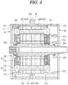
- FIGS. 1 to 4 illustrate a motor 1 that rotates by receiving power from an external power source (not illustrated).
- the motor 1 includes a housing 10, a stator 20, and a rotor 30.
- the motor 1 may include an external power source (not illustrated) and an inverter that converts external power into a three-phase power to drive the motor 1.
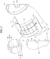
- the housing 10 will be described with reference to FIGS. 1 , 2 , and 4 .
- the housing 10 is illustrated cut in half.
- the housing 10 defines an appearance of the motor 1.
- the housing 10 is provided with a predetermined accommodation space V1 in which the stator 20 and the rotor 30 are accommodated, and a refrigerant storage space V2 in which heat-exchanged refrigerant is stored formed therein.
- the housing 10 includes a main housing 11 with both sides thereof open and first and second covers 18 and 19 covering both open sides of the main housing 11 and coupled to the main housing 11.
- the main housing 11 may be implemented in a form with only one side thereof open.
- the main housing 11 may be integrally formed with the first cover 18 or the second cover 19.
- the main housing 11 includes a main portion 12 formed in a cylindrical shape and a base portion 15 formed at a lower side of an outer circumferential surface of the main portion 12.
- the accommodation space V1 is formed by an inner circumferential surface of the main portion 12 and the first and second covers 18 and 19 covering both sides of the main housing 11.
- the base portion 15 may be formed in a shape of a square column with an open front side surface, an open rear side surface, and an open upper side surface.
- the open upper side of the base portion 15 is coupled to the outer circumferential surface of the main portion 12.
- the refrigerant storage space V2 is formed by the outer circumferential surface of the main portion 12 and the first and second covers 18 and 19 covering both sides of the base portion 15.
- An upper side of the outer circumferential surface of the main portion 12 is provided with a refrigerant supply portion 13 protruding from the housing 10.
- the refrigerant supply portion 13 is provided with a refrigerant supply hole 13a communicating the accommodation space V1 and an outside of the housing 10 formed therethrough.
- the refrigerant supply portion 13 is connected to a refrigerant circulation portion (not illustrated) that supplies refrigerant into an interior of the housing 10, and refrigerant is introduced into the housing 10 through the refrigerant supply hole 13a.
- Through holes 12a may be formed at a portion of the main portion 12 where the main portion 12 faces the base portion 15. Accordingly, refrigerant introduced into the main portion 12 to cool the stator 20 and the rotor 30 may be introduced into the refrigerant storage space V2 through the through holes 12a.
- One side surface of the base portion 15 is provided with a refrigerant discharge portion 16 protruding therefrom, and the refrigerant discharge portion 16 is provided with a refrigerant discharge hole 16a formed therethrough to communicate the refrigerant storage space V2 and outside of the base portion 15. Accordingly, the refrigerant introduced into the refrigerant storage space V2 may be discharged through the refrigerant discharge hole 16a.
- the refrigerant discharge portion 16 may be connected to a refrigerant circulation portion (not illustrated).
- the refrigerant cooled in a process of circulating the refrigerant circulation portion (not illustrated) is introduced back into the accommodation space V1 through the refrigerant supply portion 13.
- a stator core 21 to be described later is coupled to the inner circumferential surface of the main portion 12.
- the stator core 21 may be press-fitted to the inner circumferential surface of the main portion 12.
- the accommodation space V1 includes a first accommodation space V11 located at a front side of the stator core 21 and a second accommodation space V12 located at a rear side of the stator core 21.
- Through hole 12a to communicate the accommodation space V1 and the refrigerant storage space V2 is provided in plural, and the plurality of through holes 12a may be formed at a position corresponding to the first accommodation space V11 and a position corresponding to the second accommodation space V12.
- a bridge portion 14 is formed between a through hole 12a formed at the position corresponding to the first accommodation space V11 and a through hole 12a formed at the position corresponding to the second accommodation space V12.
- the bridge portion 14 forms a part of a main groove 124.
- the main groove 124 may surround the stator core 21 in a circumferential direction of the stator core 21 without being cut in a middle.
- Refrigerant flowing through the main groove 124 is discharged into the first accommodation space V11 and the second accommodation space V12 through branched grooves 125 and 126 to cool the stator 20 and the rotor 30, then is introduced into the refrigerant storage space V2 through the through holes 12a.
- the refrigerant supply portion 13 is formed at a position overlapping the stator core 21 in a radial direction, and a refrigerant supply flow path RF to supply the refrigerant introduced through the refrigerant supply hole 13a into the first accommodation space V11 and the second accommodation space V12 is formed between the inner circumferential surface of the main portion 12 and an outer circumferential surface of the stator core 21.
- the refrigerant supply flow path RF includes a main flow path MF and branched flow paths BF.
- the main flow path MF extends in the circumferential direction of the stator core 21 and communicates with the refrigerant supply hole 13a.
- refrigerant introduced into the refrigerant supply hole 13a moves in the circumferential direction through the main flow path MF between the stator core 21 and the inner circumferential surface of the main portion 12.
- the branched flow paths BF extend in an axial direction from both sides of the main flow path MF.
- the branched flow paths BF are formed to extend from both sides of the main flow path MF to the front side and the rear side, respectively, and the branched flow paths BF may be formed in plural in the circumferential direction of the stator core 21.
- the plurality of branched flow paths BF is disposed to be spaced apart from each other by a predetermined distance in the circumferential direction.
- branched flow paths BF communicate with the main flow path MF.
- refrigerant flowing through the main flow path MF is introduced into the branched flow paths BF, moved to the first accommodation space V11 and the second accommodation space V12 through the branched flow path BF, and then be discharged.
- the inner circumferential surface of the main portion 12 facing the outer circumferential surface of the stator core 21 is provided with a refrigerant supply groove 123 forming a refrigerant supply flow path RF recessed therein.
- the refrigerant supply flow path RF is formed in a space between the refrigerant supply groove 123 and the outer circumferential surface of the stator core 21 facing the refrigerant supply groove 123.
- the refrigerant supply groove 123 includes the main groove 124 and the branched grooves 125 and 126.
- the main groove 124 extends in the circumferential direction of the stator core 21 and is connected to the refrigerant supply hole 13a.
- the main flow path MF is formed in a space between the main groove 124 and the outer circumferential surface of the stator core 21 facing the main groove 124.
- the branched grooves 125 and 126 include a first branched groove 125 and a second branched groove 126.
- the first branched groove 125 is connected to a front side of the main groove 124 and extends to a front side in the axial direction.
- the second branched groove 126 is connected to a rear side of the main groove 124 and extends to a rear side in the axial direction.
- the branched flow paths BF are formed in a space between the first and second branched grooves 125 and 126 and the outer circumferential surface of the stator core 21 facing the first and second branched grooves 125 and 126.
- the main groove 124 has a predetermined width W1 in the axial direction.
- the first and second branched grooves 125 and 126 have a predetermined length D1 in the axial direction.
- a value W1+D1+D1 obtained by adding a value W1 of an axial width of the main groove 124 to a sum D1+D1 of the axial lengths of the first and second branched grooves 125 and 126 is greater than a value of the axial length of the stator core 21.
- An end portion of the first branched groove 125 faces the first accommodation space V11 rather than the outer circumferential surface of the stator core 21, and an end portion of the second branched groove 126 faces the second accommodation space V12 rather than the outer circumferential surface of the stator core 21.
- refrigerant transferred through the branched flow paths BF can be transferred from each of the end portions of the first branched groove 125 and the second branched groove 126, then be discharged to the first accommodation space V11 and the second accommodation space V12, respectively.
- a first coupling groove 121 and a second coupling groove 122 are formed at both sides of the inner circumferential surface of the main portion 12 into which the stator core 21 is press-fitted.
- the first coupling groove 121 is formed to be recessed at a front side of the main portion 12, and the second coupling groove 122 is formed to be recessed at a rear side of the main portion 12.
- the first coupling groove 121 is formed at the front side of the main portion 12 in the circumferential direction with a predetermined length in the axial direction.
- the second coupling groove 122 is formed at the rear side of the main portion 12 in the circumferential direction with a predetermined length in the axial direction.
- the predetermined lengths may be lengths respectively corresponding to a first protrusion coupling portion 181 of the first cover 18 and a second protrusion coupling portion 191 of the second cover 19 to be described later.
- Portions where the first and second coupling grooves 121 and 122 are formed in the main portion 12 have a radial thickness thinner than other portions.
- the first cover 18 and the second cover 19 are formed to cover both open sides of the main housing 11.
- the first cover 18 and the second cover 19 are formed in a shape in which a square is coupled to a lower side of a circle.
- first cover 18 and the second cover 19 may be formed in various shapes having a size capable of covering both open sides of the main housing 11.
- the first protruding coupling portion 181 is formed to protrude by a predetermined length from a rear side surface of the first cover 18.
- the predetermined length is equal to an axial length of the first coupling groove 121.
- the first protruding coupling portion 181 is formed in a shape to be engaged with the first coupling groove 121 of the main portion 12. Accordingly, when the first protruding coupling portion 181 is inserted into the open front side of the main portion 12, an outer circumferential surface of the first protruding coupling portion 181 and the first coupling groove 121 are engaged with each other. Accordingly, the first cover 18 and the front side of the main housing 11 can be coupled to each other.
- the second protruding coupling portion 191 is formed to protrude by a predetermined length from a front side surface of the second cover 19.
- the predetermined length is equal to an axial length of the second coupling groove 122.
- the second protruding coupling portion 191 is formed in a shape to be engaged with the second coupling groove 122 of the main portion 12. Accordingly, when the second protruding coupling portion 191 is inserted into the open rear side of the main portion 12, an outer circumferential surface of the second protruding coupling portion 191 and the second coupling groove 122 are engaged with each other. Accordingly, the second cover 19 and the rear side of the main housing 11 can be coupled to each other.
- first cover 18 and a front end of the main housing 11 may have a sealing portion (not illustrated) at a portion where the first cover 18 and the front end of the main housing 11 are brought into contact with each other.
- second cover 19 and a rear end of the main housing 11 may have a sealing portion (not illustrated) at a portion where the second cover 19 and the rear end of the main housing 11 are brought into contact with each other. Accordingly, leakage of refrigerant through a portion where the first cover 18 and the main housing 11 are coupled to each other and a portion where the second cover 19 and the main housing 11 are coupled to each other can be suppressed.
- a first shaft bearing portion 182 and a first shaft bearing hole 182a are formed in the first cover 18, and a second shaft bearing portion 192 and a second shaft bearing hole 192a are formed in the second cover 19.
- a front side of a shaft 32 to be described later is accommodated in the first shaft bearing hole 182a, and a rear side of the shaft 32 is accommodated in the second shaft bearing hole 192a.
- stator core 21 is coupled to the inner circumferential surface of the main portion 12, and the stator coils 22 are wound around the stator core 21.
- stator core 21 and the stator coils 22 constitute the stator 20.
- stator 20 and the rotor 30 will be described with reference to FIGS. 3 and 4 .
- a magnetic field to rotate the rotor 30 to be described later is formed in the stator 20.
- the stator 20 includes the stator core 21 and the stator coils 22 wound around the stator core 21.
- the stator core 21 includes a yoke portion 211 formed in an annular shape and a plurality of teeth portions 212 protruding radially inward from an inner circumferential surface of the yoke portion 211.
- the stator core 21 is formed to extend by a predetermined length in the axial direction.
- stator core 21 may be formed by stacking a plurality of electrical sheets having a predetermined thickness in the axial direction in an insulated manner. Accordingly, an occurrence of iron loss when the motor 1 is operated can be suppressed.
- the teeth portions 212 are disposed to be spaced apart from each other in the circumferential direction inside the yoke portion 211, and a slot 213 which is a predetermined space is formed between the teeth portions 212 adjacent to each other in the circumferential direction.
- the slot 213 is formed in plural, and the plurality of teeth portions 212 and the plurality of slots 213 are alternately disposed in the circumferential direction.
- the stator coils 22 may be wound around the plurality of teeth portions 212 and the plurality of slots 213 in a predetermined pattern.
- the stator coil 22 includes a conductor and an insulated coating surrounding the conductor.
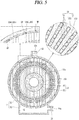
- a conductor segment or a hairpin magnet wire (hereinafter referred to as "hairpin") formed by bending a flat-angled copper wire (refer to FIG. 5 ) with a relatively large cross-sectional area into an approximately "U" shape is used.
- the stator coils 22 are electrically connected by inserting the stator coils 22 into the plurality of slots 213 in a predetermined pattern in one direction, and then welding ends of the stator coils 22 protruding toward one side of the stator core 21 in a predetermined pattern.
- an end turn portion at which bent portions of the stator coils 22 are positioned is formed at one side of the stator core 21, and a crown portion at which end portions of the stator coils 22 are electrically coupled is formed at another side of the stator core 21.
- a stranded wire may be used as the stator coil 22.
- the stator coils 22 pass through the plurality of slots 213 in the axial direction and are wound around the plurality of teeth portions 212 in a predetermined pattern.
- stator coils 22 are electrically connected to an inverter (not illustrated). And the inverter (not illustrated) converts power applied from an external power source into alternative current power for operating the motor 1, then supplies the alternative current power to the stator coils 22.
- stator coils 22 As a current is applied from the inverter (not illustrated) to the stator coils 22, a magnetic field is formed around the stator coils 22. That is, a rotating magnetic field to rotate the rotor 30 is formed in the stator 20.
- a rotor accommodation hole 21a is formed through a radially inner side of the plurality of teeth portions 212, and the rotor 30 is rotatably disposed in the rotor accommodation hole 21a.
- the rotor 30 is rotated by an interaction with the rotating magnetic field of the stator 20.
- the rotor 30 includes a rotor core 31 and the shaft 32.
- the rotor core 31 is formed to extend by a predetermined length in the axial direction.
- the rotor core 31 may be formed in an annular column shape with a shaft accommodation hole 31a formed therethrough in a central portion of the rotor core 31.
- the rotor core 31 may be formed by stacking a plurality of electrical sheets having a predetermined thickness in the axial direction in an insulated manner. Accordingly, an occurrence of iron loss when the motor 1 is operated can be suppressed.
- the rotor core 31 may include a permanent magnet (not illustrated).
- a rotating magnetic field of the stator 20 and a magnetic field of the permanent magnet (not illustrated) interact with each other. Accordingly, the rotor 30 can be rotated relative to the stator 20.
- the shaft 32 is inserted into the shaft accommodation hole 31a.
- the shaft accommodation hole 31a and the shaft 32 may be coupled to each other in a press-fitting manner.
- the shaft 32 protrudes in the axial direction to both sides of the rotor core 31, the front side of the shaft 32 is accommodated in the first shaft bearing hole 182a, and the rear side of the shaft 32 is accommodated in the second shaft bearing hole 192a.
- Refrigerant introduced through the refrigerant supply hole 13a is introduced into the main flow path MF, moves through the main flow path MF to be introduced into the branched flow paths BF, then be discharged into the first accommodation space V11 and the second accommodation space V12.
- Refrigerant is discharged into the first accommodation space V11 through the branched flow paths BF formed in the axial direction at a front side of the main flow path MF, and is discharged into the second accommodation space V12 through the branched flow paths BF formed in the axial direction at a rear side of the main flow path MF.
- branched flow paths BF are formed between the outer circumferential surface of the stator core 21 and the first branched groove 125 and between the outer circumferential surface and the second branched groove 126.
- Refrigerant discharged to the first accommodation space V11 through the branched flow paths BF is sprayed on a front side of the stator 20 and the rotor core 31.
- the refrigerant sprayed on the front side of the stator 20 and the rotor core 31 exchanges heat with the stator 20 and the rotor core 31. Heat energy is transferred from the stator 20 and the rotor core 31 having a relatively high temperature to the refrigerant having a relatively low temperature.
- refrigerant discharged to the second accommodation space V12 through the branched flow paths BF is sprayed on a rear side of the stator 20 and the rotor core 31.
- the refrigerant sprayed on the rear side of the stator 20 and the rotor core 31 exchanges heat with the stator 20 and the rotor core 31. Heat energy is transferred from the stator 20 and the rotor core 31 having a relatively high temperature to the refrigerant having a relatively low temperature.
- stator 20 and the rotor core 31 heated while the motor 1 is operating can be cooled.
- a portion where the stator coils 22 are bent or electrically coupled may be formed to protrude at a front end portion and a rear end portion of the stator 20.
- an end turn portion at which the stator coils 22 are bent may be formed at the front end portion and the rear end portion of the stator 20, and a crown portion at which the stator coils 22 are electrically coupled to each other may be formed at the rear end portion of the stator core 21.
- a portion where the stator coils 22 are bent and wound around the teeth portions 212 may be formed at the front end portion and the rear end portion of the stator 20.
- a portion where the stator coils 22 are bent or electrically coupled may generate relatively more heat energy than other portions. That is, a portion where the stator coils 22 are bent or electrically coupled is one of main heat sources of the motor 1.
- the refrigerant discharged into the first accommodation space V11 may be sprayed onto the stator coils 22 protruding from a front end portion of the stator core 21.
- the refrigerant discharged into the second accommodation space V12 may be sprayed onto the stator coils 22 protruding from the rear end portion of the stator core 21.
- the portion where the stator coils 22 are bent or electrically coupled which is one of the main heat sources of the motor 1 can be cooled.
- refrigerant flowing through the main flow path MF is distributed to the branched flow paths BF.
- the main flow path MF is formed between the outer circumferential surface of the stator core 21 and the main groove 124.
- the main flow path MF surrounds the stator core 21 in the circumferential direction of the stator core 21.
- the plurality of branched flow paths BF is disposed to be spaced apart from each other in the circumferential direction of the stator core 21, and each of the branched flow paths BF is electrically connected to the main flow path MF.
- refrigerant flowing through the main flow path MF may flow into each of the branched flow paths BF.
- the plurality of branched flow paths BF are arranged to be spaced apart from each other in the circumferential direction, an excessive amount of refrigerant being supplied to a specific portion of the stator 20 and the rotor core 31 thereby spraying an insufficient amount of refrigerant to another specific portion can be suppressed.
- each end portion of the stator 20 and the rotor core 31 can be evenly cooled in the circumferential direction.
- the refrigerant discharged to the first accommodation space V11 and the second accommodation space V12 through the branched flow paths BF cools the stator 20 and the rotor 30, and then is introduced into refrigerant storage space V2 through the through holes 12a.
- the refrigerant introduced into the refrigerant storage space V2 is discharged outside the motor 1 through the refrigerant discharge hole 16a, and then cooled again in the process of flowing through the refrigerant circulation portion (not illustrated) to be introduced into the main flow path MF through the refrigerant supply hole 13a.
- the main groove 124 forming the main flow path MF and the branched grooves 125 and 126 forming the branched flow paths BF are recessed in the inner circumferential surface of the housing.
- stator core 21 without separately processing the stator core 21 to form a flow path in the stator core 21 or adding a separate component for distributing refrigerant to the stator core 21, refrigerant can be smoothly supplied to both end portions of the stator core 21.
- stator core 21 When a flow path is formed in the stator core 21, a magnetic path area is reduced so that an output of the motor 1 may be adversely affected, and a size of the stator core 21 may be increased.
- a cost for producing the separate component may be added and an assembly process of the motor 1 may be complicated. That is, the cost for producing the motor 1 may be increased.
- refrigerant supply groove 123 is formed on the inner circumferential surface of the housing 10, refrigerant can be smoothly supplied to both end portions of the stator core 21 without reducing the magnetic path area of the stator core 21, increasing the size, or increasing the manufacturing cost.
- the motor 1 is miniaturized and the assembly process of the motor 1 is simplified, so that the manufacturing cost of the motor can be reduced.
- the bottleneck portion 124a may be defined as a space between bottleneck protrusions 1241 protruding from both side surfaces of the main groove 124 facing each other.
- An axial width W2 between the bottleneck protrusions 1241 is formed to be narrower than an axial width W1 of the main groove 124.
- the bottleneck protrusion 1241 protrudes in a shape of a square pillar.
- the shape is not limited thereto, and in an embodiment not illustrated, the bottleneck protrusions 1241 may be formed in various shapes.
- the bottleneck protrusions 1241 may be formed to protrude convexly toward each other from both side surfaces of the main groove 124 facing each other.
- a flow rate at which the refrigerant is discharged through the branched flow path BF can be increased by a simple structural change.
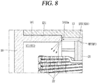
- refrigerant dispersion surfaces 181a are formed on the inner circumferential surface of the housing 10, and the refrigerant dispersion surfaces 181a are disposed at end portions of the branched grooves 125 and 126.
- the refrigerant dispersion surfaces 181a are formed in plural and are disposed at each of end portions of the plurality of branched grooves 125 and 126. That is, the plurality of refrigerant dispersion surfaces 181a is disposed to be spaced apart from each other in the circumferential direction of the stator core 21.
- Refrigerant moved through the branched flow paths BF collides with each of the refrigerant dispersion surfaces 181a and then is sprayed toward the stator coils 22 protruding from both end portions of the stator core 21.
- the refrigerant dispersion surfaces 181a are formed to be inclined in a direction crossing the axial direction. In an embodiment, the refrigerant dispersion surfaces 181a may be formed perpendicular to the axial direction.
- refrigerant colliding with the refrigerant dispersion surfaces 181a may be sprayed toward the shaft 32.
- the refrigerant dispersion surfaces 181a are formed inclined in the direction crossing the axial direction, refrigerant colliding with the refrigerant dispersion surfaces 181a can be sprayed upwardly toward the center of the shaft 32. Accordingly, the refrigerant can be sufficiently sprayed onto the stator coils 22 located at the lower side.
- stator coils 22 located at the upper side and the lower side can be cooled evenly.
- the refrigerant dispersion surfaces 181a are formed at an end portion of the first protruding coupling portion 181 and an end portion of the second protruding coupling portion 191.
- a rear end surface of the first protruding coupling portion 181 is disposed to face the end portion of the first branched groove 125.
- refrigerant moved through the first branched groove 125 collides with the rear end surface of the first protruding coupling portion 181. That is, refrigerant collides with the refrigerant dispersion surface 181a formed at the end portion of the first protruding coupling portion 181 to be sprayed toward the center of the shaft 32.
- a front end surface of the second protruding coupling portion 191 is disposed to face an end portion of the second branched groove 126.
- refrigerant moved through the second branched groove 126 collides with the front end surface of the second protruding coupling portion 191. That is, refrigerant collides with the refrigerant dispersion surface (not shown) formed at the end portion of the second protruding coupling portion 191 to be sprayed toward the center of the shaft 32.
- the first protruding coupling portion 181 and the second protruding coupling portion 191 may be formed to protrude radially inward from a portion of the housing 10 at which the refrigerant supply groove 123 is formed. That is, in a coupled state, there is a step difference between the first and second protruding coupling portions 181 and 191 and the main housing 11.
- a refrigerant dispersion surface 1810a according to the modified embodiment may be formed inclined in a direction away from the main groove 124.
- the inclined refrigerant dispersion surface 1810a may be formed by chamfering a corner forming an inner circumference of an end portion of the first protruding coupling portion 181 in the circumferential direction.
- the refrigerant dispersion surface (not shown) may be formed by chamfering a corner forming an inner circumference of an end portion of the second protruding coupling portion 191 in the circumferential direction.
- the inclined refrigerant dispersion surfaces 1810a may be disposed at the end portions of the first and second protruding coupling portions 181 and 191 facing each of the end portions of the branched grooves 125 and 126.
- Refrigerant moved through the branched grooves 125 and 126 is moved through the inclined refrigerant dispersion surfaces 1810a to be sprayed toward the center of the shaft 32.
- refrigerant can be sprayed farther from the front end portion of the stator core 21, and refrigerant can be sprayed farther from the rear end portion of the stator core 21.
- a length of the stator coils 22 protruding from each of the end portions of the stator core 21 may be changed.
- refrigerant may reach farther in the axial direction when a slope of the refrigerant dispersion surface 181a is formed more smoothly. Accordingly, refrigerant can be sprayed all over the stator coils 22.
- stator coils 22 When the protruding length of the stator coils 22 is relatively short, it is preferable to form the slop of the refrigerant dispersion surface 181a more abruptly or vertically.
- FIG. 9 another modified embodiment of the refrigerant dispersion surface 181a is illustrated.
- An end portion of the first protruding coupling portion 181 according to the another modified embodiment may be provided with refrigerant dispersion grooves 1810b each formed recessed.
- the refrigerant dispersion grooves 1810b are formed at positions corresponding to each of the end portions of the first branched grooves 125.
- the refrigerant dispersion grooves 1810b may be formed in a quarter-sphere shape each opened toward the first branched groove 125 and the shaft 32.
- refrigerant moved through the first branched groove 125 may be moved through the curved surface of the refrigerant dispersion groove 1810b to be intensively sprayed toward the center of the shaft 32.
- refrigerant can be intensively sprayed to a specific portion rather than being sprayed over a larger area.
- stator coils 22 protruding toward the front side of the stator core 21 are densely disposed at a specific portion, a cooling effect can be improved by intensively spraying refrigerant to the specific portion.
- an end portion of the second protruding coupling portion 191 according to the another modified embodiment may be provided with refrigerant dispersion grooves (not shown) each formed recessed.
- the refrigerant dispersion grooves (not shown) are formed at positions corresponding to each of the end portions of the second branched grooves 126.
- the refrigerant dispersion grooves may be formed in a quarter-sphere shape each opened toward the second branched groove 126 and the shaft 32.
- the refrigerant moved through the second branched groove 126 may be moved through the curved surface of the refrigerant dispersion groove (not shown) to be intensively sprayed toward the center of the shaft 32.
- refrigerant can be intensively sprayed to a specific portion rather than being sprayed over a larger area.
- stator coils 22 protruding toward the rear side of the stator core 21 are densely disposed at a specific portion, a cooling effect can be improved by intensively spraying the refrigerant to the specific portion.
- the refrigerant dispersion surfaces 181a and 1810a may be formed at an upper side, based on the direction in which the motor 1 is installed, and the refrigerant dispersion grooves 1810b may be formed at a lower side.
- the refrigerant dispersion grooves 1810b By forming the refrigerant dispersion grooves 1810b at the lower side, a distance in which refrigerant sprayed upwardly from the lower side may be increased.
- refrigerant can be sprayed over a wider range at the upper side, and refrigerant can smoothly reach the stator coils 22 at the lower side.
- refrigerant moved through the axial flow paths may collide with the refrigerant dispersion structure to be sprayed toward the center of the shaft 32.
- refrigerant can be sprayed toward the crown portion and the end turn of the stator coils 22 located at both end portions of the stator core 21.
Landscapes
- Engineering & Computer Science (AREA)
- Power Engineering (AREA)
- Iron Core Of Rotating Electric Machines (AREA)
- Motor Or Generator Cooling System (AREA)
Applications Claiming Priority (1)
| Application Number | Priority Date | Filing Date | Title |
|---|---|---|---|
| KR1020200040992A KR102729525B1 (ko) | 2020-04-03 | 2020-04-03 | 모터 |
Publications (2)
| Publication Number | Publication Date |
|---|---|
| EP3890164A1 true EP3890164A1 (fr) | 2021-10-06 |
| EP3890164B1 EP3890164B1 (fr) | 2024-09-04 |
Family
ID=73789862
Family Applications (1)
| Application Number | Title | Priority Date | Filing Date |
|---|---|---|---|
| EP20212653.8A Active EP3890164B1 (fr) | 2020-04-03 | 2020-12-09 | Moteur |
Country Status (4)
| Country | Link |
|---|---|
| US (1) | US11670981B2 (fr) |
| EP (1) | EP3890164B1 (fr) |
| KR (1) | KR102729525B1 (fr) |
| CN (1) | CN113497512B (fr) |
Families Citing this family (5)
| Publication number | Priority date | Publication date | Assignee | Title |
|---|---|---|---|---|
| CA3215538A1 (fr) * | 2021-05-12 | 2022-11-17 | Majed ETEMADI | Refroidissement par jet tangentiel pour moteurs electriques |
| CN114785049A (zh) * | 2022-05-11 | 2022-07-22 | 中国第一汽车股份有限公司 | 一种插针绕组式电机的冷却结构及电机 |
| US20240072603A1 (en) * | 2022-08-24 | 2024-02-29 | Honeywell International Inc. | Cooling end turns in high power density electric generators |
| US20250300526A1 (en) * | 2024-03-19 | 2025-09-25 | Honeywell International Inc. | Integrated two phase cooling sleeve |
| WO2025197060A1 (fr) * | 2024-03-22 | 2025-09-25 | 三菱電機株式会社 | Moteur électrique et dispositif de soufflage |
Citations (9)
| Publication number | Priority date | Publication date | Assignee | Title |
|---|---|---|---|---|
| US3531668A (en) * | 1969-02-10 | 1970-09-29 | Caterpillar Tractor Co | Induction motor having cooling arrangement |
| JP2003324901A (ja) * | 2002-04-26 | 2003-11-14 | Nippon Soken Inc | 電動機 |
| CN201355790Y (zh) * | 2008-12-30 | 2009-12-02 | 上海大郡自动化系统工程有限公司 | 油冷电机 |
| KR20120058336A (ko) * | 2010-11-29 | 2012-06-07 | 엘지전자 주식회사 | 전동기 |
| JP2014225969A (ja) * | 2013-05-16 | 2014-12-04 | 本田技研工業株式会社 | 電動機 |
| CN204906112U (zh) | 2015-08-25 | 2015-12-23 | 比亚迪股份有限公司 | 油冷电机及车辆 |
| US20160164377A1 (en) * | 2014-12-04 | 2016-06-09 | Atieva, Inc. | Motor Cooling System |
| JP2017093002A (ja) * | 2015-11-02 | 2017-05-25 | Ntn株式会社 | モータ駆動装置 |
| CN107276266A (zh) * | 2017-08-02 | 2017-10-20 | 华中科技大学 | 一种双向冷却油冷电机 |
Family Cites Families (6)
| Publication number | Priority date | Publication date | Assignee | Title |
|---|---|---|---|---|
| US8482173B2 (en) * | 2009-01-14 | 2013-07-09 | Regal Beloit America, Inc. | End shield and inner bearing cap assembly |
| JP5505275B2 (ja) * | 2010-11-22 | 2014-05-28 | アイシン・エィ・ダブリュ株式会社 | ステータ冷却装置 |
| JP6279059B1 (ja) * | 2016-11-25 | 2018-02-14 | 三菱電機株式会社 | 回転電機 |
| CN109756056A (zh) * | 2017-11-07 | 2019-05-14 | 华为技术有限公司 | 电机、动力总成、动力设备及电机冷却方法 |
| EP3539813A1 (fr) * | 2018-03-14 | 2019-09-18 | Kanzaki Kokyukoki Manufacturing Co. Ltd. | Réducteur |
| CN110943566B (zh) * | 2019-11-28 | 2025-05-27 | 珠海格力电器股份有限公司 | 电机以及具有其的汽车 |
-
2020
- 2020-04-03 KR KR1020200040992A patent/KR102729525B1/ko active Active
- 2020-12-09 EP EP20212653.8A patent/EP3890164B1/fr active Active
- 2020-12-28 US US17/135,276 patent/US11670981B2/en active Active
- 2020-12-30 CN CN202011609803.9A patent/CN113497512B/zh active Active
Patent Citations (9)
| Publication number | Priority date | Publication date | Assignee | Title |
|---|---|---|---|---|
| US3531668A (en) * | 1969-02-10 | 1970-09-29 | Caterpillar Tractor Co | Induction motor having cooling arrangement |
| JP2003324901A (ja) * | 2002-04-26 | 2003-11-14 | Nippon Soken Inc | 電動機 |
| CN201355790Y (zh) * | 2008-12-30 | 2009-12-02 | 上海大郡自动化系统工程有限公司 | 油冷电机 |
| KR20120058336A (ko) * | 2010-11-29 | 2012-06-07 | 엘지전자 주식회사 | 전동기 |
| JP2014225969A (ja) * | 2013-05-16 | 2014-12-04 | 本田技研工業株式会社 | 電動機 |
| US20160164377A1 (en) * | 2014-12-04 | 2016-06-09 | Atieva, Inc. | Motor Cooling System |
| CN204906112U (zh) | 2015-08-25 | 2015-12-23 | 比亚迪股份有限公司 | 油冷电机及车辆 |
| JP2017093002A (ja) * | 2015-11-02 | 2017-05-25 | Ntn株式会社 | モータ駆動装置 |
| CN107276266A (zh) * | 2017-08-02 | 2017-10-20 | 华中科技大学 | 一种双向冷却油冷电机 |
Also Published As
| Publication number | Publication date |
|---|---|
| CN113497512B (zh) | 2025-08-15 |
| US20210313858A1 (en) | 2021-10-07 |
| CN113497512A (zh) | 2021-10-12 |
| US11670981B2 (en) | 2023-06-06 |
| KR20210123620A (ko) | 2021-10-14 |
| EP3890164B1 (fr) | 2024-09-04 |
| KR102729525B1 (ko) | 2024-11-14 |
Similar Documents
| Publication | Publication Date | Title |
|---|---|---|
| EP3890164B1 (fr) | Moteur | |
| US9362809B2 (en) | Stator for electric rotary machine and fabricating method of the same | |
| JP5088577B2 (ja) | 回転電機 | |
| US7952245B2 (en) | Power distribution unit for rotary electric machine with linear conductor connecting ring having terminal section with axially extending hole for connecting stator coil, and method for assembling rotary electric machine | |
| US6137201A (en) | AC generator for vehicles | |
| EP2273654B1 (fr) | Machine électrique tournante et son procédé de fabrication | |
| EP1124305B1 (fr) | Extrémités de bobinages statoriques pour un alternateur de véhicule | |
| EP1551091B1 (fr) | Stator destine a un generateur multipolaire de rotor externe et procede d'assemblage du stator | |
| US11722029B2 (en) | Rotary electric machine | |
| US20090218906A1 (en) | Rotating electric machine and method of manufacturing the same | |
| CN114128086A (zh) | 分裂铁芯组装体以及包括其的定子 | |
| WO2013154054A1 (fr) | Moteur sans balais | |
| US20260031676A1 (en) | Axial flux motor and vehicle | |
| JP7258201B2 (ja) | 3相コネクタ一体型ステータ及びこれを含む電動圧縮機 | |
| EP2031735B1 (fr) | Stator et moteur électrique | |
| EP0881742B1 (fr) | Générateur à courant alternatif pour véhicules | |
| KR20010077851A (ko) | 교류 발전기 | |
| JP5854268B2 (ja) | 回転電機の固定子 | |
| JP5330860B2 (ja) | 回転電機 | |
| CN117713429A (zh) | 一种电机冷却结构 | |
| CN115244835A (zh) | 用于机动车辆的电动马达式的驱动器 | |
| US20250192645A1 (en) | Electric drive system and vehicle | |
| US12431755B2 (en) | Insulation system and method of insulating | |
| KR20220053343A (ko) | 모터 조립체 | |
| US20250279687A1 (en) | Electric motor and components |
Legal Events
| Date | Code | Title | Description |
|---|---|---|---|
| PUAI | Public reference made under article 153(3) epc to a published international application that has entered the european phase |
Free format text: ORIGINAL CODE: 0009012 |
|
| STAA | Information on the status of an ep patent application or granted ep patent |
Free format text: STATUS: REQUEST FOR EXAMINATION WAS MADE |
|
| 17P | Request for examination filed |
Effective date: 20210811 |
|
| AK | Designated contracting states |
Kind code of ref document: A1 Designated state(s): AL AT BE BG CH CY CZ DE DK EE ES FI FR GB GR HR HU IE IS IT LI LT LU LV MC MK MT NL NO PL PT RO RS SE SI SK SM TR |
|
| RAP1 | Party data changed (applicant data changed or rights of an application transferred) |
Owner name: LG MAGNA E-POWERTRAIN CO., LTD. |
|
| GRAP | Despatch of communication of intention to grant a patent |
Free format text: ORIGINAL CODE: EPIDOSNIGR1 |
|
| STAA | Information on the status of an ep patent application or granted ep patent |
Free format text: STATUS: GRANT OF PATENT IS INTENDED |
|
| INTG | Intention to grant announced |
Effective date: 20240423 |
|
| GRAS | Grant fee paid |
Free format text: ORIGINAL CODE: EPIDOSNIGR3 |
|
| GRAA | (expected) grant |
Free format text: ORIGINAL CODE: 0009210 |
|
| STAA | Information on the status of an ep patent application or granted ep patent |
Free format text: STATUS: THE PATENT HAS BEEN GRANTED |
|
| AK | Designated contracting states |
Kind code of ref document: B1 Designated state(s): AL AT BE BG CH CY CZ DE DK EE ES FI FR GB GR HR HU IE IS IT LI LT LU LV MC MK MT NL NO PL PT RO RS SE SI SK SM TR |
|
| REG | Reference to a national code |
Ref country code: GB Ref legal event code: FG4D |
|
| REG | Reference to a national code |
Ref country code: CH Ref legal event code: EP |
|
| REG | Reference to a national code |
Ref country code: IE Ref legal event code: FG4D |
|
| REG | Reference to a national code |
Ref country code: DE Ref legal event code: R096 Ref document number: 602020036996 Country of ref document: DE |
|
| REG | Reference to a national code |
Ref country code: LT Ref legal event code: MG9D |
|
| REG | Reference to a national code |
Ref country code: NL Ref legal event code: MP Effective date: 20240904 |
|
| PG25 | Lapsed in a contracting state [announced via postgrant information from national office to epo] |
Ref country code: NO Free format text: LAPSE BECAUSE OF FAILURE TO SUBMIT A TRANSLATION OF THE DESCRIPTION OR TO PAY THE FEE WITHIN THE PRESCRIBED TIME-LIMIT Effective date: 20241204 |
|
| PG25 | Lapsed in a contracting state [announced via postgrant information from national office to epo] |
Ref country code: GR Free format text: LAPSE BECAUSE OF FAILURE TO SUBMIT A TRANSLATION OF THE DESCRIPTION OR TO PAY THE FEE WITHIN THE PRESCRIBED TIME-LIMIT Effective date: 20241205 Ref country code: PL Free format text: LAPSE BECAUSE OF FAILURE TO SUBMIT A TRANSLATION OF THE DESCRIPTION OR TO PAY THE FEE WITHIN THE PRESCRIBED TIME-LIMIT Effective date: 20240904 Ref country code: FI Free format text: LAPSE BECAUSE OF FAILURE TO SUBMIT A TRANSLATION OF THE DESCRIPTION OR TO PAY THE FEE WITHIN THE PRESCRIBED TIME-LIMIT Effective date: 20240904 |
|
| PG25 | Lapsed in a contracting state [announced via postgrant information from national office to epo] |
Ref country code: BG Free format text: LAPSE BECAUSE OF FAILURE TO SUBMIT A TRANSLATION OF THE DESCRIPTION OR TO PAY THE FEE WITHIN THE PRESCRIBED TIME-LIMIT Effective date: 20240904 |
|
| PG25 | Lapsed in a contracting state [announced via postgrant information from national office to epo] |
Ref country code: LV Free format text: LAPSE BECAUSE OF FAILURE TO SUBMIT A TRANSLATION OF THE DESCRIPTION OR TO PAY THE FEE WITHIN THE PRESCRIBED TIME-LIMIT Effective date: 20240904 |
|
| PG25 | Lapsed in a contracting state [announced via postgrant information from national office to epo] |
Ref country code: HR Free format text: LAPSE BECAUSE OF FAILURE TO SUBMIT A TRANSLATION OF THE DESCRIPTION OR TO PAY THE FEE WITHIN THE PRESCRIBED TIME-LIMIT Effective date: 20240904 |
|
| PG25 | Lapsed in a contracting state [announced via postgrant information from national office to epo] |
Ref country code: ES Free format text: LAPSE BECAUSE OF FAILURE TO SUBMIT A TRANSLATION OF THE DESCRIPTION OR TO PAY THE FEE WITHIN THE PRESCRIBED TIME-LIMIT Effective date: 20240904 Ref country code: RS Free format text: LAPSE BECAUSE OF FAILURE TO SUBMIT A TRANSLATION OF THE DESCRIPTION OR TO PAY THE FEE WITHIN THE PRESCRIBED TIME-LIMIT Effective date: 20241204 |
|
| PG25 | Lapsed in a contracting state [announced via postgrant information from national office to epo] |
Ref country code: RS Free format text: LAPSE BECAUSE OF FAILURE TO SUBMIT A TRANSLATION OF THE DESCRIPTION OR TO PAY THE FEE WITHIN THE PRESCRIBED TIME-LIMIT Effective date: 20241204 Ref country code: PL Free format text: LAPSE BECAUSE OF FAILURE TO SUBMIT A TRANSLATION OF THE DESCRIPTION OR TO PAY THE FEE WITHIN THE PRESCRIBED TIME-LIMIT Effective date: 20240904 Ref country code: NO Free format text: LAPSE BECAUSE OF FAILURE TO SUBMIT A TRANSLATION OF THE DESCRIPTION OR TO PAY THE FEE WITHIN THE PRESCRIBED TIME-LIMIT Effective date: 20241204 Ref country code: LV Free format text: LAPSE BECAUSE OF FAILURE TO SUBMIT A TRANSLATION OF THE DESCRIPTION OR TO PAY THE FEE WITHIN THE PRESCRIBED TIME-LIMIT Effective date: 20240904 Ref country code: HR Free format text: LAPSE BECAUSE OF FAILURE TO SUBMIT A TRANSLATION OF THE DESCRIPTION OR TO PAY THE FEE WITHIN THE PRESCRIBED TIME-LIMIT Effective date: 20240904 Ref country code: GR Free format text: LAPSE BECAUSE OF FAILURE TO SUBMIT A TRANSLATION OF THE DESCRIPTION OR TO PAY THE FEE WITHIN THE PRESCRIBED TIME-LIMIT Effective date: 20241205 Ref country code: FI Free format text: LAPSE BECAUSE OF FAILURE TO SUBMIT A TRANSLATION OF THE DESCRIPTION OR TO PAY THE FEE WITHIN THE PRESCRIBED TIME-LIMIT Effective date: 20240904 Ref country code: ES Free format text: LAPSE BECAUSE OF FAILURE TO SUBMIT A TRANSLATION OF THE DESCRIPTION OR TO PAY THE FEE WITHIN THE PRESCRIBED TIME-LIMIT Effective date: 20240904 Ref country code: BG Free format text: LAPSE BECAUSE OF FAILURE TO SUBMIT A TRANSLATION OF THE DESCRIPTION OR TO PAY THE FEE WITHIN THE PRESCRIBED TIME-LIMIT Effective date: 20240904 |
|
| REG | Reference to a national code |
Ref country code: AT Ref legal event code: MK05 Ref document number: 1721440 Country of ref document: AT Kind code of ref document: T Effective date: 20240904 |
|
| PG25 | Lapsed in a contracting state [announced via postgrant information from national office to epo] |
Ref country code: NL Free format text: LAPSE BECAUSE OF FAILURE TO SUBMIT A TRANSLATION OF THE DESCRIPTION OR TO PAY THE FEE WITHIN THE PRESCRIBED TIME-LIMIT Effective date: 20240904 |
|
| PG25 | Lapsed in a contracting state [announced via postgrant information from national office to epo] |
Ref country code: IS Free format text: LAPSE BECAUSE OF FAILURE TO SUBMIT A TRANSLATION OF THE DESCRIPTION OR TO PAY THE FEE WITHIN THE PRESCRIBED TIME-LIMIT Effective date: 20250104 Ref country code: PT Free format text: LAPSE BECAUSE OF FAILURE TO SUBMIT A TRANSLATION OF THE DESCRIPTION OR TO PAY THE FEE WITHIN THE PRESCRIBED TIME-LIMIT Effective date: 20250106 |
|
| PG25 | Lapsed in a contracting state [announced via postgrant information from national office to epo] |
Ref country code: SM Free format text: LAPSE BECAUSE OF FAILURE TO SUBMIT A TRANSLATION OF THE DESCRIPTION OR TO PAY THE FEE WITHIN THE PRESCRIBED TIME-LIMIT Effective date: 20240904 Ref country code: RO Free format text: LAPSE BECAUSE OF FAILURE TO SUBMIT A TRANSLATION OF THE DESCRIPTION OR TO PAY THE FEE WITHIN THE PRESCRIBED TIME-LIMIT Effective date: 20240904 |
|
| PG25 | Lapsed in a contracting state [announced via postgrant information from national office to epo] |
Ref country code: EE Free format text: LAPSE BECAUSE OF FAILURE TO SUBMIT A TRANSLATION OF THE DESCRIPTION OR TO PAY THE FEE WITHIN THE PRESCRIBED TIME-LIMIT Effective date: 20240904 Ref country code: AT Free format text: LAPSE BECAUSE OF FAILURE TO SUBMIT A TRANSLATION OF THE DESCRIPTION OR TO PAY THE FEE WITHIN THE PRESCRIBED TIME-LIMIT Effective date: 20240904 |
|
| PG25 | Lapsed in a contracting state [announced via postgrant information from national office to epo] |
Ref country code: CZ Free format text: LAPSE BECAUSE OF FAILURE TO SUBMIT A TRANSLATION OF THE DESCRIPTION OR TO PAY THE FEE WITHIN THE PRESCRIBED TIME-LIMIT Effective date: 20240904 |
|
| PG25 | Lapsed in a contracting state [announced via postgrant information from national office to epo] |
Ref country code: IT Free format text: LAPSE BECAUSE OF FAILURE TO SUBMIT A TRANSLATION OF THE DESCRIPTION OR TO PAY THE FEE WITHIN THE PRESCRIBED TIME-LIMIT Effective date: 20240904 Ref country code: SK Free format text: LAPSE BECAUSE OF FAILURE TO SUBMIT A TRANSLATION OF THE DESCRIPTION OR TO PAY THE FEE WITHIN THE PRESCRIBED TIME-LIMIT Effective date: 20240904 |
|
| REG | Reference to a national code |
Ref country code: DE Ref legal event code: R097 Ref document number: 602020036996 Country of ref document: DE |
|
| PG25 | Lapsed in a contracting state [announced via postgrant information from national office to epo] |
Ref country code: MC Free format text: LAPSE BECAUSE OF FAILURE TO SUBMIT A TRANSLATION OF THE DESCRIPTION OR TO PAY THE FEE WITHIN THE PRESCRIBED TIME-LIMIT Effective date: 20240904 |
|
| PG25 | Lapsed in a contracting state [announced via postgrant information from national office to epo] |
Ref country code: DK Free format text: LAPSE BECAUSE OF FAILURE TO SUBMIT A TRANSLATION OF THE DESCRIPTION OR TO PAY THE FEE WITHIN THE PRESCRIBED TIME-LIMIT Effective date: 20240904 |
|
| PLBE | No opposition filed within time limit |
Free format text: ORIGINAL CODE: 0009261 |
|
| STAA | Information on the status of an ep patent application or granted ep patent |
Free format text: STATUS: NO OPPOSITION FILED WITHIN TIME LIMIT |
|
| REG | Reference to a national code |
Ref country code: CH Ref legal event code: PL |
|
| 26N | No opposition filed |
Effective date: 20250605 |
|
| PG25 | Lapsed in a contracting state [announced via postgrant information from national office to epo] |
Ref country code: LU Free format text: LAPSE BECAUSE OF NON-PAYMENT OF DUE FEES Effective date: 20241209 |
|
| GBPC | Gb: european patent ceased through non-payment of renewal fee |
Effective date: 20241209 |
|
| PG25 | Lapsed in a contracting state [announced via postgrant information from national office to epo] |
Ref country code: SE Free format text: LAPSE BECAUSE OF FAILURE TO SUBMIT A TRANSLATION OF THE DESCRIPTION OR TO PAY THE FEE WITHIN THE PRESCRIBED TIME-LIMIT Effective date: 20240904 |
|
| REG | Reference to a national code |
Ref country code: BE Ref legal event code: MM Effective date: 20241231 |
|
| PG25 | Lapsed in a contracting state [announced via postgrant information from national office to epo] |
Ref country code: GB Free format text: LAPSE BECAUSE OF NON-PAYMENT OF DUE FEES Effective date: 20241209 Ref country code: BE Free format text: LAPSE BECAUSE OF NON-PAYMENT OF DUE FEES Effective date: 20241231 |
|
| PG25 | Lapsed in a contracting state [announced via postgrant information from national office to epo] |
Ref country code: FR Free format text: LAPSE BECAUSE OF NON-PAYMENT OF DUE FEES Effective date: 20241231 |
|
| PG25 | Lapsed in a contracting state [announced via postgrant information from national office to epo] |
Ref country code: CH Free format text: LAPSE BECAUSE OF NON-PAYMENT OF DUE FEES Effective date: 20241231 |
|
| PG25 | Lapsed in a contracting state [announced via postgrant information from national office to epo] |
Ref country code: IE Free format text: LAPSE BECAUSE OF NON-PAYMENT OF DUE FEES Effective date: 20241209 |
|
| PGFP | Annual fee paid to national office [announced via postgrant information from national office to epo] |
Ref country code: DE Payment date: 20251105 Year of fee payment: 6 |