EP3890196B1 - Vorrichtung und methode zur kommunikation und drahtlosem laden - Google Patents
Vorrichtung und methode zur kommunikation und drahtlosem laden Download PDFInfo
- Publication number
- EP3890196B1 EP3890196B1 EP20167897.6A EP20167897A EP3890196B1 EP 3890196 B1 EP3890196 B1 EP 3890196B1 EP 20167897 A EP20167897 A EP 20167897A EP 3890196 B1 EP3890196 B1 EP 3890196B1
- Authority
- EP
- European Patent Office
- Prior art keywords
- antenna
- nfc
- controller
- communication device
- wireless charging
- Prior art date
- Legal status (The legal status is an assumption and is not a legal conclusion. Google has not performed a legal analysis and makes no representation as to the accuracy of the status listed.)
- Active
Links
Images





Classifications
-
- H—ELECTRICITY
- H04—ELECTRIC COMMUNICATION TECHNIQUE
- H04B—TRANSMISSION
- H04B5/00—Near-field transmission systems, e.g. inductive or capacitive transmission systems
- H04B5/70—Near-field transmission systems, e.g. inductive or capacitive transmission systems specially adapted for specific purposes
- H04B5/79—Near-field transmission systems, e.g. inductive or capacitive transmission systems specially adapted for specific purposes for data transfer in combination with power transfer
-
- H—ELECTRICITY
- H02—GENERATION; CONVERSION OR DISTRIBUTION OF ELECTRIC POWER
- H02J—ELECTRIC POWER NETWORKS; CIRCUIT ARRANGEMENTS OR SYSTEMS FOR SUPPLYING OR DISTRIBUTING ELECTRIC POWER; SYSTEMS FOR STORING ELECTRIC ENERGY
- H02J50/00—Circuit arrangements or systems for wireless supply or distribution of electric power
- H02J50/10—Circuit arrangements or systems for wireless supply or distribution of electric power using inductive coupling
-
- H—ELECTRICITY
- H02—GENERATION; CONVERSION OR DISTRIBUTION OF ELECTRIC POWER
- H02J—ELECTRIC POWER NETWORKS; CIRCUIT ARRANGEMENTS OR SYSTEMS FOR SUPPLYING OR DISTRIBUTING ELECTRIC POWER; SYSTEMS FOR STORING ELECTRIC ENERGY
- H02J50/00—Circuit arrangements or systems for wireless supply or distribution of electric power
- H02J50/20—Circuit arrangements or systems for wireless supply or distribution of electric power using microwaves or radio frequency waves
-
- H—ELECTRICITY
- H02—GENERATION; CONVERSION OR DISTRIBUTION OF ELECTRIC POWER
- H02J—ELECTRIC POWER NETWORKS; CIRCUIT ARRANGEMENTS OR SYSTEMS FOR SUPPLYING OR DISTRIBUTING ELECTRIC POWER; SYSTEMS FOR STORING ELECTRIC ENERGY
- H02J50/00—Circuit arrangements or systems for wireless supply or distribution of electric power
- H02J50/80—Circuit arrangements or systems for wireless supply or distribution of electric power involving the exchange of data, concerning supply or distribution of electric power, between transmitting devices and receiving devices
-
- H—ELECTRICITY
- H02—GENERATION; CONVERSION OR DISTRIBUTION OF ELECTRIC POWER
- H02J—ELECTRIC POWER NETWORKS; CIRCUIT ARRANGEMENTS OR SYSTEMS FOR SUPPLYING OR DISTRIBUTING ELECTRIC POWER; SYSTEMS FOR STORING ELECTRIC ENERGY
- H02J50/00—Circuit arrangements or systems for wireless supply or distribution of electric power
- H02J50/90—Circuit arrangements or systems for wireless supply or distribution of electric power involving detection or optimisation of position, e.g. alignment
-
- H—ELECTRICITY
- H02—GENERATION; CONVERSION OR DISTRIBUTION OF ELECTRIC POWER
- H02J—ELECTRIC POWER NETWORKS; CIRCUIT ARRANGEMENTS OR SYSTEMS FOR SUPPLYING OR DISTRIBUTING ELECTRIC POWER; SYSTEMS FOR STORING ELECTRIC ENERGY
- H02J7/00—Circuit arrangements for charging or discharging batteries or for supplying loads from batteries
- H02J7/40—Circuit arrangements for charging or discharging batteries or for supplying loads from batteries characterised by the exchange of charge or discharge related data
- H02J7/42—Circuit arrangements for charging or discharging batteries or for supplying loads from batteries characterised by the exchange of charge or discharge related data with electronic devices having internal batteries, e.g. mobile phones
-
- H—ELECTRICITY
- H04—ELECTRIC COMMUNICATION TECHNIQUE
- H04B—TRANSMISSION
- H04B5/00—Near-field transmission systems, e.g. inductive or capacitive transmission systems
- H04B5/20—Near-field transmission systems, e.g. inductive or capacitive transmission systems characterised by the transmission technique; characterised by the transmission medium
-
- H—ELECTRICITY
- H04—ELECTRIC COMMUNICATION TECHNIQUE
- H04B—TRANSMISSION
- H04B5/00—Near-field transmission systems, e.g. inductive or capacitive transmission systems
- H04B5/20—Near-field transmission systems, e.g. inductive or capacitive transmission systems characterised by the transmission technique; characterised by the transmission medium
- H04B5/24—Inductive coupling
- H04B5/26—Inductive coupling using coils
- H04B5/263—Multiple coils at either side
-
- H—ELECTRICITY
- H04—ELECTRIC COMMUNICATION TECHNIQUE
- H04B—TRANSMISSION
- H04B5/00—Near-field transmission systems, e.g. inductive or capacitive transmission systems
- H04B5/40—Near-field transmission systems, e.g. inductive or capacitive transmission systems characterised by components specially adapted for near-field transmission
- H04B5/43—Antennas
-
- H—ELECTRICITY
- H04—ELECTRIC COMMUNICATION TECHNIQUE
- H04B—TRANSMISSION
- H04B5/00—Near-field transmission systems, e.g. inductive or capacitive transmission systems
- H04B5/70—Near-field transmission systems, e.g. inductive or capacitive transmission systems specially adapted for specific purposes
- H04B5/77—Near-field transmission systems, e.g. inductive or capacitive transmission systems specially adapted for specific purposes for interrogation
-
- H—ELECTRICITY
- H04—ELECTRIC COMMUNICATION TECHNIQUE
- H04B—TRANSMISSION
- H04B7/00—Radio transmission systems, i.e. using radiation field
- H04B7/02—Diversity systems; Multi-antenna system, i.e. transmission or reception using multiple antennas
- H04B7/04—Diversity systems; Multi-antenna system, i.e. transmission or reception using multiple antennas using two or more spaced independent antennas
- H04B7/06—Diversity systems; Multi-antenna system, i.e. transmission or reception using multiple antennas using two or more spaced independent antennas at the transmitting station
- H04B7/0602—Diversity systems; Multi-antenna system, i.e. transmission or reception using multiple antennas using two or more spaced independent antennas at the transmitting station using antenna switching
-
- H—ELECTRICITY
- H04—ELECTRIC COMMUNICATION TECHNIQUE
- H04B—TRANSMISSION
- H04B7/00—Radio transmission systems, i.e. using radiation field
- H04B7/02—Diversity systems; Multi-antenna system, i.e. transmission or reception using multiple antennas
- H04B7/04—Diversity systems; Multi-antenna system, i.e. transmission or reception using multiple antennas using two or more spaced independent antennas
- H04B7/08—Diversity systems; Multi-antenna system, i.e. transmission or reception using multiple antennas using two or more spaced independent antennas at the receiving station
- H04B7/0802—Diversity systems; Multi-antenna system, i.e. transmission or reception using multiple antennas using two or more spaced independent antennas at the receiving station using antenna selection
-
- H—ELECTRICITY
- H04—ELECTRIC COMMUNICATION TECHNIQUE
- H04B—TRANSMISSION
- H04B5/00—Near-field transmission systems, e.g. inductive or capacitive transmission systems
- H04B5/40—Near-field transmission systems, e.g. inductive or capacitive transmission systems characterised by components specially adapted for near-field transmission
- H04B5/45—Transponders
Definitions
- the present disclosure relates to a communication device. Furthermore, the present disclosure relates to a corresponding method of operating a communication device.
- NFC Near field communication
- a primary device may generate a radio frequency (RF) field at a frequency of 13.56 MHz to power a secondary device. Modulation techniques are used to communicate in both directions.
- the secondary device may be a passive device (e.g. a tag or a transponder) or an active, typically battery-powered device.
- An RF field generated by an NFC reader can be used to charge the battery of the secondary device. This process is referred to as wireless charging.
- the NFC communication channel may be used to control the charging operation.
- US 2016/365743 A1 describes a near field communication wireless charging apparatus includes an antenna, an antenna switching unit, a control unit, a near field communication unit and a charging unit.
- the wireless charging apparatus is configured to operate in a wireless communication mode and in a wireless charging mode.
- US 2017/098149 A1 describes wireless power transmitters configured to detect a radio frequency identification (RFID) tag.
- RFID radio frequency identification
- a controller is configured to control a transmitter resonator, an amplifier, and an impedance matching network to cycle the transmitter between a power transmission mode and a RFID tag detection mode.
- US 2016/190856 A1 describes a battery pack which includes an antenna attached to a battery cell, a sensor configured to sense an energy level induced in the antenna, a controller configured to determine, according to a sensed signal of the sensor, whether the energy level is a first energy level for wireless charging or is a second energy level for near field communication, and a switch connecting the antenna to a battery charger or a near field communication circuit according to a control signal of the controller.
- a communication device is provided, as defined in claim 1.
- the controller is configured to detect whether the external communication device is within communication range of the first antenna by detecting the presence of a radio frequency (RF) field.
- RF radio frequency
- the controller is configured to conclude that the external communication device is within communication range of the first antenna if the strength of said RF field exceeds a predefined threshold.
- the controller is configured to detect whether the external communication device is within communication range of the first antenna by detecting a load change on the first antenna.
- the controller is further configured to generate and transmit radio frequency (RF) pulses through the first antenna, to detect said load change on the first antenna.
- RF radio frequency
- the controller is configured to use a transmitter supply current as a measure of the load change.
- the controller is configured to interrupt an active wireless charging operation if said external communication device is within communication range of the first antenna.
- the controller is configured to interrupt said active wireless charging operation by instructing the antenna selection unit to select the first antenna.
- the controller is further configured to reactivate the interrupted wireless charging operation if the external communication device is no longer within communication range of the first antenna or if a transaction with the external communication device has concluded.
- the controller is configured to reactivate the interrupted wireless charging operation by instructing the antenna selection unit to select the second antenna.
- the first interface comprises a first matching circuit and the second interface comprises a second matching circuit.
- the communication device is a mobile device.
- a method for operating a communication device is conceived, as defined in claim 13.
- said detecting comprises detecting the presence of a radio frequency (RF) field.
- RF radio frequency
- said detecting comprises detecting a load change on the first antenna.
- NFC Near field communication
- a primary device may generate a radio frequency (RF) field at a frequency of 13.56 MHz to power a secondary device. Modulation techniques are used to communicate in both directions.
- the secondary device may be a passive device (e.g. a tag or a transponder) or an active, typically battery-powered device.
- An RF field generated by an NFC reader can be used to charge the battery of the secondary device. This process is referred to as wireless charging.
- the NFC communication channel may be used to control the charging operation.
- Typical implementations of NFC direct wireless charging make use of a WLC-P (wireless charging poller) device and a WLC-L (wireless charging listener) device.
- the wireless charging poller may be a standalone reader device which is configured to charge the battery of the wireless charging listener, i.e. a secondary accessory device such as a watch or fitness tracker.
- the requirements for the antenna size and the placement of the antenna in wireless charging (WLC) use cases is often at odds with typical NFC use cases (such as NFC payment, ticketing, access or tag reading).
- Typical WLC accessory devices have a small form factor and require small WLC antenna sizes for a high-power efficiency. Thus, using a regular NFC antenna, such as an antenna used in a mobile phone, is typically not preferable.
- a reader in addition to a regular NFC antenna, a reader (e.g., a mobile phone) should be equipped with a smaller antenna for wireless charging. Then, the reader should typically contain an additional controller, which increases the cost of the reader. Alternatively, a single controller may be connected to multiple antennas. In that case, the reader may further comprise an antenna selection unit configured to select one of said multiple antennas in response to a selection signal received from the controller.
- basic standalone WLC-P implementations typically have a single antenna for WLC use cases.
- general NFC devices and especially NFC-enabled mobile devices can support WLC-P use cases in parallel to conventional NFC use cases (such as payment, ticketing, access control, and tag reading applications) with a single NFC controller connected to NFC and WLC antennas.
- time multiplexing methods may be used to enable that only one antenna is actively connected to the NFC controller's radio frequency (RF) modem.
- RF radio frequency
- an NFC controller's RF modem may be connected to multiple antennas, including NFC and WLC antennas.
- an NFC controller's RF modem may not be able to detect the presence of NFC communication counterparts which are within communication range of the regular NFC antenna, because the RF modem is connected to the WLC antenna.
- the term “WLC activity” refers to a scenario in which a primary device acts as a WLC-P to charge a WLC-L using a WLC antenna.
- the term “NFC activity” refers to a regular NFC communication using an NFC antenna.
- Such a regular NFC communication may relate to the execution of typical NFC transactions, including payment transactions and public transport ticket validations, which are carried out when an NFC-enabled mobile device (e.g., a phone) is within close proximity of an NFC-enabled terminal.
- an NFC-enabled mobile device e.g., a phone
- such a regular NFC communication may relate to reading, by an NFC-enabled mobile device, data from an external NFC tag or transponder which is in close proximity of the mobile device.
- NFC use cases are typically performed with mobile devices; they may include payment, transit, access control - when the mobile device acts in a so-called card mode - and tag reading - when the mobile device acts in a so-called reader mode.
- NFC activities include performing payment operations (such as a purchase of a coffee or a snack), transit operations (such as entering or leaving a public transport vehicle), performing a tag read operation (such as initiating a secondary RF link transaction, for example done with headsets or reading smart posters or contact cards), or mobile device to mobile device communication (such as NFC peer-to-peer communication).
- Fig. 1 shows an example of a communication system 100 in which both near field communication operations and wireless charging operations are performed.
- the system 100 comprises an NFC-enabled device 102 which is able to operate in a so-called card mode.
- the system 100 also comprises a reader terminal 110, by means of which various types of transactions or applications may be executed, for example payment transactions, transit applications and access applications.
- the NFC-enabled device 102 may be brought into close proximity of the reader terminal 110.
- the NFC-enabled device 102 comprises an NFC antenna 104, which may for example be mounted on the backside of the device 102.
- user credentials which may for example be stored in a secure element (not shown) of the device 102, may be transmitted to the reader terminal 110 via an NFC channel between the device 102 and the reader terminal 110.
- the NFC-enabled device 102 includes a wireless charging (WLC) antenna 106, by means of which an external accessory device 108 may be charged.
- WLC wireless charging
- Fig. 2 shows another example of a communication system 200 in which both near field communication operations and wireless charging operations are performed.
- the system 200 comprises an NFC-enabled device 202 which is able to operate in a so-called reader mode.
- the system 200 also comprises a communication counterpart implemented as a tag 210, which is for example embedded in a smart poster or a headset.
- the NFC-enabled device 202 may be brought into close proximity of the tag 210.
- the NFC-enabled device 202 comprises an NFC antenna 204, which may for example be mounted on the backside of the device 202.
- the device 202 may for example retrieve data from the tag 210, which may subsequently be processed in accordance with the application requirements.
- the NFC-enabled device 202 includes a wireless charging (WLC) antenna 206, by means of which an external accessory device 208 may be charged.
- WLC wireless charging
- the NFC-enabled device 202 performs such a wireless charging operation, it may not be able to detect the presence of a tag 210 in its proximity.
- a communication device and a method of operating a communication device which facilitate detecting the presence of an external communication device (e.g. a reader terminal or a tag) during a wireless charging (WLC) activity.
- an external communication device e.g. a reader terminal or a tag
- WLC wireless charging
- the embodiments described herein only include a single NFC antenna and a single WLC antenna, a plurality of NFC antennas and/or a plurality of WLC antennas may also be connected to a single NFC controller in a communication device of the kind set forth. Such configurations also fall within the scope of the appended claims.
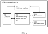
- Fig. 3 shows an illustrative embodiment of a communication device 300, according to the claimed invention.
- the communication device 300 includes a first antenna 302 and a second antenna 304 separate from the first antenna.
- the first antenna 302 is configured to receive and transmit a first set of NFC signals relating to NFC transactions.
- NFC transactions refers to any type of operations which may be carried out using a regular NFC antenna, i.e. an NFC antenna which is not specifically designed for wireless charging operations, and which therefore does not need to meet stringent form factor requirements, for example.
- NFC transactions include payment transactions and public transport ticket validations, which are carried out when an NFC-enabled mobile device (e.g., a phone) is within close proximity of an NFC-enabled terminal.
- the second antenna 304 is configured to receive and transmit a second set of NFC signals, wherein said second set of NFC signals relates to wireless charging operations. For instance, these signals may include signals for controlling a wireless charging operation, and signals which effectively transfer energy to an accessory device.
- the communication device includes a controller 308, an interface 306 between the controller 308 and the first and second antenna 302, 304, and an additional interface 310.
- the interface 306 includes an antenna selection unit 306, which is configured to select the first antenna 302 or the second antenna 304 in response to a selection signal received from the controller 308. Furthermore, the controller 308 is configured to detect whether an external communication device is within communication range of the first antenna 302 using the additional interface 310. By means of the additional interface 310 between the controller 308 and the first antenna 302, the detection of an external communication device in proximity of the first antenna is facilitated, in particular when a wireless charging operation is active (i.e., when the second antenna 304 is being used).
- Fig. 4 shows an illustrative embodiment of a method 400 of operating a communication device, according to the claimed invention.
- the method 400 comprises the following steps: at 402, receiving and transmitting, by a first antenna, a first set of NFC signals, wherein said first set of NFC signals relates to NFC transactions, at 404, receiving and transmitting, by a second antenna separate from the first antenna 302, a second set of NFC signals, wherein said second set of NFC signals relates to wireless charging operations, at 406, selecting, by an antenna selection unit comprised in a first interface between a controller and the first and second antenna, the first antenna or the second antenna in response to a selection signal received from the controller, and at 408, detecting, by the controller, whether an external communication device is within communication range of the first antenna using a second interface between the controller and the first antenna.
- the second interface i.e., the additional interface
- the detection of an external communication device in proximity of the first antenna is facilitated, in particular when a wireless charging operation is active (i.e., when the second antenna 304 is being used).
- an NFC device may be equipped with a single NFC controller, which is connectable to a regular NFC antenna (i.e., a first antenna) and a WLC antenna (i.e., a second antenna).
- the NFC device comprises a first interface having a selection module (i.e., an antenna selection unit) and an additional, second interface, which may also be referred to as a sense interface.
- the sense interface provides RF sense functionality on the regular NFC antenna while the NFC controller's transceiver is connected to the WLC antenna, for example while the WLC antenna actively generates an RF field to perform a wireless charging operation.
- the NFC controller may sense the presence of an external NFC device which is in proximity of the NFC antenna (e.g., an external reader or NFC interrogator).
- the NFC controller may sense, through the sense interface, the presence of other communication counterparts, for example tags or transponders, which may be passive devices, and other NFC target devices.
- the controller is configured to detect whether the external communication device is within communication range of the first antenna by detecting the presence of a radio frequency (RF) field. In this way, detecting an external reader or interrogator is facilitated.
- the controller is configured to conclude that the external communication device is within communication range of the first antenna if the strength of the RF field exceeds a predefined threshold. For instance, the NFC signal strength on the first antenna may be used as a metric. Alternatively, or in addition, a frequency-based metric may be used.
- the sense interface may include an additional receiver stage in the NFC controller, which may also be referred to as an RF sense receiver.
- the controller is configured to detect whether the external communication device is within communication range of the first antenna by detecting a load change on the first antenna. In this way, detecting an external tag or transponder is facilitated.
- an external transponder may be a so-called radio frequency identification (RFID) transponder.
- RFID transponders are widely used, in different areas of industry and commerce and for various purposes.
- RFID transponders may for example be embodied as so-called RFID tags or RFID cards.
- RFID transponders are often passive devices, which means that they do not have their own power source. Instead, they are powered by a field generated by a reader, and they respond to the reader by modulating the field. Thus, in this case, the communication device acts in a reader mode, i.e. it generates a field using its NFC antenna, by means of which the external device is powered. It is noted that RFID transponders are compatible with NFC devices in the sense that they are able to communicate at the same frequency, i.e. 13.56 MHz.
- the sense interface may comprise an additional transmitter stage in the NFC controller, which may also be referred to as an RF sense transmitter.
- the controller is further configured to generate and transmit RF pulses through the first antenna, to detect the load change.
- an external passive device may be detected without consuming a large amount of power.
- a pulse-based technique may include a low power card detection (LPCD) or a low power device detection (LPDD) method for detecting the presence of a passive external device in proximity of the NFC antenna.
- LPCD low power card detection
- LPDD low power device detection
- the controller can for example be configured to use a transmitter supply current as a measure of the load change.
- the NFC controller may be able to detect a load change by generating and transmitting short RF pulses using an additional, separate and basic transmitter stage in the NFC controller.
- a transmitter stage may be basic in the sense that is only capable, for example, of generating a continuous wave signal.
- the transmitter stage may be separate in the sense that it operates independently from the main transmitter stage of the NFC controller (i.e., the transmitter stage integrated in the NFC controller's transceiver).
- the additional transmitter stage has a negligible influence on the NFC controller's transceiver function.
- An additional NFC RF sense receiver matching unit may connect the additional transmitter stage to the NFC antenna.
- an LPCD or LPDD method may be applied, for sensing load changes relative to an initial reference measurement value.
- the transmitter supply current and/or the RF sense receiver interface signal may be used as a metric. In case the transmitter supply current is used, the transmitter current of consecutive RF sense pulses can be monitored. Then, if a significant change of the transmitter current is detected, a wakeup event may be triggered.
- the controller is configured to interrupt an active wireless charging operation if the external communication device is within communication range of the first antenna. In this way, the communication device may quickly initiate and perform an NFC transaction using the NFC antenna.
- the controller is configured to interrupt the active wireless charging operation by instructing the antenna selection unit to select the first antenna.
- the controller is further configured to reactivate the interrupted wireless charging operation if the external communication device is no longer within communication range of the first antenna or if a transaction with the external communication device has concluded. In this way, the wireless charging operation may be resumed quickly.
- the controller is configured to reactivate the interrupted wireless charging operation by instructing the antenna selection unit to select the second antenna.
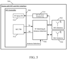
- Fig. 5 shows another illustrative embodiment of a communication device 500, accordinging to the claimed invention.
- the communication device 500 comprises an NFC antenna 502 and a wireless charging antenna 504 separate from the NFC antenna 502.
- the communication device 500 comprises an NFC controller 508, which is connected to the NFC antenna 502 and the wireless charging antenna 504 through an RF matching and antenna selection unit 506.
- the NFC controller 508 comprises an NFC transceiver 512 configured to receive and transmit NFC signals to an external communication device (not shown), using the NFC antenna 502 and the wireless charging antenna 504.
- the communication device 500 comprises a sense interface, which in turn comprises a RF sense receiver stage 510 and an NFC RF sense receiver matching unit 514.
- the embodiment shown in Fig. 5 facilitates detecting whether an external communication device is within communication range of the NFC antenna 502 by detecting the presence of an RF field.
- the communication device 500 includes an additional interface from the NFC antenna 502 to the NFC controller 508.
- An interconnecting NFC RF sense matching unit 514 may be used to convert NFC antenna signals to a voltage or a current that can be sensed by the NFC controller 508.
- the sense interface's receiver stage 510 and interconnecting matching circuitry 514 may be designed such that it acts as a low load to the NFC antenna 502, in order to prevent that the NFC RF link performance is reduced.
- the NFC controller 508 may interrupt an ongoing WLC activity by shutting off the WLC RF field, by connecting the NFC transceiver 512 to the NFC antenna 502 and by handling the detected counterpart in an appropriate manner (e.g., by performing reader mode or card mode NFC transactions). After completing the NFC activity, the NFC controller 508 may reestablish the WLC activity by reconnecting the NFC transceiver 512 to the WLC antenna 504 and by re-establishing communication with the WLC-L counterpart. After the WLC activity has been restored, the sensing function may again be activated through the sense interface.
- Fig. 6 shows a further illustrative embodiment of a communication device 600, according to the claimed invention.
- the communication device 600 comprises an NFC antenna 602 and a wireless charging antenna 604 separate from the NFC antenna 602.
- the communication device 600 comprises an NFC controller 608, which is connected to the NFC antenna 602 and the wireless charging antenna 604 through an RF matching and antenna selection unit 606.
- the NFC controller 608 comprises an NFC transceiver 612 configured to receive and transmit NFC signals to an external communication device (not shown), using the NFC antenna 602 and the wireless charging antenna 604.
- the communication device 600 comprises a sense interface, which in turn comprises an RF sense transmitter stage 610, an NFC device detection receiver sensor 614 and an NFC RF sense matching circuit 616.
- the embodiment shown in Fig. 6 facilitates detecting whether an external communication device is within communication range of the NFC antenna 602 by detecting a load change on the NFC antenna 602. More specifically, compared to the embodiment shown in Fig. 5 , the embodiment shown in Fig. 6 is not only able to detect external RF fields, but also external communication devices acting in card mode like passive transponders. Accordingly, the communication device 600 is able to detect communication counterparts operating in a reader mode and/or communication counterparts operating in a (configurable) card mode, which are close to the NFC antenna 602 during an ongoing wireless charging activity.
- Fig. 7 shows an illustrative embodiment of a timing diagram 700.
- Fig. 7 shows a timing diagram which illustrates the operation of a communication device of the kind set forth, when said communication device is in close proximity of an external NFC reader while it performs a WLC activity.
- Fig. 8 shows another illustrative embodiment of a timing diagram 800.
- Fig. 8 shows a timing diagram which illustrates the operation of a communication device of the kind set forth, when said communication device is in close proximity of an external transponder while it performs a WLC activity.
Landscapes
- Engineering & Computer Science (AREA)
- Computer Networks & Wireless Communication (AREA)
- Signal Processing (AREA)
- Power Engineering (AREA)
- Near-Field Transmission Systems (AREA)
- Telephone Function (AREA)
Claims (15)
- Kommunikationseinrichtung (300), umfassend:eine erste Antenne (302), die ausgelegt ist zum Empfangen und Senden einer ersten Menge von Nahfeldkommunikations-, NFC-, Signalen, wobei die erste Menge von NFC-Signalen zu NFC-Transaktionen in Beziehung steht;eine zweite Antenne (304), die von der ersten Antenne (302) getrennt ist, wobei die zweite Antenne (304) ausgelegt ist zum Empfangen und Senden einer zweiten Menge von NFC-Signalen, wobei die zweite Menge von NFC-Signalen zu Drahtlosladeoperationen in Beziehung steht;einen Controller (308);eine erste Schnittstelle (306) zwischen dem Controller (308) und der ersten und zweiten Antenne, wobei die erste Schnittstelle (306) eine Antennenwahleinheit umfasst, die ausgelegt ist zum Wählen der ersten Antenne (302) oder der zweiten Antenne (304) als Reaktion auf ein von dem Controller (308) empfangenes Wahlsignal;eine zweite Schnittstelle (310) zwischen dem Controller (308) und der ersten Antenne (302);wobei der Controller (308) ausgelegt ist zum Detektieren, ob sich eine externe Kommunikationseinrichtung innerhalb eines Kommunikationsbereichs der ersten Antenne (302) befindet, unter Verwendung der zweiten Schnittstelle (304).
- Kommunikationseinrichtung (300) nach Anspruch 1, wobei der Controller (308) ausgelegt ist zum Detektieren, ob sich die externe Kommunikationseinrichtung innerhalb eines Kommunikationsbereichs der ersten Antenne (302) befindet, durch Detektieren der Anwesenheit eines Hochfrequenz-, HF-, Felds.
- Kommunikationseinrichtung (300) nach Anspruch 1 oder 2, wobei der Controller (308) ausgelegt ist zu folgern, dass sich die externe Kommunikationseinrichtung innerhalb eines Kommunikationsbereichs der ersten Antenne (302) befindet, falls die Stärke des HF-Felds einen vordefinierten Schwellwert übersteigt.
- Kommunikationseinrichtung (300) nach einem vorhergehenden Anspruch, wobei der Controller (308) ausgelegt ist zu detektieren, ob sich die externe Kommunikationseinrichtung innerhalb eines Kommunikationsbereichs der ersten Antenne (302) befindet, durch Detektieren eines Lastwechsels an der ersten Antenne.
- Kommunikationseinrichtung (300) nach Anspruch 4, wobei der Controller (308) weiter ausgelegt ist zum Generieren und Senden von Hochfrequenz-, HF-, Impulsen durch die erste Antenne (302), um den Lastwechsel an der ersten Antenne (302) zu detektieren.
- Kommunikationseinrichtung (300) nach Anspruch 4 oder 5, wobei der Controller (308) ausgelegt ist zum Verwenden eines Senderversorgungsstroms als ein Maß für den Lastwechsel.
- Kommunikationseinrichtung (300) nach einem vorhergehenden Anspruch, wobei der Controller (308) ausgelegt ist zum Unterbrechen einer aktiven Drahtlosladeoperation, falls sich die externe Kommunikationseinrichtung innerhalb eines Kommunikationsbereichs der ersten Antenne (302) befindet.
- Kommunikationseinrichtung (300) nach Anspruch 7, wobei der Controller (308) ausgelegt ist zum Unterbrechen der aktiven Drahtlosladeoperation, indem die Antennenwahleinheit angewiesen wird, die erste Antenne (302) zu wählen.
- Kommunikationseinrichtung (300) nach Anspruch 7 oder 8, wobei der Controller (308) weiter ausgelegt ist zum Reaktivieren der unterbrochenen Drahtlosladeoperation, falls sich die externe Kommunikationseinrichtung nicht länger innerhalb eines Kommunikationsbereichs der ersten Antenne (302) befindet oder falls eine Transaktion mit der externen Kommunikationseinrichtung abgeschlossen worden ist.
- Kommunikationseinrichtung (300) nach Anspruch 9, wobei der Controller (308) ausgelegt ist zum Reaktivieren der unterbrochenen Drahtlosladeoperation, indem die Antennenwahleinheit angewiesen wird, die zweite Antenne (304) zu wählen.
- Kommunikationseinrichtung (300) nach einem vorhergehenden Anspruch, wobei die erste Schnittstelle (306) eine erste Anpassungsschaltung umfasst und die zweite Schnittstelle (310) eine zweite Anpassungsschaltung umfasst.
- Kommunikationseinrichtung (300) nach einem vorhergehenden Anspruch, die eine mobile Einrichtung ist.
- Verfahren (400) zum Betreiben einer Kommunikationseinrichtung, umfassend:Empfangen und Senden (402), durch eine erste Antenne, einer ersten Menge von NFC-Signalen, wobei die erste Menge von NFC-Signalen zu NFC-Transaktionen in Beziehung steht;Empfangen und Senden (404) durch eine von der ersten Antenne getrennte zweite Antenne einer zweiten Menge von NFC-Signalen, wobei die zweite Menge von NFC-Signalen zu Drahtlosladeoperationen in Beziehung steht;Wählen (406) durch eine Antennenwahleinheit, die in einer ersten Schnittstelle zwischen einem Controller und der ersten und zweiten Antenne enthalten ist, der ersten Antenne oder der zweiten Antenne als Reaktion auf ein von dem Controller empfangenes Wahlsignal;Detektieren (408) durch den Controller, ob sich eine externe Kommunikationseinrichtung innerhalb eines Kommunikationsbereichs der ersten Antenne befindet, unter Verwendung einer zweiten Schnittstelle zwischen dem Controller und der ersten Antenne.
- Verfahren (400) nach Anspruch 13, wobei das Detektieren (408) das Detektieren der Anwesenheit eines Hochfrequenz-, HF-, Felds umfasst.
- Verfahren (400) nach Anspruch 13 oder 14, wobei das Detektieren (408) das Detektieren einer Laständerung an der ersten Antenne umfasst.
Priority Applications (3)
| Application Number | Priority Date | Filing Date | Title |
|---|---|---|---|
| EP20167897.6A EP3890196B1 (de) | 2020-04-03 | 2020-04-03 | Vorrichtung und methode zur kommunikation und drahtlosem laden |
| CN202110257101.7A CN113497641B (zh) | 2020-04-03 | 2021-03-04 | 通信装置和操作方法 |
| US17/207,839 US11784681B2 (en) | 2020-04-03 | 2021-03-22 | Communication device and operating method |
Applications Claiming Priority (1)
| Application Number | Priority Date | Filing Date | Title |
|---|---|---|---|
| EP20167897.6A EP3890196B1 (de) | 2020-04-03 | 2020-04-03 | Vorrichtung und methode zur kommunikation und drahtlosem laden |
Publications (2)
| Publication Number | Publication Date |
|---|---|
| EP3890196A1 EP3890196A1 (de) | 2021-10-06 |
| EP3890196B1 true EP3890196B1 (de) | 2023-06-21 |
Family
ID=70165931
Family Applications (1)
| Application Number | Title | Priority Date | Filing Date |
|---|---|---|---|
| EP20167897.6A Active EP3890196B1 (de) | 2020-04-03 | 2020-04-03 | Vorrichtung und methode zur kommunikation und drahtlosem laden |
Country Status (3)
| Country | Link |
|---|---|
| US (1) | US11784681B2 (de) |
| EP (1) | EP3890196B1 (de) |
| CN (1) | CN113497641B (de) |
Families Citing this family (9)
| Publication number | Priority date | Publication date | Assignee | Title |
|---|---|---|---|---|
| EP3863185A1 (de) | 2020-02-07 | 2021-08-11 | Nxp B.V. | Kommunikationsvorrichtung und verfahren zu deren betrieb |
| US20210376881A1 (en) * | 2020-05-29 | 2021-12-02 | Shure Acquisition Holdings, Inc. | Wearable Device With Conductive Coil for Wireless Charging and Communicating |
| KR102918419B1 (ko) * | 2021-04-20 | 2026-01-26 | 삼성전자주식회사 | Nfc 장치, nfc 장치 동작 방법 및 상기 nfc 장치를 포함하는 통신 시스템 |
| US12445168B2 (en) * | 2022-03-31 | 2025-10-14 | Chengdu Boe Optoelectronics Technology Co., Ltd. | Display apparatus and control method thereof |
| US12407195B2 (en) | 2022-09-30 | 2025-09-02 | Nxp B.V. | Method and device for performing a presence check for wireless charging listener devices |
| CN117278071B (zh) * | 2023-11-21 | 2024-01-23 | 深圳市天龙世纪科技发展有限公司 | 一种基于nfc的兼容性天线的控制方法、系统和存储介质 |
| CN118153598B (zh) * | 2024-02-06 | 2024-11-29 | 支付宝(杭州)信息技术有限公司 | 一种协助读卡器实现寻卡的方法、寻卡方法及nfc标签 |
| CN119892260B (zh) * | 2024-02-06 | 2026-03-24 | 支付宝(杭州)数字服务技术有限公司 | Nfc电场检测系统、方法和nfc设备 |
| EP4708629A1 (de) * | 2024-09-10 | 2026-03-11 | Nxp B.V. | Verfahren und system zur drahtlosen ladeunterbrechung und wiederaufnahme |
Family Cites Families (39)
| Publication number | Priority date | Publication date | Assignee | Title |
|---|---|---|---|---|
| GB0501115D0 (en) | 2005-01-19 | 2005-02-23 | Innovision Res & Tech Plc | Combined power coupling and rf communication apparatus |
| DE602006006978D1 (de) * | 2005-02-09 | 2009-07-09 | Nxp Bv | Verfahren zur sicherstellung einer sicheren nfc-funktionalität einer drahtlosen mobilen kommunikationsvorrichtung und drahtlose mobile kommunikationsvorrichtung mit sicherer nfc-funktionalität |
| US9240824B2 (en) * | 2009-02-13 | 2016-01-19 | Qualcomm Incorporated | Wireless power and wireless communication for electronic devices |
| US10079090B2 (en) * | 2010-12-01 | 2018-09-18 | Triune Systems, LLC | Multiple coil data transmission system |
| US8983374B2 (en) * | 2010-12-13 | 2015-03-17 | Qualcomm Incorporated | Receiver for near field communication and wireless power functionalities |
| CN106887883B (zh) * | 2012-02-29 | 2019-08-23 | 松下知识产权经营株式会社 | 充电装置 |
| BR122016030280A2 (pt) * | 2012-03-15 | 2019-08-27 | Intel Corp | dispositivo eletrônico portátil, dispositivo eletrônico e sistema |
| KR101192665B1 (ko) * | 2012-04-03 | 2012-10-19 | 주식회사 맥스웨이브 | 근거리 무선 통신과 무선 충전을 위한 공용 안테나를 이용한 휴대 장치 |
| KR101828308B1 (ko) | 2012-07-03 | 2018-02-12 | 삼성전자 주식회사 | 안테나 제어 시스템과 이를 포함하는 단말기 및 안테나 제어 방법 |
| US9106268B2 (en) * | 2012-09-12 | 2015-08-11 | Qualcomm Incorporated | Methods and apparatus for improving acquisition for NFC load modulation |
| CN103117813A (zh) * | 2012-10-18 | 2013-05-22 | 中兴通讯股份有限公司 | 一种用户终端以及控制nfc单元与无线充电单元切换的方法 |
| US9042816B2 (en) * | 2012-11-05 | 2015-05-26 | Qualcomm Incorporated | Methods and apparatus for improving NFC coil tuning based on proximity to a remote NFC device |
| US9660478B2 (en) * | 2012-12-12 | 2017-05-23 | Qualcomm Incorporated | System and method for facilitating avoidance of wireless charging cross connection |
| US9419465B2 (en) * | 2013-01-07 | 2016-08-16 | Nxp B.V. | Wireless charger |
| KR20140112231A (ko) * | 2013-03-13 | 2014-09-23 | 삼성전자주식회사 | 휴대 단말기에서 근접 무선 통신을 위한 안테나를 연결하는 장치 및 방법 |
| JP6130711B2 (ja) * | 2013-04-17 | 2017-05-17 | キヤノン株式会社 | 通信装置、制御方法、及びプログラム |
| US9685699B2 (en) * | 2013-05-21 | 2017-06-20 | Microsoft Technology Licensing, Llc | Integrated antenna for wireless communications and wireless charging |
| EP3042452B1 (de) * | 2013-08-09 | 2018-10-03 | Intel Corporation | Spule für kontextgesteuerte schaltung und drahtloses laden einer mobilen vorrichtung |
| KR102324342B1 (ko) * | 2014-12-24 | 2021-11-10 | 삼성에스디아이 주식회사 | 무선 충전과 근거리 통신 기능을 갖는 배터리 팩 |
| KR102276841B1 (ko) * | 2015-01-14 | 2021-07-14 | 삼성전자주식회사 | 안테나 장치 및 그 제어 방법 |
| TWM508155U (zh) * | 2015-06-10 | 2015-09-01 | 駿達電通股份有限公司 | 近場通訊無線充電裝置 |
| US10707703B2 (en) * | 2015-07-20 | 2020-07-07 | Amotech Co., Ltd. | Combination antenna module and portable electronic device including same |
| WO2017014467A1 (ko) * | 2015-07-20 | 2017-01-26 | 주식회사 아모텍 | 콤보 안테나모듈 및 이를 포함하는 휴대용 전자장치 |
| US10248899B2 (en) * | 2015-10-06 | 2019-04-02 | Witricity Corporation | RFID tag and transponder detection in wireless energy transfer systems |
| KR102440975B1 (ko) * | 2016-01-21 | 2022-09-07 | 삼성전자주식회사 | 전자 장치 및 전자 장치에서 근거리 무선 통신을 위한 방법 |
| KR102548688B1 (ko) * | 2016-03-28 | 2023-06-28 | 삼성전자주식회사 | 누설 전력 처리 방법 및 이를 지원하는 전자 장치 |
| KR101846953B1 (ko) * | 2016-04-06 | 2018-04-09 | 주식회사 맵스 | 보호 기능을 가진 통신장치 및 전자장치 |
| WO2017217686A1 (en) * | 2016-06-16 | 2017-12-21 | Samsung Electronics Co., Ltd. | Wireless power transmitter, wireless power receiver, and control methods thereof |
| US9787366B1 (en) * | 2016-06-29 | 2017-10-10 | Intel Corporation | Near field communication detection in wireless charging systems |
| EP3280060B1 (de) * | 2016-08-02 | 2020-01-01 | Nxp B.V. | Vorrichtungserkennung mit harmonischen |
| KR102516883B1 (ko) | 2016-08-04 | 2023-04-03 | 삼성전자주식회사 | 차폐 구조를 포함하는 전자 장치 |
| CN109565185B (zh) * | 2016-08-05 | 2022-10-14 | 夏普株式会社 | 通信装置、控制程序以及非接触供电系统 |
| CN107547103A (zh) | 2016-12-23 | 2018-01-05 | 西安闻泰电子科技有限公司 | Nfc与无线充电共用天线的系统及方法 |
| CN107565216A (zh) * | 2017-08-29 | 2018-01-09 | 广州三星通信技术研究有限公司 | 电子设备的外壳及电子设备 |
| KR102381435B1 (ko) * | 2017-10-30 | 2022-03-31 | 삼성전자주식회사 | 전자기 간섭 검출을 위한 안테나 및 그것을 포함하는 휴대용 전자 장치 |
| CN107872101B (zh) * | 2017-11-24 | 2019-11-15 | 深圳市文鼎创数据科技有限公司 | 一种nfc天线取电装置 |
| KR102564363B1 (ko) * | 2018-07-27 | 2023-08-08 | 삼성전자 주식회사 | 외부 전자 장치로부터 수신된 식별 정보에 기반하여 무선 충전과 관련된 통신 채널을 제어하는 전자 장치 및 전자 장치의 동작 방법 |
| KR102541839B1 (ko) * | 2018-07-31 | 2023-06-09 | 삼성전자 주식회사 | 적층되어 형성된 다수의 코일 안테나들을 갖는 전자 장치 |
| US10997483B2 (en) * | 2019-06-12 | 2021-05-04 | Stmicroelectronics, Inc | NFC antenna switch |
-
2020
- 2020-04-03 EP EP20167897.6A patent/EP3890196B1/de active Active
-
2021
- 2021-03-04 CN CN202110257101.7A patent/CN113497641B/zh active Active
- 2021-03-22 US US17/207,839 patent/US11784681B2/en active Active
Also Published As
| Publication number | Publication date |
|---|---|
| CN113497641B (zh) | 2024-09-10 |
| US11784681B2 (en) | 2023-10-10 |
| US20210314028A1 (en) | 2021-10-07 |
| EP3890196A1 (de) | 2021-10-06 |
| CN113497641A (zh) | 2021-10-12 |
Similar Documents
| Publication | Publication Date | Title |
|---|---|---|
| EP3890196B1 (de) | Vorrichtung und methode zur kommunikation und drahtlosem laden | |
| US8446257B2 (en) | Radio frequency charging system | |
| EP2541995B1 (de) | Methode und Vorrichtung zur Reduzierung des Energieverbrauchs eines durch NFC mit Energie versorgten Apparats | |
| EP1834394B1 (de) | Verfahren und vorrichtung zur nahfeldkommunikation | |
| EP3139667B1 (de) | Hybride RF Abfrageschleife für NFC-Vorrichtung und Wiederholungsmechanismus | |
| US20120045989A1 (en) | Device discovery in near-field communication | |
| US20090093272A1 (en) | Device, Module and Method for Shared Antenna Operation In a Rfid Technology Based Communication Environment | |
| US11411611B2 (en) | Communication device and method for operating the same | |
| US11916616B2 (en) | Near field communication device having an event detector | |
| CN102044028A (zh) | 移动支付的实现方法及移动支付系统 | |
| US20260081644A1 (en) | System and method for distinguishing between active and passive nfc devices | |
| EP3996425B1 (de) | Rf-kommunikationsgeräte und betriebsmethoden | |
| WO2012053203A1 (ja) | 近距離無線通信装置 | |
| EP3780404A1 (de) | Hbc-vorrichtung und verfahren für nfc-signal | |
| CN115280320A (zh) | 用于识别无源rfid卡的方法 | |
| US20240086891A1 (en) | Near-field communication device | |
| US20250023395A1 (en) | Wireless charging device and operating method | |
| US12327157B2 (en) | Techniques for managing physical cards stored in a physical wallet | |
| KR101192168B1 (ko) | 근거리 무선통신방법 | |
| CN117692029A (zh) | 近场通信设备 |
Legal Events
| Date | Code | Title | Description |
|---|---|---|---|
| PUAI | Public reference made under article 153(3) epc to a published international application that has entered the european phase |
Free format text: ORIGINAL CODE: 0009012 |
|
| STAA | Information on the status of an ep patent application or granted ep patent |
Free format text: STATUS: THE APPLICATION HAS BEEN PUBLISHED |
|
| AK | Designated contracting states |
Kind code of ref document: A1 Designated state(s): AL AT BE BG CH CY CZ DE DK EE ES FI FR GB GR HR HU IE IS IT LI LT LU LV MC MK MT NL NO PL PT RO RS SE SI SK SM TR |
|
| STAA | Information on the status of an ep patent application or granted ep patent |
Free format text: STATUS: REQUEST FOR EXAMINATION WAS MADE |
|
| 17P | Request for examination filed |
Effective date: 20220406 |
|
| RBV | Designated contracting states (corrected) |
Designated state(s): AL AT BE BG CH CY CZ DE DK EE ES FI FR GB GR HR HU IE IS IT LI LT LU LV MC MK MT NL NO PL PT RO RS SE SI SK SM TR |
|
| GRAP | Despatch of communication of intention to grant a patent |
Free format text: ORIGINAL CODE: EPIDOSNIGR1 |
|
| STAA | Information on the status of an ep patent application or granted ep patent |
Free format text: STATUS: GRANT OF PATENT IS INTENDED |
|
| RIC1 | Information provided on ipc code assigned before grant |
Ipc: H02J 50/90 20160101ALI20230313BHEP Ipc: H02J 7/00 20060101ALI20230313BHEP Ipc: H02J 50/10 20160101ALI20230313BHEP Ipc: H02J 50/60 20160101ALI20230313BHEP Ipc: H04B 5/00 20060101AFI20230313BHEP |
|
| INTG | Intention to grant announced |
Effective date: 20230327 |
|
| GRAS | Grant fee paid |
Free format text: ORIGINAL CODE: EPIDOSNIGR3 |
|
| GRAA | (expected) grant |
Free format text: ORIGINAL CODE: 0009210 |
|
| STAA | Information on the status of an ep patent application or granted ep patent |
Free format text: STATUS: THE PATENT HAS BEEN GRANTED |
|
| AK | Designated contracting states |
Kind code of ref document: B1 Designated state(s): AL AT BE BG CH CY CZ DE DK EE ES FI FR GB GR HR HU IE IS IT LI LT LU LV MC MK MT NL NO PL PT RO RS SE SI SK SM TR |
|
| REG | Reference to a national code |
Ref country code: CH Ref legal event code: EP |
|
| REG | Reference to a national code |
Ref country code: DE Ref legal event code: R096 Ref document number: 602020012661 Country of ref document: DE |
|
| REG | Reference to a national code |
Ref country code: AT Ref legal event code: REF Ref document number: 1581646 Country of ref document: AT Kind code of ref document: T Effective date: 20230715 |
|
| REG | Reference to a national code |
Ref country code: IE Ref legal event code: FG4D |
|
| REG | Reference to a national code |
Ref country code: LT Ref legal event code: MG9D |
|
| P01 | Opt-out of the competence of the unified patent court (upc) registered |
Effective date: 20230907 |
|
| REG | Reference to a national code |
Ref country code: NL Ref legal event code: MP Effective date: 20230621 |
|
| PG25 | Lapsed in a contracting state [announced via postgrant information from national office to epo] |
Ref country code: SE Free format text: LAPSE BECAUSE OF FAILURE TO SUBMIT A TRANSLATION OF THE DESCRIPTION OR TO PAY THE FEE WITHIN THE PRESCRIBED TIME-LIMIT Effective date: 20230621 Ref country code: NO Free format text: LAPSE BECAUSE OF FAILURE TO SUBMIT A TRANSLATION OF THE DESCRIPTION OR TO PAY THE FEE WITHIN THE PRESCRIBED TIME-LIMIT Effective date: 20230921 |
|
| REG | Reference to a national code |
Ref country code: AT Ref legal event code: MK05 Ref document number: 1581646 Country of ref document: AT Kind code of ref document: T Effective date: 20230621 |
|
| PG25 | Lapsed in a contracting state [announced via postgrant information from national office to epo] |
Ref country code: RS Free format text: LAPSE BECAUSE OF FAILURE TO SUBMIT A TRANSLATION OF THE DESCRIPTION OR TO PAY THE FEE WITHIN THE PRESCRIBED TIME-LIMIT Effective date: 20230621 Ref country code: NL Free format text: LAPSE BECAUSE OF FAILURE TO SUBMIT A TRANSLATION OF THE DESCRIPTION OR TO PAY THE FEE WITHIN THE PRESCRIBED TIME-LIMIT Effective date: 20230621 Ref country code: LV Free format text: LAPSE BECAUSE OF FAILURE TO SUBMIT A TRANSLATION OF THE DESCRIPTION OR TO PAY THE FEE WITHIN THE PRESCRIBED TIME-LIMIT Effective date: 20230621 Ref country code: LT Free format text: LAPSE BECAUSE OF FAILURE TO SUBMIT A TRANSLATION OF THE DESCRIPTION OR TO PAY THE FEE WITHIN THE PRESCRIBED TIME-LIMIT Effective date: 20230621 Ref country code: HR Free format text: LAPSE BECAUSE OF FAILURE TO SUBMIT A TRANSLATION OF THE DESCRIPTION OR TO PAY THE FEE WITHIN THE PRESCRIBED TIME-LIMIT Effective date: 20230621 Ref country code: GR Free format text: LAPSE BECAUSE OF FAILURE TO SUBMIT A TRANSLATION OF THE DESCRIPTION OR TO PAY THE FEE WITHIN THE PRESCRIBED TIME-LIMIT Effective date: 20230922 |
|
| PG25 | Lapsed in a contracting state [announced via postgrant information from national office to epo] |
Ref country code: FI Free format text: LAPSE BECAUSE OF FAILURE TO SUBMIT A TRANSLATION OF THE DESCRIPTION OR TO PAY THE FEE WITHIN THE PRESCRIBED TIME-LIMIT Effective date: 20230621 |
|
| PG25 | Lapsed in a contracting state [announced via postgrant information from national office to epo] |
Ref country code: SK Free format text: LAPSE BECAUSE OF FAILURE TO SUBMIT A TRANSLATION OF THE DESCRIPTION OR TO PAY THE FEE WITHIN THE PRESCRIBED TIME-LIMIT Effective date: 20230621 |
|
| PG25 | Lapsed in a contracting state [announced via postgrant information from national office to epo] |
Ref country code: ES Free format text: LAPSE BECAUSE OF FAILURE TO SUBMIT A TRANSLATION OF THE DESCRIPTION OR TO PAY THE FEE WITHIN THE PRESCRIBED TIME-LIMIT Effective date: 20230621 |
|
| PG25 | Lapsed in a contracting state [announced via postgrant information from national office to epo] |
Ref country code: IS Free format text: LAPSE BECAUSE OF FAILURE TO SUBMIT A TRANSLATION OF THE DESCRIPTION OR TO PAY THE FEE WITHIN THE PRESCRIBED TIME-LIMIT Effective date: 20231021 |
|
| PG25 | Lapsed in a contracting state [announced via postgrant information from national office to epo] |
Ref country code: SM Free format text: LAPSE BECAUSE OF FAILURE TO SUBMIT A TRANSLATION OF THE DESCRIPTION OR TO PAY THE FEE WITHIN THE PRESCRIBED TIME-LIMIT Effective date: 20230621 Ref country code: SK Free format text: LAPSE BECAUSE OF FAILURE TO SUBMIT A TRANSLATION OF THE DESCRIPTION OR TO PAY THE FEE WITHIN THE PRESCRIBED TIME-LIMIT Effective date: 20230621 Ref country code: RO Free format text: LAPSE BECAUSE OF FAILURE TO SUBMIT A TRANSLATION OF THE DESCRIPTION OR TO PAY THE FEE WITHIN THE PRESCRIBED TIME-LIMIT Effective date: 20230621 Ref country code: PT Free format text: LAPSE BECAUSE OF FAILURE TO SUBMIT A TRANSLATION OF THE DESCRIPTION OR TO PAY THE FEE WITHIN THE PRESCRIBED TIME-LIMIT Effective date: 20231023 Ref country code: IS Free format text: LAPSE BECAUSE OF FAILURE TO SUBMIT A TRANSLATION OF THE DESCRIPTION OR TO PAY THE FEE WITHIN THE PRESCRIBED TIME-LIMIT Effective date: 20231021 Ref country code: ES Free format text: LAPSE BECAUSE OF FAILURE TO SUBMIT A TRANSLATION OF THE DESCRIPTION OR TO PAY THE FEE WITHIN THE PRESCRIBED TIME-LIMIT Effective date: 20230621 Ref country code: EE Free format text: LAPSE BECAUSE OF FAILURE TO SUBMIT A TRANSLATION OF THE DESCRIPTION OR TO PAY THE FEE WITHIN THE PRESCRIBED TIME-LIMIT Effective date: 20230621 Ref country code: CZ Free format text: LAPSE BECAUSE OF FAILURE TO SUBMIT A TRANSLATION OF THE DESCRIPTION OR TO PAY THE FEE WITHIN THE PRESCRIBED TIME-LIMIT Effective date: 20230621 Ref country code: AT Free format text: LAPSE BECAUSE OF FAILURE TO SUBMIT A TRANSLATION OF THE DESCRIPTION OR TO PAY THE FEE WITHIN THE PRESCRIBED TIME-LIMIT Effective date: 20230621 |
|
| PG25 | Lapsed in a contracting state [announced via postgrant information from national office to epo] |
Ref country code: PL Free format text: LAPSE BECAUSE OF FAILURE TO SUBMIT A TRANSLATION OF THE DESCRIPTION OR TO PAY THE FEE WITHIN THE PRESCRIBED TIME-LIMIT Effective date: 20230621 |
|
| REG | Reference to a national code |
Ref country code: DE Ref legal event code: R097 Ref document number: 602020012661 Country of ref document: DE |
|
| PLBE | No opposition filed within time limit |
Free format text: ORIGINAL CODE: 0009261 |
|
| STAA | Information on the status of an ep patent application or granted ep patent |
Free format text: STATUS: NO OPPOSITION FILED WITHIN TIME LIMIT |
|
| PG25 | Lapsed in a contracting state [announced via postgrant information from national office to epo] |
Ref country code: DK Free format text: LAPSE BECAUSE OF FAILURE TO SUBMIT A TRANSLATION OF THE DESCRIPTION OR TO PAY THE FEE WITHIN THE PRESCRIBED TIME-LIMIT Effective date: 20230621 |
|
| PG25 | Lapsed in a contracting state [announced via postgrant information from national office to epo] |
Ref country code: SI Free format text: LAPSE BECAUSE OF FAILURE TO SUBMIT A TRANSLATION OF THE DESCRIPTION OR TO PAY THE FEE WITHIN THE PRESCRIBED TIME-LIMIT Effective date: 20230621 |
|
| 26N | No opposition filed |
Effective date: 20240322 |
|
| PG25 | Lapsed in a contracting state [announced via postgrant information from national office to epo] |
Ref country code: SI Free format text: LAPSE BECAUSE OF FAILURE TO SUBMIT A TRANSLATION OF THE DESCRIPTION OR TO PAY THE FEE WITHIN THE PRESCRIBED TIME-LIMIT Effective date: 20230621 Ref country code: IT Free format text: LAPSE BECAUSE OF FAILURE TO SUBMIT A TRANSLATION OF THE DESCRIPTION OR TO PAY THE FEE WITHIN THE PRESCRIBED TIME-LIMIT Effective date: 20230621 |
|
| PG25 | Lapsed in a contracting state [announced via postgrant information from national office to epo] |
Ref country code: BG Free format text: LAPSE BECAUSE OF FAILURE TO SUBMIT A TRANSLATION OF THE DESCRIPTION OR TO PAY THE FEE WITHIN THE PRESCRIBED TIME-LIMIT Effective date: 20230621 |
|
| PG25 | Lapsed in a contracting state [announced via postgrant information from national office to epo] |
Ref country code: MC Free format text: LAPSE BECAUSE OF FAILURE TO SUBMIT A TRANSLATION OF THE DESCRIPTION OR TO PAY THE FEE WITHIN THE PRESCRIBED TIME-LIMIT Effective date: 20230621 |
|
| PG25 | Lapsed in a contracting state [announced via postgrant information from national office to epo] |
Ref country code: MC Free format text: LAPSE BECAUSE OF FAILURE TO SUBMIT A TRANSLATION OF THE DESCRIPTION OR TO PAY THE FEE WITHIN THE PRESCRIBED TIME-LIMIT Effective date: 20230621 Ref country code: BG Free format text: LAPSE BECAUSE OF FAILURE TO SUBMIT A TRANSLATION OF THE DESCRIPTION OR TO PAY THE FEE WITHIN THE PRESCRIBED TIME-LIMIT Effective date: 20230621 |
|
| REG | Reference to a national code |
Ref country code: CH Ref legal event code: PL |
|
| PG25 | Lapsed in a contracting state [announced via postgrant information from national office to epo] |
Ref country code: LU Free format text: LAPSE BECAUSE OF NON-PAYMENT OF DUE FEES Effective date: 20240403 |
|
| GBPC | Gb: european patent ceased through non-payment of renewal fee |
Effective date: 20240403 |
|
| REG | Reference to a national code |
Ref country code: BE Ref legal event code: MM Effective date: 20240430 |
|
| PG25 | Lapsed in a contracting state [announced via postgrant information from national office to epo] |
Ref country code: LU Free format text: LAPSE BECAUSE OF NON-PAYMENT OF DUE FEES Effective date: 20240403 |
|
| PG25 | Lapsed in a contracting state [announced via postgrant information from national office to epo] |
Ref country code: BE Free format text: LAPSE BECAUSE OF NON-PAYMENT OF DUE FEES Effective date: 20240430 |
|
| PG25 | Lapsed in a contracting state [announced via postgrant information from national office to epo] |
Ref country code: GB Free format text: LAPSE BECAUSE OF NON-PAYMENT OF DUE FEES Effective date: 20240403 |
|
| PG25 | Lapsed in a contracting state [announced via postgrant information from national office to epo] |
Ref country code: GB Free format text: LAPSE BECAUSE OF NON-PAYMENT OF DUE FEES Effective date: 20240403 Ref country code: BE Free format text: LAPSE BECAUSE OF NON-PAYMENT OF DUE FEES Effective date: 20240430 Ref country code: CH Free format text: LAPSE BECAUSE OF NON-PAYMENT OF DUE FEES Effective date: 20240430 |
|
| PG25 | Lapsed in a contracting state [announced via postgrant information from national office to epo] |
Ref country code: IE Free format text: LAPSE BECAUSE OF NON-PAYMENT OF DUE FEES Effective date: 20240403 |
|
| PGFP | Annual fee paid to national office [announced via postgrant information from national office to epo] |
Ref country code: DE Payment date: 20250319 Year of fee payment: 6 |
|
| PG25 | Lapsed in a contracting state [announced via postgrant information from national office to epo] |
Ref country code: CY Free format text: LAPSE BECAUSE OF FAILURE TO SUBMIT A TRANSLATION OF THE DESCRIPTION OR TO PAY THE FEE WITHIN THE PRESCRIBED TIME-LIMIT; INVALID AB INITIO Effective date: 20200403 |
|
| PG25 | Lapsed in a contracting state [announced via postgrant information from national office to epo] |
Ref country code: HU Free format text: LAPSE BECAUSE OF FAILURE TO SUBMIT A TRANSLATION OF THE DESCRIPTION OR TO PAY THE FEE WITHIN THE PRESCRIBED TIME-LIMIT; INVALID AB INITIO Effective date: 20200403 |
|
| PG25 | Lapsed in a contracting state [announced via postgrant information from national office to epo] |
Ref country code: TR Free format text: LAPSE BECAUSE OF FAILURE TO SUBMIT A TRANSLATION OF THE DESCRIPTION OR TO PAY THE FEE WITHIN THE PRESCRIBED TIME-LIMIT Effective date: 20230621 |
|
| PGFP | Annual fee paid to national office [announced via postgrant information from national office to epo] |
Ref country code: FR Payment date: 20260319 Year of fee payment: 7 |