EP3890230A1 - Procédé de planification améliorée de ressources de réseau pour des équipements utilisateur à capacité réduite - Google Patents
Procédé de planification améliorée de ressources de réseau pour des équipements utilisateur à capacité réduite Download PDFInfo
- Publication number
- EP3890230A1 EP3890230A1 EP20167592.3A EP20167592A EP3890230A1 EP 3890230 A1 EP3890230 A1 EP 3890230A1 EP 20167592 A EP20167592 A EP 20167592A EP 3890230 A1 EP3890230 A1 EP 3890230A1
- Authority
- EP
- European Patent Office
- Prior art keywords
- frequency band
- base station
- scheduled
- user equipment
- downlink
- Prior art date
- Legal status (The legal status is an assumption and is not a legal conclusion. Google has not performed a legal analysis and makes no representation as to the accuracy of the status listed.)
- Withdrawn
Links
Images


Classifications
-
- H—ELECTRICITY
- H04—ELECTRIC COMMUNICATION TECHNIQUE
- H04L—TRANSMISSION OF DIGITAL INFORMATION, e.g. TELEGRAPHIC COMMUNICATION
- H04L5/00—Arrangements affording multiple use of the transmission path
- H04L5/14—Two-way operation using the same type of signal, i.e. duplex
- H04L5/143—Two-way operation using the same type of signal, i.e. duplex for modulated signals
-
- H—ELECTRICITY
- H04—ELECTRIC COMMUNICATION TECHNIQUE
- H04L—TRANSMISSION OF DIGITAL INFORMATION, e.g. TELEGRAPHIC COMMUNICATION
- H04L5/00—Arrangements affording multiple use of the transmission path
- H04L5/0091—Signalling for the administration of the divided path, e.g. signalling of configuration information
- H04L5/0094—Indication of how sub-channels of the path are allocated
-
- H—ELECTRICITY
- H04—ELECTRIC COMMUNICATION TECHNIQUE
- H04L—TRANSMISSION OF DIGITAL INFORMATION, e.g. TELEGRAPHIC COMMUNICATION
- H04L5/00—Arrangements affording multiple use of the transmission path
- H04L5/14—Two-way operation using the same type of signal, i.e. duplex
- H04L5/1438—Negotiation of transmission parameters prior to communication
-
- H—ELECTRICITY
- H04—ELECTRIC COMMUNICATION TECHNIQUE
- H04L—TRANSMISSION OF DIGITAL INFORMATION, e.g. TELEGRAPHIC COMMUNICATION
- H04L5/00—Arrangements affording multiple use of the transmission path
- H04L5/14—Two-way operation using the same type of signal, i.e. duplex
- H04L5/1469—Two-way operation using the same type of signal, i.e. duplex using time-sharing
-
- H—ELECTRICITY
- H04—ELECTRIC COMMUNICATION TECHNIQUE
- H04W—WIRELESS COMMUNICATION NETWORKS
- H04W72/00—Local resource management
- H04W72/12—Wireless traffic scheduling
- H04W72/1263—Mapping of traffic onto schedule, e.g. scheduled allocation or multiplexing of flows
-
- H—ELECTRICITY
- H04—ELECTRIC COMMUNICATION TECHNIQUE
- H04W—WIRELESS COMMUNICATION NETWORKS
- H04W72/00—Local resource management
- H04W72/50—Allocation or scheduling criteria for wireless resources
- H04W72/51—Allocation or scheduling criteria for wireless resources based on terminal or device properties
-
- H—ELECTRICITY
- H04—ELECTRIC COMMUNICATION TECHNIQUE
- H04B—TRANSMISSION
- H04B1/00—Details of transmission systems, not covered by a single one of groups H04B3/00 - H04B13/00; Details of transmission systems not characterised by the medium used for transmission
- H04B1/69—Spread spectrum techniques
- H04B1/713—Spread spectrum techniques using frequency hopping
-
- H—ELECTRICITY
- H04—ELECTRIC COMMUNICATION TECHNIQUE
- H04L—TRANSMISSION OF DIGITAL INFORMATION, e.g. TELEGRAPHIC COMMUNICATION
- H04L5/00—Arrangements affording multiple use of the transmission path
- H04L5/0001—Arrangements for dividing the transmission path
- H04L5/0003—Two-dimensional division
- H04L5/0005—Time-frequency
- H04L5/0007—Time-frequency the frequencies being orthogonal, e.g. OFDM(A) or DMT
- H04L5/0012—Hopping in multicarrier systems
-
- H—ELECTRICITY
- H04—ELECTRIC COMMUNICATION TECHNIQUE
- H04W—WIRELESS COMMUNICATION NETWORKS
- H04W72/00—Local resource management
- H04W72/04—Wireless resource allocation
- H04W72/044—Wireless resource allocation based on the type of the allocated resource
- H04W72/0453—Resources in frequency domain, e.g. a carrier in FDMA
Definitions
- the present invention relates to a method to operate a base station.
- the invention also pertains to a base station using said method.
- the invention further relates to a method for a user equipment.
- the invention also pertains to user equipment using said method.
- BR bandwidth reduced
- This design had the drawback for bandwidth reduced devices that no full-duplex communication is possible. That means they are scheduled either for downlink operation or for uplink operation at the same time.
- NR New Radio
- 5G 5G a base station
- gNodeB a base station
- NR Light or NR-REDCAP reduced-capability devices
- One of the problems to be solved for fulfilling this new requirement is the scheduling on reserved frequency ranges in uplink and downlink.
- a full-bandwidth device a processing of uplink and downlink transmissions are done for the whole bandwidth, and the scheduled PRBs for the user equipments are then further processed, while the others are discarded.
- the uplink and the downlink frequency ranges, at least for frequency domain (FDD) deployments have a known nominal spacing defined in the standard. Hence with e.g. the start of the frequency band e.g. for downlink and that nominal spacing the uplink frequency band is defined for the user equipment.
- FDD frequency domain
- a method for a base station according to claim 1 it is further suggested according to a second aspect of the invention a base station according to claim 7.
- a user equipment according to claim 16 using said method.
- the base station serving a plurality of user equipments, the base station operating at least in one supported frequency band in uplink direction and one in downlink direction, wherein the plurality of user equipments comprises at least one which is qualified as reduced-capability user equipment, wherein the base station is configured to ascertain capability information from said reduced-capability user equipment indicating a capable uplink frequency bandwidth and a capable downlink frequency bandwidth, wherein for scheduling the at least one reduced-capability user equipment the method comprises the steps for the base station of:
- the inventive method relates to a base station of a cellular network, in particular implementing the wireless technology standards of 3G, 4G or beyond.
- the base station is capable of serving reduced-capability user equipments, that are supposed to register and camp on said base station.
- a reduced-capability user equipment is defined by the fact that it is not capable of processing the full frequency band deployed by the base station, in particular due to limited hardware resources. In effect only a capable frequency bandwidth can be addressed, preferably both in uplink (UL) and in downlink (DL) direction.
- the supported frequency band (in UL and DL) describe what the base station can provide. So it is effectively the maximum range where uplink or downlink communication is possible. It is basically a certain range, in particular defined by the starting frequency and the length, that is the bandwidth.
- That supported frequency band is for uplink and downlink in different ranges for FDD deployments, while it is the same range in TDD deployments.
- the capable frequency bandwidth (in UL and DL) describes the bandwidth the user equipment can process. As this defines bandwidth-reduced devices, this capable frequency bandwidth is smaller than the bandwidth of the supported frequency band of at least one base station the user equipment wants to operate with.
- the scheduled frequency band (in UL and DL) defines what and where in the supported frequency band the capable frequency bandwidth of the user equipment shall be used for UL/DL transmissions with the base station.
- the base station In order to serve a reduced-capability user equipment the base station needs to carry out a scheduling.
- a duplex operation is expected to be operable, which means in parallel uplink and downlink data exchange to be scheduled, transmitted and processed. This is in line with the deployment of NR-Light resp. NR-REDCAP in the definition of the technology standard of NR (New Radio) resp. 5G.
- the base station will not restrict itself to define a certain area of the full supported frequency band for that user equipment, due to the fact that the data exchange sessions may last long with low payload exchange. This would block the base station from serving other, in particular fully capable, user equipments.
- the base station first ascertains capability information from the respective reduced-capability user equipment. This is in particular carried out at the time of registration, or in conjunction with a request for opening a data exchange session resp. context.
- the base station gets at least an indication relating to the capable uplink frequency bandwidth and the capable downlink frequency bandwidth. This is typically indicated by a value in terms of size in MHz.
- a number of subcarriers in particular in case of variable subcarrier spacing, is submitted as said indication.
- the number of supported subcarriers regardless of the applied spacing - in case it is homogenous - is a measure for the parallel processing capabilities in the user equipment, i.e. number of subcarriers which can be processed in parallel. The larger the spacing, the smaller the symbol/frame duration and the faster the processing time/speed in the user equipment needs to be for a given throughput.
- the indication of the capability information might comprise only the capable uplink or downlink frequency bandwidth, which is directly or indirectly applied to the other directions bandwidth. Hence it might suffice to transmit one value for indicating the capable uplink frequency bandwidth and the capable downlink frequency bandwidth.
- the user equipment provides along with said capability information other information relating to general user equipment capabilities.
- This exchange is carried out during registration procedure of the user equipment at the base station. It is in particular submitted in response to a capability request of the base station in course of said registration. An initial submission by the user equipment is however also encompassed by the inventive method.
- the base station transmits at least one first downlink signal to the user equipment. In this it is indicated the scheduled downlink frequency band for the next imminent data exchange session.
- This scheduled downlink frequency band is determined considering the capability information received earlier from the user equipment.
- the capable downlink frequency bandwidth of said reduced-capability user equipment is taken into account for determining the scheduled downlink frequency band.
- This information is at least meant to inform about the frequency band which needs to be monitored by the user equipment, as physical resource blocks (PRB) or symbols designated for the user equipment might by transmitted.
- PRB physical resource blocks
- a user equipment can decode and process the whole frequency band deployed by a base station.
- MIB Master Information Block
- the control information may be transmitted indicating where signaled data, like payload data, are transmitted that are dedicated for said user equipment.
- the first downlink signal however needs to be transmitted in a frequency range that is monitored by the user equipment.
- this first downlink signal is transmitted in a predetermined range around the master information block, resp. the broadcast channel BCH.
- the user equipment is anyhow expected to read the BCH and/or MIB, and consequently it is tuned to receive this range.
- this range also for submitting said first downlink signal.
- the base station sends in the broadcast signalling, in particular as part of system information, where in the supported downlink frequency band of the base station the first downlink signal is transmitted.
- This option also takes into account that the user equipment is tuned on the MIB, and will therefore under any circumstances notice this first downlink signal.
- the area around the MIB is usually quite well populated. Further this allows for smaller capable downlink frequency bands an appropriate and sufficiently large area. Should the user equipment only be capable of retrieving the size of the MIB - which is the smallest size a reduced-capability user equipment needs to be capable of receiving and decoding - then there is no room for the first downlink signal.
- This elaborated approach defines a hopping sequence, which considers a user equipment specific element, like an ID - e.g. the IMEI - or any other element, that determines the hopping sequence.
- a user equipment specific element like an ID - e.g. the IMEI - or any other element, that determines the hopping sequence.
- Both the user equipment and the base station can derive from said user equipment's specific element the hopping sequence in time and therefore both have knowledge in which fraction of the supported downlink frequency band of the base station the user equipment needs to monitor for the first downlink signal.
- the fourth option also defines a hopping sequence. However this is identified by means of considering a frame timing relation, i.e. frame numbers or connection timing.
- This frame timing relation could relate to the SFN (system frame number), that means either the SFN itself or used in a calculation like modulo with predefined values.
- Such predefined value may be the supported frequency bandwidth of the base station dived by the capable frequency bandwidth of the user equipment, rounded to the smaller integer.
- the SFN modulo may use the IMEI of the user equipment or a derived value thereof.
- connection frame number is the connection frame number. This depicts when the connection was established, starting with 0, and counting system frames thereafter.
- the third and/or the fourth option comprises considering said resulting number e.g. as a number of positions for the scheduled frequency band. Hence it is possible to determine a hopping in a special order, which is the individual hopping sequence for said user equipment.
- Said first downlink signal indicates an assignment to a scheduled uplink frequency band, in short the uplink assignment.
- Such indication is preferably send with the first downlink signal, or at least within the frequency band for the first downlink signal.
- Such indication is indirectly carried out with the first downlink signal.
- said step of transmitting at least one first downlink signal comprises indicating a scheduled downlink frequency band, and transmitting within said scheduled downlink frequency band said assignment to the scheduled uplink frequency band.
- the first downlink signal indicates a scheduled downlink frequency band.
- the user equipment monitors for further transmissions dedicated for the user equipment.
- Such transmissions may comprise downlink payload data for the user equipment.
- this scheduled downlink frequency band it is submitted a signal which comprises said uplink assignment to a scheduled uplink frequency band.
- the user equipment With that uplink assignment the user equipment can derive in which uplink frequency band it may carry out uplink transmissions.
- the base station may schedule this in a completely different area of the supported downlink frequency band of the user equipment.
- the scheduling is carried out that way, that in dependence of the scheduled uplink frequency band the synchronously scheduled downlink frequency band is available in a predetermined nominal spacing.
- This predetermined nominal spacing is preferably a constant value known by the user equipment and the base station, and in particular predefined in the standard definition.
- the predetermined nominal spacing is applied from the center of the scheduled uplink frequency band and therefore leads to the center of the resulting scheduled downlink frequency band.
- duplex spacing defined as a fixed value in 3GPP TS 36.101 may be applied here. This applies in particular for frequency division duplex operation.
- the nominal spacing is zero.
- the scheduled uplink frequency band and the scheduled downlink frequency band is identical, the uplink and downlink transmission is separated by time, and not frequency.
- step of determining if the scheduled downlink frequency band protrudes the supported downlink frequency band if so amending the scheduling by shifting the scheduled downlink frequency band to the edge of the supported downlink frequency band.
- This embodiment covers the situation that may appear when the scheduled downlink frequency band is larger in size than the scheduled uplink frequency band.
- this situation is covered first by detecting this situation. This is easily done by calculating the resulting scheduled downlink frequency band from the scheduled uplink frequency band, in particular by considering the capable frequency bandwidth of the user equipment as maximum (and default) bandwidth to monitor.
- the predetermined nominal spacing does not apply anymore, but that is a safe and robust operation mode for both the user equipment and the base station, that it can be assured that the whole scheduled frequency band may be used.
- This embodiment relates to the situation that when a user equipment that carried out uplink data transmissions finished the uplink data transmission, and therefore did not request further scheduled uplink frequency bands.
- the same options apply that are used for the first downlink signal.
- the previously scheduled downlink frequency band is maintained.
- it is disadvantageous to allocate in a fixed manner the area for the user equipment for a longer duration it is however advantageous to maintain it for assuring that e.g. a HARQ procedure is completed.
- a HARQ process requires potentially repetition of data transmissions, it is advantageous to assure that this is carried out on the same scheduled downlink frequency band, and therefore easily und safely receivable by the user equipment.
- a base station being part of a cellular network, the base station being configured to serve a plurality of user equipments, the base station operating at least in one supported frequency band in uplink direction and one in downlink direction, wherein the plurality of user equipments comprises at least one which is qualified as reduced-capability user equipment, wherein the base station is configured to ascertain capability information from said reduced-capability user equipment indicating a capable uplink frequency bandwidth and a capable downlink frequency bandwidth, wherein for scheduling the at least one reduced-capability user equipment the base station is configured to:
- This aspect of the invention relates to a base station for serving a plurality of user equipments.
- the base station is part of a cellular network which preferably comprises a plurality of base stations. Such are implementing in particular one or more of the cellular wireless communication technology standards of 2G, 3G, 4G, 5G or beyond. Depending on the implemented technology standards the base stations are named gNodeB, eNodeB, nodeB, base station etc.
- a base station is the cellular network equipment for carrying out the direct communication over the air interface with the user equipments that are operating in the cellular network.
- the base stations are additionally connected to other cellular network components, in particular as part of the core network or the respective radio access network. Indirectly each base station is connected to each other base station via such cellular network components.
- the base station comprises transmitting and receiving circuitry, combined with at least one antenna for conducting the wireless communication over the air interface.
- a base station is preferably equipped with at least one memory unit, preferably a volatile and/or a permanent memory. This is for holding the operating system software, configuration data, for caching and logging etc.
- the base station is configured to populate at least one frequency bandwidth, which is called hereinafter the supported frequency band.
- the supported frequency band is called hereinafter the supported frequency band.
- TDD Time Division Duplex
- FDD Frequency Division Duplex
- the separate supported frequency band for uplink and downlink are deployed in a predefined frequency distance called the nominal spacing. This is in particular a predefined value in the respective technology standard.
- the base station is capable of serving reduced-capability user equipments. These are those that are not capable of processing the full supported frequency band of the base station in at least one of the uplink or downlink direction.
- the base station is configured to ascertain capability information from a served reduced-capability user equipment, in particular indicating the capable uplink frequency bandwidth and/or the capable downlink frequency bandwidth. This may be the same value for both directions, or alternatively differ.
- the base station is configured to carry out a scheduling for the respective user equipment and provide information where in the supported frequency band the scheduling for that user equipment will be provided.
- a range may at maximum have the size of the capable uplink resp. downlink frequency band.
- the second aspect shares the advantages of the first aspect of the invention.
- This aspect of the invention relates to a method for a user equipment which is supposed to operate with a base station according to the second aspect of the invention.
- the user equipment is qualified as reduced-capability user equipment, which means that it is not capable to process the full supported frequency band of the base station. Hence it needs to operate differently, with support of the base station, in order to assure continued service. This includes also a full duplex operation.
- the user equipment maintains the capable uplink and downlink frequency bandwidth, which is the frequency range that can be handled by the user equipment, in particular due to the physical equipment with processing power and the transceiver.
- the user equipment makes available the capability information regarding the capable uplink and downlink frequency to the serving base station, which is the base station where the user equipment is currently camping on.
- this information may be received by the base station from another base station, in particular one where the user equipment was camping on before.
- the user equipment For carrying out a data exchange session the user equipment needs to monitor the supported frequency band of the user equipment, in particular in the downlink. But as the user equipment is incapable to monitor the whole supported frequency band, it needs a scheduling indication, which depicts the range of the supported frequency band of the base station, where scheduled information for the user equipment need to be expected.
- the user equipment In the first downlink signal the user equipment further retrieves an assignment to scheduled uplink frequency band. That is the frequency range where the user equipment may transmit its data transmissions to the base station.
- the first downlink signal it is indicated a scheduled downlink frequency area, and within said scheduled downlink frequency area the assignment to a scheduled uplink frequency band is transmitted.
- the assignment in particular is done to the center of the scheduled uplink frequency band.
- the user equipment additionally needs to figure out for downlink communication, which is expected to happen in parallel to potential uplink data transmissions, where such additional downlink scheduling is supposed to happen. It is no option to constantly remain at the scheduled frequency band for the first downlink signal.
- This nominal spacing is known to the user equipment and the base station. It is in particular assigned to the center of the scheduled uplink frequency band and depicts the center of the scheduled downlink frequency band.
- the inventive method advantageously achieves a reliable way for the reduced-capability user equipment to be scheduled by the base station for duplex communication. This is achieved with a low impact in terms of signalling for the cellular network and power consumption for the user equipment.
- a user equipment capable of operating with one of a plurality of base station of a cellular network, hereinafter the serving base station, said user equipment being qualified as reduced-capability user equipment, said user equipment maintaining a capable uplink frequency bandwidth and a capable downlink frequency bandwidth, the user equipment being configured to:
- This aspect of the invention relates to a user equipment.
- the user equipment is capable of operating with a base station according to the second aspect of the invention. It is a reduced-capability user equipment.
- the user equipment comprises transmitting and receiving circuitry that - in conjunction with at least one antenna - conduct wireless communication over the air interface with at least one base station, in particular the serving base station.
- the transmitting and receiving circuitry in the user equipment is incorporated in a transceiver. Further it is advantageous to equip the user equipment with a wireless modem, which holds the transmitting and receiving circuitry, resp. the transceiver, and all other hardware and software components necessary to carry out the wireless communication with the base station. That wireless modem is preferably further equipped with a call interface where the application part of the user equipment may control the communication.
- the user equipment further comprises at least one processing circuitry, preferably a central processing unit (CPU) or/and a base band processor.
- This at least one processing circuitry is configured for controlling the transceiver for carrying out the wireless communication. Further it is preferably configured to carry out the application logic, which might depending on the type of user equipment comprises handling of a user interface, collection and processing of measurement values in order to submit them to a remote server, handling of information or instructions received through the wireless communication connection etc.
- the user equipment further comprises a memory unit, for volatile or permanent storing operating software, communication protocol software, configuration data, application data etc.
- the fourth aspect shares the advantages of the third aspect of the invention.
- this invention advantageously solves the depicted problem and proposes a reliable approach for full duplex communication of reduced-capability user equipments with a base station, without remarkable drawbacks, or additional signalling efforts.
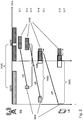
- FIG. 1 schematically shows a user equipment UE operating with a base station BS being part of a cellular network CN.
- the base station BS is in particular configured to comply with the cellular wireless communication standards of 2G, 3G, 4G, 5G and/or beyond.
- the user equipment UE is camping on the base station. It is a reduced-capability user equipment, which means it is not capable to process the full supported downlink frequency band SDFB and/or the supported uplink frequency band SUFB of the base station BS.
- reduced-capability devices are called NR light or NR-REDCAP. This implies that the reduced-capability user equipment is expected to operate in full duplex, regardless of the reduced-capability qualification. This makes this deployment different to e.g. NB-IoT, where no duplex signalling is possible.
- the base station BS is aware of the capable frequency bandwidth CBW of the user equipment UE, which preferably was exchanged during the initial process of camping on the base station as part of the capability information.
- the horizontal axis depicts the frequency where the deployment of the base stations BS supported frequency bands SDFB and SUFB are shown. Here it is shown a frequency division duplex (FDD) deployment, that means the supported uplink and the downlink frequency bands are separated.
- FDD frequency division duplex
- This separation is not arbitrary, but in a predetermined fixed distance depicting the nominal spacing NMS.
- This fixed nominal spacing NMS is preferably derived from the respective implemented technology standard, like for LTE 3GPP TS 36.101.
- the base station BS For serving a reduced-capability user equipment UE the base station BS is carrying out the following steps, shown in vertical order, indicating the time. That means, what is in the same height, it is supposed to happen more or less in parallel.
- step S1 the base station BS considers in a certain range, which can be decoded by the camping at least one reduced-capability user equipment - therefore complying with the capable frequency bandwidth CBW of the user equipment - that said at least one user equipment will monitor signals dedicated for said user equipment.
- this - at least for LTE deployment - is deployed in close proximity to the master information block MIB, which needs to be read by any camping user equipment anyway, at least for receiving always up to date system information and any other broadcasted information.
- the base station BS sends for an imminent data transmission session a first downlink signal for said user equipment UE indicating an uplink assignment UA for a scheduled uplink frequency band SUB.
- a first downlink signal for said user equipment UE indicating an uplink assignment UA for a scheduled uplink frequency band SUB.
- Such data transmission are expected to happen in parallel to a downlink data transmission from the base station BS, which the user equipment UE is expected to monitor.
- step S2 both scheduled frequency bands in the uplink and the downlink direction are deployed and supposed to be monitored by the user equipment in the downlink and used for data transmission in the uplink.
- At least one indication is transmitted by the base station as indicated in step S3.
- another uplink assignment UA is signalled to the user equipment UE within the scheduled downlink frequency band SDB.
- the uplink assignment UA for step S4 shows a scheduled uplink frequency band SUB in a completely different area of the supported uplink frequency band SUFB.
- FIG. 2 it is shown a second example of the invention applied in a similar way as before.
- Steps S11-S14 more or less correspond to the steps S1-S4 of Fig. 1 .
- a scheduled uplink frequency band SUB comparably close to the edge of the supported uplink frequency band of the base station. Due to the total size of the frequency bandwidth it fully fits into the supported uplink frequency band.
- the corresponding parallel scheduled downlink frequency band SDB is larger in size than the scheduled uplink frequency band SUB. This leads due to the fixed distance of the nominal spacing NMS, that as shown in step S14 parts of the scheduled downlink frequency band SDB protrude the edge of the supported downlink frequency band SDFB.
- step S15 the scheduled downlink frequency band SDB is shifted to the edge of the supported downlink frequency band SDFB. This assures that the whole scheduled downlink frequency band may be used in that step, in order to assure the possible data throughput, if needed.
- step S17 this is mitigated by shifting again the resulting scheduled downlink frequency band SDB to the edge of the supported downlink frequency band SDFB.
- This exemplifying embodiment shows, that it is reliably assured that the scheduling in up- and downlink direction is fully usable for the user equipment UE.
- FIG. 3 shows a sequence diagram indicating the signalled messages between user equipment UE and base station BS in an exemplifying embodiment of the invention.
- the sequence starts with message M1, in particular in course with the procedures carried out for camping on the base station, wherein the user equipment sends capability information to the base station.
- the base station issues a UE capability request to the user equipment.
- Said capability request is issued by the cellular network if user equipment capabilities have not been forwarded by the previous serving base stations.
- the user equipment sends its capabilities as part of the network registration procedure to the base station.
- LTE in general user equipment's capabilities are maintained in the MME, i.e. being part of the NAS procedure TS23.401 and carried out via RRC procedures TS36.331 e.g. If the user equipment has changed its E-UTRAN radio access capabilities, it shall request higher layers to initiate the necessary NAS procedures (see TS 23.401) that would result in the update of user equipment's radio access capabilities using a new RRC connection.
- method for NR exists involving TS 38.331, TS.23.401 and the communication is done by means of the AMF (Access and Mobility Management Function).
- the user equipment submits with the UE capability message M1 its capabilities to the base station.
- the UE capability message M1 comprises all information relating to UE capabilities. This relates in particular to all capable frequency bands of the user equipment, both in the uplink and the downlink.
- the base station BS sends with message M2 a first downlink signal to the user equipment.
- the user equipment knows which frequency range to monitor for such downlink signal message from the base station based on previously acknowledged or defined information, e.g. in proximity to the master information block MIB.
- Part of the downlink signal M2 is an uplink assignment UA. Based on the uplink assignment UA the user equipment knows where in the supported uplink frequency range of base station BS it may carry out uplink transmission.
- no uplink transmission are due, therefore no signals/messages are sent from the user equipment to the base station.
- the base station needs to carry out parallel downlink transmissions to the user equipment. These need to be scheduled and the user equipment UE needs to know where these downlink transmissions are scheduled.
- the user equipment UE can easily derive the center of the scheduled downlink frequency band SDB. For that the user equipment UE applies the entire capable frequency bandwidth CBW. However due to other distribution rules only a part of the scheduled downlink frequency bandwidth SDB may be used for scheduling indication by the base station BS, and hence the user equipment UE only listens to that fraction of its capable frequency band CBW.
- Such measures are e.g. in LTE known where all camping user equipments UE are distributed over the capable supported frequency range, so that each user equipment listens equally often to each frequency range, and each frequency range is equally often used for scheduling for all user equipments UE.
- the user equipment UE is prepared to monitor the data transmissions of the base station BS within the scheduled downlink frequency band SDB with message M3, until data dedicated for the user equipment are submitted.
- the user equipment UE carries out said monitoring and decodes signals or data packets dedicated for the user equipment UE.
Landscapes
- Engineering & Computer Science (AREA)
- Signal Processing (AREA)
- Computer Networks & Wireless Communication (AREA)
- Quality & Reliability (AREA)
- Mobile Radio Communication Systems (AREA)
Priority Applications (6)
| Application Number | Priority Date | Filing Date | Title |
|---|---|---|---|
| EP20167592.3A EP3890230A1 (fr) | 2020-04-01 | 2020-04-01 | Procédé de planification améliorée de ressources de réseau pour des équipements utilisateur à capacité réduite |
| JP2022559936A JP7423817B2 (ja) | 2020-04-01 | 2021-03-29 | 低能力ユーザ装置のためにネットワークリソースのスケジューリングを向上させる方法 |
| EP21715256.0A EP4128626B1 (fr) | 2020-04-01 | 2021-03-29 | Procédé de planification améliorée de ressources de réseau pour des équipements utilisateur à capacité réduite |
| CN202180039183.6A CN115606146B (zh) | 2020-04-01 | 2021-03-29 | 用于降低能力的用户设备的网络资源的增强调度的方法 |
| US17/912,895 US20230145892A1 (en) | 2020-04-01 | 2021-03-29 | Method for enhanced scheduling of network resources for reduced capability user equipments |
| PCT/EP2021/058159 WO2021198181A1 (fr) | 2020-04-01 | 2021-03-29 | Procédé pour améliorer la planification de ressources de réseau pour équipements utilisateurs à capacité réduite |
Applications Claiming Priority (1)
| Application Number | Priority Date | Filing Date | Title |
|---|---|---|---|
| EP20167592.3A EP3890230A1 (fr) | 2020-04-01 | 2020-04-01 | Procédé de planification améliorée de ressources de réseau pour des équipements utilisateur à capacité réduite |
Publications (1)
| Publication Number | Publication Date |
|---|---|
| EP3890230A1 true EP3890230A1 (fr) | 2021-10-06 |
Family
ID=70154321
Family Applications (2)
| Application Number | Title | Priority Date | Filing Date |
|---|---|---|---|
| EP20167592.3A Withdrawn EP3890230A1 (fr) | 2020-04-01 | 2020-04-01 | Procédé de planification améliorée de ressources de réseau pour des équipements utilisateur à capacité réduite |
| EP21715256.0A Active EP4128626B1 (fr) | 2020-04-01 | 2021-03-29 | Procédé de planification améliorée de ressources de réseau pour des équipements utilisateur à capacité réduite |
Family Applications After (1)
| Application Number | Title | Priority Date | Filing Date |
|---|---|---|---|
| EP21715256.0A Active EP4128626B1 (fr) | 2020-04-01 | 2021-03-29 | Procédé de planification améliorée de ressources de réseau pour des équipements utilisateur à capacité réduite |
Country Status (5)
| Country | Link |
|---|---|
| US (1) | US20230145892A1 (fr) |
| EP (2) | EP3890230A1 (fr) |
| JP (1) | JP7423817B2 (fr) |
| CN (1) | CN115606146B (fr) |
| WO (1) | WO2021198181A1 (fr) |
Cited By (1)
| Publication number | Priority date | Publication date | Assignee | Title |
|---|---|---|---|---|
| WO2023197188A1 (fr) * | 2022-04-12 | 2023-10-19 | 北京小米移动软件有限公司 | Procédé et appareil de transmission d'informations et dispositif de communication et support de stockage |
Citations (2)
| Publication number | Priority date | Publication date | Assignee | Title |
|---|---|---|---|---|
| US20160323885A1 (en) * | 2015-02-02 | 2016-11-03 | Telefonaktiebolaget Lm Ericsson (Publ) | Method and Apparatus for Transmitting and Receiving Signals in a Frequency Band |
| EP3244553A1 (fr) * | 2015-01-09 | 2017-11-15 | Samsung Electronics Co., Ltd. | Procédé et appareil de transmission d'un canal de commande pour un terminal dans un système de communication sans fil |
Family Cites Families (3)
| Publication number | Priority date | Publication date | Assignee | Title |
|---|---|---|---|---|
| GB2510138A (en) * | 2013-01-24 | 2014-07-30 | Sony Corp | Allocating communications resources within different frequency ranges according to the relative capability of a communications device |
| JP6545809B2 (ja) * | 2015-02-05 | 2019-07-17 | テレフオンアクチーボラゲット エルエム エリクソン(パブル) | 適応型周波数分離に基づく測定手順 |
| US10506596B2 (en) * | 2016-10-28 | 2019-12-10 | Qualcomm Incorporated | Coexistence of interleaved and contiguous uplink transmissions |
-
2020
- 2020-04-01 EP EP20167592.3A patent/EP3890230A1/fr not_active Withdrawn
-
2021
- 2021-03-29 CN CN202180039183.6A patent/CN115606146B/zh active Active
- 2021-03-29 EP EP21715256.0A patent/EP4128626B1/fr active Active
- 2021-03-29 US US17/912,895 patent/US20230145892A1/en active Pending
- 2021-03-29 WO PCT/EP2021/058159 patent/WO2021198181A1/fr not_active Ceased
- 2021-03-29 JP JP2022559936A patent/JP7423817B2/ja active Active
Patent Citations (2)
| Publication number | Priority date | Publication date | Assignee | Title |
|---|---|---|---|---|
| EP3244553A1 (fr) * | 2015-01-09 | 2017-11-15 | Samsung Electronics Co., Ltd. | Procédé et appareil de transmission d'un canal de commande pour un terminal dans un système de communication sans fil |
| US20160323885A1 (en) * | 2015-02-02 | 2016-11-03 | Telefonaktiebolaget Lm Ericsson (Publ) | Method and Apparatus for Transmitting and Receiving Signals in a Frequency Band |
Non-Patent Citations (1)
| Title |
|---|
| ERICSSON: "New SID on support of reduced capability NR devices", vol. TSG RAN, no. Sitges, Spain; 20191209 - 20191212, 12 December 2019 (2019-12-12), XP051840369, Retrieved from the Internet <URL:https://ftp.3gpp.org/tsg_ran/TSG_RAN/TSGR_86/Docs/RP-193238.zip RP-193238 New SID on support of reduced capability NR devices .doc> [retrieved on 20191212] * |
Cited By (1)
| Publication number | Priority date | Publication date | Assignee | Title |
|---|---|---|---|---|
| WO2023197188A1 (fr) * | 2022-04-12 | 2023-10-19 | 北京小米移动软件有限公司 | Procédé et appareil de transmission d'informations et dispositif de communication et support de stockage |
Also Published As
| Publication number | Publication date |
|---|---|
| JP2023521009A (ja) | 2023-05-23 |
| CN115606146A (zh) | 2023-01-13 |
| JP7423817B2 (ja) | 2024-01-29 |
| CN115606146B (zh) | 2025-09-02 |
| EP4128626A1 (fr) | 2023-02-08 |
| EP4128626C0 (fr) | 2025-10-08 |
| WO2021198181A1 (fr) | 2021-10-07 |
| EP4128626B1 (fr) | 2025-10-08 |
| US20230145892A1 (en) | 2023-05-11 |
Similar Documents
| Publication | Publication Date | Title |
|---|---|---|
| US11751277B2 (en) | Method and apparatus for selecting Bandwidth part (BWP) for subsequent transmission in pre-configured resources based Small Data Transmission (SDT) in a wireless communication system | |
| US10750534B2 (en) | Method and apparatus to receive and transmit data in a mobile communication system | |
| US11316562B2 (en) | Method and apparatus to activate and deactivate CSI reporting on PUCCH in a mobile communication system | |
| JP6797120B2 (ja) | 端末装置、基地局装置、方法および電気回路 | |
| JP6797121B2 (ja) | 端末装置、基地局装置、方法および電気回路 | |
| JP6661608B2 (ja) | 端末装置、基地局装置、通信方法および集積回路 | |
| JP6640077B2 (ja) | 端末装置、および通信方法 | |
| US20150049705A1 (en) | Coexistence interference reporting mechanism | |
| US10873982B2 (en) | Terminal apparatus, control method, and integrated circuit | |
| CN111096055A (zh) | 终端设备、基站设备、方法和记录介质 | |
| TW202041056A (zh) | 通訊裝置及通訊方法 | |
| JP2014510462A (ja) | 搬送波集積技術を使用する無線通信システムにおける副搬送波の不活性化方法及び装置 | |
| JP2018085545A (ja) | 端末装置、基地局装置、通信システム、通信方法および集積回路 | |
| JP2016508687A (ja) | 無線通信システムにおける端末の通信方法及び装置 | |
| US10742387B2 (en) | Terminal apparatus, base station apparatus, communication method, and integrated circuit | |
| US20190053208A1 (en) | Information transmission method and system, and device | |
| US20190132809A1 (en) | Terminal apparatus, communication method, and integrated circuit | |
| EP4128626B1 (fr) | Procédé de planification améliorée de ressources de réseau pour des équipements utilisateur à capacité réduite | |
| JP2017038117A (ja) | 端末装置、基地局装置、通信システム、通知方法および集積回路 | |
| US11057851B2 (en) | Terminal apparatus, communication method, and integrated circuit | |
| JP2014236366A (ja) | 端末装置、基地局装置、通信システム、通信方法および集積回路 | |
| JPWO2017163784A1 (ja) | 無線基地局及び通信制御方法 | |
| JP2014220667A (ja) | 端末装置、基地局装置、通信システム、通信方法および集積回路 |
Legal Events
| Date | Code | Title | Description |
|---|---|---|---|
| PUAI | Public reference made under article 153(3) epc to a published international application that has entered the european phase |
Free format text: ORIGINAL CODE: 0009012 |
|
| STAA | Information on the status of an ep patent application or granted ep patent |
Free format text: STATUS: THE APPLICATION HAS BEEN PUBLISHED |
|
| AK | Designated contracting states |
Kind code of ref document: A1 Designated state(s): AL AT BE BG CH CY CZ DE DK EE ES FI FR GB GR HR HU IE IS IT LI LT LU LV MC MK MT NL NO PL PT RO RS SE SI SK SM TR |
|
| STAA | Information on the status of an ep patent application or granted ep patent |
Free format text: STATUS: THE APPLICATION IS DEEMED TO BE WITHDRAWN |
|
| 18D | Application deemed to be withdrawn |
Effective date: 20220407 |