EP3890246B1 - Verfahren und vorrichtung zur rückkopplung von csi-messungen und speichermedium - Google Patents
Verfahren und vorrichtung zur rückkopplung von csi-messungen und speichermedium Download PDFInfo
- Publication number
- EP3890246B1 EP3890246B1 EP18941509.4A EP18941509A EP3890246B1 EP 3890246 B1 EP3890246 B1 EP 3890246B1 EP 18941509 A EP18941509 A EP 18941509A EP 3890246 B1 EP3890246 B1 EP 3890246B1
- Authority
- EP
- European Patent Office
- Prior art keywords
- csi measurement
- configuration information
- reference signal
- feedback
- csi
- Prior art date
- Legal status (The legal status is an assumption and is not a legal conclusion. Google has not performed a legal analysis and makes no representation as to the accuracy of the status listed.)
- Active
Links
Images


Classifications
-
- H—ELECTRICITY
- H04—ELECTRIC COMMUNICATION TECHNIQUE
- H04W—WIRELESS COMMUNICATION NETWORKS
- H04W72/00—Local resource management
- H04W72/02—Selection of wireless resources by user or terminal
-
- H—ELECTRICITY
- H04—ELECTRIC COMMUNICATION TECHNIQUE
- H04W—WIRELESS COMMUNICATION NETWORKS
- H04W72/00—Local resource management
- H04W72/20—Control channels or signalling for resource management
-
- H—ELECTRICITY
- H04—ELECTRIC COMMUNICATION TECHNIQUE
- H04B—TRANSMISSION
- H04B7/00—Radio transmission systems, i.e. using radiation field
- H04B7/02—Diversity systems; Multi-antenna system, i.e. transmission or reception using multiple antennas
- H04B7/04—Diversity systems; Multi-antenna system, i.e. transmission or reception using multiple antennas using two or more spaced independent antennas
- H04B7/06—Diversity systems; Multi-antenna system, i.e. transmission or reception using multiple antennas using two or more spaced independent antennas at the transmitting station
- H04B7/0613—Diversity systems; Multi-antenna system, i.e. transmission or reception using multiple antennas using two or more spaced independent antennas at the transmitting station using simultaneous transmission
- H04B7/0615—Diversity systems; Multi-antenna system, i.e. transmission or reception using multiple antennas using two or more spaced independent antennas at the transmitting station using simultaneous transmission of weighted versions of same signal
- H04B7/0619—Diversity systems; Multi-antenna system, i.e. transmission or reception using multiple antennas using two or more spaced independent antennas at the transmitting station using simultaneous transmission of weighted versions of same signal using feedback from receiving side
- H04B7/0621—Feedback content
- H04B7/0626—Channel coefficients, e.g. channel state information [CSI]
-
- H—ELECTRICITY
- H04—ELECTRIC COMMUNICATION TECHNIQUE
- H04B—TRANSMISSION
- H04B7/00—Radio transmission systems, i.e. using radiation field
- H04B7/02—Diversity systems; Multi-antenna system, i.e. transmission or reception using multiple antennas
- H04B7/04—Diversity systems; Multi-antenna system, i.e. transmission or reception using multiple antennas using two or more spaced independent antennas
- H04B7/06—Diversity systems; Multi-antenna system, i.e. transmission or reception using multiple antennas using two or more spaced independent antennas at the transmitting station
- H04B7/0613—Diversity systems; Multi-antenna system, i.e. transmission or reception using multiple antennas using two or more spaced independent antennas at the transmitting station using simultaneous transmission
- H04B7/0615—Diversity systems; Multi-antenna system, i.e. transmission or reception using multiple antennas using two or more spaced independent antennas at the transmitting station using simultaneous transmission of weighted versions of same signal
- H04B7/0619—Diversity systems; Multi-antenna system, i.e. transmission or reception using multiple antennas using two or more spaced independent antennas at the transmitting station using simultaneous transmission of weighted versions of same signal using feedback from receiving side
- H04B7/0621—Feedback content
- H04B7/063—Parameters other than those covered in groups H04B7/0623 - H04B7/0634, e.g. channel matrix rank or transmit mode selection
-
- H—ELECTRICITY
- H04—ELECTRIC COMMUNICATION TECHNIQUE
- H04B—TRANSMISSION
- H04B7/00—Radio transmission systems, i.e. using radiation field
- H04B7/02—Diversity systems; Multi-antenna system, i.e. transmission or reception using multiple antennas
- H04B7/04—Diversity systems; Multi-antenna system, i.e. transmission or reception using multiple antennas using two or more spaced independent antennas
- H04B7/06—Diversity systems; Multi-antenna system, i.e. transmission or reception using multiple antennas using two or more spaced independent antennas at the transmitting station
- H04B7/0613—Diversity systems; Multi-antenna system, i.e. transmission or reception using multiple antennas using two or more spaced independent antennas at the transmitting station using simultaneous transmission
- H04B7/0615—Diversity systems; Multi-antenna system, i.e. transmission or reception using multiple antennas using two or more spaced independent antennas at the transmitting station using simultaneous transmission of weighted versions of same signal
- H04B7/0619—Diversity systems; Multi-antenna system, i.e. transmission or reception using multiple antennas using two or more spaced independent antennas at the transmitting station using simultaneous transmission of weighted versions of same signal using feedback from receiving side
- H04B7/0621—Feedback content
- H04B7/0632—Channel quality parameters, e.g. channel quality indicator [CQI]
-
- H—ELECTRICITY
- H04—ELECTRIC COMMUNICATION TECHNIQUE
- H04B—TRANSMISSION
- H04B7/00—Radio transmission systems, i.e. using radiation field
- H04B7/02—Diversity systems; Multi-antenna system, i.e. transmission or reception using multiple antennas
- H04B7/04—Diversity systems; Multi-antenna system, i.e. transmission or reception using multiple antennas using two or more spaced independent antennas
- H04B7/06—Diversity systems; Multi-antenna system, i.e. transmission or reception using multiple antennas using two or more spaced independent antennas at the transmitting station
- H04B7/0613—Diversity systems; Multi-antenna system, i.e. transmission or reception using multiple antennas using two or more spaced independent antennas at the transmitting station using simultaneous transmission
- H04B7/0615—Diversity systems; Multi-antenna system, i.e. transmission or reception using multiple antennas using two or more spaced independent antennas at the transmitting station using simultaneous transmission of weighted versions of same signal
- H04B7/0619—Diversity systems; Multi-antenna system, i.e. transmission or reception using multiple antennas using two or more spaced independent antennas at the transmitting station using simultaneous transmission of weighted versions of same signal using feedback from receiving side
- H04B7/0636—Feedback format
- H04B7/0639—Using selective indices, e.g. of a codebook, e.g. pre-distortion matrix index [PMI] or for beam selection
-
- H—ELECTRICITY
- H04—ELECTRIC COMMUNICATION TECHNIQUE
- H04L—TRANSMISSION OF DIGITAL INFORMATION, e.g. TELEGRAPHIC COMMUNICATION
- H04L5/00—Arrangements affording multiple use of the transmission path
- H04L5/0001—Arrangements for dividing the transmission path
- H04L5/0014—Three-dimensional division
- H04L5/0023—Time-frequency-space
-
- H—ELECTRICITY
- H04—ELECTRIC COMMUNICATION TECHNIQUE
- H04L—TRANSMISSION OF DIGITAL INFORMATION, e.g. TELEGRAPHIC COMMUNICATION
- H04L5/00—Arrangements affording multiple use of the transmission path
- H04L5/003—Arrangements for allocating sub-channels of the transmission path
- H04L5/0048—Allocation of pilot signals, i.e. of signals known to the receiver
-
- H—ELECTRICITY
- H04—ELECTRIC COMMUNICATION TECHNIQUE
- H04L—TRANSMISSION OF DIGITAL INFORMATION, e.g. TELEGRAPHIC COMMUNICATION
- H04L5/00—Arrangements affording multiple use of the transmission path
- H04L5/003—Arrangements for allocating sub-channels of the transmission path
- H04L5/0048—Allocation of pilot signals, i.e. of signals known to the receiver
- H04L5/005—Allocation of pilot signals, i.e. of signals known to the receiver of common pilots, i.e. pilots destined for multiple users or terminals
-
- H—ELECTRICITY
- H04—ELECTRIC COMMUNICATION TECHNIQUE
- H04L—TRANSMISSION OF DIGITAL INFORMATION, e.g. TELEGRAPHIC COMMUNICATION
- H04L5/00—Arrangements affording multiple use of the transmission path
- H04L5/003—Arrangements for allocating sub-channels of the transmission path
- H04L5/0053—Allocation of signalling, i.e. of overhead other than pilot signals
-
- H—ELECTRICITY
- H04—ELECTRIC COMMUNICATION TECHNIQUE
- H04L—TRANSMISSION OF DIGITAL INFORMATION, e.g. TELEGRAPHIC COMMUNICATION
- H04L5/00—Arrangements affording multiple use of the transmission path
- H04L5/003—Arrangements for allocating sub-channels of the transmission path
- H04L5/0053—Allocation of signalling, i.e. of overhead other than pilot signals
- H04L5/0055—Physical resource allocation for ACK/NACK
-
- H—ELECTRICITY
- H04—ELECTRIC COMMUNICATION TECHNIQUE
- H04L—TRANSMISSION OF DIGITAL INFORMATION, e.g. TELEGRAPHIC COMMUNICATION
- H04L5/00—Arrangements affording multiple use of the transmission path
- H04L5/003—Arrangements for allocating sub-channels of the transmission path
- H04L5/0053—Allocation of signalling, i.e. of overhead other than pilot signals
- H04L5/0057—Physical resource allocation for CQI
-
- H—ELECTRICITY
- H04—ELECTRIC COMMUNICATION TECHNIQUE
- H04L—TRANSMISSION OF DIGITAL INFORMATION, e.g. TELEGRAPHIC COMMUNICATION
- H04L5/00—Arrangements affording multiple use of the transmission path
- H04L5/0091—Signalling for the administration of the divided path, e.g. signalling of configuration information
- H04L5/0094—Indication of how sub-channels of the path are allocated
-
- H—ELECTRICITY
- H04—ELECTRIC COMMUNICATION TECHNIQUE
- H04W—WIRELESS COMMUNICATION NETWORKS
- H04W72/00—Local resource management
- H04W72/04—Wireless resource allocation
- H04W72/044—Wireless resource allocation based on the type of the allocated resource
- H04W72/0446—Resources in time domain, e.g. slots or frames
-
- H—ELECTRICITY
- H04—ELECTRIC COMMUNICATION TECHNIQUE
- H04W—WIRELESS COMMUNICATION NETWORKS
- H04W72/00—Local resource management
- H04W72/04—Wireless resource allocation
- H04W72/044—Wireless resource allocation based on the type of the allocated resource
- H04W72/0453—Resources in frequency domain, e.g. a carrier in FDMA
-
- H—ELECTRICITY
- H04—ELECTRIC COMMUNICATION TECHNIQUE
- H04W—WIRELESS COMMUNICATION NETWORKS
- H04W72/00—Local resource management
- H04W72/20—Control channels or signalling for resource management
- H04W72/23—Control channels or signalling for resource management in the downlink direction of a wireless link, i.e. towards a terminal
-
- H—ELECTRICITY
- H04—ELECTRIC COMMUNICATION TECHNIQUE
- H04W—WIRELESS COMMUNICATION NETWORKS
- H04W72/00—Local resource management
- H04W72/50—Allocation or scheduling criteria for wireless resources
- H04W72/54—Allocation or scheduling criteria for wireless resources based on quality criteria
- H04W72/542—Allocation or scheduling criteria for wireless resources based on quality criteria using measured or perceived quality
-
- H—ELECTRICITY
- H04—ELECTRIC COMMUNICATION TECHNIQUE
- H04L—TRANSMISSION OF DIGITAL INFORMATION, e.g. TELEGRAPHIC COMMUNICATION
- H04L5/00—Arrangements affording multiple use of the transmission path
- H04L5/003—Arrangements for allocating sub-channels of the transmission path
- H04L5/0048—Allocation of pilot signals, i.e. of signals known to the receiver
- H04L5/0051—Allocation of pilot signals, i.e. of signals known to the receiver of dedicated pilots, i.e. pilots destined for a single user or terminal
Definitions
- the present disclosure relates to a field of communication technology, and particularly to a method and an apparatus for CSI (Channel State Information) measurement feedback in a V2X (Vehicle to Everything) direct communication scenario and a storage medium.
- CSI Channel State Information
- an on-board device may perform direct communication with other devices (such as other on-board devices, roadside infrastructure, and the like) can through the sidelink.
- Direct communication has characteristics of short delay and low overhead.
- the direct communication scenario in LTE (Long Term Evolution) V2X technology does not support unicast and multicast communication, but only supports broadcast communication. Since it is broadcast communication, before the transmitting device transmits information to the receiving device in direct communication with the transmitting device, the receiving device does not need to measure and feedback the CSI.
- LTE Long Term Evolution
- CN108282212A provides a method for processing channel state information.
- the method comprises the following steps: receiving configuration information for channel state informationmeasurement from wireless network equipment by user equipment, wherein the configuration information comprises information of a resource for the channel state information measurement and measurement attribute information for indicating the resource, and the measurement attribute comprises channel measurement, or X types of interference measurements, or the channel measurement and X types of interference measurements, wherein X is an integer greater than or equal to 1; and performing channel state information measurement by the user equipment according to the configuration information and feeding back the channel state information.
- the configuration information comprises information of a resource for the channel state information measurement and measurement attribute information for indicating the resource
- the measurement attribute comprises channel measurement, or X types of interference measurements, or the channel measurement and X types of interference measurements, wherein X is an integer greater than or equal to 1
- X is an integer greater than or equal to 1
- WO2016/022841A1 determines device-to-device (D2D) transmission parameters for signal transmission over a D2D communication link between a first user equipment (UE) device and a second UE device.
- the eNB instructs the first UE device to transmit a reference signal that is received by the second UE device.
- the second UE device reports D2D channel characteristic information indicative of the received reference signal.
- the base station determines the D2D transmission parameters and provides the parameters to the first UE device.
- Embodiments of the present disclosure provide a method and an apparatus for CSI measurement feedback in a V2X direct communication scenario and a storage medium.
- the base station configures the CSI measurement reference signal resource set for the first device in the V2X direct communication, and the first device transmits CSI measurement configuration information to the second device performing direct communication with the first device, so that the second device transmits the CSI measurement feedback information to the first device after the second device performs CSI measurement according to the CSI measurement configuration information.
- a method for CSI measurement feedback is provided, so that a more suitable MCS can be selected for information transmission and the spectrum efficiency is improved.
- the network architecture and business scenario in embodiments of the present disclosure is to explain the technical solutions of embodiments of the present disclosure more clearly, and does not constitute a limit to the technical solutions provided by the embodiments of the present disclosure.
- Those of ordinary skill in the art will know that with the evolution of network architecture and the emergence of new business scenarios, the technical solutions provided in the embodiments of the present disclosure are equally applicable to similar technical problems.
- FIG 1 is a schematic diagram of a network architecture, which is applied to embodiments not forming part of the present disclosure.
- the network architecture may be a network architecture of a C-V2X system.
- C refers to Cellular
- the C-V2X system is an on-board wireless communication system based on the evolution of cellular network communication systems such as 3G, 4G, or 5G
- the network architecture may include: a core network 11, an access network 12, a terminal 13, and a vehicle 14.
- the core network 11 includes several core network devices.
- the function of the core network device is mainly to provide user connections, manage users and complete bearing of services, and provide an interface to the external network as the bearer network.
- the core network of the LTE (Long Term Evolution) system may include MME (Mobility Management Entity), S-GW (Serving Gateway), and P-GW (PDN Gateway) and other devices.
- the core network of the 5G NR system may include AMF (Access and Mobility Management Function) entities, UPF (User Plane Function) entities and SMF (Session Management Function) entities and other devices.
- AMF Access and Mobility Management Function
- UPF User Plane Function
- SMF Session Management Function
- the access network 12 includes several access network devices 120.
- the access network device 120 and the core network device 110 communicate with each other through a certain air interface technology, such as the S1 interface in the LTE system, and the NG interface in the 5G NR system.
- the access network device 120 may be a BS (Base Station), which is an apparatus employed in the access network and configured to provide wireless communication function to the terminal.
- the base station may include various forms of macro evolved NodeB, micro evolved NodeB, relay stations, access points and the like.
- the names of devices with base station functions may be different.
- the device is called eNodeB or eNB
- 5G NR systems the device is called gNodeB or gNB.
- the name of "base station” may change.
- the above apparatuses that provides wireless communication for the terminal are collectively called access network devices.
- the terminal 13 may include various devices with wireless communication functions, such as on-board devices, wearable devices, computing device or other processing devices connected to a wireless modem, as well as various forms of User Equipment (UE), Mobile Station (MS), terminal device, etc. For the sake of easy description, the above devices are collectively called terminals.
- the access network device 120 and the terminal 13 communicate through some kind of the air interface technologies, such as Uu interface.
- the vehicle 14 may be an autonomous vehicle or a non-autonomous vehicle.
- the vehicle 14 is equipped with an on-board device, and the vehicle 14 realizes communication with other vehicles, terminal 13 and other devices, such as RSU (Road Side Unit), through the on-board device.
- the on-board device may also be called an on-board terminal, an on-board communication apparatus, or other names, which is not limited in the embodiments of the present disclosure.
- the on-board device may be an apparatus integrated in the on-board T-BOX (Telematics BOX), or it may be an apparatus separate from the vehicle body.
- the on-board device may be installed in the vehicle 14 before the vehicle 14 leaves the factory, or may be installed in the vehicle 14 after the vehicle 14 leaves the factory.
- the on-board device of the vehicle 14 and other devices can communicate with each other through a direct communication interface (such as a PC5 interface). Accordingly, the communication link established based on the direct communication interface may be called a direct link or a sidelink.
- the access network 12 and the core network 11 may be used for transfer, that is, the communication link between the terminal 13 and the access network device 120 in the original cellular network is used for communication.
- the communication based on the direct communication interface has the characteristics of short delay and low overhead, which is suitable for communication between on-board device and other peripheral devices that are in geographical proximity.
- the above network architecture illustrated in FIG 1 may implement V2X business scenarios.
- the above network architecture may also include devices such as RSUs, V2X application servers, and V2X control function nodes, which are not limited in embodiments of the present disclosure.
- the technical solutions described in embodiments of the present disclosure may be applied to the 5G NR system, and may also be applicable to subsequent evolution systems of the 5G NR system.
- a method for CSI measurement feedback is provided for the direct communication scenario in the above V2X business scenario, so that a more appropriate MCS (Modulation and Coding Scheme) can be selected for information transmission and the spectrum efficiency is improved.
- MCS Modulation and Coding Scheme
- the first device and the second device are devices at both ends of the direct communication in the V2X business scenario, and the sidelink may be established by the first device and the second device through a direct communication interface (such as a PC5 interface).
- the sidelink is used for interaction of user data and control signaling.
- the first device may be an on-board device of the vehicle 14 in the network architecture illustrated in FIG 1
- the second device may be an on-board device of another vehicle, or a terminal 13 or an RSU.
- the first device may be the terminal 13 in the network architecture illustrated in FIG 1
- the second device may be other terminals, and may also be an on-board device of the vehicle 14 or an RSU.
- the same device for the same device (for example, the same on-board device or the same terminal), it may be used as the first device in some scenarios, and may also be used as the second device in other scenarios.
- FIG 2 is a flow chart illustrating a method for CSI measurement feedback in a V2X direct communication scenario according to an embodiment. This method is applied to the network architecture illustrated in FIG 1 . This method includes the following steps (201-203).
- a first device receives CSI measurement reference signal resource pool configuration information transmitted by a base station.
- the base station predefines the resource pool of the CSI measurement reference signal resource set, and transmits the CSI measurement reference signal resource set to the device performing V2X direct communication through the CSI measurement reference signal resource pool configuration information.
- the CSI measurement reference signal resource set includes n CSI measurement reference signal resources, in which n is a positive integer.
- the CSI measurement reference signal resource pool configuration information includes identification information of n CSI measurement reference signal resources in the CSI measurement reference signal resource set.
- the identification information of the CSI measurement reference signal resource is configured to uniquely indicate the CSI measurement reference signal resource, and different CSI measurement reference signal resources have different identification information.
- the CSI measurement reference signal resources refer to reference signal resources used to measure CSI.
- the CSI measurement reference signal resource set includes at least one of the following CSI measurement reference signal resources: a sidelink NZP CSI-RS (sidelink Non Zero Power Channel State Information-Reference Signal) resource, a sidelink ZP CSI-RS (sidelink Zero Power Channel State Information-Reference Signal) resource, a sidelink DRS (sidelink Discovery Reference Signal) resource, a sidelink SSB (Sidelink Synchronization Signal Block) resource, and a sidelink DMRS (sidelink Demodulation Reference Signal).
- the above sidelink DRS resource includes at least one sidelink PSS (sidelink Primary Synchronized Signal), at least one sidelink SSS (sidelink Secondary Synchronized Signal), and at least one sidelink PBCH (sidelink Physical Broadcast Channel).
- the above sidelink SSB resource may also include at least one sidelink PSS, at least one sidelink SSS, and at least one sidelink PBCH.
- SSB may be called SS/PBCH Block.
- the "sidelink” described in the disclosure may also be referred to as "V2X".
- the sidelink added before by a certain object means that the object is an object used for a sidelink or a V2X.
- the sidelink NZP CSI-RS resource indicates the NZP CSI-RS resource used for a sidelink or a V2X.
- the sidelink SSB resource represents an SSB resource used for a sidelink or a V2X.
- the resource pool of the CSI measurement reference signal resource set is similar to the resource pool of the PSSCH (Physical Sidelink Share Channel), of the PSCCH (Physical Sidelink Control Channel), of the PSDCH (Physical Sidelink Discovery Channel) or of the sidelink DMRS, and the resource pool of the CSI measurement reference signal resource set may or may not overlap with the other resource pools mentioned above, which is not limited in embodiments of the present disclosure.
- the CSI measurement reference signal resource pool configuration information further includes at least one of a subcarrier spacing, a cyclic prefix (CP), a frequency domain position, a time domain position, a Port, and a Quasi co-location indication corresponding to the CSI measurement reference signal resource.
- the frequency domain position corresponding to the CSI measurement reference signal resource refers to the frequency domain position occupied by the CSI measurement reference signal resource.
- a size and position of a section of bandwidth may be provided, and RB (Resource Block)/RBs, RE (Resource Element)/REs or subcarrier/subcarriers which occupied the bandwidth is/are provided.
- the time domain position corresponding to the CSI measurement reference signal resource refers to the time domain position occupied by the CSI measurement reference signal resource, including period, offset, slot, mini-slot, symbol and other time-domain location information.
- the port corresponding to the CSI measurement reference signal resource refers to the antenna port through which the transmitter transmits the CSI measurement reference signal resource.
- the CSI measurement reference signal resource pool configuration information includes the port configuration corresponding to the CSI measurement reference signal resource, considering that the capabilities of respective transmitters are different, a lower configuration may be included.
- the transmitter can dynamically indicate the receiver, for example, by using SCI (Sidelink Control Information) signaling in the PSCCH.
- the Quasi co-location indicator corresponding to the CSI measurement reference signal resource is used to indicate that a receiving beam same as the measurement reference signal in the indicator needs to be used for reception and measurement when measuring the CSI on the resource.
- the indicator may include sidelink RS ID of type D.
- the first device transmits CSI measurement configuration information to a second device in direct communication with the first device.
- the first device may select m CSI measurement reference signal resources from the n CSI measurement reference signal resources included in the resource set for the second device in direct communication with the first device to perform CSI measurement, in which m is a positive integer less than or equal to n.
- the first device transmits the CSI measurement configuration information to the second device through the PSCCH.
- the first device transmits a first SCI signaling to the second device through the PSCCH, in which the first SCI signaling includes the CSI measurement configuration information.
- the first SCI signaling further includes identification information of the transmitter (that is, the first device) and/or identification information of the receiver (that is, the second device).
- the CSI measurement configuration information includes identification information of m CSI measurement reference signal resources in n CSI measurement reference signal resources.
- the CSI measurement configuration information further includes at least one of the following information: a subcarrier spacing, a cyclic prefix (CP), a frequency domain position, a time domain position, a Port, and a Quasi co-location indication corresponding to the CSI measurement reference signal resource.
- CP cyclic prefix
- the format of a SCI signaling used to transmit the CSI measurement configuration information may be distinguished from the format of a SCI signaling used to indicate the resource used for data transmission.
- step 203 the second device transmits CSI measurement feedback information to the first device according to the CSI measurement configuration information.
- the second device performs CSI measurement according to the CSI measurement configuration information, and then transmits the measurement result to the first device through the CSI measurement feedback information.
- the first device receives the CSI measurement feedback information transmitted by the second device.
- the CSI measurement feedback information includes at least one of the following: a CQI (Channel Quality Indicator), a PMI (Precoding Matrix Indicator), a RI (Rank Indication), a L1-RSRP (Layer 1-Reference Signal Received Power), a L1-SINR (Layer 1-Signal to Interference and Noise Ratio), and the identification information of the measured CSI measurement reference signal resources.
- a CQI Channel Quality Indicator
- PMI Precoding Matrix Indicator
- RI Rank Indication
- L1-RSRP Layer 1-Reference Signal Received Power
- L1-SINR Layer 1-Signal to Interference and Noise Ratio
- the CSI measurement feedback information may include at least one of CQI, PMI, and RI, and Alternatively or additionally, further includes the identification information of the measured CSI measurement reference signal resource, such as sidelink NZP CSI-RS ID, sidelink ZP CSI-RS ID, sidelink DRS ID, sidelink SSB ID, or sidelink DMRS ID.
- the CSI measurement feedback information may include the L1-RSRP and/or the L1-RSRP, and may further include the identification information of the measured CSI measurement reference signal resource, such as sidelink NZP CSI-RS ID, sidelink ZP CSI-RS ID, sidelink DRS ID, sidelink SSB ID, or sidelink DMRS ID.
- the second device may transmit the CSI measurement feedback information to the first device through PSFCH (Physical Sidelink Feedback Channel), and may also transmit the CSI measurement feedback information to the first device through PSSCH.
- PSFCH Physical Sidelink Feedback Channel
- the second device transmits a second SCI signaling to the first device, in which the second SCI signaling includes the CSI measurement feedback information.
- the second SCI signaling further includes identification information of the transmitter (that is, the second device) and/or identification information of the receiver (that is, the first device).
- the base station configures the CSI measurement reference signal resource set for the first device in the V2X direct communication, and the first device transmits CSI measurement configuration information to the second device in direct communication with the first device, so that the second device transmits the CSI measurement feedback information to the first device after the second device performs CSI measurement according to the CSI measurement configuration information.
- a method for CSI measurement feedback is provided, so that a more suitable MCS can be selected for information transmission and the spectrum efficiency is improved.
- FIG 3 is a flow chart illustrating a method for CSI measurement feedback in a V2X direct communication scenario according to another embodiment. This method is applied to the network architecture illustrated in FIG. 1 . This method includes the following steps (301-303).
- a first device receives CSI measurement reference signal resource pool configuration information and feedback mechanism configuration information transmitted by a base station.
- the base station further predefines multiple CSI measurement feedback mechanisms, and transmits the multiple CSI measurement feedback mechanisms to the device performing V2X direct communication through the feedback mechanism configuration information.
- the base station may transmit the CSI measurement reference signal resource pool configuration information and the feedback mechanism configuration information to the first device through system information.
- the CSI measurement reference signal resource pool configuration information and the feedback mechanism configuration information may be transmitted in the same piece of system information, or may be transmitted in two different pieces of system information, which is not limited in embodiments of the present disclosure.
- the feedback mechanism configuration information includes configuration information of k types of CSI measurement feedback mechanisms, in which k is a positive integer.
- the CSI measurement feedback mechanism is configured to indicate the manner for performing CSI measurement and feedback.
- the above k types of CSI measurement feedback mechanisms include at least one of the following: a periodic measurement feedback mechanism, an aperiodic measurement feedback mechanism, and a semi-static measurement feedback mechanism.
- the periodic measurement feedback mechanism refers to periodically perform CSI measurement and feedback.
- the aperiodic measurement feedback mechanism refers to non-periodically perform CSI measurement and feedback. For example, a certain device performs one CSI measurement and feedback after receiving the CSI feedback trigger signaling transmitted by another device.
- the semi-static measurement feedback mechanism refers to that a certain device starts to perform CSI measurement and feedback after receiving the CSI feedback trigger signaling transmitted by another device, and stops performing the CSI measurement and feedback when the measurement reaches a certain number of times or when it receives a stop feedback trigger signaling transmitted by another device.
- the configuration information of the CSI measurement feedback mechanism includes at least one of the following: time domain configuration information, frequency domain configuration information, and feedback content configuration information.
- the time domain configuration information is configured to indicate a time when the CSI measurement feedback information is transmitted.
- its time domain configuration information may include period, start time offset, frame, subframe, slot, mini-slot, symbol and other information.
- the time domain configuration information may include the feedback time.
- the specific feedback time may be indicated by frame, subframe, slot, mini-slot, symbol and other information, or an offset is provided, and the feedback time is the offset plus the time of the CSI feedback trigger signaling.
- its time-domain configuration information may include the start feedback time and period, and Alternatively or additionally also include the stop feedback time or the feedback duration, in which the start feedback time and the stop feedback time may be indicated clearly by the frame, subframe, slot, mini-slot, symbol and other information, and the feedback duration may indicate the number of time units (such as frame, subframe, slot, mini-slot, symbol) in which feedback is performed.
- the time for the first feedback of the CSI measurement feedback information may also be calculated by adding a time interval to the transmitting time of the CSI feedback trigger signaling.
- the time interval may be predefined in the standard or protocol, or pre-configured by the base station, or transmitted by the first device to the second device, which is not limited in embodiments of the present disclosure.
- the CSI feedback trigger signaling is transmitted from the transmitter to the receiver, and is a signaling for instructing the receiver to perform CSI measurement and feedback.
- the CSI feedback trigger signaling may be a SCI signaling.
- the stop feedback time or the feedback duration described above may be carried in the configuration information of the CSI measurement feedback mechanism and transmitted through another separate signaling, which is not limited in embodiments of the present disclosure.
- the frequency domain configuration information is configured to indicate frequency domain resources used for transmitting the CSI measurement feedback information. Since the CSI measurement feedback information may be transmitted through PSFCH or PSSCH, the frequency domain resource may be a frequency domain resource allocated for the PSFCH or PSSCH.
- the feedback content configuration information is configured to indicate content included in the CSI measurement feedback information.
- the CSI measurement feedback information includes at least one of the following contents: CQI, PMI, RI, L1-RSRP, L1-SINR, and the identification information of the measured CSI measurement reference signal resource.
- the first device transmits CSI measurement configuration information and CSI measurement feedback mechanism to the second device in direct communication with the first device.
- the first device in addition to transmitting the CSI measurement configuration information to the second device, the first device also transmits the CSI measurement feedback mechanism to the second device.
- the first device may select one CSI measurement feedback mechanism from k types of CSI measurement feedback mechanisms configured by the base station, and notify the second device of the selected CSI measurement feedback mechanism and its configuration information.
- step 303 the second device transmits CSI measurement feedback information to the first device according to the CSI measurement configuration information and the CSI measurement feedback mechanism.
- the second device determines on which CSI measurement reference signal resource/resources CSI measurement is performed. Moreover, according to the CSI measurement feedback mechanism, the second device determines the manner for performing CSI measurement and feedback, and obtains the measurement result by performing the CSI measurement according to the manner mentioned above and transmits the measurement result to the first device through the CSI measurement feedback information.
- the second device obtaining the CSI measurement feedback mechanism from the first device is only taken as an example for introduction and description.
- the second device may also obtain the CSI measurement feedback mechanism from the base station.
- the second device receives the feedback mechanism configuration information transmitted by the base station, and determines the CSI measurement feedback mechanism adopted when performing the CSI measurement feedback to the first device based on the information mentioned above.
- multiple CSI measurement feedback mechanisms are predefined, so that devices in V2X direct communication can select an appropriate CSI measurement feedback mechanism for CSI measurement and feedback according to actual needs.
- the technical solution of the present disclosure is introduced only from the perspective of the interaction between the first device and the second device.
- the above steps related to the first device may be implemented separately as the CSI measurement feedback method in the V2X direct communication scenario on the first device side, and the above steps related to the second device can be separately implemented as the CSI measurement feedback method in the V2X direct communication scenario on the second device side.
- FIG 4 is a block diagram illustrating an apparatus for CSI measurement feedback in a V2X direct communication scenario according to an embodiment.
- the apparatus has the function of realizing the above method embodiments on the first device side, and the function may be realized by hardware, or by hardware executing corresponding software.
- the apparatus 400 conclude a configuration information receiving module 410, a configuration information transmitting module 420 and a feedback information receiving module 430.
- the configuration information receiving module 410 is configured to receive CSI measurement reference signal resource pool configuration information transmitted by a base station, in which the CSI measurement reference signal resource pool configuration information includes identification information of n CSI measurement reference signal resources in a CSI measurement reference signal resource set, in which n is a positive integer.
- the configuration information transmitting module 420 is configured to transmit CSI measurement configuration information to a second device in direct communication with the first device, in which the CSI measurement configuration information includes the identification information of m CSI measurement reference signal resources in the n CSI measurement reference signal resources, in which m is a positive integer less than or equal to n.
- the feedback information receiving module 430 is configured to receive CSI measurement feedback information transmitted by the second device.
- the base station configures the CSI measurement reference signal resource set for the first device in the V2X direct communication, and the first device transmits CSI measurement configuration information to the second device in direct communication with the first device, so that the second device transmits the CSI measurement feedback information to the first device after the second device performs CSI measurement according to the CSI measurement configuration information.
- a method for CSI measurement feedback is provided, so that a more suitable MCS can be selected for information transmission and the spectrum efficiency is improved.
- the CSI measurement reference signal resource set includes at least one of the following CSI measurement reference signal resources: a sidelink NZP CSI-RS resource, a sidelink ZP CSI-RS resource, a sidelink DRS resource, a sidelink SSB resource, or a sidelink DMRS resource.
- the CSI measurement reference signal resource pool configuration information further includes at least one of the following: a subcarrier spacing, a cyclic prefix (CP), a frequency domain position, a time domain position, a Port, or a Quasi co-location indication corresponding to the CSI measurement reference signal resource.
- the configuration information receiving module 410 is further configured to receive feedback mechanism configuration information transmitted by the base station, in which the feedback mechanism configuration information includes configuration information of k types of CSI measurement feedback mechanisms, in which k is a positive integer; and the configuration information transmitting module 420 is further configured to transmit the CSI measurement feedback mechanism to the second device.
- the k types of CSI measurement feedback mechanisms include at least one of the following: a periodic measurement feedback mechanism, an aperiodic measurement feedback mechanism, and a semi-static measurement feedback mechanism.
- the configuration information of the CSI measurement feedback mechanism includes at least one of the following: time domain configuration information, frequency domain configuration information, and feedback content configuration information; in which the time domain configuration information is configured to indicate a time of transmitting the CSI measurement feedback information, the frequency domain configuration information is configured to indicate frequency domain resources for transmitting the CSI measurement feedback information, and the feedback content configuration information is configured to indicate the content included in the CSI measurement feedback information.
- the feedback information receiving module 430 is configured to: receive the CSI measurement feedback information transmitted by the second device through PSFCH; or, receive the CSI measurement feedback information transmitted by the second device through PSSCH.
- the CSI measurement feedback information includes at least one of the following: a CQI, a PMI, a RI, a L1-RSRP, a L1-SINR, and the identification information of the measured CSI measurement reference signal resource.
- FIG 5 is a block diagram illustrating an apparatus for CSI measurement feedback in a V2X direct communication scenario according to another embodiment.
- the apparatus has the function of realizing the above method embodiments on the second device side, and the function may be realized by hardware, or by hardware executing corresponding software.
- the apparatus 500 include a configuration information receiving module 510 and a feedback information transmitting module 520.
- the configuration information receiving module 510 is configured to receive CSI measurement configuration information transmitted by a first device in direct communication with the second device, in which the CSI measurement configuration information includes identification information of m CSI measurement reference signals in a CSI measurement reference signal resource set configured by a base station, in which m is a positive integer.
- the feedback information transmitting module 520 is configured to transmit CSI measurement feedback information to the first device according to the CSI measurement configuration information.
- the base station configures the CSI measurement reference signal resource set for the first device in the V2X direct communication, and the first device transmits CSI measurement configuration information to the second device in direct communication with the first device, so that the second device transmits the CSI measurement feedback information to the first device after the second device performs CSI measurement according to the CSI measurement configuration information.
- a method for CSI measurement feedback is provided, so that a more suitable MCS can be selected for information transmission and the spectrum efficiency is improved.
- the configuration information receiving module 510 is further configured to receive a CSI measurement feedback mechanism transmitted by the first device or the base station; and the feedback information transmitting module 520 is further configured to transmit the CSI measurement feedback information to the first device according to the CSI measurement configuration information and the CSI measurement feedback mechanism.
- the division of the above functional modules is used only as an example.
- the above functions can be allocated to different functional modules according to actual needs. That is, the content structure of the device is divided into different functional modules to complete all or part of the functions described above.
- An apparatus for CSI measurement feedback in a V2X direct communication scenario is also provided in an embodiment of the present disclosure, which can implement the method for CSI measurement feedback in the V2X direct communication scenario in the present disclosure.
- the apparatus may be the first network device introduced in the above disclosure, and may also be set in the first device.
- the apparatus includes a processor, and a memory configured to store instructions executable by the processor.
- the processor is configured to: receive CSI measurement reference signal resource pool configuration information transmitted by a base station, in which the CSI measurement reference signal resource pool configuration information includes identification information of n CSI measurement reference signal resources in a CSI measurement reference signal resource set, in which n is a positive integer; transmit CSI measurement configuration information to a second device in direct communication with the first device, in which the CSI measurement configuration information includes the identification information of m CSI measurement reference signal resources in the n CSI measurement reference signal resources, in which m is a positive integer less than or equal to n; and receive the CSI measurement feedback information transmitted by the second device.
- the CSI measurement reference signal resource set includes at least one of the following CSI measurement reference signal resources: a sidelink NZP CSI-RS resource, a sidelink ZP CSI-RS resource, a sidelink DRS resource, a sidelink SSB resource, or a sidelink DMRS resource.
- the CSI measurement reference signal resource pool configuration information further includes at least one of the following: a subcarrier spacing, a cyclic prefix (CP), a frequency domain position, a time domain position, a Port, and a Quasi co-location indication corresponding to the CSI measurement reference signal resource.
- the processor is further configured to: receive feedback mechanism configuration information transmitted by the base station, in which the feedback mechanism configuration information includes configuration information of k types of CSI measurement feedback mechanisms, in which k is a positive integer; and transmit the CSI measurement feedback mechanism to the second device.
- the k types of CSI measurement feedback mechanisms include at least one of the following: a periodic measurement feedback mechanism, an aperiodic measurement feedback mechanism, and a semi-static measurement feedback mechanism.
- the configuration information of the CSI measurement feedback mechanism includes at least one of the following: time domain configuration information, frequency domain configuration information, and feedback content configuration information; in which the time domain configuration information is configured to indicate a time of transmitting the CSI measurement feedback information, the frequency domain configuration information is configured to indicate frequency domain resources for transmitting the CSI measurement feedback information, and the feedback content configuration information is configured to indicate the content included in the CSI measurement feedback information.
- the processor is configured to: receive the CSI measurement feedback information transmitted by the second device through PSFCH; or, receive the CSI measurement feedback information transmitted by the second device through PSSCH.
- the CSI measurement feedback information includes at least one of the following: a CQI, a PMI, a RI, a L1-RSRP, a L1-SINR, and the identification information of the measured CSI measurement reference signal resource.
- An apparatus for CSI measurement feedback in a V2X direct communication scenario is also provided in an embodiment of the present disclosure, which can implement the method for CSI measurement feedback in the V2X direct communication scenario in the present disclosure.
- the apparatus may be the second network device introduced in the above disclosure, and may also be set in the second device.
- the apparatus includes a processor, and a memory configured to store instructions executable by the processor.
- the processor is configured to: receive CSI measurement configuration information transmitted by a first device in direct communication with the second device, in which the CSI measurement configuration information includes identification information of m CSI measurement reference signals in a CSI measurement reference signal resource set configured by a base station, in which m is a positive integer; and transmit CSI measurement feedback information to the first device according to the CSI measurement configuration information.
- the processor is further configured to: receive a CSI measurement feedback mechanism transmitted by the first device or the base station; and transmit the CSI measurement feedback information to the first device according to the CSI measurement configuration information and the CSI measurement feedback mechanism.
- the device includes hardware structures and /or software modules corresponding to execute specific functions with the aim to realize the above functions.
- the embodiments may be realized by hardware or the combination of hardware and computer software. Whether some function is executed by hardware or driving hardware by computer software depends on specific application and design constraints of the technical method. Those skilled in the art may use different methods for respective specific applications to realize the described functions, but such realization should not be considered as going beyond the scope of the technical solutions of the embodiments of the present disclosure.
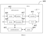
- FIG 6 is a schematic diagram illustrating a device 600 in a V2X direct communication scenario according to an embodiment not forming part of the present invention.
- the device 600 may be a device for direct communication with other devices in a V2X business scenario, such as on-board devices, terminals and other electronic devices.
- the device 600 may be a first device or a second device described above.
- the device 600 includes a transmitter 601, a receiver 602 and a processor 603.
- the processor 603 may be a controller, which is represented as a "controller/processor 603" in FIG 6 .
- the device 600 may further include a modem processor 605, in which the modem processor 605 may include an encoder 606, a modulator 607, a decoder 608, and a demodulator 609.
- the transmitter 601 adjusts (e.g. performs analog conversion, filter, amplification, and up conversion on) the output samples and generates an uplink signal, which is transmitted to the access network device via an antenna.
- the antenna receives the downlink signal transmitted by the access network device.
- the receiver 602 adjusts (e.g. performs filter, amplification, down conversion, digitization on) the signal received from the antenna and provides input samples.
- the encoder 606 receives business data and signaling messages to be transmitted on the uplink, and processes (e.g. formats, encodes, and interleaves) the business data and signaling messages.
- the modulator 607 further processes (e.g.
- the demodulator 609 processes (e.g. demodulates) the input samples and provides symbol estimation.
- the decoder 608 processes (e.g. deinterleaves and decodes) the symbol estimation and provides decoded data and signaling messages transmitted to the device 600.
- the encoder 606, the modulator 607, the demodulator 609, and the decoder 608 may be realized by a synthesized modem processor 605. These units are processed according to the wireless access technology adopted by the wireless access network (for example, the access technology of LTE and other evolved systems). It should be noted that when the device 600 does not include the modem processor 605, the above functions of the modem processor 605 may also be realized by the processor 603.
- the processor 603 controls and manages the actions of the device 600, and is used to execute the process performed by the device 600 in the above embodiments of the present disclosure.
- the processor 603 is further configured to execute each step of the transmitting device or the receiving device in the above method embodiments, and/or other steps of the technical solutions described in the embodiments of the present disclosure.
- the device 600 may further include a memory 604, in which the memory 604 is configured to store program codes and data for the device 600.
- FIG 6 only illustrates a simplified design of the device 600.
- the device 600 may include any number of transmitters, receivers, processors, modem processors, memories, and the like, and all devices that can implement the embodiments of the present disclosure are within the protection scope of the embodiments of the present disclosure.
- a non-transitory computer-readable storage medium with computer programs stored on is provided in embodiments of the present disclosure.
- the computer programs are executed by the device 600, the method for CSI measurement feedback in the V2X direct communication scenario is implemented as described before.
Landscapes
- Engineering & Computer Science (AREA)
- Signal Processing (AREA)
- Computer Networks & Wireless Communication (AREA)
- Quality & Reliability (AREA)
- Physics & Mathematics (AREA)
- Mathematical Physics (AREA)
- Mobile Radio Communication Systems (AREA)
Claims (15)
- Ein Verfahren zur Kanalzustandsinformations (CSI) -Messrückmeldung in einem V2X-Direktkommunikationsszenario, dadurch gekennzeichnet, dass das Verfahren umfasst:Empfangen (201) durch eine erste Vorrichtung von Konfigurationsinformationen über einen CSI-Mess-Referenzsignal-Ressourcenpool, gesendet von einer Basisstation, wobei die Konfigurationsinformationen über den CSI-Mess-Referenzsignal-Ressourcenpool Identifikationsinformationen von n CSI-Mess-Referenzsignal-Ressourcen in einem Satz von CSI-Mess-Referenzsignal-Ressourcen umfassen, wobei n eine positive ganze Zahl ist;Senden (202) durch die erste Vorrichtung von CSI-Messkonfigurationsinformationen an eine zweite Vorrichtung, die sich in Direktkommunikation mit der ersten Vorrichtung befindet, wobei die CSI-Messkonfigurationsinformationen die Identifikationsinformationen von m CSI-Mess-Referenzsignal-Ressourcen in den n CSI-Mess-Referenzsignal-Ressourcen umfassen, wobei m eine positive ganze Zahl ist, die kleiner oder gleich n ist; undEmpfangen (203) durch die erste Vorrichtung von CSI-Messrückmeldeinformationen, gesendet von der zweiten Vorrichtung.
- Das Verfahren nach Anspruch 1, wobei der Satz von CSI-Mess-Referenzsignal-Ressourcen mindestens eine der folgenden CSI-Mess-Referenzsignal-Ressourcen umfasst: eine Sidelink-Non-Zero-Power-CSI-Referenzsignal (NZP CSI-RS)-Ressource, eine Sidelink-Zero-Power-CSI-Referenzsignal (ZP CSI-RS)-Ressource, eine Sidelink-Discovery-Referenzsignal (DRS)-Ressource, einen Sidelink-Synchronisierungssignalblock (SSB) und eine Sidelink-Demodulationsreferenzsignal (DMRS)-Ressource.
- Das Verfahren nach Anspruch 1 oder 2, wobei die Konfigurationsinformationen über den CSI-Mess-Referenzsignal-Ressourcenpool ferner mindestens eine der folgenden Angaben umfassen: eine Unterträgerabstandskonfiguration, ein zyklisches Präfix (CP), eine Frequenzbereichsposition, eine Zeitbereichsposition, einen Port und eine Quasi Co-Location-Indikation, die der CSI-Mess-Referenzsignal-Ressource zugeordnet ist.
- Das Verfahren nach einem der Ansprüche 1-3, ferner umfassend:Empfangen durch die erste Vorrichtung von Konfigurationsinformationen über einen Rückmeldemechanismus, gesendet von der Basisstation, wobei die Konfigurationsinformationen über den Rückmeldemechanismus Konfigurationsinformationen über k Arten von CSI-Messrückmeldemechanismen umfassen, wobei k eine positive ganze Zahl ist; undSenden durch die erste Vorrichtung des CSI-Messrückmeldemechanismus an die zweite Vorrichtung.
- Das Verfahren nach Anspruch 4, wobei die k Arten von CSI-Messrückmeldemechanismen mindestens eine der folgenden Mechanismen umfassen: einen periodischen Messrückmeldemechanismus, einen aperiodischen Messrückmeldemechanismus und einen semistatischen Messrückmeldemechanismus.
- Das Verfahren nach Anspruch 4, wobei die Konfigurationsinformationen über den Rückmeldemechanismus des CSI-Messrückmeldemechanismus mindestens eine der folgenden Informationen umfassen: Zeitbereichskonfigurationsinformationen, Frequenzbereichskonfigurationsinformationen und Rückmeldeinhaltskonfigurationsinformationen;
wobei die Zeitbereichskonfigurationsinformationen dazu eingerichtet sind, eine Zeit für das Senden der CSI-Messrückmeldeinformationen anzuzeigen, die Frequenzbereichskonfigurationsinformationen dazu eingerichtet sind, Frequenzbereichsressourcen für das Senden der CSI-Messrückmeldeinformationen anzuzeigen, und die Rückmeldeinhaltskonfigurationsinformationen dazu eingerichtet sind, den Inhalt anzuzeigen, der in den CSI-Messrückmeldeinformationen enthalten ist. - Das Verfahren nach einem der Ansprüche 1-6, wobei das Empfangen (203) durch die erste Vorrichtung von CSI-Messrückmeldeinformationen, gesendet von der zweiten Vorrichtung, mindestens eine der folgenden Aktionen umfasst:Empfangen durch die erste Vorrichtung der CSI-Messrückmeldeinformationen, gesendet von der zweiten Vorrichtung über einen Physical-Sidelink-Feedback-Kanal (PSFCH); undEmpfangen durch die erste Vorrichtung der CSI-Messrückmeldeinformationen, gesendet von der zweiten Vorrichtung über einen Physical-Sidelink-Shared-Kanal (PSSCH).
- Das Verfahren nach einem der Ansprüche 1-7, wobei die CSI-Messrückmeldeinformationen mindestens eine der folgenden Informationen umfassen: einen Kanalqualitätsindikator (CQI), einen Präcodermatrixindikator (PMI), einen Rangindikator (RI), eine Layer-1-Referenzsignal-Empfangsleistung (L1-RSRP), ein Layer-1-Signal-zu-Interferenz-plus-Rausch-Verhältnis (L1-SINR) und Identifikationsinformationen der gemessenen CSI-Mess-Referenzsignal-Ressource.
- Ein Verfahren zur Kanalzustandsinformations (CSI)-Messrückmeldung in einem V2X-Direktkommunikationsszenario, dadurch gekennzeichnet, dass das Verfahren umfasst:Empfangen (202) durch eine zweite Vorrichtung von CSI-Messkonfigurationsinformationen, gesendet von einer ersten Vorrichtung, die sich in Direktkommunikation mit der zweiten Vorrichtung befindet, wobei die CSI-Messkonfigurationsinformationen Identifikationsinformationen von m CSI-Mess-Referenzsignal-Ressourcen in einem Satz von n CSI-Mess-Referenzsignal-Ressourcen umfassen, der von einer Basisstation konfiguriert wird, wobei m und n positive ganze Zahlen sind und m kleiner oder gleich n ist; undSenden (203) durch die zweite Vorrichtung von CSI-Messrückmeldeinformationen an die erste Vorrichtung gemäß den CSI-Messkonfigurationsinformationen.
- Das Verfahren nach Anspruch 9, ferner umfassend:Empfangen durch die zweite Vorrichtung eines CSI-Messrückmeldemechanismus, gesendet von der ersten Vorrichtung oder von der Basisstation;wobei das Senden durch die zweite Vorrichtung der CSI-Messrückmeldeinformationen an die erste Vorrichtung gemäß den CSI-Messkonfigurationsinformationen umfasst:
Senden durch die zweite Vorrichtung der CSI-Messrückmeldeinformationen an die erste Vorrichtung gemäß den CSI-Messkonfigurationsinformationen und dem CSI-Messrückmeldemechanismus. - Eine Vorrichtung (400) zur Kanalzustandsinformations (CSI)-Messrückmeldung in einem V2X-Direktkommunikationsszenario, angewendet auf eine erste Vorrichtung, dadurch gekennzeichnet, dass die Vorrichtung umfasst:ein Modul (410) zum Empfangen von Konfigurationsinformationen über einen CSI-Mess-Referenzsignal-Ressourcenpool, gesendet von einer Basisstation, wobei die Konfigurationsinformationen über den CSI-Mess-Referenzsignal-Ressourcenpool Identifikationsinformationen von n CSI-Mess-Referenzsignal-Ressourcen in einem Satz von CSI-Mess-Referenzsignal-Ressourcen umfassen, wobei n eine positive ganze Zahl ist;ein Modul (420) zum Senden von CSI-Messkonfigurationsinformationen an eine zweite Vorrichtung, die sich in Direktkommunikation mit der ersten Vorrichtung befindet, wobei die CSI-Messkonfigurationsinformationen die Identifikationsinformationen von m CSI-Mess-Referenzsignal-Ressourcen in den n CSI-Mess-Referenzsignal-Ressourcen umfassen, wobei m eine positive ganze Zahl ist, die kleiner oder gleich n ist; undein Modul (430) zum Empfangen von CSI-Messrückmeldeinformationen, gesendet von der zweiten Vorrichtung.
- Die Vorrichtung nach Anspruch 11, wobei
das Modul zum Empfangen von Konfigurationsinformationen ferner dazu eingerichtet ist, Konfigurationsinformationen über einen Rückmeldemechanismus zu empfangen, gesendet von der Basisstation, wobei die Konfigurationsinformationen über den Rückmeldemechanismus Konfigurationsinformationen über k Arten von CSI-Messrückmeldemechanismen umfassen, wobei k eine positive ganze Zahl ist; und das Modul zum Senden von Konfigurationsinformationen ferner dazu eingerichtet ist, den CSI-Messrückmeldemechanismus an die zweite Vorrichtung zu senden. - Das Verfahren nach Anspruch 11 oder 12, wobei das Modul zum Empfangen von Rückmeldeinformationen dazu eingerichtet ist:die CSI-Messrückmeldeinformationen, gesendet von der zweiten Vorrichtung, über einen Physical-Sidelink-Feedback-Kanal (PSFCH) zu empfangen;
oderdie CSI-Messrückmeldeinformationen, gesendet von der zweiten Vorrichtung, über einen Physical-Sidelink-Shared-Kanal (PSSCH) zu empfangen. - Eine Vorrichtung (500) zur Kanalzustandsinformations (CSI)-Messrückmeldung in einem V2X-Direktkommunikationsszenario, angewendet auf eine zweite Vorrichtung, dadurch gekennzeichnet, dass die Vorrichtung umfasst:ein Modul (510) zum Empfangen von CSI-Messkonfigurationsinformationen, gesendet von einer ersten Vorrichtung, die sich in Direktkommunikation mit der zweiten Vorrichtung befindet, wobei die CSI-Messkonfigurationsinformationen Identifikationsinformationen von m CSI-Mess-Referenzsignal-Ressourcen in einem Satz von n CSI-Mess-Referenzsignal-Ressourcen umfassen, die von einer Basisstation konfiguriert werden, wobei m und n positive ganze Zahlen sind und m kleiner oder gleich n ist; undein Modul (520) zum Senden von CSI-Messrückmeldeinformationen an die erste Vorrichtung gemäß den CSI-Messkonfigurationsinformationen.
- Die Vorrichtung nach Anspruch 14, wobeidas Modul (510) zum Empfangen von Konfigurationsinformationen ferner dazu eingerichtet ist, einen CSI-Messrückmeldemechanismus zu empfangen, gesendet von der ersten Vorrichtung oder von der Basisstation; unddas Modul (520) zum Senden von Rückmeldeinformationen ferner dazu eingerichtet ist, die CSI-Messrückmeldeinformationen an die erste Vorrichtung gemäß den CSI-Messkonfigurationsinformationen und dem CSI-Messrückmeldemechanismus zu senden.
Applications Claiming Priority (1)
| Application Number | Priority Date | Filing Date | Title |
|---|---|---|---|
| PCT/CN2018/118285 WO2020107346A1 (zh) | 2018-11-29 | 2018-11-29 | Csi测量反馈方法、装置及存储介质 |
Publications (3)
| Publication Number | Publication Date |
|---|---|
| EP3890246A1 EP3890246A1 (de) | 2021-10-06 |
| EP3890246A4 EP3890246A4 (de) | 2022-07-13 |
| EP3890246B1 true EP3890246B1 (de) | 2025-06-11 |
Family
ID=66060155
Family Applications (1)
| Application Number | Title | Priority Date | Filing Date |
|---|---|---|---|
| EP18941509.4A Active EP3890246B1 (de) | 2018-11-29 | 2018-11-29 | Verfahren und vorrichtung zur rückkopplung von csi-messungen und speichermedium |
Country Status (5)
| Country | Link |
|---|---|
| US (1) | US20220015067A1 (de) |
| EP (1) | EP3890246B1 (de) |
| CN (2) | CN109644455B (de) |
| ES (1) | ES3037158T3 (de) |
| WO (1) | WO2020107346A1 (de) |
Families Citing this family (76)
| Publication number | Priority date | Publication date | Assignee | Title |
|---|---|---|---|---|
| US11895703B2 (en) * | 2019-01-11 | 2024-02-06 | Lg Electronics Inc. | Method and apparatus for selecting PSSCH resource in NR V2X |
| JP7434331B2 (ja) * | 2019-01-11 | 2024-02-20 | オッポ広東移動通信有限公司 | サイドリンク通信の方法、端末機器及びネットワーク機器 |
| CN111435909B (zh) * | 2019-01-11 | 2022-01-14 | 华为技术有限公司 | 发送和接收反馈信道的方法以及装置 |
| CN121665332A (zh) * | 2019-02-01 | 2026-03-13 | 现代自动车株式会社 | 用于侧链路组播通信的方法和装置 |
| EP3949630A4 (de) * | 2019-04-03 | 2023-05-03 | Fg Innovation Company Limited | Verfahren und vorrichtung zur sidelink-csi-erfassung |
| WO2020220343A1 (en) * | 2019-04-30 | 2020-11-05 | Nec Corporation | Method for communication, communication device, and computer readable medium |
| CN111865483B (zh) * | 2019-04-30 | 2021-09-07 | 华为技术有限公司 | 一种发送、接收csi、配置资源的方法及设备 |
| CN120835411A (zh) * | 2019-04-30 | 2025-10-24 | 中兴通讯股份有限公司 | 无线通信资源配置方法、无线通信装置及存储介质 |
| KR102904014B1 (ko) * | 2019-05-02 | 2025-12-26 | 삼성전자 주식회사 | 무선 통신 시스템에서 채널상태정보 송수신 방법 및 장치 |
| CN118354359A (zh) | 2019-05-02 | 2024-07-16 | 三星电子株式会社 | 用于在侧链路通信中测量和报告信道状态的方法和装置 |
| US12531666B2 (en) | 2019-05-21 | 2026-01-20 | Bunker Hill Technologies Llc | Method and device in nodes used for wireless communication |
| CN111988757B (zh) * | 2019-05-21 | 2021-09-24 | 上海朗帛通信技术有限公司 | 一种被用于无线通信的节点中的方法和装置 |
| CN111988758B (zh) * | 2019-05-22 | 2022-08-19 | 上海朗帛通信技术有限公司 | 一种被用于无线通信的节点中的方法和装置 |
| US12279259B2 (en) | 2019-05-24 | 2025-04-15 | Beijing Xiaomi Mobile Software Co., Ltd. | Feedback information transmission method and apparatus, and device and storage medium |
| EP3994938A4 (de) * | 2019-07-01 | 2023-07-19 | JRD Communication (Shenzhen) Ltd | Kanalzustandsinformationserfassung |
| EP3965353B1 (de) * | 2019-07-10 | 2024-04-10 | LG Electronics Inc. | Verfahren und vorrichtung zur bestimmung der rückkopplungsressource in nr-v2x |
| KR102647853B1 (ko) * | 2019-07-17 | 2024-03-15 | 엘지전자 주식회사 | Nr v2x의 동시 모드에서 채널 측정을 수행하는 방법 및 장치 |
| CN112312453B (zh) * | 2019-07-30 | 2023-02-14 | 华为技术有限公司 | 通信处理方法、通信处理装置以及系统 |
| WO2021023081A1 (en) * | 2019-08-04 | 2021-02-11 | JRD Communication (Shenzhen) Ltd. | Sidelink feedback resource allocation |
| WO2021022551A1 (en) * | 2019-08-08 | 2021-02-11 | Zte Corporation | Feedback channel allocation and transmission method and device |
| CN111836303B (zh) * | 2019-08-08 | 2022-08-02 | 维沃移动通信有限公司 | 一种sidelink测量结果获取方法、发送方法和终端 |
| CN111526494B (zh) * | 2019-08-09 | 2021-08-24 | 维沃移动通信有限公司 | 旁链路资源映射方法、传输方法、网络设备及终端设备 |
| CN110445597B (zh) * | 2019-08-14 | 2022-06-03 | 展讯通信(上海)有限公司 | 反馈资源确定方法及装置 |
| CN110535611B (zh) | 2019-08-14 | 2025-02-11 | 中兴通讯股份有限公司 | 信号发送、接收、信息反馈方法、装置、通信节点及介质 |
| WO2021026894A1 (en) * | 2019-08-15 | 2021-02-18 | Lenovo (Beijing) Limited | Method and apparatus for reporting reference signal receiving power |
| EP4014628A1 (de) * | 2019-08-16 | 2022-06-22 | Qualcomm Incorporated | Auf sidelink basierende kanalzustandsinformationen |
| WO2021034691A1 (en) * | 2019-08-16 | 2021-02-25 | Qualcomm Incorporated | Sidelink-based channel state information |
| WO2021031048A1 (zh) * | 2019-08-16 | 2021-02-25 | 华为技术有限公司 | 一种通信方法及装置 |
| US11418238B2 (en) | 2019-08-16 | 2022-08-16 | Qualcomm Incorporated | Sidelink-based channel state information |
| CN112398554B (zh) * | 2019-08-16 | 2022-06-07 | 华为技术有限公司 | 用于信道测量的方法以及终端装置 |
| WO2021034165A1 (ko) * | 2019-08-22 | 2021-02-25 | 엘지전자 주식회사 | 사이드링크를 지원하는 무선통신시스템에서 단말이 사이드링크 통신을 수행하는 방법 및 이를 위한 장치 |
| US12218875B2 (en) | 2019-08-23 | 2025-02-04 | Lenovo (Beijing) Limited | Apparatus and method of CSI acquisition on sidelink |
| US11870718B2 (en) * | 2019-09-17 | 2024-01-09 | Qualcomm Incorporated | Sidelink CSI report transmission methods and conditions |
| CN112533247B (zh) * | 2019-09-19 | 2022-06-21 | 上海朗帛通信技术有限公司 | 一种被用于无线通信的节点中的方法和装置 |
| EP3799490B1 (de) * | 2019-09-27 | 2022-11-16 | ASUSTek Computer Inc. | Verfahren und vorrichtung zur übertragung von vorrichtung-zu-vorrichtung-kanalmessungen in einem drahtlosen kommunikationssystem |
| WO2021056560A1 (zh) * | 2019-09-29 | 2021-04-01 | 富士通株式会社 | 边链路信息的接收和发送方法以及装置 |
| CN110602776B (zh) * | 2019-09-30 | 2021-10-29 | 展讯通信(上海)有限公司 | 直连链路的参考信号接收功率rsrp测量方法及装置 |
| US11923971B2 (en) * | 2019-10-02 | 2024-03-05 | Qualcomm Incorporated | Modulation and coding scheme table selection for sidelink communications |
| CN115051779A (zh) | 2019-10-12 | 2022-09-13 | 华为技术有限公司 | 通信方法及装置 |
| WO2021072770A1 (zh) * | 2019-10-18 | 2021-04-22 | Oppo广东移动通信有限公司 | 一种侧行反馈方法、设备及存储介质 |
| EP4037199B1 (de) * | 2019-10-22 | 2025-04-30 | LG Electronics Inc. | Verfahren und vorrichtung zur übertragung von informationen über den kanalzustand in nr v2x |
| WO2021077392A1 (en) * | 2019-10-25 | 2021-04-29 | Qualcomm Incorporated | Techniques for determining feedback timing capability in sidelink wireless communications |
| CN114631373B (zh) * | 2019-10-31 | 2025-09-02 | 上海诺基亚贝尔股份有限公司 | 用于侧链路信道的资源映射 |
| CN112769525A (zh) * | 2019-11-06 | 2021-05-07 | 维沃移动通信有限公司 | 旁链路csi上报控制方法、旁链路csi上报方法及相关设备 |
| CN114845278B (zh) * | 2019-11-06 | 2024-10-15 | Oppo广东移动通信有限公司 | 信道质量反馈的方法及装置 |
| CN112788647A (zh) | 2019-11-06 | 2021-05-11 | 维沃移动通信有限公司 | 测量上报的方法、终端设备和网络设备 |
| CN112788620B (zh) * | 2019-11-07 | 2023-06-20 | 华为技术有限公司 | 一种信号处理方法、终端装置、网络装置和通信系统 |
| CN114270925B (zh) | 2019-11-07 | 2024-07-26 | Lg电子株式会社 | 在无线通信系统中取消sl csi报告 |
| CN112788561B (zh) * | 2019-11-08 | 2022-07-12 | 大唐移动通信设备有限公司 | 资源映射方法及终端 |
| US12261791B2 (en) * | 2019-11-20 | 2025-03-25 | Lg Electronics Inc. | Method and device for transmitting reference signal in NR V2X |
| KR102843460B1 (ko) * | 2019-12-06 | 2025-08-08 | 엘지전자 주식회사 | 사이드링크를 지원하는 무선통신시스템에서 단말이 포지셔닝 참조 신호를 송수신하는 방법 및 이를 위한 장치 |
| CN113038416B (zh) | 2019-12-25 | 2023-03-28 | 维沃移动通信有限公司 | 一种信道测量参考信号传输方法及终端 |
| CN113132037A (zh) * | 2020-01-15 | 2021-07-16 | 维沃移动通信有限公司 | 旁链路信息的传输方法和终端设备 |
| ES2983328T3 (es) * | 2020-01-21 | 2024-10-22 | Asustek Comp Inc | Procedimientos y aparatos para manejar informes de información de estado de canal con respecto a la recepción discontinua de enlace lateral en un sistema de comunicación inalámbrica |
| CN114982163B (zh) * | 2020-01-28 | 2024-10-18 | 高通股份有限公司 | 侧链路的干扰测量 |
| CN115024002B (zh) * | 2020-01-30 | 2025-02-21 | Lg电子株式会社 | 无线通信系统中与副链路csi报告相关的ue操作方法 |
| WO2021159468A1 (en) * | 2020-02-14 | 2021-08-19 | Mediatek Singapore Pte. Ltd. | Methods and apparatus of sl l1-rsrp measurement for v2x communication |
| CN115176517B (zh) * | 2020-02-26 | 2026-02-13 | 株式会社Ntt都科摩 | 终端、无线通信方法以及基站 |
| CN115244971A (zh) * | 2020-03-05 | 2022-10-25 | 现代自动车株式会社 | 用于报告侧链路通信的信道状态信息的方法和装置 |
| WO2021207935A1 (en) * | 2020-04-14 | 2021-10-21 | Lenovo (Beijing) Limited | Method and apparatus for beam management on sidelink |
| WO2021226950A1 (en) * | 2020-05-14 | 2021-11-18 | Apple Inc. | Sidelink physical layer procedures |
| CN113676302B (zh) * | 2020-05-15 | 2023-02-21 | 维沃移动通信有限公司 | 信息指示、信息确定方法、装置和通信设备 |
| WO2021232402A1 (en) * | 2020-05-22 | 2021-11-25 | Qualcomm Incorporated | Csi forwarding in sidelink |
| CN115699908A (zh) * | 2020-06-12 | 2023-02-03 | 联想(北京)有限公司 | 用于侧链路drx操作的方法及设备 |
| US20230361955A1 (en) * | 2020-07-22 | 2023-11-09 | Lenovo (Singapore) Pte. Ltd. | Multiple sidelink reference signals |
| WO2022082804A1 (zh) * | 2020-10-23 | 2022-04-28 | 华为技术有限公司 | 测量上报方法及装置 |
| EP4233245A4 (de) * | 2020-10-23 | 2024-11-20 | Qualcomm Incorporated | Meldung der referenzsignalkapazität von kanalzustandsinformationen (csi) für csi-messung mit mehreren sendeempfangspunkten |
| EP4040757B1 (de) * | 2021-02-09 | 2024-07-24 | Telia Company AB | Kommunikationsüberwachung |
| WO2023019466A1 (zh) * | 2021-08-18 | 2023-02-23 | Oppo广东移动通信有限公司 | 无线通信的方法和终端设备 |
| US11805522B2 (en) * | 2021-08-20 | 2023-10-31 | Qualcomm Incorporated | Sidelink feedback techniques in sidelink wireless communications |
| CN115942492A (zh) * | 2021-09-30 | 2023-04-07 | 中兴通讯股份有限公司 | 信息指示、信息接收方法、电子设备和存储介质 |
| CN117412304A (zh) * | 2022-07-15 | 2024-01-16 | 华为技术有限公司 | 一种信号发送方法及装置 |
| CN116326101A (zh) * | 2023-01-18 | 2023-06-23 | 北京小米移动软件有限公司 | 基于侧链路的通信方法、装置及存储介质 |
| US20240250852A1 (en) * | 2023-01-24 | 2024-07-25 | Qualcomm Incorporated | Multi-antenna reader channel state information acquisition |
| WO2025081354A1 (zh) * | 2023-10-17 | 2025-04-24 | 北京小米移动软件有限公司 | 通信方法、终端、网络设备、通信系统及存储介质 |
| CN120433900A (zh) * | 2024-02-02 | 2025-08-05 | 中兴通讯股份有限公司 | 通信方法、装置及存储介质 |
Family Cites Families (26)
| Publication number | Priority date | Publication date | Assignee | Title |
|---|---|---|---|---|
| CN103108405B (zh) * | 2011-11-15 | 2017-09-08 | 中兴通讯股份有限公司 | 无线通信方法和系统 |
| US20130258954A1 (en) * | 2012-03-30 | 2013-10-03 | Sharp Laboratories Of America, Inc. | Devices for selecting a channel state information report |
| US9345039B2 (en) * | 2012-05-31 | 2016-05-17 | Interdigital Patent Holdings, Inc. | Device-to-device (D2D) link adaptation |
| US20150358981A1 (en) * | 2013-01-07 | 2015-12-10 | Lg Electronics Inc. | Method and apparatus for performing device-to-device communication in wireless communication system |
| EP2878157B1 (de) * | 2013-04-24 | 2020-01-01 | Nec Corporation | Verfahren zur verwendung in der d2d-kommunikation und drahtloses kommunikationssystem |
| US10123340B2 (en) * | 2013-05-24 | 2018-11-06 | Lg Electronics Inc. | Method for performing measurement in wireless communication system and apparatus therefor |
| CN106061573B (zh) * | 2014-01-23 | 2019-04-26 | 华为技术有限公司 | 信道状态信息的测量方法及网络节点 |
| US10575291B2 (en) * | 2014-03-21 | 2020-02-25 | Sony Corporation | Telecommunications apparatus and methods |
| US10194452B2 (en) * | 2014-08-08 | 2019-01-29 | Kyocera Corporation | Device-to-device (D2D) channel management with network-assisted reference signal transmission |
| US20180175992A1 (en) * | 2015-06-17 | 2018-06-21 | Telefonaktiebolaget Lm Ericsson (Publ) | A Wireless Device, A Radio Network Node, And Methods Therein |
| WO2017061744A1 (ko) * | 2015-10-04 | 2017-04-13 | 엘지전자 주식회사 | 무선 통신 시스템에서 채널 상태 정보 송수신 방법 및 이를 위한 장치 |
| CN106793092B (zh) * | 2015-11-19 | 2022-07-26 | 中兴通讯股份有限公司 | 控制信道资源的获取方法及设备 |
| CN107294585B (zh) * | 2016-04-01 | 2020-05-12 | 中兴通讯股份有限公司 | 信道状态信息的反馈方法及装置 |
| WO2018030185A1 (ja) * | 2016-08-10 | 2018-02-15 | ソニー株式会社 | 通信装置及び通信方法 |
| CN108282212B (zh) * | 2017-01-06 | 2022-06-14 | 华为技术有限公司 | 一种信道状态信息处理的方法、装置和系统 |
| CN108288989B (zh) * | 2017-01-09 | 2020-12-08 | 华为技术有限公司 | 信道状态信息反馈方法、用户设备及基站 |
| CN108365997B (zh) * | 2017-01-26 | 2021-12-14 | 华为技术有限公司 | 一种信息传输方法和装置 |
| CN108809394A (zh) * | 2017-05-04 | 2018-11-13 | 株式会社Ntt都科摩 | 一种混合信道质量测量方法和用户设备 |
| WO2019036578A1 (en) * | 2017-08-17 | 2019-02-21 | Intel Corporation | Selecting resources for sidelink communication based on geo-location information |
| US10863447B2 (en) * | 2018-07-11 | 2020-12-08 | Samsung Electronics Co., Ltd. | Method and apparatus for multi-antenna transmission in vehicle to vehicle communication |
| CN112567673B (zh) * | 2018-08-09 | 2024-07-26 | 交互数字专利控股公司 | 用于nr v2x的波束赋形和分组 |
| US10979874B2 (en) * | 2018-08-10 | 2021-04-13 | At&T Intellectual Property I, L.P. | Multi-connectivity based vehicle-to-everything communications in a wireless network |
| EP3834438B1 (de) * | 2018-08-30 | 2024-06-19 | Huawei Technologies Co., Ltd. | Techniken für gruppenbasiertes feedback |
| EP3841684B1 (de) * | 2018-09-20 | 2024-04-24 | Huawei Technologies Co., Ltd. | Vorrichtungen zur kommunikation in einem drahtlosen kommunikationsnetz mit strahlformung |
| CN112771962B (zh) * | 2018-09-27 | 2024-10-18 | 交互数字专利控股公司 | 用于nr v2x的基于uu的侧向链路控制 |
| CN111200487B (zh) * | 2018-11-20 | 2021-06-29 | 展讯通信(上海)有限公司 | 混合自动重传请求确认harq-ack的传输方法及装置 |
-
2018
- 2018-11-29 EP EP18941509.4A patent/EP3890246B1/de active Active
- 2018-11-29 WO PCT/CN2018/118285 patent/WO2020107346A1/zh not_active Ceased
- 2018-11-29 US US17/297,413 patent/US20220015067A1/en not_active Abandoned
- 2018-11-29 CN CN201880002214.9A patent/CN109644455B/zh active Active
- 2018-11-29 ES ES18941509T patent/ES3037158T3/es active Active
- 2018-11-29 CN CN202310558687.XA patent/CN116582944A/zh active Pending
Also Published As
| Publication number | Publication date |
|---|---|
| WO2020107346A1 (zh) | 2020-06-04 |
| EP3890246A1 (de) | 2021-10-06 |
| CN116582944A (zh) | 2023-08-11 |
| EP3890246A4 (de) | 2022-07-13 |
| CN109644455A (zh) | 2019-04-16 |
| US20220015067A1 (en) | 2022-01-13 |
| ES3037158T3 (en) | 2025-09-29 |
| CN109644455B (zh) | 2023-07-25 |
Similar Documents
| Publication | Publication Date | Title |
|---|---|---|
| EP3890246B1 (de) | Verfahren und vorrichtung zur rückkopplung von csi-messungen und speichermedium | |
| CN114223174B (zh) | 多trp pdsch传输方案的tbs确定 | |
| US20250300787A1 (en) | Systems and methods of csi reference resource determination | |
| US20210076236A1 (en) | Communication device, communication method, and communication system | |
| CN109845371A (zh) | 下行数据接收方法、发送方法、装置和存储介质 | |
| CN116368884A (zh) | 利用朝向多个trp的时隙内重复的pucch增强的系统和方法 | |
| CN109565360B (zh) | 信息发送方法、接收方法、装置及存储介质 | |
| US20200296699A1 (en) | Wireless communication apparatus, wireless communication method, and computer program | |
| US11991698B2 (en) | Control information sending method, receiving method and apparatus, and storage medium | |
| WO2022236197A1 (en) | Configuring discontinuous reception (drx) parameters for sidelink: communications | |
| CN120937263A (zh) | 用于全双工通信的集中式波束确定 | |
| US12414157B2 (en) | Multiple victim/aggressor collision avoidance | |
| CN108076442B (zh) | 一种pusch传输块长度确定方法及用户设备 | |
| EP3429292B1 (de) | Verfahren und vorrichtung zur downlink-übertragung | |
| WO2024066760A1 (en) | Power resetting for unified transmission configuration indicator | |
| WO2024230331A1 (en) | Unified transmission configuration indicator state indication | |
| WO2024065684A1 (en) | Lag-selective time correlation reporting | |
| CN121002786A (zh) | 物理资源块分配对齐 |
Legal Events
| Date | Code | Title | Description |
|---|---|---|---|
| STAA | Information on the status of an ep patent application or granted ep patent |
Free format text: STATUS: THE INTERNATIONAL PUBLICATION HAS BEEN MADE |
|
| PUAI | Public reference made under article 153(3) epc to a published international application that has entered the european phase |
Free format text: ORIGINAL CODE: 0009012 |
|
| STAA | Information on the status of an ep patent application or granted ep patent |
Free format text: STATUS: REQUEST FOR EXAMINATION WAS MADE |
|
| 17P | Request for examination filed |
Effective date: 20210624 |
|
| AK | Designated contracting states |
Kind code of ref document: A1 Designated state(s): AL AT BE BG CH CY CZ DE DK EE ES FI FR GB GR HR HU IE IS IT LI LT LU LV MC MK MT NL NO PL PT RO RS SE SI SK SM TR |
|
| DAV | Request for validation of the european patent (deleted) | ||
| DAX | Request for extension of the european patent (deleted) | ||
| REG | Reference to a national code |
Free format text: PREVIOUS MAIN CLASS: H04L0012260000 Ref country code: DE Ref legal event code: R079 Ref document number: 602018082601 Country of ref document: DE Ipc: H04L0005000000 |
|
| A4 | Supplementary search report drawn up and despatched |
Effective date: 20220613 |
|
| RIC1 | Information provided on ipc code assigned before grant |
Ipc: H04B 7/06 20060101ALI20220608BHEP Ipc: H04L 5/00 20060101AFI20220608BHEP |
|
| STAA | Information on the status of an ep patent application or granted ep patent |
Free format text: STATUS: EXAMINATION IS IN PROGRESS |
|
| 17Q | First examination report despatched |
Effective date: 20230503 |
|
| GRAP | Despatch of communication of intention to grant a patent |
Free format text: ORIGINAL CODE: EPIDOSNIGR1 |
|
| STAA | Information on the status of an ep patent application or granted ep patent |
Free format text: STATUS: GRANT OF PATENT IS INTENDED |
|
| INTG | Intention to grant announced |
Effective date: 20250207 |
|
| P01 | Opt-out of the competence of the unified patent court (upc) registered |
Free format text: CASE NUMBER: APP_8609/2025 Effective date: 20250220 |
|
| GRAS | Grant fee paid |
Free format text: ORIGINAL CODE: EPIDOSNIGR3 |
|
| GRAA | (expected) grant |
Free format text: ORIGINAL CODE: 0009210 |
|
| STAA | Information on the status of an ep patent application or granted ep patent |
Free format text: STATUS: THE PATENT HAS BEEN GRANTED |
|
| AK | Designated contracting states |
Kind code of ref document: B1 Designated state(s): AL AT BE BG CH CY CZ DE DK EE ES FI FR GB GR HR HU IE IS IT LI LT LU LV MC MK MT NL NO PL PT RO RS SE SI SK SM TR |
|
| REG | Reference to a national code |
Ref country code: GB Ref legal event code: FG4D |
|
| REG | Reference to a national code |
Ref country code: CH Ref legal event code: EP |
|
| REG | Reference to a national code |
Ref country code: DE Ref legal event code: R096 Ref document number: 602018082601 Country of ref document: DE |
|
| REG | Reference to a national code |
Ref country code: IE Ref legal event code: FG4D |
|
| REG | Reference to a national code |
Ref country code: NL Ref legal event code: FP |
|
| REG | Reference to a national code |
Ref country code: ES Ref legal event code: FG2A Ref document number: 3037158 Country of ref document: ES Kind code of ref document: T3 Effective date: 20250929 |
|
| PG25 | Lapsed in a contracting state [announced via postgrant information from national office to epo] |
Ref country code: FI Free format text: LAPSE BECAUSE OF FAILURE TO SUBMIT A TRANSLATION OF THE DESCRIPTION OR TO PAY THE FEE WITHIN THE PRESCRIBED TIME-LIMIT Effective date: 20250611 |
|
| REG | Reference to a national code |
Ref country code: LT Ref legal event code: MG9D |
|
| PG25 | Lapsed in a contracting state [announced via postgrant information from national office to epo] |
Ref country code: NO Free format text: LAPSE BECAUSE OF FAILURE TO SUBMIT A TRANSLATION OF THE DESCRIPTION OR TO PAY THE FEE WITHIN THE PRESCRIBED TIME-LIMIT Effective date: 20250911 Ref country code: GR Free format text: LAPSE BECAUSE OF FAILURE TO SUBMIT A TRANSLATION OF THE DESCRIPTION OR TO PAY THE FEE WITHIN THE PRESCRIBED TIME-LIMIT Effective date: 20250912 |
|
| PG25 | Lapsed in a contracting state [announced via postgrant information from national office to epo] |
Ref country code: BG Free format text: LAPSE BECAUSE OF FAILURE TO SUBMIT A TRANSLATION OF THE DESCRIPTION OR TO PAY THE FEE WITHIN THE PRESCRIBED TIME-LIMIT Effective date: 20250611 |
|
| PG25 | Lapsed in a contracting state [announced via postgrant information from national office to epo] |
Ref country code: HR Free format text: LAPSE BECAUSE OF FAILURE TO SUBMIT A TRANSLATION OF THE DESCRIPTION OR TO PAY THE FEE WITHIN THE PRESCRIBED TIME-LIMIT Effective date: 20250611 |
|
| PG25 | Lapsed in a contracting state [announced via postgrant information from national office to epo] |
Ref country code: RS Free format text: LAPSE BECAUSE OF FAILURE TO SUBMIT A TRANSLATION OF THE DESCRIPTION OR TO PAY THE FEE WITHIN THE PRESCRIBED TIME-LIMIT Effective date: 20250911 |
|
| PG25 | Lapsed in a contracting state [announced via postgrant information from national office to epo] |
Ref country code: LV Free format text: LAPSE BECAUSE OF FAILURE TO SUBMIT A TRANSLATION OF THE DESCRIPTION OR TO PAY THE FEE WITHIN THE PRESCRIBED TIME-LIMIT Effective date: 20250611 |
|
| PG25 | Lapsed in a contracting state [announced via postgrant information from national office to epo] |
Ref country code: PT Free format text: LAPSE BECAUSE OF FAILURE TO SUBMIT A TRANSLATION OF THE DESCRIPTION OR TO PAY THE FEE WITHIN THE PRESCRIBED TIME-LIMIT Effective date: 20251013 |
|
| PGFP | Annual fee paid to national office [announced via postgrant information from national office to epo] |
Ref country code: NL Payment date: 20251119 Year of fee payment: 8 |
|
| REG | Reference to a national code |
Ref country code: AT Ref legal event code: MK05 Ref document number: 1803113 Country of ref document: AT Kind code of ref document: T Effective date: 20250611 |
|
| PG25 | Lapsed in a contracting state [announced via postgrant information from national office to epo] |
Ref country code: IS Free format text: LAPSE BECAUSE OF FAILURE TO SUBMIT A TRANSLATION OF THE DESCRIPTION OR TO PAY THE FEE WITHIN THE PRESCRIBED TIME-LIMIT Effective date: 20251011 |
|
| PGFP | Annual fee paid to national office [announced via postgrant information from national office to epo] |
Ref country code: DE Payment date: 20251119 Year of fee payment: 8 |
|
| PGFP | Annual fee paid to national office [announced via postgrant information from national office to epo] |
Ref country code: GB Payment date: 20251121 Year of fee payment: 8 |
|
| PG25 | Lapsed in a contracting state [announced via postgrant information from national office to epo] |
Ref country code: AT Free format text: LAPSE BECAUSE OF FAILURE TO SUBMIT A TRANSLATION OF THE DESCRIPTION OR TO PAY THE FEE WITHIN THE PRESCRIBED TIME-LIMIT Effective date: 20250611 Ref country code: SM Free format text: LAPSE BECAUSE OF FAILURE TO SUBMIT A TRANSLATION OF THE DESCRIPTION OR TO PAY THE FEE WITHIN THE PRESCRIBED TIME-LIMIT Effective date: 20250611 |
|
| PGFP | Annual fee paid to national office [announced via postgrant information from national office to epo] |
Ref country code: IT Payment date: 20251125 Year of fee payment: 8 |
|
| PGFP | Annual fee paid to national office [announced via postgrant information from national office to epo] |
Ref country code: FR Payment date: 20251126 Year of fee payment: 8 |
|
| PG25 | Lapsed in a contracting state [announced via postgrant information from national office to epo] |
Ref country code: CZ Free format text: LAPSE BECAUSE OF FAILURE TO SUBMIT A TRANSLATION OF THE DESCRIPTION OR TO PAY THE FEE WITHIN THE PRESCRIBED TIME-LIMIT Effective date: 20250611 |
|
| PG25 | Lapsed in a contracting state [announced via postgrant information from national office to epo] |
Ref country code: PL Free format text: LAPSE BECAUSE OF FAILURE TO SUBMIT A TRANSLATION OF THE DESCRIPTION OR TO PAY THE FEE WITHIN THE PRESCRIBED TIME-LIMIT Effective date: 20250611 |
|
| PG25 | Lapsed in a contracting state [announced via postgrant information from national office to epo] |
Ref country code: EE Free format text: LAPSE BECAUSE OF FAILURE TO SUBMIT A TRANSLATION OF THE DESCRIPTION OR TO PAY THE FEE WITHIN THE PRESCRIBED TIME-LIMIT Effective date: 20250611 |
|
| PG25 | Lapsed in a contracting state [announced via postgrant information from national office to epo] |
Ref country code: RO Free format text: LAPSE BECAUSE OF FAILURE TO SUBMIT A TRANSLATION OF THE DESCRIPTION OR TO PAY THE FEE WITHIN THE PRESCRIBED TIME-LIMIT Effective date: 20250611 Ref country code: SK Free format text: LAPSE BECAUSE OF FAILURE TO SUBMIT A TRANSLATION OF THE DESCRIPTION OR TO PAY THE FEE WITHIN THE PRESCRIBED TIME-LIMIT Effective date: 20250611 |
|
| PGFP | Annual fee paid to national office [announced via postgrant information from national office to epo] |
Ref country code: ES Payment date: 20251229 Year of fee payment: 8 |
|
| REG | Reference to a national code |
Ref country code: DE Ref legal event code: R097 Ref document number: 602018082601 Country of ref document: DE |
|
| PG25 | Lapsed in a contracting state [announced via postgrant information from national office to epo] |
Ref country code: DK Free format text: LAPSE BECAUSE OF FAILURE TO SUBMIT A TRANSLATION OF THE DESCRIPTION OR TO PAY THE FEE WITHIN THE PRESCRIBED TIME-LIMIT Effective date: 20250611 |
|
| PLBE | No opposition filed within time limit |
Free format text: ORIGINAL CODE: 0009261 |
|
| STAA | Information on the status of an ep patent application or granted ep patent |
Free format text: STATUS: NO OPPOSITION FILED WITHIN TIME LIMIT |
|
| REG | Reference to a national code |
Ref country code: CH Ref legal event code: L10 Free format text: ST27 STATUS EVENT CODE: U-0-0-L10-L00 (AS PROVIDED BY THE NATIONAL OFFICE) Effective date: 20260423 |