EP3890411A1 - Procédé et appareil de synchronisation temporelle - Google Patents
Procédé et appareil de synchronisation temporelle Download PDFInfo
- Publication number
- EP3890411A1 EP3890411A1 EP19909240.4A EP19909240A EP3890411A1 EP 3890411 A1 EP3890411 A1 EP 3890411A1 EP 19909240 A EP19909240 A EP 19909240A EP 3890411 A1 EP3890411 A1 EP 3890411A1
- Authority
- EP
- European Patent Office
- Prior art keywords
- time information
- time
- sfn
- sib
- information
- Prior art date
- Legal status (The legal status is an assumption and is not a legal conclusion. Google has not performed a legal analysis and makes no representation as to the accuracy of the status listed.)
- Pending
Links
- 238000000034 method Methods 0.000 title claims abstract description 125
- 230000008569 process Effects 0.000 claims abstract description 22
- 230000006870 function Effects 0.000 claims description 45
- 230000011664 signaling Effects 0.000 claims description 28
- 238000012545 processing Methods 0.000 claims description 23
- 102100022734 Acyl carrier protein, mitochondrial Human genes 0.000 claims description 7
- 101000678845 Homo sapiens Acyl carrier protein, mitochondrial Proteins 0.000 claims description 7
- 230000006978 adaptation Effects 0.000 claims description 7
- 238000004590 computer program Methods 0.000 claims description 6
- 108700026140 MAC combination Proteins 0.000 claims 3
- 238000005516 engineering process Methods 0.000 abstract description 7
- 238000004891 communication Methods 0.000 abstract description 5
- 230000000875 corresponding effect Effects 0.000 description 170
- 230000001360 synchronised effect Effects 0.000 description 19
- 238000010586 diagram Methods 0.000 description 15
- 101150096310 SIB1 gene Proteins 0.000 description 5
- CQMJEZQEVXQEJB-UHFFFAOYSA-N 1-hydroxy-1,3-dioxobenziodoxole Chemical compound C1=CC=C2I(O)(=O)OC(=O)C2=C1 CQMJEZQEVXQEJB-UHFFFAOYSA-N 0.000 description 4
- 239000013256 coordination polymer Substances 0.000 description 4
- 230000007774 longterm Effects 0.000 description 4
- 238000013461 design Methods 0.000 description 3
- 230000005540 biological transmission Effects 0.000 description 2
- 230000003068 static effect Effects 0.000 description 2
- 230000009471 action Effects 0.000 description 1
- 230000009286 beneficial effect Effects 0.000 description 1
- 238000011161 development Methods 0.000 description 1
- 230000000694 effects Effects 0.000 description 1
- 230000006872 improvement Effects 0.000 description 1
- 238000012986 modification Methods 0.000 description 1
- 230000004048 modification Effects 0.000 description 1
Images




Classifications
-
- H—ELECTRICITY
- H04—ELECTRIC COMMUNICATION TECHNIQUE
- H04W—WIRELESS COMMUNICATION NETWORKS
- H04W56/00—Synchronisation arrangements
- H04W56/001—Synchronization between nodes
-
- H—ELECTRICITY
- H04—ELECTRIC COMMUNICATION TECHNIQUE
- H04W—WIRELESS COMMUNICATION NETWORKS
- H04W56/00—Synchronisation arrangements
- H04W56/001—Synchronization between nodes
- H04W56/0015—Synchronization between nodes one node acting as a reference for the others
-
- G—PHYSICS
- G01—MEASURING; TESTING
- G01S—RADIO DIRECTION-FINDING; RADIO NAVIGATION; DETERMINING DISTANCE OR VELOCITY BY USE OF RADIO WAVES; LOCATING OR PRESENCE-DETECTING BY USE OF THE REFLECTION OR RERADIATION OF RADIO WAVES; ANALOGOUS ARRANGEMENTS USING OTHER WAVES
- G01S19/00—Satellite radio beacon positioning systems; Determining position, velocity or attitude using signals transmitted by such systems
- G01S19/01—Satellite radio beacon positioning systems transmitting time-stamped messages, e.g. GPS [Global Positioning System], GLONASS [Global Orbiting Navigation Satellite System] or GALILEO
- G01S19/13—Receivers
- G01S19/24—Acquisition or tracking or demodulation of signals transmitted by the system
- G01S19/25—Acquisition or tracking or demodulation of signals transmitted by the system involving aiding data received from a cooperating element, e.g. assisted GPS
- G01S19/256—Acquisition or tracking or demodulation of signals transmitted by the system involving aiding data received from a cooperating element, e.g. assisted GPS relating to timing, e.g. time of week, code phase, timing offset
-
- H—ELECTRICITY
- H04—ELECTRIC COMMUNICATION TECHNIQUE
- H04W—WIRELESS COMMUNICATION NETWORKS
- H04W56/00—Synchronisation arrangements
- H04W56/0055—Synchronisation arrangements determining timing error of reception due to propagation delay
- H04W56/006—Synchronisation arrangements determining timing error of reception due to propagation delay using known positions of transmitter and receiver
Definitions
- Embodiments of this application relate to the field of communication technologies, and in particular, to a time synchronization method and apparatus.
- high-precision time information may be sent to a terminal in a broadcast or unicast manner, to implement time synchronization between terminals.
- a centralized unit Central Unit, CU
- a distributed unit Distributed Unit, DU
- a transmission delay between the CU and the DU is relatively large
- a current technology cannot resolve how to implement time synchronization between terminals when the CU and the DU are separated from each other. Therefore, when the CU and the DU are separated from each other, how to ensure that a network side provides accurate timing for a terminal becomes a problem to be resolved urgently.
- Embodiments of this application provide a time synchronization method and apparatus, so that in a CU-DU split architecture, a DU or a CU is expected to determine high-precision time information, thereby implementing relatively precise time synchronization between terminals.
- a time synchronization method includes: A terminal UE receives a system information block SIB sent by a distributed unit DU, where the SIB is generated by the DU, the SIB includes time information, and the time information indicates a moment corresponding to a boundary of a system frame number SFN at which an end boundary of a system information SI window for sending the SIB is located, or indicates a moment corresponding to a boundary of an SFN immediately after an end boundary of an SI window for sending the SIB.
- the UE processes the time information to obtain a time reference.
- the UE can learn of the moment that is indicated by the time information and that is corresponding to the boundary of the SFN, obtain the time reference based on the time information, and notify an upper layer of the time reference, so that time synchronization can be performed based on the time reference. Therefore, time synchronization between terminals can be implemented in a DU-CU split architecture.
- the SIB further includes the time information and a reference SFN corresponding to the time information
- the time information indicates a moment corresponding to a boundary of the reference SFN.
- the SIB received by the UE may further include the time information and the reference SFN corresponding to the time information, so that the UE can learn of, based on the SIB, the moment that is corresponding to the boundary of the reference SFN and that is indicated by the time information.
- the method further includes: The UE notifies an upper layer of the time reference. Based on this solution, the UE may send a time reference received by the RRC layer to a layer (for example, a NAS layer or an application layer) above an RRC layer, to implement time synchronization.
- a layer for example, a NAS layer or an application layer
- a time synchronization method includes: A distributed unit DU generates a system information block SIB, where the SIB includes time information, and the time information indicates a moment corresponding to a boundary of a system frame number SFN at which an end boundary of a system information SI window for sending the SIB is located, or indicates a moment corresponding to a boundary of an SFN immediately after an end boundary of an SI window for sending the SIB.
- the DU sends the SIB to a terminal UE.
- the DU Based on this solution, the DU generates the SIB including the time information, and sends the SIB to the UE in a broadcast manner, so that the UE learns of the correspondence between the time and the SFN based on the SIB. Therefore, time synchronization between terminals in a cell can be implemented in a DU-CU split architecture.
- the DU may generate the SIB including the time information and the reference SFN corresponding to the time information, where the time information indicates the moment corresponding to the boundary of the reference SFN.
- the DU sends the SIB to UE includes: The DU sends the SIB in the SI window. Based on this solution, the DU sends the SIB in the SI window, to notify, in a broadcast manner, the UE of the moment corresponding to the boundary of the reference SFN.
- the reference SFN is the SFN at which the end boundary of the system information SI window for sending the SIB is located, or the SFN immediately after the end boundary of the SI window for sending the SIB, and the time information in the SIB indicates the moment corresponding to the boundary of the reference SFN. If the SIB includes the time information and the reference SFN, the time information indicates the moment corresponding to the boundary of the reference SFN.
- the method further includes: The DU determines the time information, where a time unit of the time information is microsecond, nanosecond, femtosecond, or millisecond. Based on this solution, the DU obtains and determines high-precision time information, to ensure relatively precise time synchronization between terminals.
- a time synchronization method includes: A distributed unit DU determines time information and a reference system frame number SFN corresponding to the time information, where the time information indicates a moment corresponding to a boundary of the reference SFN.
- the DU sends the time information and the reference SFN to a centralized unit CU.
- the DU determines the time information and the reference SFN, and sends the time information and the reference SFN to the CU, so that the CU can determine the correspondence between the time and the reference SFN based on information sent by the DU, and does not need to maintain the SFN number like the DU.
- the method further includes: The DU generates a system information block SIB, where the SIB includes the time information and the reference SFN.
- that the DU sends the time information and the reference SFN to the CU includes: The DU sends the SIB to the CU. Based on this solution, the DU generates the SIB, and sends the SIB to the CU, to assist the CU in obtaining a correspondence between the time information and the reference SFN.
- the time information and the reference SFN are sent in one information element, or are sent in two information elements.
- the DU may simultaneously send the time information and the reference SFN, or may separately send the time information and the reference SFN.
- the method further includes: The DU determines the time information, where a time unit of the time information is microsecond, nanosecond, femtosecond, or millisecond. Based on this solution, the DU determines high-precision time information, to ensure relatively precise time synchronization between terminals.
- the DU receives a request message sent by the CU, where the request message is used to request the time information and the reference SFN corresponding to the time information. Based on this solution, after receiving the request sent by the CU, the DU sends the correspondence between the time information and the reference SFN to the CU.
- a time synchronization method includes: A centralized unit CU receives time information and a reference system frame number SFN corresponding to the time information that are sent by a distributed unit DU, where the time information indicates a moment corresponding to an end boundary of the reference SFN.
- the CU sends the time information and the reference SFN to a terminal.
- the CU may receive a correspondence that is between the time information and the reference SFN and that is sent by the DU, and then send the time information and the reference SFN to the UE, so that time synchronization between terminals is implemented in a DU-CU split architecture.
- that the CU sends the time information and the reference SFN to a terminal includes: The CU sends the time information and the reference SFN to the terminal by using dedicated signaling. Based on this solution, the CU may send the correspondence between the time information and the reference SFN to the UE by using the dedicated signaling.
- the method further includes: The CU sends a request message to the DU, where the request message is used to request the time information and the reference SFN. Based on this solution, the CU sends the request message to the DU, to obtain the time information and the reference SFN corresponding to the time information.
- the method further includes: The CU determines the time information.
- the CU performs time synchronization with the DU based on the time information. Based on this solution, time synchronization can be performed with the DU by using the time information determined by the CU, so that after receiving the time information and the reference SFN that are sent by the DU, the CU and the DU can maintain SFNs synchronously.
- a time synchronization method includes: A centralized unit CU determines time information and a reference system frame number SFN corresponding to the time information, where the time information indicates a moment corresponding to an end boundary of the reference SFN.
- the CU sends the time information and the reference SFN to a distributed unit DU.
- the CU determines the time information and the reference SFN, and sends the time information and the reference SFN to the DU, to assist the DU in obtaining a correspondence between the time information and the reference SFN.
- the method further includes: The CU generates a system information block SIB, where the SIB includes the time information and the reference SFN.
- that the CU sends the time information and the reference SFN to the DU includes: The CU sends the SIB to the DU. Based on this solution, the CU sends the SIB to the DU, to assist the DU in obtaining the correspondence between the time information and the reference SFN.
- a time synchronization method includes: A centralized unit CU determines time information and a system frame number SFN corresponding to the time information, where the time information indicates a moment corresponding to an end boundary of the reference SFN.
- the CU sends the time information and the reference SFN to a terminal.
- the CU may autonomously maintain the SFN, and send the correspondence between the time and the reference SFN to the terminal, so that time synchronization between terminals in a cell can be implemented in a CU-DU split architecture.
- that the CU sends the time information and the reference SFN to a terminal includes: The CU sends the time information and the reference SFN to the terminal by using dedicated signaling. Based on this solution, the CU may send the correspondence between the time information and the reference SFN to the UE by using the dedicated signaling.
- a time synchronization method includes: A distributed unit DU receives system information block SIB sent by a centralized unit CU, where the SIB includes time information and a reference system frame number SFN corresponding to the time information, and the time information indicates a moment corresponding to an end boundary of the reference SFN.
- the DU sends the SIB to a terminal UE.
- the DU obtains a correspondence between the time information and the reference SFN through assistance of the CU, and then broadcasts the correspondence to the terminal, to implement time synchronization between terminals.
- a time synchronization method includes: A distributed unit DU receives time information and a reference system frame number SFN corresponding to the time information that are sent by a centralized unit CU, and the time information indicates a moment corresponding to an end boundary of the reference SFN.
- the DU generates a system information block SIB, where the SIB includes the time information and the reference SFN.
- the DU sends the SIB to a terminal UE. Based on this solution, the DU obtains a correspondence between the time information and the reference SFN through assistance of the CU, and then broadcasts the correspondence to the terminal, to implement time synchronization between terminals.
- the method further includes: The CU determines the time information, where a time unit of the time information is microsecond, nanosecond, femtosecond, or millisecond. Based on this solution, the CU determines high-precision time information, to ensure relatively precise time synchronization between terminals.
- a time of the CU is synchronized with a time of the DU
- a system frame number SFN of the CU is synchronized with a system frame number SFN of the DU. Based on this solution, the CU and the DU can maintain SFNs synchronously.
- the SIB is a SIB 16, a SIB9, or a newly added SIB.
- a DU can generate only a MIB and a SIB1
- a CU can generate a SIB16 and a SIB9.
- the DU or the CU can generate the SIB 16, the SIB9, or the newly added SIB, so that time synchronization between terminals can be implemented in a DU-CU split architecture.
- the newly added SIB is an SIB other than an SIB specified in an existing protocol.
- the newly added SIB may be an SIB other than a SIB1 to a SIB9 that are specified in the TS38.331 protocol.
- the newly added SIB may be an SIB other than a SIB1 to a SIB26 that are specified in the TS36.331 protocol.
- a time unit of the time information is microsecond, nanosecond, femtosecond, or millisecond. Based on this solution, high-precision time information can be used to ensure relatively precise time synchronization between terminals.
- a time synchronization method includes: A first base station determines first time information of a first cell, where a unit of the first time information meets preset precision, and the first cell is a cell served by the first base station.
- the first base station sends the first time information and a first reference SFN corresponding to the first time information to a second base station, where the first time information indicates a moment corresponding to a boundary of the first reference SFN.
- the second base station receives the first time information and the first reference SFN.
- the second base station determines second time information and a second reference SFN that are of a second cell based on the first time information and the first reference SFN, where the second time information indicates a moment corresponding to a boundary of the second reference SFN.
- the second base station sends the second time information and the second reference SFN to a terminal UE.
- a correspondence between time information and a reference SFN that are of a cell of the base station can be determined by using a correspondence between the reference SFN and time information obtained by another base station from a clock source, to implement time synchronization between terminals in the cell of the base station. This reduces costs of obtaining the time information from the clock source by the base station.
- the second base station determines second time information and a second reference SFN that are of a second cell based on the first time information and the first reference SFN includes: The second base station determines an SFN deviation and an intra-frame deviation between the first cell and the second cell. The second base station determines the second time information and the second SFN based on the SFN deviation, the intra-frame deviation, the first time information, and the first reference SFN. Based on this solution, the second base station may determine a correspondence between the second time information and the second reference SFN based on the first time information and the first reference SFN, and with reference to the SFN deviation and the intra-frame deviation between the two cells.
- a terminal UE includes: a receiving unit, configured to receive a system information block SIB sent by a distributed unit DU, where the SIB is generated by the DU, the SIB includes time information, and the time information indicates a moment corresponding to a boundary of a system frame number SFN at which an end boundary of a system information SI window for sending the SIB is located, or indicates a moment corresponding to a boundary of an SFN immediately after an end boundary of an SI window for sending the SIB; and a processing unit, configured to process the time information to obtain a time reference.
- a receiving unit configured to receive a system information block SIB sent by a distributed unit DU, where the SIB is generated by the DU, the SIB includes time information, and the time information indicates a moment corresponding to a boundary of a system frame number SFN at which an end boundary of a system information SI window for sending the SIB is located, or indicates a moment corresponding to a boundary of an SFN immediately after an end boundary of an SI window for sending the SIB
- the SIB further includes the time information and a reference SFN corresponding to the time information
- the time information indicates a moment corresponding to a boundary of the reference SFN.
- the UE further includes a sending unit.
- the sending unit is configured to notify an upper layer of the time reference.
- a time synchronization apparatus includes: a processing unit, configured to generate a system information block SIB, where the SIB includes time information, and the time information indicates a moment corresponding to a boundary of a system frame number SFN at which an end boundary of a system information SI window for sending the SIB is located, or indicates a moment corresponding to a boundary of an SFN immediately after an end boundary of an SI window for sending the SIB; and a sending unit, configured to send the SIB to a terminal UE.
- the SIB further includes the time information and a reference SFN corresponding to the time information
- the time information indicates a moment corresponding to a boundary of the reference SFN.
- the sending unit is specifically configured to send the SIB in the SI window.
- the processing unit is further configured to determine the time information, where a time unit of the time information is microsecond, nanosecond, femtosecond, or millisecond.
- a time synchronization apparatus includes: a processing unit, configured to determine time information and a reference system frame number SFN corresponding to the time information, where the time information indicates a moment corresponding to a boundary of the reference SFN; and a sending unit, configured to send the time information and the reference SFN to a centralized unit CU.
- the processing unit is further configured to generate a system information block SIB, where the SIB includes the time information and the reference SFN.
- the sending unit is specifically configured to send the SIB to the CU.
- the time information and the reference SFN are sent in one information element, or are sent in two information elements.
- the processing unit is further configured to determine the time information, where a time unit of the time information is microsecond, nanosecond, femtosecond, or millisecond.
- the apparatus further includes a receiving unit.
- the receiving unit is configured to receive a request message sent by the CU, where the request message is used to request the time information and the reference SFN corresponding to the time information.
- a time synchronization apparatus includes: a receiving unit, configured to receive time information and a reference system frame number SFN corresponding to the time information that are sent by a distributed unit DU, where the time information indicates a moment corresponding to an end boundary of the reference SFN; and a sending unit, configured to send the time information and the reference SFN to a terminal.
- the sending unit is specifically configured to send the time information and the reference SFN to the terminal by using dedicated signaling.
- the sending unit is further configured to send a request message to the DU, where the request message is used to request the time information and the reference SFN.
- the apparatus further includes a processing unit.
- the processing unit is configured to: determine the time information, and perform time synchronization with the DU based on the time information.
- a time synchronization apparatus includes: a processing unit, configured to determine time information and a reference system frame number SFN corresponding to the time information, where the time information indicates a moment corresponding to an end boundary of the reference SFN; and a sending unit, configured to send the time information and the reference SFN to a distributed unit DU.
- the processing unit is further configured to generate a system information block SIB, where the SIB includes the time information and the reference SFN.
- the sending unit is further configured to send the SIB to the DU.
- a time synchronization apparatus includes: a processing unit, configured to determine time information and a system frame number SFN corresponding to the time information, where the time information indicates a moment corresponding to an end boundary of the reference SFN; and a sending unit, configured to send the time information and the reference SFN to a terminal.
- the sending unit is specifically configured to send the time information and the reference SFN to the terminal by using dedicated signaling.
- a time synchronization apparatus includes: a receiving unit, configured to receive system information block SIB sent by a centralized unit CU, where the SIB includes time information and a reference system frame number SFN corresponding to the time information, and the time information indicates a moment corresponding to an end boundary of the reference SFN; and a sending unit, configured to send the SIB to a terminal UE.
- a time synchronization apparatus includes: a receiving unit, configured to receive time information and a reference system frame number SFN corresponding to the time information that are sent by a centralized unit CU, where the time information indicates a moment corresponding to an end boundary of the reference SFN; a processing unit, configured to generate a system information block SIB, where the SIB includes the time information and the reference SFN; and a sending unit, configured to send the SIB to a terminal UE.
- the sending unit is specifically configured to send the SIB in a system information SI window.
- the processing unit is further configured to determine the time information, where a time unit of the time information is microsecond, nanosecond, femtosecond, or millisecond.
- a time of the CU is synchronized with a time of the DU
- a system frame number SFN of the CU is synchronized with a system frame number SFN of the DU.
- the SIB is a SIB 16, a SIB9, or a newly added SIB.
- a time unit of the time information is microsecond, nanosecond, femtosecond, or millisecond.
- a terminal UE includes: a receiver, configured to receive a system information block SIB sent by a distributed unit DU, where the SIB is generated by the DU, the SIB includes time information, and the time information indicates a moment corresponding to a boundary of a system frame number SFN at which an end boundary of a system information SI window for sending the SIB is located, or indicates a moment corresponding to a boundary of an SFN immediately after an end boundary of an SI window for sending the SIB; and a processor, configured to process the time information to obtain a time reference.
- the SIB further includes the time information and a reference SFN corresponding to the time information
- the time information indicates a moment corresponding to a boundary of the reference SFN.
- the UE further includes a transmitter.
- the transmitter is configured to notify an upper layer of the time reference.
- a time synchronization apparatus includes: a processor, configured to generate a system information block SIB, where the SIB includes time information, and the time information indicates a moment corresponding to a boundary of a system frame number SFN at which an end boundary of a system information SI window for sending the SIB is located, or indicates a moment corresponding to a boundary of an SFN immediately after an end boundary of an SI window for sending the SIB; and a transmitter, configured to send the SIB to a terminal UE.
- the SIB further includes the time information and a reference SFN corresponding to the time information
- the time information indicates a moment corresponding to a boundary of the reference SFN.
- the transmitter is specifically configured to send the SIB in the SI window.
- the processor is further configured to determine the time information, where a time unit of the time information is microsecond, nanosecond, femtosecond, or millisecond.
- a time synchronization apparatus includes: a processor, configured to determine time information and a reference system frame number SFN corresponding to the time information, where the time information indicates a moment corresponding to a boundary of the reference SFN; and a transmitter, configured to send the time information and the reference SFN to a centralized unit CU.
- the processor is further configured to generate a system information block SIB, where the SIB includes the time information and the reference SFN.
- the transmitter is specifically configured to send the SIB to the CU.
- the time information and the reference SFN are sent in one information element, or are sent in two information elements.
- the processor is further configured to determine the time information, where a time unit of the time information is microsecond, nanosecond, femtosecond, or millisecond.
- the apparatus further includes a receiver.
- the receiver is configured to receive a request message sent by the CU, where the request message is used to request the time information and the reference SFN corresponding to the time information.
- a time synchronization apparatus includes: a receiver, configured to receive time information and a reference system frame number SFN corresponding to the time information that are sent by a distributed unit DU, where the time information indicates a moment corresponding to an end boundary of the reference SFN; and a transmitter, configured to send the time information and the reference SFN to a terminal.
- the transmitter is specifically configured to send the time information and the reference SFN to the terminal by using dedicated signaling.
- the transmitter is further configured to send a request message to the DU, where the request message is used to request the time information and the reference SFN.
- the apparatus further includes a processor.
- the processor is configured to: determine the time information, and perform time synchronization with the DU based on the time information.
- a time synchronization apparatus includes: a processor, configured to determine time information and a reference system frame number SFN corresponding to the time information, where the time information indicates a moment corresponding to an end boundary of the reference SFN; and a transmitter, configured to send the time information and the reference SFN to a distributed unit DU.
- the processor is further configured to generate a system information block SIB, where the SIB includes the time information and the reference SFN.
- the transmitter is further configured to send the SIB to the DU.
- a time synchronization apparatus includes: a processor, configured to determine time information and a system frame number SFN corresponding to the time information, where the time information indicates a moment corresponding to an end boundary of the reference SFN; and a transmitter, configured to send the time information and the reference SFN to a terminal.
- the transmitter is specifically configured to send the time information and the reference SFN to the terminal by using dedicated signaling.
- a time synchronization apparatus includes: a receiver, configured to receive system information block SIB sent by a centralized unit CU, where the SIB includes time information and a reference system frame number SFN corresponding to the time information, and the time information indicates a moment corresponding to an end boundary of the reference SFN; and a transmitter, configured to send the SIB to a terminal UE.
- a time synchronization apparatus includes: a receiver, configured to receive time information and a reference system frame number SFN corresponding to the time information that are sent by a centralized unit CU, where the time information indicates a moment corresponding to an end boundary of the reference SFN; a processor, configured to generate a system information block SIB, where the SIB includes the time information and the reference SFN; and a transmitter, configured to send the SIB to a terminal UE.
- the transmitter is specifically configured to send the SIB in a system information SI window.
- the transmitter is specifically configured to send the SIB in a system information SI window.
- the processing unit is further configured to determine the time information, where a time unit of the time information is microsecond, nanosecond, femtosecond, or millisecond.
- a time of the CU is synchronized with a time of the DU
- a system frame number SFN of the CU is synchronized with a system frame number SFN of the DU.
- the SIB is a SIB 16, a SIB9, or a newly added SIB.
- a time unit of the time information is microsecond, nanosecond, femtosecond, or millisecond.
- a computer storage medium stores computer program code.
- the processor is enabled to perform the time synchronization method according to any one of the foregoing aspects.
- a computer program product stores computer software instructions executed by the foregoing processor.
- the computer software instructions include a program used to perform the solutions in the foregoing aspects.
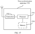
- a time synchronization apparatus exists in a product form of a chip.
- a structure of the apparatus includes a processor and a memory.
- the memory is configured to: be coupled to the processor, and store program instructions and data that are necessary for the apparatus.
- the processor is configured to execute the program instructions stored in the memory, so that the apparatus performs a function of the apparatus in the foregoing methods.
- Embodiments of this application provide a time synchronization method.
- the method is applicable to an architecture in which a centralized unit CU and a distributed unit DU are separated from each other.
- the CU-DU split architecture may be an architecture in a long term evolution (long term evolution, LTE) system, or may be an architecture in a 5G new radio (New Radio, NR) system. This is not limited in the embodiments of this application.
- the CU may be configured to: receive data, a request message, and the like that are reported by a terminal; generate a system information block (System information block, SIB), radio resource control (Radio Resource Control, RRC) dedicated signaling, and system broadcast signaling; and send the SIB, the RRC dedicated signaling, and the system broadcast signaling to the UE via the DU.
- the DU may be configured to: generate a MIB and a SIB, and send the MIB and the SIB to the terminal; receive service data, system broadcast, dedicated signaling, or the like from the CU, and send the service data, the system broadcast, the dedicated signaling, or the like to the terminal.
- the CU and the DU may be divided based on protocol layers of a wireless network.
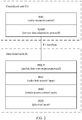
- a possible division manner is as follows:
- the CU is configured to perform functions of a radio resource control RRC protocol stack, a service data adaptation protocol (Service Data Adaptation Protocol, SDAP) protocol stack, and a packet data convergence protocol (Packet Data Convergence Protocol, PDCP) layer
- the DU is configured to perform functions of a radio link control (Radio Link Control, RLC) layer, a media access control (Media Access Control, MAC) layer, a physical (Physical) layer, and the like.
- RLC Radio Link Control
- MAC media access control
- Physical Physical
- the CU is configured to perform functions of an RRC protocol stack and an SDAP protocol stack
- the DU is configured to perform functions of a PDCP layer, an RLC layer, a MAC layer, a physical layer, and the like.
- FIG. 1 and FIG. 2 are merely descriptions of examples of division based on the protocol layers.
- a specific division manner of the CU-DU split architecture is not limited in the embodiments of this application.
- division of processing functions of the CU and the DU based on the protocol layers is merely an example, and the processing functions of the CU and the DU may alternatively be divided in another manner.
- the CU or the DU may be divided to have functions of more protocol layers.
- the CU or the DU may alternatively be divided to have some processing functions of protocol layers.
- some functions of the RLC layer and a function of a protocol layer above the RLC layer are distributed to the CU, and a remaining function of the RLC layer and a function of a protocol layer below the RLC layer are distributed to the DU.
- functions of the CU or the DU may alternatively be divided based on a service type or another system requirement.
- the CU may alternatively have one or more functions of a core network.
- One or more CUs may be disposed in a centralized manner or a separated manner.
- the CUs may be disposed on a network side for centralized management.
- the DU may have a plurality of radio frequency functions, and the radio frequency functions may be remotely set. This is not limited in the embodiments of this application.
- functions of the CU may be implemented by one entity, or may be implemented by different entities.
- the functions of the CU may be further divided.
- a control plane (control panel, CP) and a user plane (user panel, UP), namely, a control plane of the CU (CU-CP) and a user plane of the CU (CU-UP), are separated from each other.
- the CU-CP and the CU-UP may be implemented by different functional entities.
- the CU-CP and the CU-UP may be coupled to the DU to jointly implement functions of a base station.
- the CU and the DU may be connected through an interface, for example, an F1 interface.
- FIG. 1 and FIG. 3 are merely examples for description. Specific composition of the CU-DU split architecture is not limited in the embodiments of this application. Herein, only FIG. 1 to FIG. 3 are used as examples for description.
- an embodiment of this application provides a time synchronization method.
- a boundary of a system frame number in the following embodiments of this application may be a frame header boundary of the SFN, or may be a frame trailer boundary of the SFN. This is not limited in the embodiments of this application.
- an embodiment of this application provides a time synchronization method.
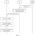
- the method includes steps S401 to S406.
- S401 A DU determines time information.
- a time unit of the time information meets preset precision.
- the time unit of the time information may be millisecond, microsecond, femtosecond, nanosecond, or another time unit of a smaller order of magnitude.
- the time unit of the time may be n microseconds, n nanoseconds, n femtoseconds, or n milliseconds, where n is greater than 0.
- a value of n is less than 10.
- a specific precision level of the time unit of the time information is not limited in this embodiment of this application, and descriptions herein are merely examples.
- the time information may be 11 o'clock, 10 minutes, 5 seconds, 10 milliseconds, 20 microseconds, and 15 nanoseconds on the eleventh day.
- the time information may be a first value relative to a reference time, where the first value may include values of a plurality of parameters, and the plurality of parameters may be corresponding to different time units.
- the time information may be a time relative to a preset time or reference time.
- the time information may be a global positioning system (Global Positioning System, GPS) time obtained by the DU from a clock source, and the GPS time is a time relative to a GPS start time (preset time).
- GPS Global Positioning System
- the GPS start time point may be 00:00:00 on Gregorian calendar date January 6, 1980.
- the time information may alternatively be a local time obtained by the DU from a clock source, and the local time is a time relative to a local start time (preset time).
- a value of the local start time point depends on implementation of an upper layer. For example, the value can be determined based on a local clock of a synchronization clock source.
- a DU determines time information may include: The DU obtains a GPS time from a clock source, and subtracts leap seconds (leap Seconds) from the GPS time to obtain a coordinated universal time (Coordinated Universal Time, UTC).
- the preset time may be a start time point of the UTC time, for example, 00:00:00 on Gregorian calendar date January 1, 1900 (at the midnight on Sunday, December 31, 1899, and Monday, January 1, 1900). It should be noted that a specific manner of determining the time information by the DU is not limited in this embodiment of this application, and descriptions herein are merely examples.
- the DU may obtain the GPS time from the clock source through the precision time protocol (Precision Time Protocol, PTP) of 1588 or 802.1as, and then determine the UTC time based on the GPS time.
- PTP Precision Time Protocol
- a clock synchronization functional entity in the DU may exchange a PTP message with a server of the clock source, to obtain the time information.
- the time information may further include one or more of time type information, compensation information, an offset between the UTC time and the local time, a leap second offset between the GPS time and the UTC time, other uncertain time information, or whether and how to apply a daylight saving time (daylight-saving time, daytime saving time).
- Specific content included in the time information is not limited in the embodiments of this application.
- the time information may include the GPS time and a leap second time, so that a terminal calculates the UTC time based on the GPS time and the leap second time.
- the time information may alternatively include the UTC time and a leap second time, so that the terminal calculates the GPS time based on the UTC time and the leap second time.
- the time information in step S401 may include a plurality of times, and each of the plurality of times may include identifier information of one clock domain.
- each of the plurality of times may be an offset relative to a reference time.
- a time may be an offset relative to the GPS time, the UTC time, or the local time.
- the DU may send a GPS time, a UTC time, or a local time to the terminal, and time information of another local time is a difference relative to the GPS time, the UTC time, or the local time.
- the time information may include a GPS time (11 o'clock, 10 minutes, 5 seconds, 10 milliseconds, 20 microseconds, and 15 nanoseconds on the eleventh day), and may further include 50 microseconds and 100 microseconds.
- the 50 microseconds are an offset relative to the GPS time (11 o'clock, 10 minutes, 5 seconds, 10 milliseconds, 20 microseconds, and 15 nanoseconds on the eleventh day).
- 11 o'clock, 10 minutes, 5 seconds, 10 milliseconds, 20 microseconds, and 15 nanoseconds on the eleventh day may be combined with the 50 microseconds to obtain a local time (11 o'clock, 10 minutes, 5 seconds, 10 milliseconds, 70 microseconds, and 15 nanoseconds on the eleventh day).
- the DU generates a system information block SIB.
- the SIB includes the time information but does not include a reference system frame number (System Frame Number, SFN), where the reference SFN is an SFN corresponding to the time information.
- SFN System Frame Number
- the time information in the SIB indicates a moment corresponding to a boundary of an SFN at which an end boundary of the system information SI window for sending the SIB is located. If the end boundary of the SI window is not aligned with the frame trailer of the SFN, the time information in the SIB indicates a moment corresponding to a boundary of an SFN immediately after an end boundary of the SI window for sending the SIB.
- the time information in the SIB indicates a moment corresponding to a boundary of an SFN at which a start boundary of the system information SI window for sending the SIB is located. If the start boundary of the SI window is not aligned with the frame header of the SFN, the time information in the SIB indicates a moment corresponding to a boundary of an SFN immediately after a start boundary of an SI window for sending the SIB.
- a specific moment that is corresponding to the boundary of the SFN and that is indicated by the time information is not limited, and the time information only needs to be corresponding to a moment corresponding to a boundary of an SFN.
- the SFN immediately after (immediately after) the end boundary of the SI window for sending the SIB may be a next SFN of the end boundary of the SI window for sending the SIB, or may be an N th SFN after the end boundary of the SI window for sending the SIB, where N is a natural number.
- N is a natural number.
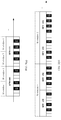
- the SFN immediately after the end boundary of the SI window for sending the SIB is a next SFN of the end boundary of the SI window for sending the SIB is used as an example for description below. For example, as shown in (a) in FIG. 5 , if the SI window for sending the SIB is an SI window 1, the SFN immediately after the end boundary of the SI window 1 may be an SFN 100.
- the SIB may include the time information and a reference SFN corresponding to the time information, where the time information indicates a moment corresponding to a boundary of the reference SFN.
- the time information in the SIB may be directly obtained from the clock source, or may be calculated based on a time obtained by the DU from the clock source.
- the time obtained by the DU from the clock source is a first time. If the first time is a moment corresponding to a boundary of the SFN 100, the DU may generate the SIB based on the first time and the SFN 100. If the first time is a time of an intermediate moment of the SFN 100, the DU may determine a second time based on the first time. The second time is obtained by adding 5 milliseconds to the first time. The second time is a moment corresponding to the boundary of the reference SFN (SFN 100). The DU then generates the SIB based on the second moment and the SFN 100. It may be understood that the second time may alternatively be another time obtained based on the first time, but the second time needs to indicate the moment corresponding to the boundary of the reference SFN.
- a type of the SIB may be a SIB16, a SIB9, or another newly added SIB, and the newly added SIB is a SIB other than a SIB specified in an existing protocol.
- the newly added SIB may be an SIB other than a SIB1 to a SIB9 that are specified in the TS38.331 protocol.
- the newly added SIB may be an SIB other than a SIB1 to a SIB26 that are specified in the TS36.331 protocol.
- a specific SIB generated by the DU is not limited, and descriptions herein are merely examples.
- the DU may generate a SIB16.
- the DU may generate a SIB9.
- the time information is added to the existing SIB9, or the time information and the reference SFN are added to the existing SIB9.
- the DU may alternatively generate the newly added SIB, which may be denoted as SIBX.
- the SIBX may include the time information but does not include the reference SFN, or may include the time information and the reference SFN. This is not limited in this embodiment of this application.
- the DU sends the SIB to a terminal UE.
- the DU may send the SIB including the time information to the UE by using a broadcast message.
- the UE may be all UEs in a cell.
- the DU may send the SIB to all the UEs in the cell in a broadcast manner.
- the DU may send information about the SIB after receiving a request message of the UE.
- the DU sends the SIB to the UE may include: The DU sends the SIB in a system information SI window. Specifically, the DU may send the SIB in the SI window of the reference SFN. It may be understood that, if the SIB includes the time information but does not include the reference SFN, the reference SFN is the SFN at which the end boundary of the system information SI window for sending the SIB is located, or the SFN immediately after the end boundary of the SI window for sending the SIB, and the time information in the SIB indicates the moment corresponding to the boundary of the reference SFN. If the SIB includes the time information and the reference SFN, the time information indicates the moment corresponding to the boundary of the reference SFN.
- the DU may determine, based on the time information, the moment corresponding to the boundary of the reference SFN. For example, if the reference SFN is the SFN 100, the moment corresponding to the boundary of the SFN 100 is the UTC time. If the reference SFN is an SFN 101, a moment corresponding to a boundary of the SFN 101 is a sum of the UTC time and a frame length of an SFN (10 ms).
- a frame length of the SFN is 10 ms.
- the DU may send the SIB in the SI window 1 of the SFN 100.
- a time in the SIB indicates a time at a boundary of the SFN (SFN 100) immediately after the end boundary of the SI window 1. That is, 11 o'clock, 10 minutes, 5 seconds, 10 milliseconds, 20 microseconds, and 15 nanoseconds on the eleventh day indicates the moment corresponding to the boundary of the SFN 100.
- the reference SFN is the SFN 100, and the time information in the SIB indicates the moment corresponding to the boundary of the SFN 100.
- the DU may send the SIB in the SI window 1 of the SFN 101, and a time (11 o'clock, 10 minutes, 5 seconds, 20 milliseconds, 20 microseconds, and 15 nanoseconds on the eleventh day) in the SIB indicates the time at the boundary of the SFN 101 at which the end boundary of the SI window 1 is located.
- a time 11 o'clock, 10 minutes, 5 seconds, 20 milliseconds, 20 microseconds, and 15 nanoseconds on the eleventh day
- the reference SFN is the SFN 101
- the time information in the SIB indicates the moment corresponding to the boundary of the SFN 101.
- the DU may send the SIB in the SI window of the SFN 100.
- a time (11 o'clock, 10 minutes, 5 seconds, 10 milliseconds, 20 microseconds, and 15 nanoseconds on the eleventh day) in the SIB indicates the moment corresponding to the boundary of the SFN 100.
- the DU may also send the SIB in any SFN after the reference SFN.
- the DU may send the SIB in an SI window of the SFN 101.
- An SFN in which the DU sends the SIB is not limited in this embodiment of this application, and descriptions herein are merely examples.
- the SFN corresponding to the time information may be any SFN in an SFN 0 to an SFN 1023.
- a frame number of a reference SFN corresponding to specific time information may be determined based on the time information.
- S404 The UE receives the SIB sent by the DU.
- an RRC layer of the UE receives the SIB sent by the DU.
- the UE may determine, based on the time information included in the SIB, the moment corresponding to the boundary of the reference SFN.
- the reference SFN is an SFN immediately after an end boundary of an SI window for sending the SIB. For example, as shown in (a) in FIG. 5 , if the UE receives the SIB in the SI window 1 of the SFN 100, the reference SFN is an SFN immediately after the end boundary of the SI window 1 in which the SIB is sent. That is, the reference SFN is the SFN 100. Therefore, the time information in the SIB indicates the moment corresponding to the boundary of the SFN 100.
- the reference SFN is an SFN at which an end boundary of an SI window for sending the SIB is located. For example, as shown in (b) in FIG. 5 , if the UE receives the SIB in the SI window 1, the reference SFN is an SFN at which the end boundary of the SI window 1 for sending the SIB is located. That is, the reference SFN is the SFN 101. Therefore, the time information in the SIB indicates the moment corresponding to the boundary of the SFN 101.
- the time information in the SIB indicates the moment corresponding to the boundary of the reference SFN.
- the UE may determine, based on the time information and the SFN 100 that are in the SIB, that the time information indicates a time at the boundary of the SFN 100.
- the UE may determine, based on the time information and the SFN 100 that are in the SIB, that the SFN 100 in the SIB is a system frame that is immediately after the SFN 101 in which the UE performs receiving and whose frame number is equal to the frame number of the reference SFN (SFN 100). That is, the time information in the SIB is corresponding to the time at the boundary of the SFN 100 immediately after the SFN 101 in which the UE performs receiving.
- step S404 may be that a plurality of UEs in a same cell receive the SIB broadcast by the DU.
- S405 The UE processes the time information to obtain a time reference.
- Step S405 may be understood as that the relative time is added to a time of the start time point to obtain the absolute time. It may be understood that, in a first case, the terminal receives GPS time information, and determines the time reference based on the received time information and a start time point (00:00:00 on Gregorian calendar date January 6, 1980).
- the terminal receives a local time, and determines the time reference based on the received time information and a start time specified by the upper layer.
- the terminal receives UTC time information, and calculates GPS time information based on the received time, a start time point (00:00:00 on Gregorian calendar date January 1, 1900), and leap second information.
- the UE may process the time information at the RRC layer to obtain the time reference.
- the start point of the time in the time information is 00:00:00 on Gregorian calendar date January 6, 1980 (starting from the GPS time), and the time should be added to the time in the time information when the time reference is determined.
- the time type information in the time information is set to a local clock, explanations of the start time point are not specified, and are made by the upper layer. That is, the upper layer (for example, an application layer) may specify the start time point.
- step S405 further includes: calculating uncertainty of the time reference based on the uncertainty and other uncertainty that is related to implementation.
- the SIB received by the UE may include a plurality of times, and each time may include identifier information of one clock domain.
- the SIB received by the UE may include a plurality of times, and each time may be an offset relative to a reference time.
- the time may be an offset relative to the GPS time, the UTC time, or a local time.
- the DU sends information about a GPS time, UTC time, or local time to the terminal, and time information of another local time is a difference relative to the GPS time, the UTC time, or the local time.
- the terminal may calculate a time reference of the clock domain based on the difference and the reference time.
- a clock domain based on which the UE determines the time reference may be specified in a protocol, or may be configured by a network.
- a plurality of terminals that are in a cell and that need to achieve high-precision time synchronization should use a time of a same clock domain.
- that the UE notifies the upper layer of the time reference may include: The UE notifies the upper layer of the time reference at the moment at the boundary of the reference SFN. It may be understood that the time in the time reference should be corresponding to the moment at the boundary of the reference SFN.
- the UE notifies the upper layer of the time reference may be that the UE notifies the time reference to a layer above the RRC, and the layer above the RRC may include a non-access stratum (Non-access stratum, NAS) layer, an application layer, or the like.
- NAS non-access stratum
- the reference SFN is an SFN immediately after the end boundary of the SI window 1 in which the SIB is sent. That is, the reference SFN is the SFN 100. It may be understood that, in this case, the UE may notify the time reference to the upper layer at the moment at the boundary of the SFN 100.
- the reference SFN is an SFN at which the end boundary of the SI window 1 for sending the SIB is located. That is, the reference SFN is the SFN 101. It may be understood that, in this case, the UE may notify the time reference to the upper layer at the moment at the boundary of the SFN 101.
- the UE may alternatively notify the upper layer of a first time reference at a first moment (an SFN other than the reference SFN) of a first SFN.
- a time in the first time reference indicates the first moment of the first SFN. For example, if the time reference is 11 o'clock, 10 minutes, 5 seconds, 10 milliseconds, 20 microseconds, and 15 nanoseconds on January 6, 1980, and the reference SFN is the SFN 100, the time reference indicates the moment corresponding to the boundary of the SFN 100.
- the UE may notify, at the boundary of the SFN 100, the upper layer of 11 o'clock, 10 minutes, 5 seconds, 10 milliseconds, 20 microseconds, and 15 nanoseconds on January 6, 1980; notify, at the boundary of the SFN 101, the upper layer of 11 o'clock, 10 minutes, 5 seconds, 20 milliseconds, 20 microseconds, and 15 nanoseconds on January 6, 1980; or notify, at an intermediate moment of the SFN 101, the upper layer of 11 o'clock, 10 minutes, 5 seconds, 15 milliseconds, 20 microseconds, and 15 nanoseconds on January 6, 1980.
- a specific moment at which the UE notifies the upper layer of the time reference is not limited in this embodiment of this application. However, the moment at which the UE notifies the upper layer of the time reference should be corresponding to the time in the time reference.
- the application layer of the UE may implement time synchronization between the UE and a network side based on the time reference, thereby indirectly achieving time synchronization between UEs. It may be understood that the UE may send the determined time reference to another device by using time synchronization signaling.
- the DU obtains the time information.
- the DU generates the system information block SIB.
- the DU sends the SIB to the terminal UE.
- the UE receives the SIB sent by the DU.
- the UE processes the time information to obtain the time reference.
- the UE notifies the upper layer of the time reference.
- the DU generates the SIB including the time information, and sends the SIB to all the UEs in the cell, so that the UEs can determine, based on the time information in the SIB, the moment at the boundary of the reference SFN corresponding to the time information. Therefore, in a CU-DU split architecture, time synchronization between the terminals in the cell is implemented.
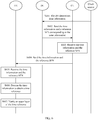
- An embodiment of this application further provides a time synchronization method. As shown in FIG. 6 , the method includes steps S601 to S605.
- a DU determines time information.
- step S601 an implementation of obtaining the time information by the DU in step S601 is the same as the implementation in step S401.
- step S401 For details, refer to descriptions in step S401. Details are not described herein again.
- the DU sends the time information and a reference SFN corresponding to the time information to a CU.
- the time information indicates a moment corresponding to a boundary of the reference SFN.
- that the DU sends the time information and the reference SFN to the CU may include: The DU generates a system information block SIB, where the SIB includes the time information and the reference SFN.
- the DU sends the SIB to the CU.
- the DU may add the time information and the reference SFN corresponding to the time information to the SIB, and then send the SIB to the CU.
- that the DU sends the time information and the reference SFN to the CU may include: The DU adds only the time information to the SIB, and sends the time information in the SIB and the reference SFN to the CU.
- the time information and the reference SFN may be placed in one information element (information element) and sent to the CU as a character string, or the time information and the reference SFN may be separately placed in two information elements and sent to the CU.
- the time information and the reference SFN may alternatively be sent in one message, or may be separately sent in two messages. It should be noted that a specific manner of sending the time information and the reference SFN is not limited in this embodiment of this application, and descriptions herein are merely examples.
- the SIB may be a SIB9, a SIB16, or another newly added SIB.
- the newly added SIB has been described in the foregoing embodiment, and details are not described herein again.
- the method may further include: The CU sends a request message to the DU, where the request message is used to request the time information and the reference SFN corresponding to the time information. After receiving the request message from the CU, the DU sends the time information and the reference SFN to the CU.
- the CU may configure the DU to report time information corresponding to a frame header boundary or frame trailer boundary of the SFN.
- the CU includes an SFN number in the request message.
- the DU After receiving the request message, the DU sends time information corresponding to a boundary of the SFN number to the CU.
- the CU may configure clock domains, where time information of the clock domains is reported by the DU.
- the CU includes identifier information of a clock domain in the request message.
- the DU After receiving the request message, the DU sends time information corresponding to an identifier of the clock domain to the CU.
- the DU may notify the CU of time information of a clock domain required by the terminal.
- the CU may alternatively configure or request the DU to report time information required by a terminal.
- the CU may configure the DU to report the time information of the clock domain required by the terminal. That is, the foregoing methods may be used in combination.
- the DU may further periodically report the time information and the SFN corresponding to the time information to the CU.
- the reporting periodicity may be indicated by the CU, or may be locally configured. This is not limited in this embodiment of this application.
- the DU may send the time information and the SFN corresponding to the time information to the CU through an F1 interface between the DU and the CU.
- the CU receives the time information and the reference SFN.
- the CU may determine the moment corresponding to the boundary of the reference SFN by receiving the time information and the reference SFN that are sent by the DU. Therefore, in this embodiment, the CU does not need to maintain the SFN number like the DU.
- the CU sends the time information and the reference SFN to UE.
- that the CU sends the time information and the SFN corresponding to the time information to the UE includes: The CU sends the time information and the SFN corresponding to the time information to the UE by using dedicated signaling.
- the CU may encapsulate the time information and the reference SFN corresponding to the time information that are sent by the DU, and send the time information and the reference SFN to the UE by using RRC signaling.
- the dedicated signaling may indicate the identifier information of the clock domain corresponding to the time information.
- the CU may send dedicated signaling that includes the time information and the reference SFN to the DU, and then the DU forwards the dedicated signaling to the UE.
- the UE when the CU sends the RRC signaling to the UE in a unicast manner in step S604, the UE is UE in a cell.
- the UE receives the time information and the reference SFN.
- the UE receives the time information and the reference SFN corresponding to the time information, and may determine, based on the time information, the moment corresponding to the boundary of the SFN.
- the time information received by the UE is 11 o'clock, 10 minutes, 5 seconds, 10 milliseconds, 20 microseconds, and 15 nanoseconds
- the reference SFN is an SFN 100
- the time information indicates the moment corresponding to the boundary of the SFN 100.
- the UE may determine, based on the time information and the SFN 100, that the SFN 100 is a system frame that is immediately after the SFN 101 in which the UE performs receiving and whose frame number is equal to a frame number (SFN 100) of the reference SFN. That is, the time information is corresponding to the time at the boundary of the SFN 100 immediately after the SFN 101 in which the UE performs receiving.
- steps S606 and S607 are the same as those of steps S405 and S406. For details, refer to descriptions of steps S405 and S406. Details are not described herein again.
- the UE may determine, based on the time information, the moment corresponding to the boundary of the reference SFN, convert the time information into an absolute time, and notify the upper layer of the time reference, to implement time synchronization between the terminal and a network device. In this way, time synchronization between UEs is indirectly achieved.
- the DU obtains the time information.
- the DU sends the time information and the reference SFN corresponding to the time information to the CU.
- the CU receives the time information and the reference SFN.
- the CU sends the time information and reference SFN to the UE.
- the UE receives the time information and the reference SFN.
- the UE processes the time information to obtain the time reference.
- the UE notifies the upper layer of the time reference.
- the DU sends the time information and the reference SFN corresponding to the time information to the CU.
- the CU may send the correspondence between the time information and the SFN to the UE by using the dedicated signaling, so that time synchronization between terminals in a cell is implemented in a CU-DU split architecture.
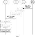
- An embodiment of this application provides still another time synchronization method. As shown in FIG. 7 , the method includes steps S701 to S707.
- S701 A CU determines time information.
- step S701 an implementation of obtaining the time information by the CU in step S701 is the same as the implementation of obtaining the time information by the DU in step S401.
- step S401 For details, refer to descriptions in step S401. Details are not described herein again.
- This step is optional.
- S702 The CU performs time synchronization with a DU based on the time information.
- the CU may perform time synchronization with the DU based on the time information obtained from a clock source, to implement time synchronization between the CU and the DU.
- a specific method for performing time synchronization between the CU and the DU is not limited in this embodiment of this application, and time synchronization between the CU and the DU may be implemented according to a method for synchronizing two nodes in TS38.331.
- steps S703 to S707 are the same as those of steps S402 to S406. For details, refer to descriptions of steps S402 to S406. Details are not described herein again.
- the CU obtains the time information, and performs time synchronization with the DU, so that the SFN maintained by the DU may be corresponding to the time information.
- the DU sends the time information and the reference SFN corresponding to the time information to the UE, so that the UE determines, based on the time information, the moment corresponding to the boundary of the reference SFN corresponding to the time information, thereby implementing time synchronization.
- This embodiment of this application provides the time synchronization method.
- the CU obtains the time information.
- the CU performs time synchronization with the DU based on the time information.
- the DU generates the system information block SIB.
- the DU sends the SIB to the terminal UE.
- the UE receives the SIB sent by the DU.
- the UE processes the time information to obtain the time reference.
- the UE notifies the upper layer of the time reference.
- the DU obtains the time information, and performs time synchronization with the DU, so that the SFN maintained by the DU is synchronized with the time information.
- the DU generates the SIB including the time information, and sends the SIB to all UEs in a cell, so that the UEs can determine, based on the time information in the SIB, the moment at the boundary of the reference SFN corresponding to the time information. Therefore, in a CU-DU split architecture, time synchronization between the terminals in the cell is implemented.
- An embodiment of this application provides still another time synchronization method. As shown in FIG. 8 , the method includes steps S801 to S808.
- S801 A CU determines time information.
- step S801 an implementation of obtaining the time information by the CU in step S801 is the same as the implementation of obtaining the time information by the DU in step S401.
- step S401 For details, refer to descriptions in step S401. Details are not described herein again.
- S802 The CU performs time synchronization with a DU based on the time information.
- step S802 an implementation of performing time synchronization with the DU by the CU based on the time information in step S802 is the same as the implementation of step S702. For details, refer to descriptions in step S702. Details are not described herein again.
- the DU sends the time information and a reference SFN corresponding to the time information to a CU.
- the DU may perform step S803 after receiving a request from the CU or reporting a configuration.
- the CU receives the time information and the reference SFN.
- S805 The CU sends time information and a reference SFN to UE.
- the CU performs time synchronization with the DU, and receives the time information and the reference SFN that are sent by the DU, so that the CU and the DU can maintain SFNs synchronously. Therefore, the time information and the reference SFN that are sent by the CU to the UE in step S805 may be different from the time information and the reference SFN in steps S801 to S804. That is, the time information and the reference SFN that are sent to the UE in step S805 may be: After obtaining new time information from a clock source, the CU sends a new reference SFN corresponding to the new time information to the UE based on the SFN number autonomously maintained by the CU.
- the CU obtains the time information. Because the CU does not maintain an SFN, the CU may maintain the SFN numbers synchronously with the DU based on the time information and the reference SFN that are sent by the DU, and autonomously sends dedicated signaling to the UE, to notify the UE of a moment corresponding to a boundary of the reference SFN. That is, in this embodiment, after time synchronization is performed between the DU and the CU, the DU sends the time information and the reference SFN to the CU, so that the CU and the DU maintain the SFN synchronously.
- This embodiment of this application provides the time synchronization method.
- the CU obtains the time information.
- the CU performs time synchronization with the DU based on the time information.
- the DU sends the time information and the reference SFN corresponding to the time information to the CU.
- the CU receives the time information and the reference SFN.
- the CU sends the time information and reference SFN to the UE.
- the UE receives the time information and the reference SFN.
- the UE processes the time information to obtain the time reference.
- the UE notifies the upper layer of the time reference.
- time synchronization is performed between the CU and the DU, and the CU receives the time information and the reference SFN that are sent by the DU, so that the CU and the DU can maintain SFNs synchronously, and send the time information and the reference SFN to the UE by using dedicated signaling based on the autonomously maintained SFN.
- the CU and the DU can maintain the SFN synchronously, to implement time synchronization between terminals in a cell.
- An embodiment of this application provides yet another time synchronization method. As shown in FIG. 9 , the method is performed when a time of a CU is synchronized with a time of a DU and an SFN maintained by the CU is synchronized with an SFN maintained by the DU.
- the method includes steps S901 to S908.
- S901 A CU determines time information.
- step S901 an implementation of obtaining the time information by the CU in step S901 is the same as the implementation of obtaining the time information by the DU in step S401.
- steps S401 Details are not described herein again.
- S902 The CU generates a SIB.
- the SIB includes time information and a reference SFN corresponding to the time information, where the time information is a moment corresponding to a boundary of the reference SFN.
- a type of the SIB may be a SIB16, a SIB9, or a SIBX.
- the SIBX is a newly added SIB.
- the newly added SIB has been described in the foregoing embodiment, and details are not described herein again.
- a specific SIB generated by the CU is not limited, and descriptions herein are merely examples. It may be understood that, compared with an existing SIB, in the SIB, the time information and the reference SFN are added to the existing SIB.
- S903 The CU sends the SIB to a DU.
- the CU may send the generated SIB to the DU through an F1 interface between the CU and the DU.
- the CU autonomously maintains an SFN, and sends the time information and the reference SFN to the DU, to assist the DU in obtaining a correspondence between the time information and the reference SFN.
- the CU may perform step S903 after receiving a request from the DU or reporting a configuration.
- steps S905 to S907 are the same as those of steps S403 to S406. For details, refer to descriptions of steps S403 to S406. Details are not described herein again.
- time and SFN synchronization between the CU and the DU may be implemented by performing steps S801 to S804.
- This embodiment of this application provides the time synchronization method.
- the CU obtains the time information.
- the CU generates the SIB.
- the CU sends the SIB to the DU.
- the DU receives the SIB.
- the DU sends the SIB to the UE.
- the UE receives the SIB sent by the DU.
- the UE processes the time information to obtain the time reference.
- the UE notifies the upper layer of the time reference.
- the CU autonomously maintains the SFN, and assists the DU in obtaining the correspondence between the time information and the reference SFN.
- the DU sends the correspondence to the UE by using a broadcast message, so that time synchronization between terminals in the cell can be implemented in a CU-DU split architecture.
- An embodiment of this application provides yet another time synchronization method. As shown in FIG. 10 , the method is performed when a time of a CU is synchronized with a time of a DU and an SFN maintained by the CU is synchronized with an SFN maintained by the DU. The method includes steps S1001 to S1008.
- S1001 A CU determines time information.
- step S1001 an implementation of obtaining the time information by the CU in step S1001 is the same as the implementation of obtaining the time information by the DU in step S401.
- step S401 For details, refer to descriptions in step S401. Details are not described herein again.
- the CU sends the time information and a reference SFN corresponding to the time information to a DU.
- the CU autonomously maintains the SFN number. Therefore, the CU sends the time information and the reference SFN to the DU, to assist the DU in obtaining the time reference.
- the CU may perform step S1002 after receiving a request from the DU or reporting a configuration.
- time and SFN synchronization between the CU and the DU may be implemented by performing steps S801 to S804.
- the CU may place the time information and the reference SFN in one information element (information element), and send the information element to the CU as a character string.
- the CU may separately place the time information and the reference SFN in two information elements, and send the information elements to the DU.
- a specific manner of sending the time information and the reference SFN is not limited in this embodiment of this application, and descriptions herein are merely examples.
- steps S1004 to S1008 are the same as those of steps S402 to S406. For details, refer to descriptions of steps S402 to S406. Details are not described herein again.
- This embodiment of this application provides the time synchronization method.
- the CU obtains the time information.
- the CU sends the time information and the reference SFN corresponding to the time information to the DU.
- the DU receives the time information and the reference SFN.
- the DU sends the time information and reference SFN to the UE by using the SIB.
- the UE processes the time information to obtain the time reference.
- the UE notifies the upper layer of the time reference.
- the CU when the time and the SFN of the CU are synchronized with the time and the SFN of the DU, the CU sends the time information and the SFN corresponding to the time information to the DU, to assist the DU in obtaining the time information and the reference SFN, thereby implementing time synchronization between terminals.
- An embodiment of this application provides yet another time synchronization method. As shown in FIG. 11 , the method is performed when a time of a CU is synchronized with a time of a DU and an SFN maintained by the CU is synchronized with an SFN maintained by the DU.
- the method includes steps S1101 to S1105.
- the CU autonomously maintains an SFN, and after obtaining the time information from a clock source, the CU sends, based on the autonomously maintained SFN number, the reference SFN corresponding to the time information to the UE.
- steps S1103 to S1105 are the same as those of steps S605 to S607. For details, refer to descriptions of steps S605 to S607. Details are not described herein again.
- This embodiment of this application provides the time synchronization method.
- the CU obtains the time information.
- the CU sends the time information and the reference SFN corresponding to the time information to the UE.
- the UE receives the time information and the reference SFN.
- the UE processes the time information to obtain the time reference.
- the UE notifies the upper layer of the time reference.
- the CU sends the time information and the reference SFN corresponding to the time information to the UE by using the SFN autonomously maintained by the CU, to implement time synchronization between terminals in a cell in a CU-DU split architecture.
- An embodiment of this application further provides yet another time synchronization method. As shown in FIG. 12 , the method includes steps S1201 to S1206.
- a first base station determines first time information of a first cell.
- the first cell is any cell served by the first base station.
- a time unit of the first time information may be millisecond, microsecond, femtosecond, nanosecond, or another time unit of a smaller order of magnitude.
- a specific precision level of the time unit of the time information is not limited in this embodiment of this application, and descriptions herein are merely examples. For the time unit, refer to descriptions in the foregoing embodiments, and details are not described herein again.
- a first base station determines first time information of a first cell may be: A DU or a CU of the first base station determines the first time information.
- the first base station sends the first time information and a first reference SFN corresponding to the first time information to a second base station.
- the first time information is a moment corresponding to a boundary of the first reference SFN
- the first base station sends the first time information of the first cell and the first reference SFN to the second base station.
- the second time information is a moment corresponding to a boundary of the second reference SFN.
- the second cell is any cell served by the second base station.
- step S1204 may include: The second base station determines an SFN deviation and an intra-frame deviation between the first cell and the second cell.
- the second base station determines the second time information and second SFN based on the SFN deviation, the intra-frame deviation, the first time information, and the first reference SFN.
- the SFN deviation and the intra-frame deviation may be reported to the second base station via a terminal.
- the SFN deviation and the intra-frame deviation may be reported to the first base station via a terminal, and then sent to the second base station by the first base station.
- the second base station automatically detects downlink information of the first base station, to determine the SFN deviation and the intra-frame deviation.
- a specific manner of determining the SFN deviation and the intra-frame deviation by the second base station is not limited in this embodiment of this application.
- time information of the first cell is 10 o'clock
- 10 o'clock is a moment corresponding to a frame trailer boundary of an SFN 100
- an SFN of the first cell is an SFN 100
- an SFN of the second cell is an SFN 103
- the intra-frame deviation of the two cells is 5 milliseconds.
- the time information (10 o'clock and 5 milliseconds) of the second cell is a moment corresponding to a frame trailer boundary of the SFN 103. Therefore, the second time information may be 10 o'clock and 5 milliseconds, and the second reference SFN may be the SFN 103.
- the second time information may alternatively be 10 o'clock and 15 milliseconds.
- the second reference SFN is an SFN 104, and 10 o'clock and 15 milliseconds is a moment corresponding to a frame trailer boundary of the SFN 104.
- the first time information may be 9 o'clock, 59 seconds, and 55 milliseconds.
- the second reference SFN is an SFN 102, and 9 o'clock, 59 seconds, and 55 milliseconds is a moment corresponding to a frame trailer boundary of the SFN 102. This is not limited in this embodiment of this application.
- the second time information should be the moment corresponding to the boundary of the second reference SFN.
- only an example in which the boundary of the SFN is a frame trailer boundary of the SFN is used for description.
- the second base station sends the second time information and the second reference SFN to a terminal UE.
- the second base station may send the second time information and the second reference SFN to the UE in a broadcast or unicast manner.
- the second base station may send the second time information and the second reference SFN to the UE in a broadcast or unicast manner.
- the UE receives the second time information and the second reference SFN.
- the UE may implement time synchronization between the UE and a network side based on a correspondence between the second time and the second reference SFN, thereby implementing time synchronization between terminals in the second cell.
- a correspondence between time information of a cell of a base station and a reference SFN can be determined by using a correspondence between a reference SFN and time information obtained by another base station from the clock source, to implement time synchronization between terminals in the cell of the base station.
- the first base station obtains the first time information of the first cell.
- the second base station receives the first time information and the first reference SFN.
- the second base station determines the second time information and the second reference SFN that are of the second cell based on the first time information and the first reference SFN.
- the second base station sends the second time information and the second reference SFN to the terminal UE.
- the UE receives the second time information and the second reference SFN, thereby implementing time synchronization between UEs.
- the another base station assists the base station in determining a correspondence between time information and a reference SFN, so that costs of obtaining the time information from the clock source by the base station can be reduced while time synchronization is implemented.
- the CU and the DU may be divided into functional modules based on the foregoing method examples.
- each functional module may be obtained through division based on each corresponding function, or two or more functions may be integrated into one processing module.
- the integrated module may be implemented in a form of hardware, or may be implemented in a form of a software functional module. It should be noted that module division in the embodiments of this application is an example, and is merely a logical function division. During actual implementation, another division manner may be used.
- FIG. 14 is a possible schematic structural diagram of a time synchronization apparatus in the foregoing embodiments.
- the time synchronization apparatus 1400 includes a processor 1401, a transmitter 1402, and a receiver 1403.
- the processor 1401 may be configured to support the time synchronization apparatus 1400 in performing S401 and S402 in FIG. 4 , S601 in FIG. 6 , S703 in FIG. 7 , or S1004 in FIG. 10 .
- the transmitter 1402 may be configured to support the time synchronization apparatus 1400 in performing S403 in FIG. 4 , S602 in FIG. 6 , S704 in FIG. 7 , S803 in FIG. 8 , S905 in FIG.
- the receiver 1403 is configured to support the time synchronization apparatus 1400 in performing S904 in FIG. 9 or S1003 in FIG. 10 . All related content of the steps in the foregoing method embodiments may be cited in function descriptions of a corresponding functional module, and details are not described herein again. It may be understood that the time synchronization apparatus 1400 may be the DU device in the foregoing embodiments.
- FIG. 15 is a possible schematic structural diagram of a time synchronization apparatus in the foregoing embodiments.
- the time synchronization apparatus 1500 includes a receiver 1501, a transmitter 1502, and a processor 1503.
- the receiver 1501 may be configured to support the time synchronization apparatus 1500 in performing S603 in FIG. 6 or S804 in FIG. 8 .
- the transmitter 1502 may be configured to support the time synchronization apparatus 1500 in performing S604 in FIG. 6 , S805 in FIG. 8 , S903 in FIG. 9 , S1102 in FIG. 10 , or S1102 in FIG. 11 .
- the processor 1503 maybe configured to support the time synchronization apparatus 1500 in performing S701 and S702 in FIG.
- time synchronization apparatus 1500 may be the CU device in the foregoing embodiments.
- FIG. 16 is a possible schematic structural diagram of a terminal UE in the foregoing embodiments.
- the UE 1600 includes a receiver 1601, a processor 1602, and a transmitter 1603.
- the receiver 1601 may be configured to support the UE 1600 in performing S404 in FIG. 4 , S605 in FIG. 6 , S705 in FIG. 7 , S806 in FIG. 8 , S906 in FIG. 9 , S1006 in FIG. 10 , or S1103 in FIG. 11 .
- the processor 1602 may be configured to support the UE 1600 in performing S405 in FIG. 4 , S606 in FIG. 6 , S706 in FIG. 7 , S807 in FIG.
- the transmitter 1603 may be configured to support the UE 1600 in performing S406 in FIG. 4 , S607 in FIG. 6 , S707 in FIG. 7 , S808 in FIG. 8 , S908 in FIG. 9 , S1008 in FIG. 10 , or S1105 in FIG. 11 . All related content of the steps in the foregoing method embodiments may be cited in function descriptions of a corresponding functional module, and details are not described herein again.
- FIG. 17 is a schematic diagram of a possible schematic structural diagram of a time synchronization apparatus 1700 in the foregoing embodiments.
- the time synchronization apparatus 1700 includes a processor 1701 and a transceiver 1702.
- the processor 1701 is configured to control and manage an action of the time synchronization apparatus 1700.
- the processor 1701 is configured to support the time synchronization apparatus 1700 in performing S401 and S402 in FIG. 4 , S601 in FIG. 6 , S701 to S703 in FIG. 7 , S801 and S802 in FIG. 8 , S901 and S902 in FIG. 9 , S1001 and S1004 in FIG. 10 , S1101 in FIG.
- the transceiver 1702 is configured to perform S403 in FIG. 4 , S602 to S604 in FIG. 6 , S704 in FIG. 7 , S803 to S805 in FIG. 8 , S903 to S905 in FIG. 9 , S1002, S1003, and S1005 in FIG. 10 , S1102 in FIG. 11 , or S1202 and S1203 in FIG. 12 .
- the time synchronization apparatus 1700 may further include a memory 1703.
- the memory 1703 is configured to store program code and data that are corresponding to any foregoing time synchronization method performed by the time synchronization apparatus 1700.
- the memory 1703 may be a read-only memory (read-only memory, ROM), another type of static storage device capable of storing static information and instructions, a random access memory (random access memory, RAM), or the like.
- the method or algorithm steps described with reference to the content disclosed in this application may be implemented by hardware, or may be implemented by a processor by executing software instructions.
- the software instructions may include a corresponding software module.
- the software module may be stored in a random access memory (Random Access Memory, RAM), a flash memory, an erasable programmable read-only memory (Erasable Programmable ROM, EPROM), an electrically erasable programmable read-only memory (Electrically EPROM, EEPROM), a register, a hard disk, a removable hard disk, a compact disc read-only memory (CD-ROM), or any other form of storage medium well-known in the art.
- RAM Random Access Memory
- EPROM erasable programmable read-only memory
- EPROM electrically erasable programmable read-only memory
- CD-ROM compact disc read-only memory
- a storage medium is coupled to a processor, so that the processor can read information from the storage medium and write information into the storage medium.
- the storage medium may alternatively be a component of the processor.
- the processor and the storage medium may be located in an ASIC.
- the ASIC may be located in a core network interface device.
- the processor and the storage medium may alternatively exist as discrete components in a core network interface device.
- the computer-readable medium includes a computer storage medium and a communications medium, where the communications medium includes any medium that facilitates transmission of a computer program from one place to another.
- the storage medium may be any available medium accessible to a general-purpose computer or a dedicated computer.
Landscapes
- Engineering & Computer Science (AREA)
- Computer Networks & Wireless Communication (AREA)
- Signal Processing (AREA)
- Radar, Positioning & Navigation (AREA)
- Remote Sensing (AREA)
- Physics & Mathematics (AREA)
- General Physics & Mathematics (AREA)
- Mobile Radio Communication Systems (AREA)
- Electrophonic Musical Instruments (AREA)
- Communication Control (AREA)
- Synchronisation In Digital Transmission Systems (AREA)
Applications Claiming Priority (2)
| Application Number | Priority Date | Filing Date | Title |
|---|---|---|---|
| CN201910013535.5A CN111417186B (zh) | 2019-01-07 | 2019-01-07 | 一种时间同步方法和装置 |
| PCT/CN2019/126790 WO2020143426A1 (fr) | 2019-01-07 | 2019-12-19 | Procédé et appareil de synchronisation temporelle |
Publications (2)
| Publication Number | Publication Date |
|---|---|
| EP3890411A1 true EP3890411A1 (fr) | 2021-10-06 |
| EP3890411A4 EP3890411A4 (fr) | 2022-01-19 |
Family
ID=71493948
Family Applications (1)
| Application Number | Title | Priority Date | Filing Date |
|---|---|---|---|
| EP19909240.4A Pending EP3890411A4 (fr) | 2019-01-07 | 2019-12-19 | Procédé et appareil de synchronisation temporelle |
Country Status (7)
| Country | Link |
|---|---|
| US (1) | US12082131B2 (fr) |
| EP (1) | EP3890411A4 (fr) |
| JP (1) | JP7359342B2 (fr) |
| CN (1) | CN111417186B (fr) |
| AU (1) | AU2019420455B9 (fr) |
| BR (1) | BR112021013285A2 (fr) |
| WO (1) | WO2020143426A1 (fr) |
Cited By (1)
| Publication number | Priority date | Publication date | Assignee | Title |
|---|---|---|---|---|
| WO2023073246A3 (fr) * | 2021-11-01 | 2023-06-08 | Telefonaktiebolaget Lm Ericsson (Publ) | Appareil et procédés de pré-compensation de réseau d'informations de temps de référence dans une architecture divisée |
Families Citing this family (18)
| Publication number | Priority date | Publication date | Assignee | Title |
|---|---|---|---|---|
| US20220124654A1 (en) * | 2019-01-09 | 2022-04-21 | Ntt Docomo, Inc. | Terminal and communication method |
| US20220200733A1 (en) * | 2019-04-26 | 2022-06-23 | Ntt Docomo, Inc. | Radio base station |
| CN117768994A (zh) * | 2019-08-02 | 2024-03-26 | 中兴通讯股份有限公司 | 信息配置方法、用户设备、基站及存储介质 |
| EP3815428B1 (fr) * | 2019-08-14 | 2025-05-07 | Nokia Solutions and Networks Oy | Améliorations de distribution d'informations de système |
| US20230171717A1 (en) * | 2020-04-28 | 2023-06-01 | Mediatek Singapore Pte. Ltd. | System Information Design For Synchronization In Non-Terrestrial Network Communications |
| CN113810987B (zh) * | 2020-06-12 | 2025-09-02 | 中兴通讯股份有限公司 | 时间同步方法、电子设备、服务器及存储介质 |
| US12323931B2 (en) * | 2020-08-19 | 2025-06-03 | Qualcomm Incorporated | Reporting a synchronization signal block configuration to a control unit |
| EP4199568B1 (fr) * | 2020-08-28 | 2024-11-27 | Guangdong Oppo Mobile Telecommunications Corp., Ltd. | Compensation de délai de transmission |
| EP4221374A4 (fr) | 2020-10-21 | 2023-11-22 | Huawei Technologies Co., Ltd. | Procédé et appareil de communication |
| CN112566232B (zh) * | 2020-11-08 | 2022-05-17 | 临沂中科睿鹤智慧科技有限公司 | 一种无线物联网多终端间数据同步方法及系统 |
| CN114666889B (zh) * | 2020-12-23 | 2025-08-29 | 大唐移动通信设备有限公司 | 一种定位方法、装置、设备和可读存储介质 |
| CN115002891A (zh) * | 2021-03-02 | 2022-09-02 | 北京佰才邦技术股份有限公司 | 一种无线时间同步方法、装置及设备 |
| WO2022213278A1 (fr) * | 2021-04-06 | 2022-10-13 | Nokia Shanghai Bell Co., Ltd. | Correction d'erreurs systématiques d'horloge de référence d'un équipement utilisateur |
| CN115514441A (zh) * | 2021-06-22 | 2022-12-23 | 上海朗帛通信技术有限公司 | 一种被用于无线通信的方法和设备 |
| CN115767705A (zh) * | 2021-09-03 | 2023-03-07 | 中兴通讯股份有限公司 | 一种本地时钟校准方法、用户终端及计算机可读存储介质 |
| WO2023102729A1 (fr) * | 2021-12-07 | 2023-06-15 | 北京小米移动软件有限公司 | Procédé et appareil de détermination de temps système, procédé et appareil d'indication de position temporelle, et procédé et appareil d'envoi de requête |
| US20230217391A1 (en) * | 2021-12-30 | 2023-07-06 | Qualcomm Incorporated | System information block delivery in sidelink |
| CN117223304A (zh) * | 2022-04-12 | 2023-12-12 | 北京小米移动软件有限公司 | 传输同步方法及装置、存储介质 |
Family Cites Families (25)
| Publication number | Priority date | Publication date | Assignee | Title |
|---|---|---|---|---|
| CN102056283B (zh) * | 2009-10-27 | 2013-10-16 | 电信科学技术研究院 | 移动通信系统中时间同步的方法、系统及装置 |
| CN102083194B (zh) * | 2009-11-30 | 2014-12-03 | 电信科学技术研究院 | 时间信息发送与时间同步方法、系统和设备 |
| CN103796296B (zh) * | 2012-11-02 | 2018-05-08 | 中国移动通信集团公司 | 长期演进系统中的时间同步方法、用户设备及基站 |
| WO2014168537A1 (fr) * | 2013-04-12 | 2014-10-16 | Telefonaktiebolaget L M Ericsson (Publ) | Synchronisation de numéros de trame système |
| CN105228240B (zh) * | 2015-10-15 | 2018-10-16 | 北京北方烽火科技有限公司 | 一种定时同步方法、设备及基站 |
| US10292093B2 (en) * | 2015-11-10 | 2019-05-14 | Qualcomm Incorporated | Communicating subframe timing of an access point on a shared communication medium |
| EP4429296A3 (fr) | 2016-08-09 | 2024-12-11 | Samsung Electronics Co., Ltd | Procédé et appareil de gestion de fonctionnement de plan utilisateur dans un système de communication sans fil |
| CN113163442A (zh) | 2017-03-16 | 2021-07-23 | 北京小米移动软件有限公司 | 截断缓冲区状态报告 |
| US10582560B2 (en) | 2017-03-17 | 2020-03-03 | Ofinno, Llc | Radio access network notification area update failure |
| US10568007B2 (en) * | 2017-03-22 | 2020-02-18 | Comcast Cable Communications, Llc | Handover random access |
| US11122470B2 (en) * | 2017-05-04 | 2021-09-14 | Ofinno, Llc | Network slice information for handover procedure |
| FI4013122T3 (fi) * | 2017-05-04 | 2025-09-16 | Beijing Xiaomi Mobile Software Co Ltd | Säteilykeiloihin perustuva mittauskonfiguraatio |
| CN109151997B (zh) * | 2017-06-15 | 2023-03-10 | 中兴通讯股份有限公司 | 寻呼消息的发送方法、装置及存储介质 |
| CN109150562B (zh) * | 2017-06-16 | 2022-10-28 | 中兴通讯股份有限公司 | 管理小区的方法及装置、存储介质 |
| US10499376B2 (en) * | 2017-06-16 | 2019-12-03 | Kt Corporation | Methods for managing resource based on open interface and apparatuses thereof |
| US20180376380A1 (en) * | 2017-06-23 | 2018-12-27 | Huawei Technologies Co., Ltd. | Exposure of capabilities of central units and distributed units in base station entities for admission control |
| US10690778B2 (en) * | 2017-09-15 | 2020-06-23 | Qualcomm Incorporated | Validation of time assistance data to reduce satellite positioning degradation |
| US11233594B2 (en) * | 2017-12-19 | 2022-01-25 | Qualcomm Incorporated | Time synchronization for wireless communications |
| US10939400B2 (en) * | 2017-12-19 | 2021-03-02 | Qualcomm Incorporated | Time synchronization techniques for wireless communications |
| US11115942B2 (en) * | 2018-01-31 | 2021-09-07 | Qualcomm Incorporated | Scheduling for a time-synchronized wireless network |
| US11297541B2 (en) * | 2018-08-17 | 2022-04-05 | Qualcomm Incorporated | Signaling timing information for a time sensitive network in a wireless communications system |
| US11172397B2 (en) * | 2018-10-15 | 2021-11-09 | Qualcomm Incorporated | Timing information for multiple periodic traffic streams sharing a same quality of service |
| US20210392601A1 (en) * | 2018-10-16 | 2021-12-16 | Ntt Docomo, Inc. | Terminal and communication method |
| TWI735052B (zh) * | 2018-11-27 | 2021-08-01 | 瑞典商Lm艾瑞克生(Publ)電話公司 | 處理精確時序協定框之裝置及方法 |
| US20220200733A1 (en) * | 2019-04-26 | 2022-06-23 | Ntt Docomo, Inc. | Radio base station |
-
2019
- 2019-01-07 CN CN201910013535.5A patent/CN111417186B/zh active Active
- 2019-12-19 JP JP2021536267A patent/JP7359342B2/ja active Active
- 2019-12-19 AU AU2019420455A patent/AU2019420455B9/en active Active
- 2019-12-19 BR BR112021013285-6A patent/BR112021013285A2/pt unknown
- 2019-12-19 WO PCT/CN2019/126790 patent/WO2020143426A1/fr not_active Ceased
- 2019-12-19 EP EP19909240.4A patent/EP3890411A4/fr active Pending
-
2021
- 2021-07-01 US US17/365,346 patent/US12082131B2/en active Active
Cited By (1)
| Publication number | Priority date | Publication date | Assignee | Title |
|---|---|---|---|---|
| WO2023073246A3 (fr) * | 2021-11-01 | 2023-06-08 | Telefonaktiebolaget Lm Ericsson (Publ) | Appareil et procédés de pré-compensation de réseau d'informations de temps de référence dans une architecture divisée |
Also Published As
| Publication number | Publication date |
|---|---|
| AU2019420455A1 (en) | 2021-07-15 |
| AU2019420455A9 (en) | 2022-12-08 |
| EP3890411A4 (fr) | 2022-01-19 |
| CA3125369A1 (fr) | 2020-07-16 |
| AU2019420455B2 (en) | 2023-04-27 |
| JP7359342B2 (ja) | 2023-10-11 |
| WO2020143426A1 (fr) | 2020-07-16 |
| BR112021013285A2 (pt) | 2021-09-14 |
| AU2019420455B9 (en) | 2023-05-11 |
| CN111417186B (zh) | 2021-07-16 |
| US20210337491A1 (en) | 2021-10-28 |
| US12082131B2 (en) | 2024-09-03 |
| JP2022516022A (ja) | 2022-02-24 |
| CN111417186A (zh) | 2020-07-14 |
Similar Documents
| Publication | Publication Date | Title |
|---|---|---|
| AU2019420455B9 (en) | Time synchronization method and apparatus | |
| US12416712B2 (en) | Ranging method in synchronization system, device and readable storage medium | |
| CN105228240B (zh) | 一种定时同步方法、设备及基站 | |
| EP3849110A1 (fr) | Procédé et appareil de détermination de temps de référence | |
| CN105188128A (zh) | 一种无线授时和空口同步方法、基站、通讯设备及系统 | |
| CN120264411B (zh) | 上行信号同步方法和通信装置 | |
| EP4319331A1 (fr) | Procédé de réglage et procédé de détermination d'une synchronisation de transmission, et dispositif terminal | |
| US12574880B2 (en) | Wireless communication method, terminal device, and network device | |
| US20200396705A1 (en) | Time Information Transmission Method and Apparatus | |
| US20230345399A1 (en) | Method and apparatus for broadcasting public information, and device and medium | |
| WO2023004557A1 (fr) | Procédé et appareil de synchronisation temporelle, et dispositif terminal | |
| JP7755723B2 (ja) | 同期方法、装置及び端末 | |
| EP4093102A1 (fr) | Procédé et système d'ajustement temporel, dispositif et support de stockage | |
| CA3125369C (fr) | Procede et appareil de synchronisation temporelle | |
| US20250203548A1 (en) | Methods and apparatuses for mean ephemeris for discontinuous coverage | |
| EP4683403A1 (fr) | Procédé et appareil de synchronisation de liaison montante, dispositif électronique et support de stockage | |
| WO2025129581A1 (fr) | Système et procédé pour effectuer une communication de liaison latérale pour une mise en réseau sensible au temps | |
| HK40130547A (en) | Uplink synchronization method and apparatus, and electronic device and storage medium | |
| GB2700668A (en) | Method and apparatus for data transmission without rach | |
| WO2022047746A1 (fr) | Procédé et appareil de service temporel |
Legal Events
| Date | Code | Title | Description |
|---|---|---|---|
| STAA | Information on the status of an ep patent application or granted ep patent |
Free format text: STATUS: THE INTERNATIONAL PUBLICATION HAS BEEN MADE |
|
| PUAI | Public reference made under article 153(3) epc to a published international application that has entered the european phase |
Free format text: ORIGINAL CODE: 0009012 |
|
| STAA | Information on the status of an ep patent application or granted ep patent |
Free format text: STATUS: REQUEST FOR EXAMINATION WAS MADE |
|
| 17P | Request for examination filed |
Effective date: 20210630 |
|
| AK | Designated contracting states |
Kind code of ref document: A1 Designated state(s): AL AT BE BG CH CY CZ DE DK EE ES FI FR GB GR HR HU IE IS IT LI LT LU LV MC MK MT NL NO PL PT RO RS SE SI SK SM TR |
|
| A4 | Supplementary search report drawn up and despatched |
Effective date: 20211217 |
|
| RIC1 | Information provided on ipc code assigned before grant |
Ipc: H04W 56/00 20090101AFI20211213BHEP |
|
| DAV | Request for validation of the european patent (deleted) | ||
| DAX | Request for extension of the european patent (deleted) | ||
| STAA | Information on the status of an ep patent application or granted ep patent |
Free format text: STATUS: EXAMINATION IS IN PROGRESS |
|
| 17Q | First examination report despatched |
Effective date: 20240704 |