EP3891063B1 - Schiff mit segelantrieb - Google Patents
Schiff mit segelantrieb Download PDFInfo
- Publication number
- EP3891063B1 EP3891063B1 EP19839664.0A EP19839664A EP3891063B1 EP 3891063 B1 EP3891063 B1 EP 3891063B1 EP 19839664 A EP19839664 A EP 19839664A EP 3891063 B1 EP3891063 B1 EP 3891063B1
- Authority
- EP
- European Patent Office
- Prior art keywords
- mast
- fore
- aft
- airfoil
- flap
- Prior art date
- Legal status (The legal status is an assumption and is not a legal conclusion. Google has not performed a legal analysis and makes no representation as to the accuracy of the status listed.)
- Active
Links
Images






Classifications
-
- B—PERFORMING OPERATIONS; TRANSPORTING
- B63—SHIPS OR OTHER WATERBORNE VESSELS; RELATED EQUIPMENT
- B63H—MARINE PROPULSION OR STEERING
- B63H9/00—Marine propulsion provided directly by wind power
- B63H9/04—Marine propulsion provided directly by wind power using sails or like wind-catching surfaces
- B63H9/06—Types of sail; Constructional features of sails; Arrangements thereof on vessels
- B63H9/061—Rigid sails; Aerofoil sails
-
- B—PERFORMING OPERATIONS; TRANSPORTING
- B63—SHIPS OR OTHER WATERBORNE VESSELS; RELATED EQUIPMENT
- B63H—MARINE PROPULSION OR STEERING
- B63H9/00—Marine propulsion provided directly by wind power
- B63H9/04—Marine propulsion provided directly by wind power using sails or like wind-catching surfaces
- B63H9/06—Types of sail; Constructional features of sails; Arrangements thereof on vessels
- B63H9/061—Rigid sails; Aerofoil sails
- B63H9/0621—Rigid sails comprising one or more pivotally supported panels
- B63H9/0635—Rigid sails comprising one or more pivotally supported panels the panels being pivotable about vertical axes
-
- B—PERFORMING OPERATIONS; TRANSPORTING
- B63—SHIPS OR OTHER WATERBORNE VESSELS; RELATED EQUIPMENT
- B63H—MARINE PROPULSION OR STEERING
- B63H9/00—Marine propulsion provided directly by wind power
- B63H9/04—Marine propulsion provided directly by wind power using sails or like wind-catching surfaces
- B63H9/08—Connections of sails to masts, spars, or the like
- B63H9/10—Running rigging, e.g. reefing equipment
- B63H9/1021—Reefing
-
- B—PERFORMING OPERATIONS; TRANSPORTING
- B63—SHIPS OR OTHER WATERBORNE VESSELS; RELATED EQUIPMENT
- B63H—MARINE PROPULSION OR STEERING
- B63H9/00—Marine propulsion provided directly by wind power
- B63H9/04—Marine propulsion provided directly by wind power using sails or like wind-catching surfaces
- B63H9/08—Connections of sails to masts, spars, or the like
- B63H9/10—Running rigging, e.g. reefing equipment
- B63H9/1021—Reefing
- B63H2009/105—Reefing using drives for actuating reefing mechanism, e.g. roll reefing drives
-
- Y—GENERAL TAGGING OF NEW TECHNOLOGICAL DEVELOPMENTS; GENERAL TAGGING OF CROSS-SECTIONAL TECHNOLOGIES SPANNING OVER SEVERAL SECTIONS OF THE IPC; TECHNICAL SUBJECTS COVERED BY FORMER USPC CROSS-REFERENCE ART COLLECTIONS [XRACs] AND DIGESTS
- Y02—TECHNOLOGIES OR APPLICATIONS FOR MITIGATION OR ADAPTATION AGAINST CLIMATE CHANGE
- Y02T—CLIMATE CHANGE MITIGATION TECHNOLOGIES RELATED TO TRANSPORTATION
- Y02T70/00—Maritime or waterways transport
- Y02T70/50—Measures to reduce greenhouse gas emissions related to the propulsion system
- Y02T70/5218—Less carbon-intensive fuels, e.g. natural gas, biofuels
- Y02T70/5236—Renewable or hybrid-electric solutions
Definitions
- the present invention relates generally to sail propulsion, and more specifically to a new type of propulsion airfoil for cruise boats and working ships.
- document US 4,848,258 A describes a sail system with three sails and three respective masts, where the structures comprising the two outer masts are capable of turning near the central mast.
- the sail system comprises lift members which belong more to sails than to airfoils.
- the fore and aft gaffs and booms are capable of forced turning around an axis formed by the main mast.
- document EP 0,328,254 A1 describes a double airfoil sail in which the aft airfoil pivots around an axis located inside the volume of the fore airfoil.
- a sail is also known from document US 4,561,374 A which is similar to a single airfoil with variable camber.
- the structure bearing this airfoil pivots at a single mast which passes through the rear part of the airfoil and at which the camber is achieved.
- WO 2018/087649 is an at least partially wind-propelled ship, comprising a double airfoil propeller mounted on a structure controlled angularly around a generally vertical axis depending on conditions, where the double airfoil comprises a fore flap and an aft flap at least one of which has a fore-to-aft asymmetry and separated by a slit, where each flap comprises a series of shape members distributed in height, wherein said structure comprises a fore mast and an aft mast connected by a boom member and by a gaff member, wherein the shape members of the fore flap are traversed by the fore mast while being able to turn around an axis defined thereby, wherein the shape members of the aft flap are traversed by the aft mast while being able to turn around an axis defined thereby, and wherein said structure is capable of turning on an axis of rotation formed by the fore mast.
- EP3299275A1 discloses an airfoil propeller comprising a double airfoil mounted on a structure controlled angularly around a generally vertical axis depending on conditions, where the double airfoil comprises a fore flap and an aft flap at least one of which has a fore-to-aft asymmetry and separated by a slit, where each flap comprises a series of shape members distributed in height, wherein said structure comprises a fore mast and an aft mast connected by a boom member and by a gaff member, wherein the shape members of the fore flap are traversed by the fore mast while being able to turn around an axis defined thereby, wherein the shape members of the aft flap are traversed by the aft mast while being able to turn around an axis defined thereby, and wherein said structure is capable of turning on an axis of rotation formed by the fore mast, and suggests from the set of claims that each flap can be hoisted by a
- the aim of the present disclosure is to provide an improvement to the airfoil as defined above, allowing more flexibility in use while retaining a good aerodynamic performance.
- an airfoil according to claim 1 is provided.
- the airfoil according to this improvement optionally comprises the additional features as defined in the dependent claims.
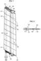
- an airfoil according to this embodiment comprises two aerodynamic profiles both adjustable in incidence and for which the relative camber angle is adjustable.
- they are called first flap or fore flap, and second flap or aft flap. They are designated by the references 100 and 200 respectively. They pivot on the axes defined by two masts 310, 320 as is going to be seen in the following.
- At least one of these profiles has an asymmetric aerodynamic transverse section in the fore-to-aft direction (with leading edge and trailing edge). It can for example involve sections called symmetric aircraft airfoil, and more preferably NACA 00xx standardized sections or others.
- the relative angle of the second flap relative to the first flap is differentially adjustable along the height thus allowing a washout of the second flap.
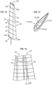
- FIGS 3A to 3D schematically show various positions which can be taken by the two flaps.
- the first flap 100 has in the present example one degree of freedom determined by pivoting about a longitudinal plane P of the airfoil (defined by an airfoil structure that is going to be described later), whereas the second flap 200 can be stressed using a sheet system, cylinder or any other system so as to take an inclination relative to the fore airfoil.
- Figure 3A shows a headwind (arrow F) position of the airfoil, with the aft flap 200 brought into the median position thereof.
- the fore flap 100 spontaneously orients according to the axis of the wind and here the aft flap is aligned therewith.
- the airflow (flow F1) along the windward side of the fore flap splits, in the area of the transition between the fore flap and the aft flap, between an inner flow F2a on the windward side of the aft flap and a flow F2b on the leeward side, which propagates through a vertical opening or slit L defined between the trailing edge 102 of the fore flap 100 and the leading edge 201 of the aft flap 200.
- the aft flap 200 has, because of a twist command that is going to be described in detail later, a difference between the inclination in the lower region 200' thereof compared to the plane P and the inclination of the upper region 200" thereof relative to the same plane P.
- the airfoil can be given a variable camber, which is helpful to improving the performance thereof. More specifically, with this variation an aerodynamic twist of the airfoil (variation of the null lift angle along the length) can be generated so as to either adapt to the wind gradient or to offload the top of the airfoil or even generate an inverse camber so as to increase a righting torque.
- the fore flap 100 is not free, but can be driven so as to adapt a behavior similar to that shown in Figures 3A to 3D .
- the angular interval within which the fore flap 100 is free to move is typically comprised between ⁇ 1° and ⁇ 15°.
- the airfoil comprises a rigid frame 300 formed by the two cylindrical masts 310 and 320, here the outside diameter is constant, rigidly connected to each other by respectively upper and lower transverse structural members 330, 340 respectively forming a boom member and a gaff member.
- This structural framework is free to turn on itself relative to the structure by bearings connecting it to the mainmast.
- the members of this structural frame are formed of parts, for example of metal or composite material, sized appropriately depending on the stresses.
- the fore mast 310 is self-bearing, meaning without shrouds, but it can of course be anticipated that it be equipped with all or part of the following members: shrouds, stays, running backstays, with attachment points at the top of the mast above the structure of the flaps.
- the aft mast 320 can have a smaller diameter than that of the fore mast 310.
- a series of fore shape members 110 and a series (preferably the same number) of aft shape members 210 are mounted respectively on the fore mast and aft mast; jointly the members describe an envelope of symmetric aerodynamic profiles intended to form, with respective envelopes 120, 220 (not shown in Figures 4 to 7 ) the first and second flaps 100, 200.
- envelopes 120, 220 are made for example in the form of taut coverings on the respective shape members.
- An aeronautical canvas or fabric of the type used for conventional sails, brought under tension during hoisting, can in particular be used.
- the envelopes 120, 220, or at least one of them can be discontinuous, i.e. made of two or several envelopes of lesser heights, substantially aligned along the respective flap and separated by gaps of limited height.
- the shape members 110, 210 are free in rotation and translation on their respective mast 310, 320. These two degrees of freedom are provided for example by smooth bearings or ball bearings (not shown in Figures 4 to 7 ), intended to allow these movements with reduced friction while avoiding risks of pinching.
- these bearings comprise two bearing members, respectively 112a, 112b, enclosed in the upper region and in the lower region of a shape member 110 while surrounding an opening 111 formed in said shape member to allow passage of the associated mast 310.
- the height of the guiding members is chosen to minimize friction and the risk of blocking while giving the airfoil the most compact form possible once dropped.
- the two airfoils can be hoisted and hauled down as will be seen in the following and can also be reefed.
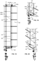
- the vertical displacement of the shape members 110, 210 and of the respective envelope 120, 220 thereof is done identically on the two masts by making the gaff part 340 in form of a fixed member 342 rigidly secured to the masts 310, 320 and an elevator member 344 capable of sliding along the masts and to which are secured with freedom of rotation the highest shape members (110a, 210a) of the fore airfoil 100 and the aft airfoil 200, where this sliding member 344 could be hoisted and lowered using a halyard 400 in that way driving each envelope and, progressively, each shape member respectively 110, 210.
- connection with freedom of rotation between the shape members 110a, 210a and the part 344 assures the secure connection in translation of the upper end of the airfoils with said part while also allowing the freedom of movement of the fore flap 100 relative to the gaff 340 within defined angular limits, as described in the preceding, and the freedom of movement of the aft flap 200 angularly urged in inclination by means of provisions that will be described in the following.
- the halyard 400 is guided by an assembly of transfer pulleys (including a pulley 410 on the top of the fixed member 342 of the gaff assembly 340) and passes through an opening formed in the central region of the fixed part 342 of the gaff 340 for being attached to the central region of the sliding part 344. From the upper region of the airfoil, the halyard 400 runs downward inside of the fore mast 310 after entering it through an opening 312 (see Figure 11 ). The lower end of the halyard (not visible) can be manipulated manually or, for the largest dimension airfoils, using a motor (not shown).
- the fore flap 100 has, as already said, some degree of angular freedom around the mast 310 thereof. It was however seen that in another embodiment, it could be controlled by a mainsheet or other control member.
- a lower angular stop can be provided by providing a finger 114 projecting from the lowest shape member 110b of the fore flap 100 that engages in a throat 332 arranged in a circular sector on the upper surface of the boom 330.
- a similar arrangement can be provided between the highest shape member 110a of the fore flap and the lower surface of the sliding member 344 of the gaff 340.
- a limit on the angular swing of the fore flap 100 can be provided by acting between the mast 310 and the lower shape member 110b (respectively the highest shape member 110a), or even by using a lanyard with one end attached in the aft region of the lowest shape member 110b and the other end on the boom 330.
- a corresponding arrangement is provided between the highest shape member 110a and the sliding member 344 of the gaff 340.
- an arrangement to restrict the angular mobility of the fore shape members 110 relative to the fore mast 310 comprises at least one longitudinal rib (in this example two opposed ribs 310c, 310d) provided on mast 310 and capable of cooperating with a pair of longitudinal recesses 110c, 110d of greater angular width formed in the bearing members 112a, 112b of the shape members 110.
- the ribs 310a, 310b can be integral with the masts or provided on skirts surrounding the respective mast bodies.
- a transverse rail can be provided secured to the boom 330 and in which a cart can slide following the aft region of the lowest formed member 110b and an equivalent (or different) arrangement can be provided in the upper region of the airfoil.
- the angular position of the base of the aft flap is progressively driven to in that way increase or decrease the camber of the airfoil, from one side or the other, depending on the wind and navigation conditions.
- a second cylinder 520 arranged generally symmetrically from the first cylinder is provided.
- the body of the cylinder is mounted with freedom of rotation on a plate 334 arranged opposite from the first plate 332.
- the rod of the cylinder 520 is mounted with articulation on a transfer member 525 mounted pivotably on the lower end of the mast 320 immediately below the boom member 330.
- This transfer member 525 is made as a single piece and forms two opposed transfer arms 525a, 525b arranged in a generally transverse direction relative to the boom, where the rod of cylinder 520 is connected to the free end of the first transfer arm 525a.
- Two transfer lanyards 610, 620 are attached in the region of the respective free ends of the two transfer arms 525a, 525b. These lanyards, with the help of appropriate transfer pulleys 611, 621, pass inside the fore mast 310 towards the top thereof, come out therefrom through the opening 312 provided for the halyard 400 and are connected there to a second transfer member 530 generally identical to the member 525 and arranged between the sliding member 344 of the gaff 340 and the highest shape member 210a by being secured in rotation with said shape member.
- a mechanism for adjustment of the length of the lanyards 610, 620 between their attachment points thereof on the respective transfer members 525, 530 thereof is provided.
- this adjustment can be done manually, for example near the lower transfer member 525 by means of jamming cleats.
- actuators for example electric, are provided with which to selectively release and retain lanyards in the area of said transfer member 525.
- the assembly formed by the rigid structure can be adjusted angularly (trimmed/slackened) about the axis of the craft by turning the fore mast 310 on itself.
- this rotation can be implemented by means of a hollow shaft motor with reduction gear (not shown) mounted at the base of the mast 310 coaxially therewith.
- a sheet and tackle can be simply provided analogously to the control of a traditional mainsail.
- the lashing is then done in the area of the aft region of the boom member 330.
- the members 330, 342 are mounted on the fore mast 310 so as to be secured therewith in rotation.
- a double-flap airfoil is thus proposed according to the present invention which allows automatically (without specific adjustment) benefiting from a slit effect between the fore flap and the aft flap.
- an airfoil according to the above disclosure can be made droppable and reefable extremely easily by means of a single halyard controlled manually or by motor.
- operation of the airfoil (general orientation, camber, variation of the camber) can be easily driven by means of actuators, and automated.
- Harken, Pewaukee, Wisconsin USA proposes automatic sail control systems which can be adapted to an airfoil according to the present invention by the person skilled in the art.
- each flap 100, 200 is made by telescopically nesting a series of generally rigid box type shape members, respectively 130, 230, each having (see Figure 13 ) a generally U-shaped vertical section with a bottom (respectively 131, 231) and a rising peripheral wall (respectively 132, 232), where each member is slightly smaller than the member located immediately below so as to be able, depending on the applied stresses, to occupy relative to it a released position or a position where it is enclosed in it.
- Other vertical sections allowing nesting of the members can be considered.
- the bottoms 131 of the shape members 130 each have an opening 133 through which the fore mast 310 extends.
- the bottoms 231 of the shape members 230 each have an opening 233 through which the aft mast 320 extends.
- these openings are provided with guiding rings or analogs, for example in a way similar to what is shown in Figure 8 concerning the shape members from the first embodiment.
- the masts 310, 320 serve as guides for the respective boxes in order to avoid pinching thereof during mutual movements thereof.
- two adjacent boxes are equipped with stop means (flanges, rims, fingers or others) so as to avoid one box becoming completely separated from the other.
- the lowest boxes 130a, 130b are secured in vertical translation to the boom member 330 whereas in the upper region of the airfoil, the highest boxes 130b, 230b are secured in vertical translation to the sliding member 344 of the gaff 340.
- displacement of the sliding member 344 by the halyard 400 serves to hoist the airfoil with the boxes from the fore airfoil and aft airfoil deploying progressively upward during this hoisting.
- Hauling down is done by inverse movements, the total height of the airfoil after dropping is substantially equal to the height of one box.
- reefing is possible by bringing the sliding member 344 to an intermediate height above the boom 330.
- variable camber of the airfoil achieved as was seen because of a twist of the aft flap 200, can be allowed here by making the boxes from a semi-rigid material allowing some degree of elastic deformation of the boxes between the bottom point thereof and the top point thereof. Alternatively or in addition to this arrangement, some play can be provided between the base of one box and the open upper end of the box located immediately below.
- the lower box 130b of the fore flap preferably has a freedom of movement in a preset angular range in the same way as the lowest shape member 110b of the fore flap 100 from the first embodiment.
- the upper box 130a of the fore flap also has this freedom in the same way as the highest shape member 110a of the fore flap 100 from the first embodiment.
- the lowest box 230b and the highest 230a of the aft flap 200 are urged in the same way as the lowest shape member 210b and the highest shape member 210a respectively of the aft flap 200 of the first embodiment.
- the fore mast 310 and the aft mast 320 preferably have a slight mutual inclination to keep a generally constant width of slit L between the fore flap and the aft flap despite progressive reduction of the transverse section of the flaps (inherent in their telescopic structure) from bottom to top.
- a mechanism can be provided for horizontal translation of the boxes over a short distance, once they are released from each other or during an end of range of the release movement, in order to at least approximately align the trailing edges of the fore flap and the leading edges of the aft flap, to in that way keep an essentially constant slit width.
- the flaps are constituted of one or more airtight envelopes inflatable by section or as a whole.
- the airfoils can be stiffened in the position thereof for use.
- the shape members 110, 210 can be adapted as a consequence, for example by constraining the respective airfoil section by ribs which then play the role of shape members.
- the shape members are then not sealed and are designed for allowing air to pass vertically along the flap.
- an aim of this embodiment is to offer the airfoil a capacity of independent controlling (manual or motorized), hoisting, hauling down and reefing of the fore flap and the aft flap, respectively, as particularly shown in Figures 25a and 25b , while keeping the possibility of twisting the aft flap.
- the fore and aft flaps can be independently controlled it terms of hoisting, hauling down and reefing by means of respective halyards 400A, 400B.
- Both halyards are of the loop type, i.e. without the need for furling.
- Halyard 400A for the fore flap 100 is driven by a first pulley 430A powered by a gearmotor 420A, both mounted on a support structure 440 at the base of the fore mast 310 (cf. Figure 22 ). From this gearmotor, halyard 400A travels inside the fore mast 310, exits from an opening provided with a pulley at the top of the fore mast and is directed to the top shape member 110a of the fore flap 100 via another pulley and an opening provided in the gaff 340. Halyard 400A is attached to said shape member 110a and, from there, travels along the fore mast, through a plurality of openings formed in the successive shape members 110 and ultimately 110b. From there it is redirected by appropriate pulleys around the boom and toward driving pulley 430A.
- Halyard 400B for the rear flap 200 is driven by a second pulley 430B powered by a gearmotor 420B and also travels inside the fore mast 310, and is then guided along the top of gaff member 340 and then downwardly inside said member. It is attached to the top shape member 210a of the aft flap and then continues through a plurality of openings formed in the successive shape members 210 and ultimately 210b. From there it redirected by appropriate pulleys around the boom and rearwardly, toward driving pulley 430B.
- the twisting is applied in this embodiment not to the top and bottom shape members 210a, 210b of the aft flap like in the first embodiment, but directly to the aft mast 320.
- the capacity of twisting of the mast itself can be ensured either by selecting a material for the mast body that can endure a given degree of twisting (typically an appropriate composite material), or by providing around the mast body an outer skirt that can slide around the mast body and can be subjected to twisting.
- a material for the mast body that can endure a given degree of twisting (typically an appropriate composite material)
- a given degree of twisting typically an appropriate composite material
- the twist control in a manner similar to the first embodiment, relies on a pair of cylinders 510, 520 arranged under the boom member 330.
- a first cylinder 510 is capable of driving the bottom of aft mast 320 through a first transfer plate 515 which, contrary to the first embodiment, is located below the boom member 330.
- Plate 515 is in direct connection with the bottom end of mast 320 which extends through the boom thickness, so as to induce a rotational movement thereof in a direction or the other.
- a second cylinder 520 is capable of driving the top of the aft mast 320 via a control plate 525 with control arms 525a, 525b connected to respective lanyards 610, 620 (not shown in Figure 20 ), much like in the first embodiment.
- transfer plate 530 which is provided with similar transfer arms 530a, 530b and which is rigidly connected (at least rotationwise) with the top of the aft mast.
- a twisting of the aft flap can be provided in addition to this orientation control.
- the angular control of the bottom and top regions of the aft mast 320 can be performed by means of respective motors acting of the respective mast regions through direct drive or through appropriate gearing.
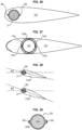
- Figure 26 shows that the mast 320 has a constant, non-circular cross-section, with two diametrally opposed, longitudinal ribs 325 extending along the full height of the mast.
- Each of the shape members 210 has (preferably in a bearing part or portion thereof) an aperture 211 of a complementary shape, with two diametrally opposed recesses 215 in which engage the respective ribs 325. In this manner the shape members 210 and the aft mast 320 are locked together rotationwise, while allowing the shape members 210 to slide along the mast for hoisting, hauling down and reefing purposes.
- Figure 29 illustrate a variant embodiment of the mast 320, which comprises a main mast body 320a surrounded by a skirt or sleeve 320b which can freely rotate around body 320a.
- the material properties and the thickness of the sleeve 320b allow finely tuning the twisting properties thereof, so as to achieve the same aft flap twisting as described above while keeping a main mast body 320a of suitable rigidity.
- each flap or one of the flaps (typically the aft flap) be realized in several parts such that the angular offset of each part relative to those nearby serves to make a washout in particular in the area of the rear flap.
- one airfoil with two flaps according to the invention can advantageously equip any type of craft: leisure boats, dinghies or light multihulls, racing boats, container ships for achieving fuel savings, mixed motorized and sail propulsion cruise ships, etc.
Landscapes
- Engineering & Computer Science (AREA)
- Life Sciences & Earth Sciences (AREA)
- Sustainable Development (AREA)
- Sustainable Energy (AREA)
- Chemical & Material Sciences (AREA)
- Combustion & Propulsion (AREA)
- Mechanical Engineering (AREA)
- Ocean & Marine Engineering (AREA)
- Wind Motors (AREA)
- Jib Cranes (AREA)
Claims (9)
- Tragflügel, der eine Struktur und einen an der Struktur (300) montierten Doppeltragflügel (100, 200) umfasst, wobei die Struktur abhängig von den Bedingungen winkelmäßig um eine im Allgemeinen vertikale Achse gesteuert wird, wobei der Doppeltragflügel eine vordere Klappe (100) und eine hintere Klappe (200) umfasst, von denen mindestens eine eine Asymmetrie von vorne nach hinten aufweist und die durch einen Schlitz (L) getrennt sind, wobei jede Klappe eine Reihe von in der Höhe verteilten Formelementen (110; 210) umfasst, wobei die Struktur einen vorderen Mast (310) und einen hinteren Mast (320) umfasst, die durch ein Auslegerelement (330) und ein Gaffelelement (340) verbunden sind, wobei die Formelemente (110) der vordere Klappe vom vorderen Mast (310) durchquert werden, während sie gleichzeitig um eine dadurch definierte Achse geschwenkt werden können, wobei die Formelemente (120) der hinteren Klappe vom hinteren Mast (320) durchquert werden, während sie gleichzeitig um eine dadurch definierte Achse geschwenkt werden können, und wobei sich die Struktur um eine durch den vorderen Mast (310) gebildete Drehachse schwenken kann, wobei die vordere Klappe und die hintere Klappe (100, 200) jeweils ein oberes Element (110a; 210a) umfassen, die unabhängig voneinander entlang seines jeweiligen Masts (310; 320) gleiten können, wobei der Tragflügel ferner ein Fall (400), mit dem die vordere und die hintere Klappe zusammen gehisst, niedergeholt und gerefft werden können, oder zwei Fallen (400A, 400B) umfasst, mit denen die vordere und die hintere Klappe unabhängig voneinander gehisst, niedergeholt und gerefft werden können, und wobei der vordere Mast und die zugehörigen vorderen Formelemente eine zusammenwirkende Anordnung aus Längsrippen und Aussparungen (310c, 310d, 110c, 110d) umfasst, bei der die Aussparungen (110c, 110d) eine größere Winkelbreite als die Rippen (310c, 310d) aufweisen, um die Winkelverschiebung der vorderen Formelemente im Verhältnis zum vorderen Mast zu begrenzen, während den vorderen Formelementen ermöglicht wird, entlang des vorderen Masts zu gleiten.
- Tragflügel nach Anspruch 1, wobei der hintere Mast (320) eine Anordnung umfasst, um die zugehörigen Formelemente (210) winkelmäßig an dem Mast zu arretieren, während den Formelementen gleichzeitig ermöglicht wird, entlang des Masts zu gleiten.
- Tragflügel nach einem der Ansprüche 1 und 2, wobei die zusammenwirkende Anordnung aus Rippen und Aussparungen oder die zusammenwirkenden Anordnungen aus Rippen und Aussparungen mindestens eine Rippe (310c, 310d) am entsprechenden Mast und eine entsprechende Aussparung (110c, 110d) an jedem dem entsprechenden Mast zugehörigen Formelement (110) umfassen.
- Tragflügel nach Anspruch 3, wobei die zusammenwirkende Anordnung aus Rippen und Aussparungen oder die zusammenwirkenden Anordnungen aus Rippen und Aussparungen zwei entgegengesetzte Längsrippen (310c, 310d) am entsprechenden Mast und zwei entsprechende Aussparungen (110c, 110d) am jeden dem entsprechenden Mast zugehörigen Formelement (110) umfassen.
- Tragflügel nach Anspruch 2, wobei der hintere Mast (320) drehbar ist und die Steuerung auf die Unterseite und die Oberseite des hinteren Mast einwirken kann.
- Tragflügel nach Anspruch 1 bis 6, die unabhängige Antriebsanordnungen (420A, 430A; 420B, 430B) für die beiden Fallen (400A, 400B) umfasst, mit denen die vordere und die hintere Klappe unabhängig voneinander gehisst, niedergeholt und gerefft werden können.
- Tragflügel nach Anspruch 6, wobei die Antriebsanordnungen an einer Trägerstruktur (440) an der Basis des vorderen Masts (310) montiert sind.
- Tragflügel nach Anspruch 7, wobei die beiden Fallen so angeordnet sind, dass sie sich entlang des vorderen Masts (310) oder in diesem bewegen.
- Tragflügel nach einem der Ansprüche 1 bis 8, wobei die beiden Fallen (400A, 400B) geschlungen sind, wodurch ein Einrollen verhindert wird.
Applications Claiming Priority (2)
| Application Number | Priority Date | Filing Date | Title |
|---|---|---|---|
| US201816307880A | 2018-12-06 | 2018-12-06 | |
| PCT/IB2019/060529 WO2020115717A1 (en) | 2018-12-06 | 2019-12-06 | Ship with sail propulsion |
Publications (3)
| Publication Number | Publication Date |
|---|---|
| EP3891063A1 EP3891063A1 (de) | 2021-10-13 |
| EP3891063B1 true EP3891063B1 (de) | 2025-04-23 |
| EP3891063C0 EP3891063C0 (de) | 2025-04-23 |
Family
ID=69185627
Family Applications (1)
| Application Number | Title | Priority Date | Filing Date |
|---|---|---|---|
| EP19839664.0A Active EP3891063B1 (de) | 2018-12-06 | 2019-12-06 | Schiff mit segelantrieb |
Country Status (7)
| Country | Link |
|---|---|
| US (1) | US11891160B2 (de) |
| EP (1) | EP3891063B1 (de) |
| JP (1) | JP2022510414A (de) |
| KR (1) | KR102844962B1 (de) |
| CN (1) | CN113302125B (de) |
| CA (1) | CA3122056A1 (de) |
| WO (1) | WO2020115717A1 (de) |
Families Citing this family (13)
| Publication number | Priority date | Publication date | Assignee | Title |
|---|---|---|---|---|
| US20240227999A1 (en) * | 2017-11-06 | 2024-07-11 | Ayro | Ship with sail propulsion |
| IT202100014684A1 (it) * | 2021-06-07 | 2022-12-07 | Giorgio Cubeddu | Ala asimmetrica sezionale a curvatura invertibile |
| CN113998087B (zh) * | 2021-11-19 | 2023-02-24 | 武汉理工大学 | 一种船舶翼形抗横倾装置 |
| FR3131269A1 (fr) | 2021-12-23 | 2023-06-30 | Ayro | Navire avec au moins un propulseur vélique |
| FR3131270A1 (fr) | 2021-12-23 | 2023-06-30 | Ayro | Unité de propulsion vélique, et navire comportant une telle unité |
| FR3131268B1 (fr) | 2021-12-23 | 2024-01-05 | Ayro | Unité de propulsion vélique, et navire comportant une telle unité |
| GB202119051D0 (en) * | 2021-12-28 | 2022-02-09 | Gt Green Tech Limited | Wingsail and method of use |
| GB2628740B (en) | 2021-12-28 | 2025-02-19 | Gt Green Tech Limited | Wingsail and method |
| CN114838022B (zh) * | 2022-03-31 | 2026-01-16 | 武汉船用机械有限责任公司 | 一种风帆驱动液压控制系统 |
| FR3142171A1 (fr) * | 2022-11-23 | 2024-05-24 | Philippe MARCOVICH | Système d’aile profilée |
| IT202300020757A1 (it) * | 2023-10-06 | 2025-04-06 | Aldo Cichero | Gruppo velico a sezioni rigide manovrabili telescopicamente |
| FR3161895A1 (fr) | 2024-05-02 | 2025-11-07 | Oceanwings | Dispositif de propulsion vélique |
| FR3165238A1 (fr) | 2024-08-02 | 2026-02-06 | Oceanwings | Dispositif de propulsion vélique |
Family Cites Families (43)
| Publication number | Priority date | Publication date | Assignee | Title |
|---|---|---|---|---|
| US2484687A (en) | 1945-08-30 | 1949-10-11 | Jr William P Carl | Rigid sail construction for boats or the like |
| US3332383A (en) | 1965-06-24 | 1967-07-25 | Wright Edward Morris | Variable camber airfoil |
| FR2499052B1 (fr) | 1981-02-04 | 1985-07-12 | Sopelem | Mecanisme de hissage et affalage d'un mat mobile en rotation |
| US4388888A (en) * | 1981-04-24 | 1983-06-21 | Gushurst Jr Fred W | Adjustable airfoil |
| DE3149838C2 (de) | 1981-12-16 | 1984-08-09 | Friedrich 2251 Pellworm Lucht | Segel mit Lufthülle und Formteilen zur Profilierung |
| US4437426A (en) | 1981-12-21 | 1984-03-20 | Fiberglass Unlimited, Inc. | Wing type air foil assembly |
| US4561374A (en) * | 1983-09-23 | 1985-12-31 | Asker Gunnar C F | Wind ship propulsion system |
| US4649848A (en) | 1984-03-20 | 1987-03-17 | Belvedere Mark S | Flexible wing rib sail |
| FR2567098B1 (fr) | 1984-07-05 | 1987-07-10 | Graveline Jean | Dispositif aerodynamique a concavite reversible, souple et affalable, pour la propulsion par la force du vent |
| EP0198065A1 (de) | 1984-10-17 | 1986-10-22 | CROWELL, Robert Lee | Drachensegelfahrzeug |
| US4685410A (en) * | 1985-04-08 | 1987-08-11 | Fuller Robert R | Wing sail |
| KR940000045B1 (ko) | 1985-05-02 | 1994-01-05 | 쟝 마가렛 워커 | 날개형 돛 장치 |
| GB8803265D0 (en) | 1988-02-12 | 1988-03-09 | Walker J G | Wingsail stalling |
| US4848258A (en) * | 1986-04-23 | 1989-07-18 | Priebe Paul D | Airfoil sailing system |
| FR2617117B1 (fr) | 1987-01-29 | 1992-02-07 | Orange Christian | Procede de propulsion de vehicules par le vent a l'aide d'une voilure faite d'elements rigides a profil aerodynamique symetrique |
| FR2643329A1 (fr) | 1988-10-04 | 1990-08-24 | Mapiani Antoine | Voile universelle automatique |
| US4895091A (en) | 1988-10-17 | 1990-01-23 | Elmali Nuri E | Reversible camber line flexible wing sail |
| IT1231705B (it) * | 1989-09-15 | 1991-12-20 | Giorgio Magrini | Struttura di vela cosidetta ad ala. |
| US5485799A (en) | 1991-04-17 | 1996-01-23 | Julien; Pierre | Device with at least one variable-geometry aerodynamic member including a boundary layer control system |
| US5313905A (en) | 1991-05-09 | 1994-05-24 | Calderon Albert A | Twin wing sailing yacht |
| US5540406A (en) | 1993-10-25 | 1996-07-30 | Occhipinti; Anthony C. | Hydrofoils and airfoils |
| US5517940A (en) | 1995-05-08 | 1996-05-21 | Beyer; Jay R. | Variable width multi-hulled boat with telescoping mast |
| DE19614150A1 (de) | 1996-04-10 | 1996-10-24 | Horst Stampe | Inmast Doppel-Rollreff-Rigg |
| US5868092A (en) | 1997-06-24 | 1999-02-09 | Milidragovic; Mladen | Wing sail and method of use |
| FR2771705A1 (fr) | 1997-11-28 | 1999-06-04 | Arnaud Ballu | Greement pour engin a propulsion velique |
| GB9800021D0 (en) | 1998-01-05 | 1998-03-04 | Advanced Design & Prototyping | Apparatus for sails |
| US6431100B2 (en) | 2000-03-24 | 2002-08-13 | Charles Allen Abshier | Stowable semi-rigid wing sail system |
| ITMI20031888A1 (it) | 2003-10-02 | 2005-04-03 | Ezio Morandi | Sistemi di vela alare a profilo variabile per imbarcazioni a vela. |
| US7574972B1 (en) | 2007-04-10 | 2009-08-18 | Gordon Fairchild | Three-dimensional sail apparatus |
| ES2311399B1 (es) | 2007-04-27 | 2009-12-04 | Ignacio Bermudez Sanchez | Vela rigida de perfil configurable. |
| GB0813202D0 (en) | 2008-07-18 | 2008-08-27 | Barron Michael | Sail arrangements and reconfigurable aerodynamic arrangements |
| ES2372831B1 (es) | 2009-03-16 | 2013-02-15 | José Miguel Bermúdez Miquel | Conjunto de velas rigidas abatibles, emparejadas y opuestas. |
| JP5318008B2 (ja) | 2010-03-19 | 2013-10-16 | 株式会社大内海洋コンサルタント | 帆走船 |
| IT1401595B1 (it) | 2010-08-12 | 2013-07-26 | Nautigest S R L | Struttura di vela a profilo alare, o wingsail , perfezionata. |
| US9308979B2 (en) | 2012-03-06 | 2016-04-12 | Stanislav Mostoviy | Reversible camber soft wing sail |
| US8635966B2 (en) | 2012-03-24 | 2014-01-28 | Helmuth G. Bachmann | Laminar air flow slot venting for sails |
| KR20130138921A (ko) * | 2012-06-12 | 2013-12-20 | 삼성중공업 주식회사 | 선박용 풍력 추진 장치 및 이를 포함하는 선박 |
| CN103523195B (zh) * | 2013-10-23 | 2016-01-20 | 芜湖特源鑫复合材料科技有限公司 | 一种遥控帆船 |
| ES2586128B1 (es) | 2015-03-10 | 2017-07-25 | Bound 4 Blue, S.L. | Vela de perfil variable |
| CN104925241B (zh) * | 2015-06-11 | 2017-06-23 | 江苏科技大学 | 一种可收缩式双尾襟翼翼型风帆 |
| CN104890845B (zh) * | 2015-06-23 | 2017-04-05 | 江苏科技大学 | 横向可折叠自动收放翼型帆 |
| GB201616255D0 (en) * | 2016-09-25 | 2016-11-09 | Magnan Charles R | Deployable framed wingsail |
| FR3058386B1 (fr) * | 2016-11-08 | 2019-06-28 | Ayro | Navire a propulsion velique. |
-
2019
- 2019-12-06 CN CN201980087613.4A patent/CN113302125B/zh active Active
- 2019-12-06 US US17/311,178 patent/US11891160B2/en active Active
- 2019-12-06 EP EP19839664.0A patent/EP3891063B1/de active Active
- 2019-12-06 JP JP2021531797A patent/JP2022510414A/ja active Pending
- 2019-12-06 CA CA3122056A patent/CA3122056A1/en active Pending
- 2019-12-06 WO PCT/IB2019/060529 patent/WO2020115717A1/en not_active Ceased
- 2019-12-06 KR KR1020217021063A patent/KR102844962B1/ko active Active
Also Published As
| Publication number | Publication date |
|---|---|
| US11891160B2 (en) | 2024-02-06 |
| EP3891063A1 (de) | 2021-10-13 |
| JP2022510414A (ja) | 2022-01-26 |
| KR102844962B1 (ko) | 2025-08-12 |
| WO2020115717A1 (en) | 2020-06-11 |
| CA3122056A1 (en) | 2020-06-11 |
| EP3891063C0 (de) | 2025-04-23 |
| CN113302125B (zh) | 2024-06-11 |
| US20220033044A1 (en) | 2022-02-03 |
| KR20210100154A (ko) | 2021-08-13 |
| CN113302125A (zh) | 2021-08-24 |
Similar Documents
| Publication | Publication Date | Title |
|---|---|---|
| EP3891063B1 (de) | Schiff mit segelantrieb | |
| US10906620B2 (en) | Ship with sail propulsion | |
| US4388888A (en) | Adjustable airfoil | |
| US8776708B2 (en) | Mechanised device for rigging a sail | |
| US5197401A (en) | Rotating ring mast sailing vessel and a method of vessel operation | |
| EP3052379B1 (de) | Verfahren zur handhabung und steuerung von profilsegeln | |
| AU2014331535A1 (en) | Method for rigging and controlling a wing sail | |
| US20240227999A1 (en) | Ship with sail propulsion | |
| GB2085387A (en) | Sails | |
| US6863008B2 (en) | Flexible wing-sail and wind-propelled vehicle including same | |
| EP0319591A1 (de) | Segelboot | |
| US4708075A (en) | Multi-hull sailboat with fixed airfoils | |
| CA1279529C (en) | Swing sail boat | |
| US12473062B1 (en) | Reversible camber wingsail | |
| EP4382410A1 (de) | Flügelstruktur für windunterstützten antrieb eines wasserfahrzeugs | |
| US8739720B2 (en) | Storable, sickle-shaped sailboat mast | |
| JP2024522097A (ja) | セール推進要素、セール推進式移動体 | |
| WO2025244551A1 (ru) | Парусная система и способ эксплуатации парусной системы | |
| NZ719265B2 (en) | Method for rigging and controlling a wing sail | |
| WO2012094731A1 (en) | Microairfoil and method for rigging and control |
Legal Events
| Date | Code | Title | Description |
|---|---|---|---|
| STAA | Information on the status of an ep patent application or granted ep patent |
Free format text: STATUS: UNKNOWN |
|
| STAA | Information on the status of an ep patent application or granted ep patent |
Free format text: STATUS: THE INTERNATIONAL PUBLICATION HAS BEEN MADE |
|
| PUAI | Public reference made under article 153(3) epc to a published international application that has entered the european phase |
Free format text: ORIGINAL CODE: 0009012 |
|
| STAA | Information on the status of an ep patent application or granted ep patent |
Free format text: STATUS: REQUEST FOR EXAMINATION WAS MADE |
|
| 17P | Request for examination filed |
Effective date: 20210706 |
|
| AK | Designated contracting states |
Kind code of ref document: A1 Designated state(s): AL AT BE BG CH CY CZ DE DK EE ES FI FR GB GR HR HU IE IS IT LI LT LU LV MC MK MT NL NO PL PT RO RS SE SI SK SM TR |
|
| DAV | Request for validation of the european patent (deleted) | ||
| DAX | Request for extension of the european patent (deleted) | ||
| STAA | Information on the status of an ep patent application or granted ep patent |
Free format text: STATUS: EXAMINATION IS IN PROGRESS |
|
| 17Q | First examination report despatched |
Effective date: 20230704 |
|
| GRAP | Despatch of communication of intention to grant a patent |
Free format text: ORIGINAL CODE: EPIDOSNIGR1 |
|
| STAA | Information on the status of an ep patent application or granted ep patent |
Free format text: STATUS: GRANT OF PATENT IS INTENDED |
|
| INTG | Intention to grant announced |
Effective date: 20241114 |
|
| GRAS | Grant fee paid |
Free format text: ORIGINAL CODE: EPIDOSNIGR3 |
|
| GRAA | (expected) grant |
Free format text: ORIGINAL CODE: 0009210 |
|
| STAA | Information on the status of an ep patent application or granted ep patent |
Free format text: STATUS: THE PATENT HAS BEEN GRANTED |
|
| RAP3 | Party data changed (applicant data changed or rights of an application transferred) |
Owner name: OCEANWINGS |
|
| AK | Designated contracting states |
Kind code of ref document: B1 Designated state(s): AL AT BE BG CH CY CZ DE DK EE ES FI FR GB GR HR HU IE IS IT LI LT LU LV MC MK MT NL NO PL PT RO RS SE SI SK SM TR |
|
| REG | Reference to a national code |
Ref country code: GB Ref legal event code: FG4D |
|
| REG | Reference to a national code |
Ref country code: CH Ref legal event code: EP |
|
| REG | Reference to a national code |
Ref country code: DE Ref legal event code: R096 Ref document number: 602019069095 Country of ref document: DE |
|
| REG | Reference to a national code |
Ref country code: IE Ref legal event code: FG4D |
|
| U01 | Request for unitary effect filed |
Effective date: 20250515 |
|
| U07 | Unitary effect registered |
Designated state(s): AT BE BG DE DK EE FI FR IT LT LU LV MT NL PT RO SE SI Effective date: 20250521 |
|
| PG25 | Lapsed in a contracting state [announced via postgrant information from national office to epo] |
Ref country code: ES Free format text: LAPSE BECAUSE OF FAILURE TO SUBMIT A TRANSLATION OF THE DESCRIPTION OR TO PAY THE FEE WITHIN THE PRESCRIBED TIME-LIMIT Effective date: 20250423 |
|
| PG25 | Lapsed in a contracting state [announced via postgrant information from national office to epo] |
Ref country code: NO Free format text: LAPSE BECAUSE OF FAILURE TO SUBMIT A TRANSLATION OF THE DESCRIPTION OR TO PAY THE FEE WITHIN THE PRESCRIBED TIME-LIMIT Effective date: 20250723 Ref country code: GR Free format text: LAPSE BECAUSE OF FAILURE TO SUBMIT A TRANSLATION OF THE DESCRIPTION OR TO PAY THE FEE WITHIN THE PRESCRIBED TIME-LIMIT Effective date: 20250724 |
|
| PG25 | Lapsed in a contracting state [announced via postgrant information from national office to epo] |
Ref country code: PL Free format text: LAPSE BECAUSE OF FAILURE TO SUBMIT A TRANSLATION OF THE DESCRIPTION OR TO PAY THE FEE WITHIN THE PRESCRIBED TIME-LIMIT Effective date: 20250423 |
|
| PG25 | Lapsed in a contracting state [announced via postgrant information from national office to epo] |
Ref country code: HR Free format text: LAPSE BECAUSE OF FAILURE TO SUBMIT A TRANSLATION OF THE DESCRIPTION OR TO PAY THE FEE WITHIN THE PRESCRIBED TIME-LIMIT Effective date: 20250423 |
|
| PG25 | Lapsed in a contracting state [announced via postgrant information from national office to epo] |
Ref country code: RS Free format text: LAPSE BECAUSE OF FAILURE TO SUBMIT A TRANSLATION OF THE DESCRIPTION OR TO PAY THE FEE WITHIN THE PRESCRIBED TIME-LIMIT Effective date: 20250723 |
|
| PG25 | Lapsed in a contracting state [announced via postgrant information from national office to epo] |
Ref country code: IS Free format text: LAPSE BECAUSE OF FAILURE TO SUBMIT A TRANSLATION OF THE DESCRIPTION OR TO PAY THE FEE WITHIN THE PRESCRIBED TIME-LIMIT Effective date: 20250823 |
|
| PGFP | Annual fee paid to national office [announced via postgrant information from national office to epo] |
Ref country code: GB Payment date: 20251226 Year of fee payment: 7 |
|
| PG25 | Lapsed in a contracting state [announced via postgrant information from national office to epo] |
Ref country code: SM Free format text: LAPSE BECAUSE OF FAILURE TO SUBMIT A TRANSLATION OF THE DESCRIPTION OR TO PAY THE FEE WITHIN THE PRESCRIBED TIME-LIMIT Effective date: 20250423 |
|
| U20 | Renewal fee for the european patent with unitary effect paid |
Year of fee payment: 7 Effective date: 20251211 |
|
| PG25 | Lapsed in a contracting state [announced via postgrant information from national office to epo] |
Ref country code: CZ Free format text: LAPSE BECAUSE OF FAILURE TO SUBMIT A TRANSLATION OF THE DESCRIPTION OR TO PAY THE FEE WITHIN THE PRESCRIBED TIME-LIMIT Effective date: 20250423 |
|
| PG25 | Lapsed in a contracting state [announced via postgrant information from national office to epo] |
Ref country code: SK Free format text: LAPSE BECAUSE OF FAILURE TO SUBMIT A TRANSLATION OF THE DESCRIPTION OR TO PAY THE FEE WITHIN THE PRESCRIBED TIME-LIMIT Effective date: 20250423 |
|
| PLBE | No opposition filed within time limit |
Free format text: ORIGINAL CODE: 0009261 |
|
| STAA | Information on the status of an ep patent application or granted ep patent |
Free format text: STATUS: NO OPPOSITION FILED WITHIN TIME LIMIT |
|
| REG | Reference to a national code |
Ref country code: CH Ref legal event code: L10 Free format text: ST27 STATUS EVENT CODE: U-0-0-L10-L00 (AS PROVIDED BY THE NATIONAL OFFICE) Effective date: 20260304 |
|
| 26N | No opposition filed |
Effective date: 20260126 |