EP3891105B1 - Système et procédé de séparation de suspensions - Google Patents
Système et procédé de séparation de suspensions Download PDFInfo
- Publication number
- EP3891105B1 EP3891105B1 EP19808799.1A EP19808799A EP3891105B1 EP 3891105 B1 EP3891105 B1 EP 3891105B1 EP 19808799 A EP19808799 A EP 19808799A EP 3891105 B1 EP3891105 B1 EP 3891105B1
- Authority
- EP
- European Patent Office
- Prior art keywords
- perforated plate
- filter
- surface filter
- sludge
- sedimentation tank
- Prior art date
- Legal status (The legal status is an assumption and is not a legal conclusion. Google has not performed a legal analysis and makes no representation as to the accuracy of the status listed.)
- Active
Links
Images


Classifications
-
- C—CHEMISTRY; METALLURGY
- C02—TREATMENT OF WATER, WASTE WATER, SEWAGE, OR SLUDGE
- C02F—TREATMENT OF WATER, WASTE WATER, SEWAGE, OR SLUDGE
- C02F11/00—Treatment of sludge; Devices therefor
- C02F11/12—Treatment of sludge; Devices therefor by de-watering, drying or thickening
- C02F11/121—Treatment of sludge; Devices therefor by de-watering, drying or thickening by mechanical de-watering
-
- C—CHEMISTRY; METALLURGY
- C02—TREATMENT OF WATER, WASTE WATER, SEWAGE, OR SLUDGE
- C02F—TREATMENT OF WATER, WASTE WATER, SEWAGE, OR SLUDGE
- C02F1/00—Treatment of water, waste water, or sewage
- C02F1/28—Treatment of water, waste water, or sewage by sorption
- C02F1/286—Treatment of water, waste water, or sewage by sorption using natural organic sorbents or derivatives thereof
-
- C—CHEMISTRY; METALLURGY
- C02—TREATMENT OF WATER, WASTE WATER, SEWAGE, OR SLUDGE
- C02F—TREATMENT OF WATER, WASTE WATER, SEWAGE, OR SLUDGE
- C02F2303/00—Specific treatment goals
- C02F2303/16—Regeneration of sorbents, filters
-
- Y—GENERAL TAGGING OF NEW TECHNOLOGICAL DEVELOPMENTS; GENERAL TAGGING OF CROSS-SECTIONAL TECHNOLOGIES SPANNING OVER SEVERAL SECTIONS OF THE IPC; TECHNICAL SUBJECTS COVERED BY FORMER USPC CROSS-REFERENCE ART COLLECTIONS [XRACs] AND DIGESTS
- Y02—TECHNOLOGIES OR APPLICATIONS FOR MITIGATION OR ADAPTATION AGAINST CLIMATE CHANGE
- Y02E—REDUCTION OF GREENHOUSE GAS [GHG] EMISSIONS, RELATED TO ENERGY GENERATION, TRANSMISSION OR DISTRIBUTION
- Y02E50/00—Technologies for the production of fuel of non-fossil origin
- Y02E50/30—Fuel from waste, e.g. synthetic alcohol or diesel
Definitions
- the invention relates to a device according to claim 1 and a method according to claim 8.
- a device for separating suspensions with a sedimentation tank in which a surface filter is immersed in the suspension is known, for example, from US 6 500 344 B1
- the surface filter is stationary and driven in rotation.
- suspension is a heterogeneous mixture of a liquid and undissolved, finely distributed solid particles. Mixtures of substances are often heterogeneous or multi-phase and are then also referred to as dispersions.
- Heterogeneous mixtures can be separated using mechanical methods.
- the simplest method for separating suspensions is sedimentation. When the solids settle, two phases are obtained, and the liquid can then be separated as the supernatant, for example by decanting.
- the sedimentation rate depends on the viscosity of the liquid, the size of the solid particles and the density of the particles, which is why this separation process can be very time-consuming.
- Large tanks are used for sedimentation. These are called clarifiers or thickeners, depending on whether you want to extract the liquid or the solid.
- the separation speed can be significantly accelerated.
- Another form of surface filtration is cross-flow filtration.
- the medium to be filtered is guided parallel to the filter, which prevents the formation of a filter cake.
- the solids are not completely freed from the liquid, but are only thickened.
- the filter centrifuge is a combination of centrifugation and filtration. Another separation process is flotation. Hydrophobic particles adhere particularly well to gas bubbles, which causes them to buoyant and then float on the surface of the liquid as foam (flotation), which can be used to remove the solids.
- Possible suspensions include sewage sludge (primary sludge, secondary sludge, mixed sludge, digested sludge), raw liquid manure or slurry and/or fermentation residues from biogas plants, suspended waste and by-products from the food industry or water-rich solid-liquid mixtures with organic components, which are created, among other things, by eutrophication in lakes, ponds, rivers and on sea coasts.
- sewage sludge primary sludge, secondary sludge, mixed sludge, digested sludge
- raw liquid manure or slurry and/or fermentation residues from biogas plants suspended waste and by-products from the food industry or water-rich solid-liquid mixtures with organic components, which are created, among other things, by eutrophication in lakes, ponds, rivers and on sea coasts.
- Sewage sludge is a suspension that is very rich in water and low in solids (e.g. excess sludge: 6 - 8 kg dry residue per m 3 ).
- volume reduction is a necessary prerequisite for economical and climate-friendly sludge treatment.
- more than half of the municipal sewage treatment plants in Germany carried out no thickening or only static thickening.
- liquid manure i.e. liquid manure, liquid slurry or liquid digestate from biogas plants
- a reduction in volume directly reduces disposal costs, which are often dominated by the proportionate transport costs.
- Eutrophication in lakes, ponds, rivers and on sea coasts can lead to increased growth of algae or micro-plants. Increased separation of organic solids from the water can remove nutrients bound in the organic matter from the water. Eutrophication effects, such as increased oxygen consumption, are reduced. Thickening of algae from breeding facilities in preparation for further treatment is also an application.
- Sewage sludge that is produced in municipal or industrial wastewater treatment can be statically thickened. This is a frequently used and simple thickening process.
- stationary thickeners or continuous thickeners solids enrichment in the lower part of the thickener occurs through sedimentation. The solids content in the lower part of the thickener generally increases.
- stationary thickeners sludge is fed in discontinuously. Sedimentation usually takes place within a day. After sedimentation has been completed, the supernatant sludge water (turbid water) has been separated, which can then be drained off. The thickened sewage sludge is then drained off. In some applications, the process is also carried out in the reverse order.
- Manual devices for removing sludge water include telescopic pipes, floating extraction devices or step drains. Direct observation by the operating personnel is necessary in order to visually recognize the transition from the turbid water phase to the sludge phase.
- the sludge inflow, sludge water outflow and the removal of the thickened sewage sludge take place (quasi-) continuously.
- the sludge is usually fed in via a central middle structure in the upper sludge water zone.
- the solid particles sediment in the basin, with the sludge water rising to the top and running off via discharge channels behind upstream baffles on the circumference of the thickener.
- the removal of the thickened sewage sludge takes place at the point with the highest thickening - the funnel tip.
- Mechanical thickening units usually use artificial gravity fields to free previously chemically conditioned sewage sludge from the sludge water. Separation takes place using sieve cloths and sieve plates. Most units require the use of polymer flocculants (pFM) to reduce the water-binding capacity of the sludge suspension in advance through conditioning.
- pFM polymer flocculants
- Another method for mechanically separating suspended and floating matter is flotation.
- By injecting gas bubbles into the suspension particles adhere to floating gas bubbles and achieve solid-liquid separation by floating up and then removing the flotate.
- a bottom scraper is usually also provided to prevent the tank from becoming silted up.
- the addition of chemicals (foamers) may be necessary to increase the degree of separation. In this method, no separation takes place via a filter.
- Suspensions can also be thickened in containers with a separating sieve or in (filter) bags made of sieve cloth.
- a separating sieve or in (filter) bags made of sieve cloth.
- Stationary thickeners are usually designed in duplicate or triplicate and, after being filled one after the other, are left to stand for around 24 hours in order to carry out the decanting process after the solids have settled.
- the sludge is fed into very steeply designed funnel tips (minimum gradient 1.5:1).
- the thickening volume is designed for residence times (HRT) of usually 1 to 2 days.
- Continuous thickeners, settling tanks with a similar structure to primary and secondary clarifiers are also designed for a residence time of 1 to 2 days.
- Continuous thickeners are (quasi-)continuously flowed through and the settling process of the solids is positively influenced by a scraper and rake mechanism.
- the thickened sludge is drawn off from a funnel tip in the middle of the tank, similar to the stationary thickeners.
- the quality of the sludge water discharge is crucial. Static thickening has the disadvantage that preferably only clearly defined sludge water layers can be discharged, because otherwise the sludge water returned to the wastewater treatment plant leads to increased cleaning effort in the biological stage of wastewater treatment.
- the free sludge water in the consolidation layers cannot be separated without also removing the solids it contains.
- When draining the thickened sludge if the discharge speed is too high, there is a risk of duckweed or water funnels forming before the sludge water is separated, which cause the drained sludge to mix with turbid water. There is also a fundamental risk that sludge will be stirred up and discharged. It is very important to separate sludge water with as few solids as possible so that the biological stage of wastewater treatment is not burdened too much.
- the WO 2004/005201 A1 discloses a method and apparatus for conveying sludge from a wastewater treatment plant into a dewatering and composting tank, wherein sludge and/or thick matter from different sources are fed to the bottom area of a dewatering and composting tank so that the residual water seeps downwards while the upper area of the solid matter is increasingly dried out and composted.
- a filter system is known in which round surface filters are used. Nets or fabrics are used as filter elements, on the outside of which mud adheres, which can be pushed out from the inside by means of overpressure.
- a device and a method for separating suspensions described above are to be improved so that the separation of sewage sludge into the phases sludge water (liquid) and sludge (solids) is carried out more effectively.
- a generic device is characterized in that at least one tube extending in an axial direction is inserted between the outer perforated plate and the inner perforated plate, the wall of which has holes, and that the inner chamber can be filled with a fluid and the fluid in the chamber is pressed into the outer chamber as a result of a pressure difference and the surface filter can thus be rinsed and thus cleaned.
- the sewage sludge is separated into two phases on the surface of the outer perforated plate. Particulate solids are separated on the outer perforated plate and collected in the first chamber. Sludge water flows through the filter material. The filtrate emerging from the inner perforated plate is collected in the second chamber and pumped out from there and/or discharged through a drain device.
- At least one pipe extending in the axial direction of the sedimentation basin is inserted between the outer and inner perforated plate, the wall of which has holes that allow fluid (gas or liquid) to flow through the filter edge.
- This also actively creates additional drainage channels that effectively support the transport of sludge water through the surface filter and thus significantly improve its effectiveness.
- the flushing of the surface filter or the operation to form drainage passages and channels can be carried out with fluids in any process phase. (gas or liquid).
- the holes in the wall of the pipe can be designed as round holes, nozzles, slots or other suitable openings with or without a self-closing function.
- the pipe can preferably be installed axially or alternatively horizontally.
- the perforated plates can be made of metal, plastic or another suitable material.
- the filter material is preferably a natural substrate, in particular wood material, preferably wood chips or another suitable filter material are used.
- all zones of a suspension from the clear water zone to the consolidation zones and thickening zones, can be thickened with the surface filter.
- the solids are effectively separated from the liquid by the structure, as the liquid flows through the surface filter and the solids are retained by the filter. This results in a higher solids content of the suspension before the filter.
- the degree of thickening is improved by 50 to 100% compared to known devices.
- the surface filter can be cylindrical or polyhedral and the perforated plates can be arranged concentrically to each other.
- the second chamber of the sedimentation basin is then formed inside the surface filter.
- the sedimentation basin is divided into two adjacent chambers.
- the plate-shaped design can be straight or in a slight rounded curve.
- the surface filter can protrude with its upper edge above the surface of the aqueous suspension (fluid surface). It can also be provided with a float to keep it above the fluid surface.
- the surface filter can be closed at its ends with lids and then completely covered with the The pump housed in it is immersed in the suspension. The second discharge line is then led through the upper cover.
- the thickened suspension collected in the outer chamber can be pumped out simultaneously or later via the first discharge line.
- the surface filter is preferably ventilated so that more aerobic bacteria settle on the filter material and are supplied with sufficient oxygen.
- the surface filter is preferably rinsed with a fluid, in particular water, whereby the fluid then flows from the inner perforated plate towards the outer perforated plate and exits from there again.
- a fluid in particular water
- the fluid can be under excess pressure for rinsing.
- the surface filter is lifted out of the suspension or from the sedimentation basin for cleaning and the second chamber is filled with fluid so that the natural pressure difference causes the fluid to flow from the inner perforated plate towards the outer perforated plate and then exit from it again.
- the surface filter is ventilated so that the flow of fluid through the filter is supported by actively created, additional drainage channels.
- This support applies equally to cleaning with a flow from the inner to the outer perforated plate and to filtration with a flow from the outer to the inner perforated plate.
- the ventilation is therefore carried out via a pipe arranged in the filter material and holes in the wall of the pipe through which fluid - gaseous or liquid - is introduced into the surface filter, so that additional drainage channels and passages are actively created, which effectively support the transport of sludge water (flow direction from outside to inside) and cleaning water (flow direction from inside to outside) through the surface filters.
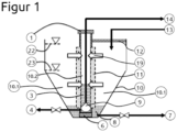
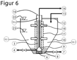
- a device for separating suspensions for thickening sludge or concentrating solids consists of the sedimentation tank 10 and the surface filter 11, 17 inserted into the sedimentation tank 10.
- the aqueous suspension containing solid particles is introduced into the sedimentation tank 10 via a feed line 13.
- Filtrate 3 is discharged from the sedimentation tank 10 via a drain line 14 via a pump 9.
- the sludge 8 settling in the sedimentation tank 10 is discharged via the drain line 7.
- the surface filter 11 consists of two cylindrical perforated plates 11.1, 11.2 which are arranged coaxially to one another.
- Filter material 11.3 is inserted between the outer perforated plate 11.1 and the inner perforated plate 11.2.
- This filter material 11.3 is preferably biological material and consists, for example, of wood chips. However, any other suitable filter material (e.g. steel or clay elements, balls) can also be used.
- the surface cylinder 11 is closed with covers 1, 6 at its opposite ends 16.
- a pump 9 is arranged inside the surface filter 11 and is surrounded by the inner perforated plate 11.2. The pump 9 works in the discharge line 14 which is led through the upper cover 6.
- the tubular surface filter 11 separates the sedimentation basin 10 into a first, outer chamber 10.1 and a second, inner chamber 10.2.
- the suspension supplied via line 13 is segmented into solids and sludge water via the surface filter 11.
- the solid particles settle in the bottom area of the first chamber 10.1. Due to the pressure difference in the first chamber 10.1 and the second chamber 10.2, the sludge water is pressed through the surface filter 11, as shown in Figure 1 indicated by the arrows 19.
- the filtrate 3 then collects in the second chamber 10.2 and is pumped away by the pump 9 via the discharge line 14.
- the sludge 8 that has settled in the first chamber 10.1 can be discharged via the line 7.
- the surface filter 11 is firmly connected to the sedimentation basin 10 via the carrier 12.
- the latter is designed in the shape of a funnel, with the opening angle ⁇ of the funnel being approximately 60°.
- the height of the sludge line is designated as 23 and the height of the water line (surface of the suspension) as 22.
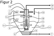
- the surface filter 11 is connected to a floating body 15, which holds it with its upper end 16 above the water line 22.
- the surface filter 11 can be compared to the Figure 1
- the design shown in the example can be made smaller and therefore has smaller pressure differences between the inner chamber 10.2 and the outer chamber 10.1. Otherwise, the design corresponds to that shown in Figure 1 shown embodiment.
- the embodiment shown is a submersible filter which is hermetically sealed at both ends with lids 1, 6 and can be immersed deep into the suspension.
- This embodiment is particularly suitable when sludge is to be thickened in deep areas of sedimentation tanks 10. At full hydrostatic pressure, the sludge water can flow directly through the surface filter 11, which leads to faster consolidation and thus to a higher solids concentration in the thickening and clearing zone. Otherwise, the structure corresponds to that in Figure 1 shown embodiment.
- Figures 4 to 9 divide the overall process into essential sub-processes.
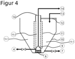
- Figure 4 shows the initial state with empty containers.
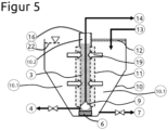
- Figure 5 shows the result of the filling sub-process.
- the sedimentation basin 10 was filled via the supply line 13. Due to the hydrostatic pressure equalization, the outer chamber 10.1 and the inner chamber 10.2 of the sedimentation basin 10 have the same filling level.
- Figure 6 shows the formation of a sludge level with a sludge surface 23 and the fluid surface 22 arranged above it.
- FIG 8 The greatest possible separation of the free sludge water by the surface filter 11 is in Figure 8 In the thickening and clearing zone there is now a thickened sewage sludge 8, which is removed via the discharge line 7. As Figure 8 As can be seen, the upper end 16 of the surface filter 11 can also be open.
- Figure 9 finally shows the emptied sedimentation tank 10 and an inner chamber 10.2 filled with fresh or process water. As indicated by the arrows 19, the water in the chamber 10.2 is pressed into the outer chamber 10.1 of the sedimentation tank 10 as a result of the pressure difference and the surface filter 11 is thereby rinsed and thus cleaned.
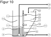
- a fourth embodiment of the device according to the invention shows Figure 10
- the surface filter 17 is formed here by a wall that is firmly integrated into the sedimentation tank 10.
- This wall also consists of an outer perforated plate 17.1 and an inner perforated plate 17.2, which are arranged parallel to one another.
- the space between the perforated plates 17.1, 17.2 is filled with filter material 17.3, which is also preferably biological material such as wood chips.
- the wall also divides the sedimentation tank 10 into two chambers 10.1, 10.2.
- the first chamber 10.1 is delimited by the outer perforated plate 17.1 and the second chamber 17.2 by the inner perforated plate 17.2.
- the filtrate 3 is pumped out of the second chamber 10.2 via the discharge line 14 by the pump 9 arranged in the second chamber 10.2.
- FIGS 11 and 12 show the surface filters 11, 17 with an integrated flushing device or ventilation device, which is formed by a pipe 20, which is preferably inserted in the axial direction A R between the two perforated plates 11.1, 11.2; 17.1, 17.2.
- This pipe 20 has holes 21 in its wall through which flushing liquid or gas can be forced, if necessary with excess pressure. The flushing can also be carried out with gas, preferably with air. Via these holes 21 Additional drainage channels are actively created, which effectively support the transport of sludge water through the surface filters 11, 17.
Landscapes
- Engineering & Computer Science (AREA)
- Mechanical Engineering (AREA)
- Life Sciences & Earth Sciences (AREA)
- Hydrology & Water Resources (AREA)
- Environmental & Geological Engineering (AREA)
- Water Supply & Treatment (AREA)
- Chemical & Material Sciences (AREA)
- Organic Chemistry (AREA)
- Filtration Of Liquid (AREA)
- Treatment Of Sludge (AREA)
Claims (11)
- Dispositif de séparation de suspensions pour l'épaississement de boues, en particulier de boues d'épuration, comprenant un bassin de sédimentation (10) dans lequel la suspension aqueuse munie de particules solides peut être amenée par une conduite d'amenée (13) et duquel des boues épaissies (8) peuvent être évacuées par une première conduite d'évacuation (7), et comprenant un filtre de surface (11, 17) susceptible d'être immergé dans la suspension et constitué d'au moins une tôle perforée extérieure (11.1, 17.1), d'une tôle perforée intérieure (11.2, 17.2) disposée à distance de celle-ci et d'un matériau filtrant (11.3, 17.3) inséré entre les deux tôles perforées (11.1, 11.2 ; 17.1, 17.2), le filtre de surface (11, 17) subdivisant le bassin de sédimentation (10) en une chambre extérieure (10.1) et en une chambre intérieure (10.2), et comprenant une pompe (9) tournée vers la tôle perforée intérieure (11.2, 17.2), qui coopère avec une deuxième conduite d'évacuation (14), ou un dispositif de décharge (4) permettant d'évacuer un filtrat (3) hors du bassin de sédimentation (10),
caractérisé en ce queau moins un tube (20) qui s'étend dans une direction axiale (AR) et dont la paroi présente des trous (21) est inséré entre la tôle perforée extérieure (11.1, 17.1) et la tôle perforée intérieure (11.2, 17.2), eten ce que la chambre intérieure (10.2) est susceptible d'être remplie d'un fluide, et le filtre de surface (11, 17) est rincé avec un fluide, en particulier avec de l'eau, pour être nettoyé, le fluide s'écoulant alors de la tôle perforée intérieure (11.2, 17.2) vers la tôle perforée extérieure (11.1, 17.1) et ressortant de celle-ci. - Dispositif selon la revendication 1,
caractérisé en ce que le filtre de surface (11) est de forme cylindrique ou polyédrique, et les tôles perforées (11.1, 11.2) sont disposées de manière concentrique l'une par rapport à l'autre. - Dispositif selon la revendication 1,
caractérisé en ce que le filtre de surface (17) est réalisé en forme de plaque, et les tôles perforées (17.1, 17.2) sont disposées parallèlement l'une à l'autre. - Dispositif selon l'une des revendications précédentes,
caractérisé en ce que le matériau filtrant (11.3, 17.3) est un substrat naturel, en particulier un matériau à base de bois. - Dispositif selon l'une des revendications précédentes,
caractérisé en ce que le filtre de surface (11, 17) dépasse par son bord supérieur (16) de la surface (22) de la suspension aqueuse (surface du fluide). - Dispositif selon l'une des revendications précédentes,
caractérisé en ce que le filtre de surface (10) est pourvu d'un corps flottant (15). - Dispositif selon l'une des revendications précédentes,
caractérisé en ce que le filtre de surface (11) est fermé à ses extrémités (16) par des couvercles (1, 6) et est complètement immergé dans la suspension aqueuse. - Procédé de séparation de suspensions pour l'épaississement de boues, en particulier de boues d'épuration, au moyen d'un dispositif comprenant un bassin de sédimentation (10) dans lequel la suspension aqueuse munie de particules solides peut être amenée par une conduite d'amenée (13) et duquel des boues épaissies (8) peuvent être évacuées par une première conduite d'évacuation (7), un filtre de surface (11, 17) étant immergé dans la suspension, qui est constitué d'au moins une tôle perforée extérieure (11.1, 17.1), d'une tôle perforée intérieure (11.2, 17.2) disposée à distance de celle-ci et d'un matériau filtrant (11.3, 17.3) inséré entre les deux tôles perforées (11.1, 11.2 ; 17.1, 17.2), le filtre de surface (11, 17) subdivisant le bassin de sédimentation (10) en une chambre extérieure (10.1) et en une chambre intérieure (10.2), et une pompe (9) étant tournée vers la tôle perforée intérieure (11.2, 17.2), qui coopère avec une deuxième conduite d'évacuation (14), ou il est prévu un dispositif de décharge (4) permettant d'évacuer un filtrat (3) hors du bassin de sédimentation (10), comprenant les étapes consistant à :a) insérer le filtre de surface (11, 17) dans le bassin de sédimentation (10),b) introduire la suspension aqueuse dans le bassin de sédimentation (10) par la conduite d'amenée (13),c) séparer les matières solides à la surface du filtre de surface (11, 17) ou de la tôle perforée extérieure (11.1, 17.1),d) collecter dans la chambre intérieure (10.2) le filtrat (3) qui sort de la tôle perforée intérieure (11.2, 17.2),e) pomper le filtrat (3), collecté dans la chambre intérieure (10.2), au moyen de la pompe (9) via la deuxième conduite d'évacuation (14), et/ou évacuer le filtrat par le dispositif de décharge (4),
caractérisé en ce quef) le fluide peut être introduit dans le filtre de surface (11, 17) par l'intermédiaire d'un tube (20), disposé dans le matériau filtrant, et de trous (21) ménagés dans la paroi du tube, etg) le filtre de surface (11, 17) est rincé avec un fluide, en particulier avec de l'eau, pour être nettoyé, le fluide s'écoulant alors de la tôle perforée intérieure (11.2, 17.2) vers la tôle perforée extérieure (11.1, 17.1) et ressortant de celle-ci. - Procédé selon la revendication 8,
caractérisé en ce que le filtre de surface (11, 17) est aéré. - Procédé selon la revendication 8 ou 9,
caractérisé en ce que le fluide de rinçage est sous une pression positive. - Procédé selon l'une des revendications 8 à 10,
caractérisé en ce que le filtre de surface (11, 17) est soulevé hors de la suspension ou du bassin de sédimentation (10) pour être nettoyé.
Applications Claiming Priority (2)
| Application Number | Priority Date | Filing Date | Title |
|---|---|---|---|
| DE102018131208.3A DE102018131208A1 (de) | 2018-12-06 | 2018-12-06 | Vorrichtung und Verfahren zum Trennen von Suspensionen |
| PCT/EP2019/082294 WO2020114808A1 (fr) | 2018-12-06 | 2019-11-22 | Système et procédé de séparation de suspensions |
Publications (2)
| Publication Number | Publication Date |
|---|---|
| EP3891105A1 EP3891105A1 (fr) | 2021-10-13 |
| EP3891105B1 true EP3891105B1 (fr) | 2024-09-04 |
Family
ID=68654510
Family Applications (1)
| Application Number | Title | Priority Date | Filing Date |
|---|---|---|---|
| EP19808799.1A Active EP3891105B1 (fr) | 2018-12-06 | 2019-11-22 | Système et procédé de séparation de suspensions |
Country Status (3)
| Country | Link |
|---|---|
| EP (1) | EP3891105B1 (fr) |
| DE (1) | DE102018131208A1 (fr) |
| WO (1) | WO2020114808A1 (fr) |
Families Citing this family (3)
| Publication number | Priority date | Publication date | Assignee | Title |
|---|---|---|---|---|
| NO347940B1 (en) * | 2022-04-06 | 2024-05-21 | Nekkar As | Device for dewatering waste in a fish cage |
| CN115180859B (zh) * | 2022-04-22 | 2023-08-25 | 浙江天造环保科技有限公司 | 一种智能化处理水洗建筑垃圾生产的淤泥生产线及方法 |
| CN116495963A (zh) * | 2023-06-05 | 2023-07-28 | 常州工学院 | 一种基于泥水辅助分离的淤泥搅拌装置 |
Citations (1)
| Publication number | Priority date | Publication date | Assignee | Title |
|---|---|---|---|---|
| JP2014000539A (ja) * | 2012-06-20 | 2014-01-09 | Swing Corp | ろ過濃縮システム及びろ過濃縮システムの運転方法 |
Family Cites Families (7)
| Publication number | Priority date | Publication date | Assignee | Title |
|---|---|---|---|---|
| EP0410961B1 (fr) * | 1986-02-14 | 1993-08-18 | STEDFELDT, Hans | Procede et appareil de separation de particules solides contenues dans un liquide |
| CA2017588C (fr) * | 1991-08-16 | 1997-03-18 | Hans Stedfeldt | Methode et dispositif ameliore de separation des particules solides contenues dans les liquides |
| FR2735379A1 (fr) * | 1995-06-13 | 1996-12-20 | Morillon Corvol Courbot | Procede d'extraction et de traitement de boues sedimentees hydrauliques et puits filtrant utilisable pour la mise en oeuvre d'un tel procede |
| SE514311C2 (sv) * | 1999-05-03 | 2001-02-05 | Hyosong Lee | Förfarande och anordning för filtrering av partiklar ur en vätska |
| DE10230671A1 (de) * | 2002-07-04 | 2004-01-22 | Markgraf, Hannelore | Verfahren und Vorrichtung zur Schlammführung aus einer Schmutzwasserbehandlungsanlage |
| AU2006222735B8 (en) * | 2005-10-06 | 2011-12-08 | Robert Hume Pannell | Multi-media clarifier or thickener |
| EP2719436A1 (fr) * | 2012-10-10 | 2014-04-16 | Biotain AB | Agencement et procédé de filtrage d'une boue rugueuse |
-
2018
- 2018-12-06 DE DE102018131208.3A patent/DE102018131208A1/de not_active Withdrawn
-
2019
- 2019-11-22 EP EP19808799.1A patent/EP3891105B1/fr active Active
- 2019-11-22 WO PCT/EP2019/082294 patent/WO2020114808A1/fr not_active Ceased
Patent Citations (1)
| Publication number | Priority date | Publication date | Assignee | Title |
|---|---|---|---|---|
| JP2014000539A (ja) * | 2012-06-20 | 2014-01-09 | Swing Corp | ろ過濃縮システム及びろ過濃縮システムの運転方法 |
Non-Patent Citations (1)
| Title |
|---|
| ANONYMOUS: "Backwashing (Water Treatment)", WIKIPEDIA, 7 December 2018 (2018-12-07), XP093008036, Retrieved from the Internet <URL:http://en.wikipedia.org/w/index.php?title=Backwashing_(water_treatment)&oldid=872408238> [retrieved on 20221214] * |
Also Published As
| Publication number | Publication date |
|---|---|
| DE102018131208A1 (de) | 2020-06-10 |
| WO2020114808A1 (fr) | 2020-06-11 |
| EP3891105A1 (fr) | 2021-10-13 |
Similar Documents
| Publication | Publication Date | Title |
|---|---|---|
| DE68911553T2 (de) | Verfahren und Vorrichtung zur Behandlung von Wasser durch Absetzen unter Verwendung von feinem Sand. | |
| DE19648519C2 (de) | Verfahren und Anlage zur Stofftrennung mittels Membranfiltration | |
| DE69617310T2 (de) | Vorrichtung und Verfahren zur Reinigung von Abwasser | |
| DE3207279A1 (de) | Verfahren und vorrichtung zum reinigen von becken | |
| EP2709840A1 (fr) | Presse à vis | |
| DE69735165T2 (de) | Dreizonenvorrichtung zur reinigung durch flotation mit gelöster luft mit verbessertem wirkungsgrad | |
| EP3891105B1 (fr) | Système et procédé de séparation de suspensions | |
| EP2376392B1 (fr) | Réacteur à flux ascendant à recirculation de biomasse commandée | |
| EP2114832B1 (fr) | Procédé et dispositif de purification d'eau contenant des impuretés sous forme d'ions sulfate et d'ions de métal lourd | |
| DE833928C (de) | Verfahren zur Abwasserreinigung mit Gewinnung von Faulschlamm | |
| DE19719798C1 (de) | Verfahren zum Entfernen von Biomasse aus einer Flüssigkeit mit Hilfe eines Flotationsreaktors | |
| DE29620426U1 (de) | Anlage zur Stofftrennung mittels Membranfiltration | |
| EP2225012A1 (fr) | Installation de traitement d'eaux usées et procédé de traitement d'eaux usées | |
| DD146938A5 (de) | Verfahren und anlage zur wasseraufbereitung,abwasserreinigung und reinigung des verunreinigten wassers | |
| DE3138246A1 (de) | Verfahren und vorrichtung zur behandlung von abwasser | |
| CH626864A5 (en) | Process and arrangement for treating liquids, in particular waste water. | |
| EP1138363B1 (fr) | Dispositif de soutirage d'eau purifiée d'un récipient lors de la purification biologique d'eaux usées | |
| DE10059839C2 (de) | Verfahren und Vorrichtung zur Schlammeindickung in mechanisch-biologischen Abwasser-Kläranlagen | |
| EP1132348B1 (fr) | Installation et procédé d'épuration d'eaux usées | |
| DE10220106B4 (de) | Verfahren zur Schlammeindickung in mechanisch-biologischen Abwasser-Kläranlagen | |
| DE102017119555B3 (de) | Emulsionsspaltanlage | |
| DE29810474U1 (de) | Vorrichtung zum Eindicken von Schlämmen | |
| EP1852399A2 (fr) | station d'épuration d'eau compacte, procédé de traitement des eaux usées | |
| EP0999186A2 (fr) | Procédé pour la purification et le traitement de résidus liquides résultant du nettoyage de véhicules citerne et silo routiers, de wagons citerne ferroviaires et de bateaux citerne | |
| CH688737A5 (de) | Anlage zur verwertung organischer abfaelle |
Legal Events
| Date | Code | Title | Description |
|---|---|---|---|
| STAA | Information on the status of an ep patent application or granted ep patent |
Free format text: STATUS: UNKNOWN |
|
| STAA | Information on the status of an ep patent application or granted ep patent |
Free format text: STATUS: THE INTERNATIONAL PUBLICATION HAS BEEN MADE |
|
| PUAI | Public reference made under article 153(3) epc to a published international application that has entered the european phase |
Free format text: ORIGINAL CODE: 0009012 |
|
| STAA | Information on the status of an ep patent application or granted ep patent |
Free format text: STATUS: REQUEST FOR EXAMINATION WAS MADE |
|
| 17P | Request for examination filed |
Effective date: 20210702 |
|
| AK | Designated contracting states |
Kind code of ref document: A1 Designated state(s): AL AT BE BG CH CY CZ DE DK EE ES FI FR GB GR HR HU IE IS IT LI LT LU LV MC MK MT NL NO PL PT RO RS SE SI SK SM TR |
|
| DAV | Request for validation of the european patent (deleted) | ||
| DAX | Request for extension of the european patent (deleted) | ||
| STAA | Information on the status of an ep patent application or granted ep patent |
Free format text: STATUS: EXAMINATION IS IN PROGRESS |
|
| 17Q | First examination report despatched |
Effective date: 20221221 |
|
| GRAP | Despatch of communication of intention to grant a patent |
Free format text: ORIGINAL CODE: EPIDOSNIGR1 |
|
| STAA | Information on the status of an ep patent application or granted ep patent |
Free format text: STATUS: GRANT OF PATENT IS INTENDED |
|
| INTG | Intention to grant announced |
Effective date: 20231027 |
|
| GRAJ | Information related to disapproval of communication of intention to grant by the applicant or resumption of examination proceedings by the epo deleted |
Free format text: ORIGINAL CODE: EPIDOSDIGR1 |
|
| STAA | Information on the status of an ep patent application or granted ep patent |
Free format text: STATUS: EXAMINATION IS IN PROGRESS |
|
| GRAP | Despatch of communication of intention to grant a patent |
Free format text: ORIGINAL CODE: EPIDOSNIGR1 |
|
| STAA | Information on the status of an ep patent application or granted ep patent |
Free format text: STATUS: GRANT OF PATENT IS INTENDED |
|
| INTC | Intention to grant announced (deleted) | ||
| INTG | Intention to grant announced |
Effective date: 20240404 |
|
| GRAS | Grant fee paid |
Free format text: ORIGINAL CODE: EPIDOSNIGR3 |
|
| GRAA | (expected) grant |
Free format text: ORIGINAL CODE: 0009210 |
|
| STAA | Information on the status of an ep patent application or granted ep patent |
Free format text: STATUS: THE PATENT HAS BEEN GRANTED |
|
| AK | Designated contracting states |
Kind code of ref document: B1 Designated state(s): AL AT BE BG CH CY CZ DE DK EE ES FI FR GB GR HR HU IE IS IT LI LT LU LV MC MK MT NL NO PL PT RO RS SE SI SK SM TR |
|
| REG | Reference to a national code |
Ref country code: GB Ref legal event code: FG4D Free format text: NOT ENGLISH |
|
| REG | Reference to a national code |
Ref country code: CH Ref legal event code: EP |
|
| REG | Reference to a national code |
Ref country code: IE Ref legal event code: FG4D Free format text: LANGUAGE OF EP DOCUMENT: GERMAN |
|
| REG | Reference to a national code |
Ref country code: DE Ref legal event code: R096 Ref document number: 502019012071 Country of ref document: DE |
|
| REG | Reference to a national code |
Ref country code: LT Ref legal event code: MG9D |
|
| REG | Reference to a national code |
Ref country code: NL Ref legal event code: MP Effective date: 20240904 |
|
| PG25 | Lapsed in a contracting state [announced via postgrant information from national office to epo] |
Ref country code: NO Free format text: LAPSE BECAUSE OF FAILURE TO SUBMIT A TRANSLATION OF THE DESCRIPTION OR TO PAY THE FEE WITHIN THE PRESCRIBED TIME-LIMIT Effective date: 20241204 |
|
| PG25 | Lapsed in a contracting state [announced via postgrant information from national office to epo] |
Ref country code: FI Free format text: LAPSE BECAUSE OF FAILURE TO SUBMIT A TRANSLATION OF THE DESCRIPTION OR TO PAY THE FEE WITHIN THE PRESCRIBED TIME-LIMIT Effective date: 20240904 Ref country code: GR Free format text: LAPSE BECAUSE OF FAILURE TO SUBMIT A TRANSLATION OF THE DESCRIPTION OR TO PAY THE FEE WITHIN THE PRESCRIBED TIME-LIMIT Effective date: 20241205 Ref country code: PL Free format text: LAPSE BECAUSE OF FAILURE TO SUBMIT A TRANSLATION OF THE DESCRIPTION OR TO PAY THE FEE WITHIN THE PRESCRIBED TIME-LIMIT Effective date: 20240904 |
|
| PG25 | Lapsed in a contracting state [announced via postgrant information from national office to epo] |
Ref country code: BG Free format text: LAPSE BECAUSE OF FAILURE TO SUBMIT A TRANSLATION OF THE DESCRIPTION OR TO PAY THE FEE WITHIN THE PRESCRIBED TIME-LIMIT Effective date: 20240904 |
|
| PG25 | Lapsed in a contracting state [announced via postgrant information from national office to epo] |
Ref country code: LV Free format text: LAPSE BECAUSE OF FAILURE TO SUBMIT A TRANSLATION OF THE DESCRIPTION OR TO PAY THE FEE WITHIN THE PRESCRIBED TIME-LIMIT Effective date: 20240904 |
|
| PG25 | Lapsed in a contracting state [announced via postgrant information from national office to epo] |
Ref country code: HR Free format text: LAPSE BECAUSE OF FAILURE TO SUBMIT A TRANSLATION OF THE DESCRIPTION OR TO PAY THE FEE WITHIN THE PRESCRIBED TIME-LIMIT Effective date: 20240904 |
|
| PG25 | Lapsed in a contracting state [announced via postgrant information from national office to epo] |
Ref country code: ES Free format text: LAPSE BECAUSE OF FAILURE TO SUBMIT A TRANSLATION OF THE DESCRIPTION OR TO PAY THE FEE WITHIN THE PRESCRIBED TIME-LIMIT Effective date: 20240904 Ref country code: RS Free format text: LAPSE BECAUSE OF FAILURE TO SUBMIT A TRANSLATION OF THE DESCRIPTION OR TO PAY THE FEE WITHIN THE PRESCRIBED TIME-LIMIT Effective date: 20241204 |
|
| PG25 | Lapsed in a contracting state [announced via postgrant information from national office to epo] |
Ref country code: RS Free format text: LAPSE BECAUSE OF FAILURE TO SUBMIT A TRANSLATION OF THE DESCRIPTION OR TO PAY THE FEE WITHIN THE PRESCRIBED TIME-LIMIT Effective date: 20241204 Ref country code: PL Free format text: LAPSE BECAUSE OF FAILURE TO SUBMIT A TRANSLATION OF THE DESCRIPTION OR TO PAY THE FEE WITHIN THE PRESCRIBED TIME-LIMIT Effective date: 20240904 Ref country code: NO Free format text: LAPSE BECAUSE OF FAILURE TO SUBMIT A TRANSLATION OF THE DESCRIPTION OR TO PAY THE FEE WITHIN THE PRESCRIBED TIME-LIMIT Effective date: 20241204 Ref country code: LV Free format text: LAPSE BECAUSE OF FAILURE TO SUBMIT A TRANSLATION OF THE DESCRIPTION OR TO PAY THE FEE WITHIN THE PRESCRIBED TIME-LIMIT Effective date: 20240904 Ref country code: HR Free format text: LAPSE BECAUSE OF FAILURE TO SUBMIT A TRANSLATION OF THE DESCRIPTION OR TO PAY THE FEE WITHIN THE PRESCRIBED TIME-LIMIT Effective date: 20240904 Ref country code: GR Free format text: LAPSE BECAUSE OF FAILURE TO SUBMIT A TRANSLATION OF THE DESCRIPTION OR TO PAY THE FEE WITHIN THE PRESCRIBED TIME-LIMIT Effective date: 20241205 Ref country code: FI Free format text: LAPSE BECAUSE OF FAILURE TO SUBMIT A TRANSLATION OF THE DESCRIPTION OR TO PAY THE FEE WITHIN THE PRESCRIBED TIME-LIMIT Effective date: 20240904 Ref country code: ES Free format text: LAPSE BECAUSE OF FAILURE TO SUBMIT A TRANSLATION OF THE DESCRIPTION OR TO PAY THE FEE WITHIN THE PRESCRIBED TIME-LIMIT Effective date: 20240904 Ref country code: BG Free format text: LAPSE BECAUSE OF FAILURE TO SUBMIT A TRANSLATION OF THE DESCRIPTION OR TO PAY THE FEE WITHIN THE PRESCRIBED TIME-LIMIT Effective date: 20240904 |
|
| PG25 | Lapsed in a contracting state [announced via postgrant information from national office to epo] |
Ref country code: NL Free format text: LAPSE BECAUSE OF FAILURE TO SUBMIT A TRANSLATION OF THE DESCRIPTION OR TO PAY THE FEE WITHIN THE PRESCRIBED TIME-LIMIT Effective date: 20240904 |
|
| REG | Reference to a national code |
Ref country code: DE Ref legal event code: R082 Ref document number: 502019012071 Country of ref document: DE Representative=s name: GRAMM, LINS & PARTNER PATENT- UND RECHTSANWAEL, DE Ref country code: DE Ref legal event code: R081 Ref document number: 502019012071 Country of ref document: DE Owner name: KOLLER MASCHINEN- UND ANLAGENBAU GMBH, DE Free format text: FORMER OWNER: MUTEC-MARKGRAF GMBH, 38459 BAHRDORF, DE |
|
| RAP2 | Party data changed (patent owner data changed or rights of a patent transferred) |
Owner name: KOLLER MASCHINEN- UND ANLAGENBAU GMBH |
|
| PG25 | Lapsed in a contracting state [announced via postgrant information from national office to epo] |
Ref country code: IS Free format text: LAPSE BECAUSE OF FAILURE TO SUBMIT A TRANSLATION OF THE DESCRIPTION OR TO PAY THE FEE WITHIN THE PRESCRIBED TIME-LIMIT Effective date: 20250104 Ref country code: PT Free format text: LAPSE BECAUSE OF FAILURE TO SUBMIT A TRANSLATION OF THE DESCRIPTION OR TO PAY THE FEE WITHIN THE PRESCRIBED TIME-LIMIT Effective date: 20250106 |
|
| PG25 | Lapsed in a contracting state [announced via postgrant information from national office to epo] |
Ref country code: SM Free format text: LAPSE BECAUSE OF FAILURE TO SUBMIT A TRANSLATION OF THE DESCRIPTION OR TO PAY THE FEE WITHIN THE PRESCRIBED TIME-LIMIT Effective date: 20240904 Ref country code: RO Free format text: LAPSE BECAUSE OF FAILURE TO SUBMIT A TRANSLATION OF THE DESCRIPTION OR TO PAY THE FEE WITHIN THE PRESCRIBED TIME-LIMIT Effective date: 20240904 |
|
| PG25 | Lapsed in a contracting state [announced via postgrant information from national office to epo] |
Ref country code: EE Free format text: LAPSE BECAUSE OF FAILURE TO SUBMIT A TRANSLATION OF THE DESCRIPTION OR TO PAY THE FEE WITHIN THE PRESCRIBED TIME-LIMIT Effective date: 20240904 |
|
| PG25 | Lapsed in a contracting state [announced via postgrant information from national office to epo] |
Ref country code: CZ Free format text: LAPSE BECAUSE OF FAILURE TO SUBMIT A TRANSLATION OF THE DESCRIPTION OR TO PAY THE FEE WITHIN THE PRESCRIBED TIME-LIMIT Effective date: 20240904 |
|
| PG25 | Lapsed in a contracting state [announced via postgrant information from national office to epo] |
Ref country code: IT Free format text: LAPSE BECAUSE OF FAILURE TO SUBMIT A TRANSLATION OF THE DESCRIPTION OR TO PAY THE FEE WITHIN THE PRESCRIBED TIME-LIMIT Effective date: 20240904 Ref country code: SK Free format text: LAPSE BECAUSE OF FAILURE TO SUBMIT A TRANSLATION OF THE DESCRIPTION OR TO PAY THE FEE WITHIN THE PRESCRIBED TIME-LIMIT Effective date: 20240904 |
|
| REG | Reference to a national code |
Ref country code: DE Ref legal event code: R097 Ref document number: 502019012071 Country of ref document: DE |
|
| REG | Reference to a national code |
Ref country code: CH Ref legal event code: PL |
|
| PG25 | Lapsed in a contracting state [announced via postgrant information from national office to epo] |
Ref country code: MC Free format text: LAPSE BECAUSE OF FAILURE TO SUBMIT A TRANSLATION OF THE DESCRIPTION OR TO PAY THE FEE WITHIN THE PRESCRIBED TIME-LIMIT Effective date: 20240904 |
|
| PG25 | Lapsed in a contracting state [announced via postgrant information from national office to epo] |
Ref country code: DK Free format text: LAPSE BECAUSE OF FAILURE TO SUBMIT A TRANSLATION OF THE DESCRIPTION OR TO PAY THE FEE WITHIN THE PRESCRIBED TIME-LIMIT Effective date: 20240904 |
|
| PLBE | No opposition filed within time limit |
Free format text: ORIGINAL CODE: 0009261 |
|
| STAA | Information on the status of an ep patent application or granted ep patent |
Free format text: STATUS: NO OPPOSITION FILED WITHIN TIME LIMIT |
|
| PG25 | Lapsed in a contracting state [announced via postgrant information from national office to epo] |
Ref country code: LU Free format text: LAPSE BECAUSE OF NON-PAYMENT OF DUE FEES Effective date: 20241122 |
|
| REG | Reference to a national code |
Ref country code: CH Ref legal event code: PL |
|
| PG25 | Lapsed in a contracting state [announced via postgrant information from national office to epo] |
Ref country code: CH Free format text: LAPSE BECAUSE OF NON-PAYMENT OF DUE FEES Effective date: 20241130 |
|
| 26N | No opposition filed |
Effective date: 20250605 |
|
| GBPC | Gb: european patent ceased through non-payment of renewal fee |
Effective date: 20241204 |
|
| REG | Reference to a national code |
Ref country code: BE Ref legal event code: MM Effective date: 20241130 |
|
| PG25 | Lapsed in a contracting state [announced via postgrant information from national office to epo] |
Ref country code: SE Free format text: LAPSE BECAUSE OF FAILURE TO SUBMIT A TRANSLATION OF THE DESCRIPTION OR TO PAY THE FEE WITHIN THE PRESCRIBED TIME-LIMIT Effective date: 20240904 |
|
| PG25 | Lapsed in a contracting state [announced via postgrant information from national office to epo] |
Ref country code: BE Free format text: LAPSE BECAUSE OF NON-PAYMENT OF DUE FEES Effective date: 20241130 Ref country code: GB Free format text: LAPSE BECAUSE OF NON-PAYMENT OF DUE FEES Effective date: 20241204 |
|
| PG25 | Lapsed in a contracting state [announced via postgrant information from national office to epo] |
Ref country code: FR Free format text: LAPSE BECAUSE OF NON-PAYMENT OF DUE FEES Effective date: 20241130 |
|
| PG25 | Lapsed in a contracting state [announced via postgrant information from national office to epo] |
Ref country code: IE Free format text: LAPSE BECAUSE OF NON-PAYMENT OF DUE FEES Effective date: 20241122 |
|
| PGFP | Annual fee paid to national office [announced via postgrant information from national office to epo] |
Ref country code: DE Payment date: 20251120 Year of fee payment: 7 |
|
| PG25 | Lapsed in a contracting state [announced via postgrant information from national office to epo] |
Ref country code: AT Free format text: LAPSE BECAUSE OF NON-PAYMENT OF DUE FEES Effective date: 20241122 |
|
| REG | Reference to a national code |
Ref country code: AT Ref legal event code: MM01 Ref document number: 1720246 Country of ref document: AT Kind code of ref document: T Effective date: 20241122 |
|
| PG25 | Lapsed in a contracting state [announced via postgrant information from national office to epo] |
Ref country code: HU Free format text: LAPSE BECAUSE OF FAILURE TO SUBMIT A TRANSLATION OF THE DESCRIPTION OR TO PAY THE FEE WITHIN THE PRESCRIBED TIME-LIMIT; INVALID AB INITIO Effective date: 20191122 |
|
| PG25 | Lapsed in a contracting state [announced via postgrant information from national office to epo] |
Ref country code: CY Free format text: LAPSE BECAUSE OF FAILURE TO SUBMIT A TRANSLATION OF THE DESCRIPTION OR TO PAY THE FEE WITHIN THE PRESCRIBED TIME-LIMIT; INVALID AB INITIO Effective date: 20191122 |